

IWAKI PUMPS MDG-M4 series, MDG-M4T6B115L, MDG-M4T6B220H, MDG-M4S6B220, MDG-M4S6B115L Instruction Manual
...
IWAKI Magnet Gear Pump
MDG-M4 (built-in type)
Instruction Manual
Read this manual before use of product

This instruction manual includes descriptions of the correct
handling of the pump, maintenance and inspection procedures
and troubleshooting. You are requested to read the manual
carefully so that the pump can safely be used to the full extent
of its capacity for a long period of time.
Contents
Item
■
Safety Instruction ............................................ 3
■
Page
① Inspection after Unpacking ............................. 4
② Principle of operation ...................................... 4
③ Pump Identification Codes .............................. 5
④ Names of Parts and Structure .......................... 6
⑤ Precautionary measures .................................. 7
⑥ Installation, Piping and Wiring ....................... 9
⑦ Operation .........................................................11
⑧ Maintenance and Inspection ............................13
⑨ Disassembling and Reassembling ...................14
⑩ Causes of Trouble and Troubleshooting ..........16
⑪ Performance and Sizes ....................................17
⑫ Repair Service .................................................19
Export Restrictions
Technical information contained in this instruction manual might be treated as controlled
technology in your countries, due to agreements in international regime for export control.
Please be reminded that export license/permission could be required when this manual is
provided, due to export control regulations of your country.
— 2 —
Safety Instruction
CautionElectrical Shock
CautionElectrical Shock
CautionElectrical Shock
Prohibited
CautionElectrical Shock
GroundingWear protective
Prohibited
CautionElectrical Shock
Prohibited
CautionElectrical Shock
Prohibited
CautionElectrical Shock
Prohibited
CautionElectrical Shock
Prohibited
CautionElectrical Shock
Prohibited
CautionElectrical Shock
Prohibited
CautionElectrical Shock
CautionElectrical Shock
CautionElectrical Shock
CautionElectrical Shock
CautionElectrical Shock
No Remodeling
Prohibited
GroundingWear protective
CautionElectrical Shock
GroundingWear protective
gear
CautionElectrical Shock
CautionElectrical Shock
CautionElectrical Shock
Warning
Turn off the power supply.
●
Working without disconnecting the power supply may
cause an electrical shock. Before engaging upon any
working procedures involving the pump, make sure to turn
the power supply switch off and to stop the pump and
other related devices.
Terminate operation!
●
When you detect or become aware of a dangerous sign or
abnormal condition during operation, terminate the
operation immediately and start it from the beginning
again.
For specified application only.
●
The use of a pump in an application other than those
clearly specified may result in injury or damage to the
pump. Use the pump strictly in accordance with the pump
specifications and application range.
No remodeling!
●
Never remodel a pump. Otherwise, a serious accident
may result. Iwaki will not be responsible for any accident
or damage of any kind which is caused by the user
remodeling the pump without first obtaining permission or
instructions from Iwaki.
Wear protectors.
●
If you touch or come in contact with any type of
hazardous chemical liquid, including but not limited to
chemicals, you may experience a serious injury. Wear
protective gear (protective mask, gloves, etc.) during the
pump operation.
Caution
Qualified operators only!
●
The pump operator and pump operation supervisor must
not allow any operators who have little or no knowledge
of the pump to run or operate the pump. Pump operators
must have a sound knowledge of the pump and its
operation.
Specified power only.
●
Do not operate the pump on voltage which is not specified
on the nameplate. Failure to do so may result in damage
or fire. Only the specified power level is to be applied.
Do not wet or dampen!
●
If the motor or wiring cable becomes wet or dampened
with the operating liquid by mistake, this may result in a
fire or cause an electrical shock. Install the motor and
wiring cable in positions which are not likely to become
wet or dampened with any liquid.
Ventilate!
●
Poisoning may result during an operation which involves
toxic or odorous liquid. Ventilate the operating site
sufficiently.
Spill-out accident!
●
Protective measures should be taken against any
accidental spill-out or leakage of the operating liquid as a
result of unexpected damage on the pump or the related
piping.
Caution
Damaged pump
●
Never operate a damaged pump. A damaged pump may
cause leakage or electrical shock.
Operating site must be free of water and
●
humidity
The pump is not designed to be water-proof or dust-proof.
The use of the pump in places where water splashes or
humidity is high may result in an electrical shock or short
circuit.
Do not damage or change power cable!
●
Do not scratch, damage, process, or pull the power cable
forcibly. An extra load onto the cable, such as heating the
cable or placing something heavy on the cable, may
damage the cable and finally cause a fire or an electrical
shock.
Do not cover the motor!
●
Running a covered motor may accumulate heat inside the
motor and cause a fire or a mechanical failure. Ventilate
the motor sufficiently.
Arrange grounding!
●
Do not operate the pump without connecting the
grounding wire. Otherwise, an electrical shock may
result. Make sure the grounding wire is connected with
the grounding terminal.
Caution
Install an earth leakage breaker (option)!
●
The operation of a pump without using an earth leakage
breaker may cause an electrical shock. Please purchase an
optional leakage breaker and install in the system.
Power cable cannot be replaced.
●
Never use a damaged or affected power cable. Otherwise,
a fire or an electrical shock may result. Handle the power
cable carefully, as it cannot to be replaced with a new
cable. (The pump unit itself must be replaced in that
circumstance.)
Limited operating site and storage
●
Do not install or store the pump in the following places:
*Places where a flammable gas or material is used or
stored.
*Places where the ambient temperature is extremely high
(40˚C or higher) or extremely low (0˚C or lower).
Do not drain the liquid in the site.
●
The liquid discharged out of the pump, including a
hazardous chemical liquid, must be drained into a special
container. Never drain such liquid directly onto the floor
in or near the operation site.
Disposal of used pump
●
Disposal of used or damaged pumps must be done in
accordance with the relevant local laws and regulations.
(Consult a licensed industrial waste products disposing
company.)
Explosion Protection
This s y mb ol ide nt i fies in format ion a bou t avoidi n g ex plosion s i n p ot e nt ia l ly
explosive atmo sp he re s i n a c co rd a n ce w it h E C Di r e ct ive 9 4/9/ EC (ATEX ).
— 3 —
InspectionafterUnpacking
①
Upon unpacking, check the following points to confirm that the product is what you
have ordered. If you find anything wrong, please contact the dealer you placed your
order with.
1
Do the model of pump, discharge, discharge pressure, voltage, and other items
shown on the nameplate correspond with those of the pump ordered by you?
2
Is the product not damaged or are the nuts and bolts not loosened during delivery?
Please examine by sight or touch.
PrincipleofOperation
②
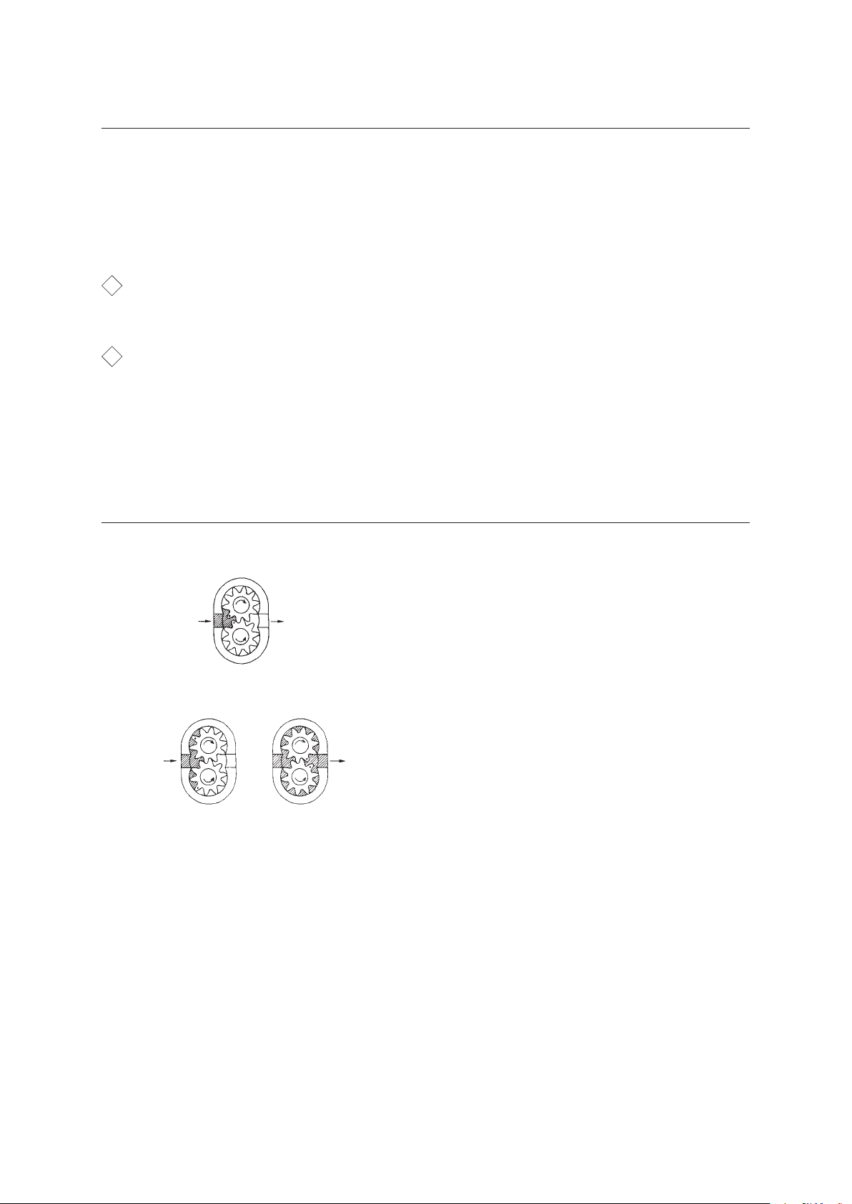
IN OUT
Fig.A
IN OUT
Fig.B Fig.C
The Iwaki Magnet Gear Pump comprises a
pair of gears driven by a magnet coupling
and casing in which the gears are fitted
exactly. (Fig. A)
Liquid introduced from the IN side feeds
into the grooves between the teeth of the
gears and is transferred to the OUT side by
rotation of the gears. (Fig. B)
This liquid is forced out of the grooves
between the gear teeth by meshing of the
gears. (Fig. C)
— 4 —

PumpIdentificationCodes
③
MDG - M4 S 6 B 115 H
① ② ③ ④ ⑤
① Represents the temperature range and viscosity limit of the liquid to be
handled.
S : Tem p er a tur e ............ b e tw e en 0 an d 5 0ºC
Vis co s ity .................. b e l ow 3 0mP a·s
T : Tem p er a tur e ............ b e tw e en 0 an d 9 5 ºC
Vis co s ity .................. b e l ow 8 0mP a·s(100 W mo tor)
below 200mPa·s(150W mo tor)
② Represents the m ax imu m discha rge pressu re.
6 : 0.6MPa
③ Connection
B : 1/4NPT
④ Li ne volta ge
115 : AC115V single phase
220 : AC220 ~ 240V single phase
⑤ Non-standard specif ication code
Without code : Equipped with a 100W motor
H : Equipped with a 150W motor
— 5 —
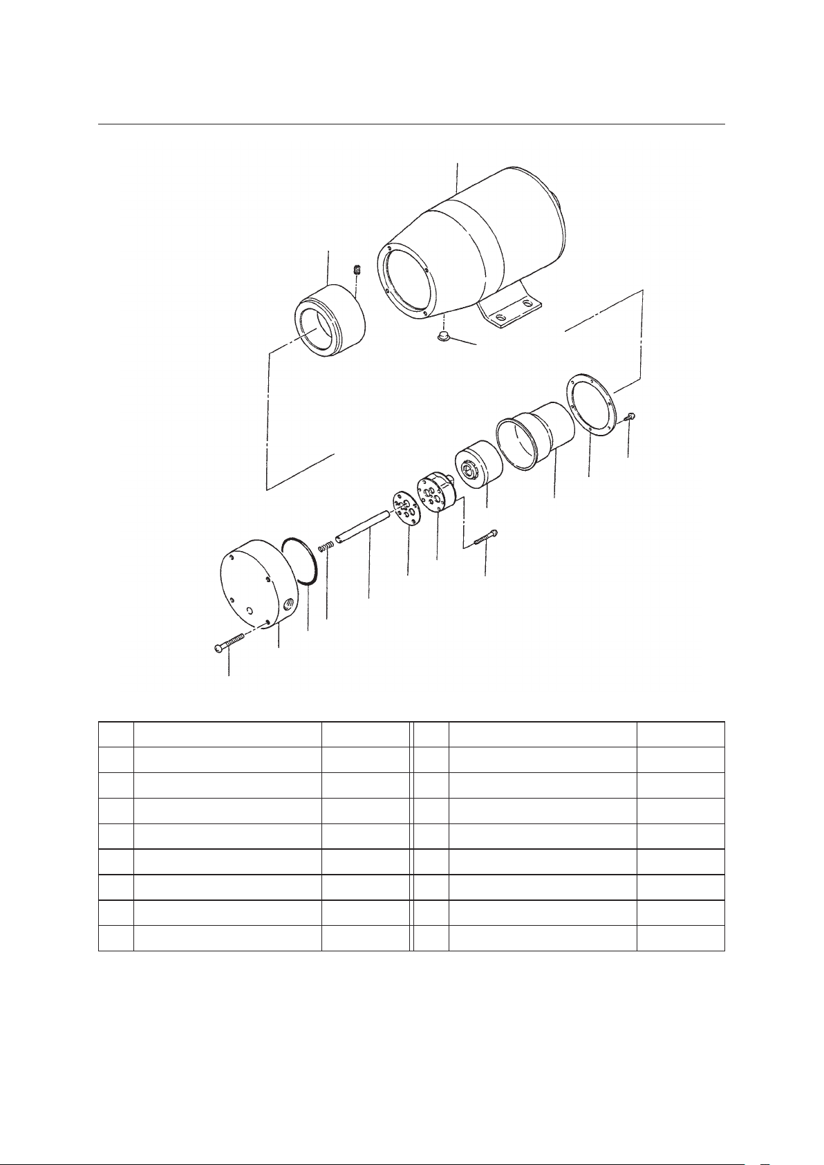
NamesofPartsandStructure
④
1
4
25
28
7
6
5
47
10
9
20
11
19
29
No. Name Number No. Name Number
1 Motor 1 19 Pump body 1
4 Driving magnet assy 1 set 20 Shaft spring 1
5 Rear casing 1 25 Cap 1
6 Magnet capsule 1 28 Screw M3×10 6
7 Mounting plate 1 29 Screw M4×35 4
9 Driving gear shaft 1 30 Screw M3×25 4
10 Gasket 1 47 Gear case unit 1 set
11 O ring 1
30
— 6 —
 Loading...