

IWAKI PUMPS MDF-L250, MDF-L401lMDF-L422, MDF-L series, MDF-L505, MDF-L507 Instruction Manual
...Page 1
Read this manual before use of product
IWAKI Magnetic Drive Pump
Model MDF-L
Instruction Manual
Page 2

Thank you for selecting the IWAKI Magnetic Drive Pump type MDF-L. This instruction
manual has been prepared to ensure correct and safe handling of the pump. Please read this
manual carefully and thoroughly prior to operating the pump.
Pay special attention to the "Safety Instruction to Prevent Personal Injuries," "Warning," and
"Caution" messages included in this manual.
This instruction manual should be kept by each end user and within reach of the actual
operator, for quick reference when needed.
Contents
IMPORTANT INSTRUCTIONS ················································ 1~~5
Safety Instructions to Prevent Personal Injuries
OUTLINE OF PRODUCT······················································ 6~~14
1. Before Using Pump ·································· 7
2. Operating Principle ··································· 7
3. Identification Codes ·································· 8
4. Specifications
and Outer Dimensions ····························· 9
5. Names of Parts ······································ 11
PUMP OPERATION ···························································· 15~~30
1. Handling Instructions ····························· 16
2. Installation ·············································· 21
3. Piping ····················································· 22
4. Wiring ····················································· 26
5. Operation Step ······································· 27
MAINTENANCE ··································································· 31~~43
1. Causes of Trouble
and Troubleshooting ································32
2. Maintenance and Inspection ·················· 35
3. Spare Parts ············································ 39
4. Disassembly and Assembly ··················· 40
Please contact the IWAKI sales office or IWAKI dealer for any
inquiries or questions regarding this product.
Page 3

- 1 -
IMPORTANT INSTRUCTIONS
Important notes and statements for safe operation, preventing physical injury, and property damage,
are included on the body of the product and in the attached instruction manual.
Always Observe These Safety Instructions!
Safety Instruction to Prevent Personal Injuries
Warning
Ignoring this message can lead to improper
handling resulting in death or serious injury to the
operator.
Caution
Ignoring this message can lead to improper
handling resulting in injury to the operator or
damage to the product.
Page 4
- 2 -
Caution
Wear
protective gear
Caution
Prohibited
Power off
Caution
Prohibited
Caution
Prohibited
Wear
protective gear
Safety Section
WARNING
• Damaged or deteriorated tools are very dangerous. Use qualified and suitable
tools only.
• Use of protectors: When disassembling, assembling, and conducting maintenance
or when handling a dangerous type of liquid or a liquid of unknown property, be sure
to wear safety gloves, a helmet, and protective shoes. In addition, when handling
wet-end parts, always wear protective goggles, masks, etc.
• To prevent death or injury from a falling pump, make sure the rope or chain used
for lifting the pump is not accidentally cut or disconnected during installation. Make
sure the rope or the chain used to lift the pump has sufficient strength in relation to
the pump load. Also, be sure not to stand underneath a lifted or suspended pump.
• When fixing the pump with rope or chain, be sure to use special bolts (or rings) for
lifting. Never use any other points for lifting the pump.
• Always turn off the power supply prior to servicing the pump. Make special pro-
visions so that no other operator mistakenly turns on the power supply while someone is working on the pump. In a noisy or poor visibity environment, display a sign
near the power supply switch to notify others that someone is "WORKING" on the
pump. Power supply mistakenly turned on during maintenance may lead to personal
injury. Each operator must be especially careful of power supply operation.
• To ensure greater safety, check and make sure that there is no one near the
pump when switching on the power supply. The pump is not equipped with an
ON/OFF switch. Connecting the power cable supplies the power to the pump and
starts the operation.
• Run the pump at the specified power supply voltage on the nameplate only.
Otherwise, fire or electric shock may result.
• If the pump operation is stopped due to a power failure or closure of discharge
wire, turn off the power switch at once. After normal conditions return, turn the
switch on again.
• Do not use the pump for anything that it is not designed to do. User’s failure to
observe this instruction exempts IWAKI from any responsibility for personal injury or
damage to the equipment or facility caused by the pump’s misuse.
• When handling a toxic or odorant liquid, ventilate the working area well. In addi-
tion, the operator must wear protector gear (such as a safety mask, safety goggles,
and protective gloves).
Page 5
WARNING
• Do not allow toxic substances such as lubricants, solvents, or similar substances to flow into the local sewage system or river systems. Do not drain haz-
ardous liquids such as chemical solutions discharged out of the pump directly onto
the ground. Instead, drain such liquids into some kind of container. Observe the
laws and regulations related to the application, handling, and processing of hazardous substances.
• Do not pass under a raised pump.
Never pass under a raised pump. A serious injury could occur if the pump is accidentally dropped.
• No remodeling!
Remodeling of the pump by the user may result in serious personal injury, electric
shock, or damage to the pump. Do not attempt remodeling as it is very dangerous.
• Cautions when dangerous liquids are transferred.
When the pumps are used to transfer the dangerous liquids mentioned as below, the
pumps always must be checked and watched so that the liquids can not be leaked.
The operation of the pumps leaking the liquids may result in personal injury and/or
explosion, fire accidents.
• Explosive, fire-spreading and inflammable liquids
• Corrosive and stimulus toxic liquids
• Liquids detrimental to health
CAUTION
• Qualified operators only!
The pump operator and pump operation supervisor must not allow any operators who
have little or no knowledge of the pump to run operate the pump. Pump operators
must have a sound knowledge of the pump and its operation.
• For specified application only
The pump is designed and manufactured to the specifications agreed upon by the
user and IWAKI. The use of a pump in any application other than those clearly specified may result in injury or damage to the pump. Use the pump strictly in accordance
with the pump specifications and application range. If you change any specification,
contact IWAKI or your dealer.
• Ventilate!
Poisoning may result during an operation which involves toxic or odorous liquid.
Ventilate the operating site sufficiently.
- 3 -
Prohibited
No Remodeling
Safety Section
Prohibited
Caution
Page 6

CAUTION
• Spill-out prevention measures
Appropriate protective measures should be taken against any spill-out accidents
involving the operating liquid as a result of unexpected damage to the pump or the
piping. Never discharge hazardous liquid, including, but not limited to, chemical liquid, over the ground or floor on the pump operating site. Follow local rules and regulations in disposing of hazardous substances.
• Do not operate the pump dry.
Do not run the pump dry (without liquid inside the pump). Heat generated as a result
of abrasion between elements inside the pump during operation without liquid may
damage the inside of the pump. Operating the pump with the suction valve fully
closed will result in dry operation.
• Keep away from heat or flame.
Do not place any open flame or flammable object near the pump.
• Do not stand on the pump.
Do not stand on the pump or use the pump as a step under any circumstances.
Otherwise, you may experience a serious injury.
• Do not touch the pump.
When the pump is used to feed a hot liquid, do not touch the pump or the piping with
your bare hands during and immediately after operation as their surfaces are dangerously hot.
• Arrange grounding!
Do not operate the pump without connecting the grounding wire. Otherwise, an electrical shock may result. Make sure the grounding wire is connected with the grounding terminal.
• Install an earth leakage breaker
The operation of a pump without using an earth leakage breaker may cause an electrical shock. Please install an optional leakage breaker in the system.
• Do not install or store the pump in the following places.
• Places where flammable gas, dust or material is used or placed.
• Places where corrosive gas (chlorine gas or the like) is generated.
• Places where the ambient temperature is extremely high (40 °C or higher) or
extremely low, 0 °C or lower.
• Places where the pump is exposed to extreme dust or humidity. (Excluding the out-
door type)
• Places where vibrations occur.
- 4 -
Caution
Grounding
Caution
Prohibited
Prohibited
Prohibited
Electrical
Shock
Safety Section
Prohibited
Page 7
CAUTION
• Pump start-up
When connecting a power supply to the pump, make sure there is no person around
the pump. The pump has no ON/OFF switch. The pump starts operation when the
power is supplied by connecting the power supply cable.
• Foreign matter
Should foreign matter enter the pump, turn off the power at once and remove the
obstruction. Using the pump with foreign matter inside may cause damage to the
pump or a malfunction.
• Disposal of used pump
Disposal of used or damaged pumps must be done in accordance with local laws and
regulations. (Consult a licensed industrial waste products disposing company.)
• Handling of magnet coupling
The magnet used in the pump has a very high magnetic power. Be careful not to
allow your fingers to be seized by the magnet or to allow the magnet near any electronic device which may be affected by the magnet's power.
• Suspending pump operation for a prolonged period
When suspending pump operation for a prolonged period, drain the pump and clean
inside the pump. Take appropriate measures to prevent the entrance of foreign matter into the pump. If the pump is not operated for a period longer than one year,
replace the O ring and inspect inside the pump.
• Countermeasure for static electricity
When low electric conductivity liquid such as ultra-pure water and fluor inactive
liquid(e.g.FluorinertTM) are handled, the static electricity may be generated in pump,
which may cause static discharge and break down. Take countermeasure to avoid
and remove static electricity.
- 5 -
Caution
Caution
Safety Section
Page 8

OUTLINE OF PRODUCT
1. Before Using Pump ........................... 7
2. Operating Principle ........................... 7
3. Identification Codes .......................... 8
4. Specifications and
Outer Dimensions ................... 9
5. Names of Parts ............................... 11
- 6 -
Page 9
- 7 -
After unpacking, check the following points to confirm that
the delivered product and its accompanying parts and
elements are exactly what you ordered.
When lifting the pump please follow the procedure
mentioned "2. Installation" of "Pump operation".
[1] Do the model and frequency indicated on the nameplate
conform to your order?
[2] Prior to the installation of the MDF-LMKK pump
(using SiC liner ring and mouth ring), remove the
cardboard pad inserted inside the suction port.
[3] Has the pump unit or any part of it been damaged or
bolts and nuts been loosened during delivery?
[4] The fourth numeral of the MFG. No. shows the year the
product was manufactured.
(e.g.) ×××5×××
"5" shows the product was manufactured in the year
1995.
If you find anything wrong, please refer to the dealer you
placed your order with.
1. Before Using Pump
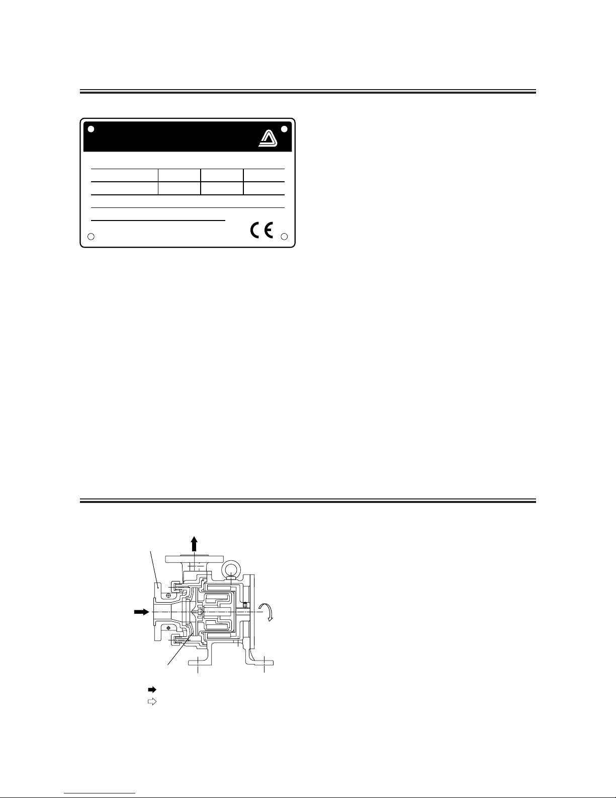
2. Operating Principle
The MDF-L pump is a magnet-driven centrifugal type
pump developed for various applications.
The impeller inside the pump chamber (front casing) is
rotated by magnetic force to transfer liquid from the suction
side to the discharge side.
The MDF-L type pump features excellent corrosion
resistance, durability, and safety, and serves as a chemical
pump for various processes. Most chemicals can be
handled by the pump.
Iwaki Magnet Pump
MODEL
HEAD (m)
CAPACITY (R/ min)
kW
5 0
Hz rpm
MFG.No.
IWAKI EUROPE GmbH
MADE IN JAPAN
MDF - L
Year:
2P406187
: Flow of liquid
: Direction of impeller rotation
Discharge side
Suction side
Impeller
Front casing
Page 10
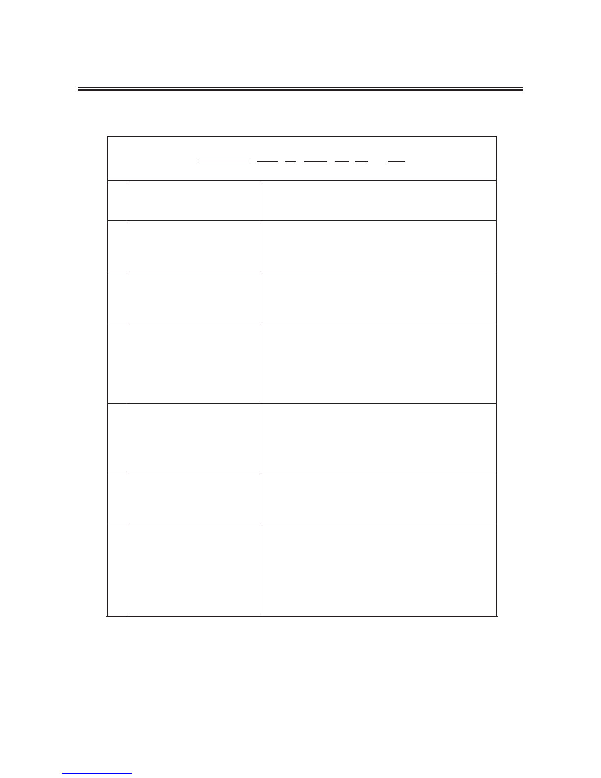
MDF-L Type Series
Shows discharge port diameter
(42 shows 40)
0: 0.37 kW 1: 0.75 kW 2: 1.5 kW 3: 2.2 kW
5: 4 kW 7: 5.5 kW 10: 7.5 kW 15: 11 kW
CF: High density carbon/Alumina ceramics 99.5%
AA: Alumina ceramics 99.5%/Alumina ceramics 99.5%
* SiC/SiC is used in the model 6515.
KK: SiC/SiC
V: FKM E: EPDM A: AFLAS
®
FKM, AFLAS®: Fluoro rubber
EPDM: Ethylene propylene rubber
T, V, W: Standard
K, L: For high head applications
No mark: Standard
D, E: Pin-point contacting bearing system
(Standard models for 250, 401, 422, 423 and
425)
H, DH, EH:For up to 100 ˚C model (call it "H" type)
q Series
w Size of pump:
e Motor output
r Material of bearing/spindle
t Material of O ring and gasket
y Code of impeller
u Construction code
- 8 -
3. Identification Codes
Example:
MDF-L 42 5 CF V T - D
qwertyu
Page 11
- 9 -
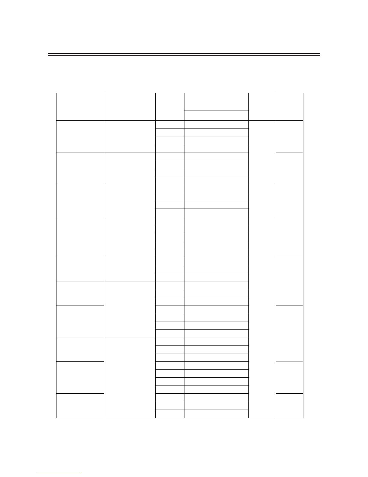
4. Specifications and Outer Dimensions
MM
Standard specifications
25×25
MDF-L401
Port Diameter
Suction Port ×
Discharge Port
Standard Performance
m-R/ min.
Model
Impeller
Code
Rated
speed
(min-1)
Motor
Output
kW
50Hz
K
12.2 - 50
T
7.3 - 150
V
5.6 - 150
W
3.0 - 150
K
16.8 - 100
T
4.5 - 200
V
8.3 - 200
W
4.8 - 200
K
T
V
W
K
L
T
V
W
T
V
W
T
V
W
K
T
V
W
T
V
W
K
T
V
W
T
V
W
40×40
50×40
50
×40
50
×40
65
×50
80
×65
MDF-L250
MDF-L422
MDF-L423
MDF-L505
MDF-L425
MDF-L507
MDF-L657
MDF-L6510
MDF-L6515
20 - 200
18 - 200
14 - 200
10.5 - 200
28.5 - 150
21.5 - 300
19.5 - 300
15 - 300
11.5 - 300
25.5 - 400
21 - 400
12 - 400
17 - 600
12.5 - 600
8.5 - 600
32.5 - 500
29 - 600
19.5 - 600
12.0 - 600
18.5 - 1000
10.5 - 1000
6.5 - 1000
30.5 - 800
26 - 1000
14.8 - 1000
9.5 - 1000
33 - 1000
24.8 - 1000
15 - 1000
2900
0.37
0.75
1.5
2.2
5.5
4
7.5
11
50Hz
Page 12
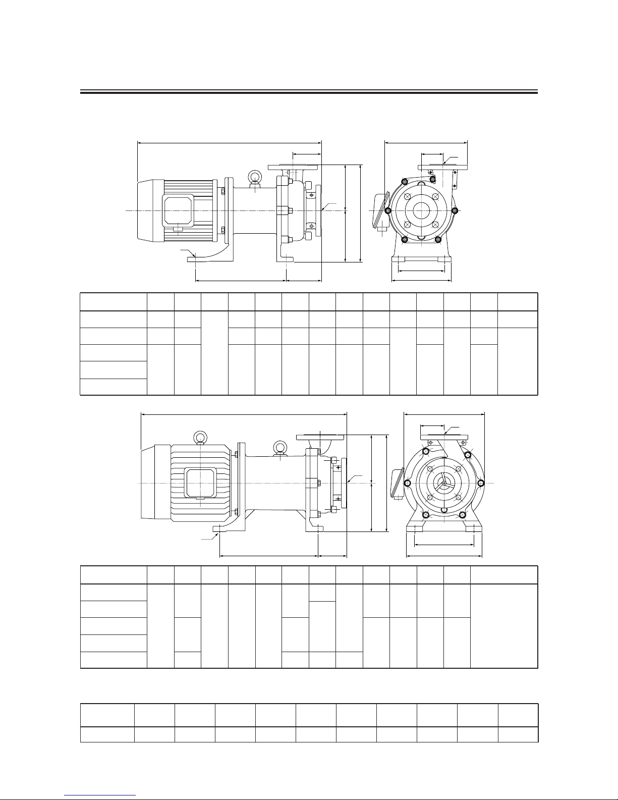
e
a
b
d
g
f
H
j
h
W
i
L
k
Model
Mass (kg)
250 401 422 423 425 505 507 657 6510 6515
- 10 -
Model
MDF-L250
MDF-L401
MDF-L422
MDF-L423
MDF-L425
W
205
233
251
H
237
275
295
L e
143
250
275
d
95
111
106
c
51
58
65
b
150
170
180
a
110
130
140
k
4-ø12
4-ø14
j
25
40
50
i
25
40
h
88
102
87
g
122
140
f
115
135
155
Model
MDF-L505
MDF-L507
MDF-L657
MDF-L6510
MDF-L6515
W
298
H
340
360
410
L f
180
230
e
285
365
450
d
90
108.5
108
b
280
a
220
k
4-ø14
j
65
80
i
50
65
h
80
100
g
160
180
MM
Mass
MM
Outer dimensions
e d
g
f
H
j
h
L
b
a
c
W
i
k
Page 13
- 11 -
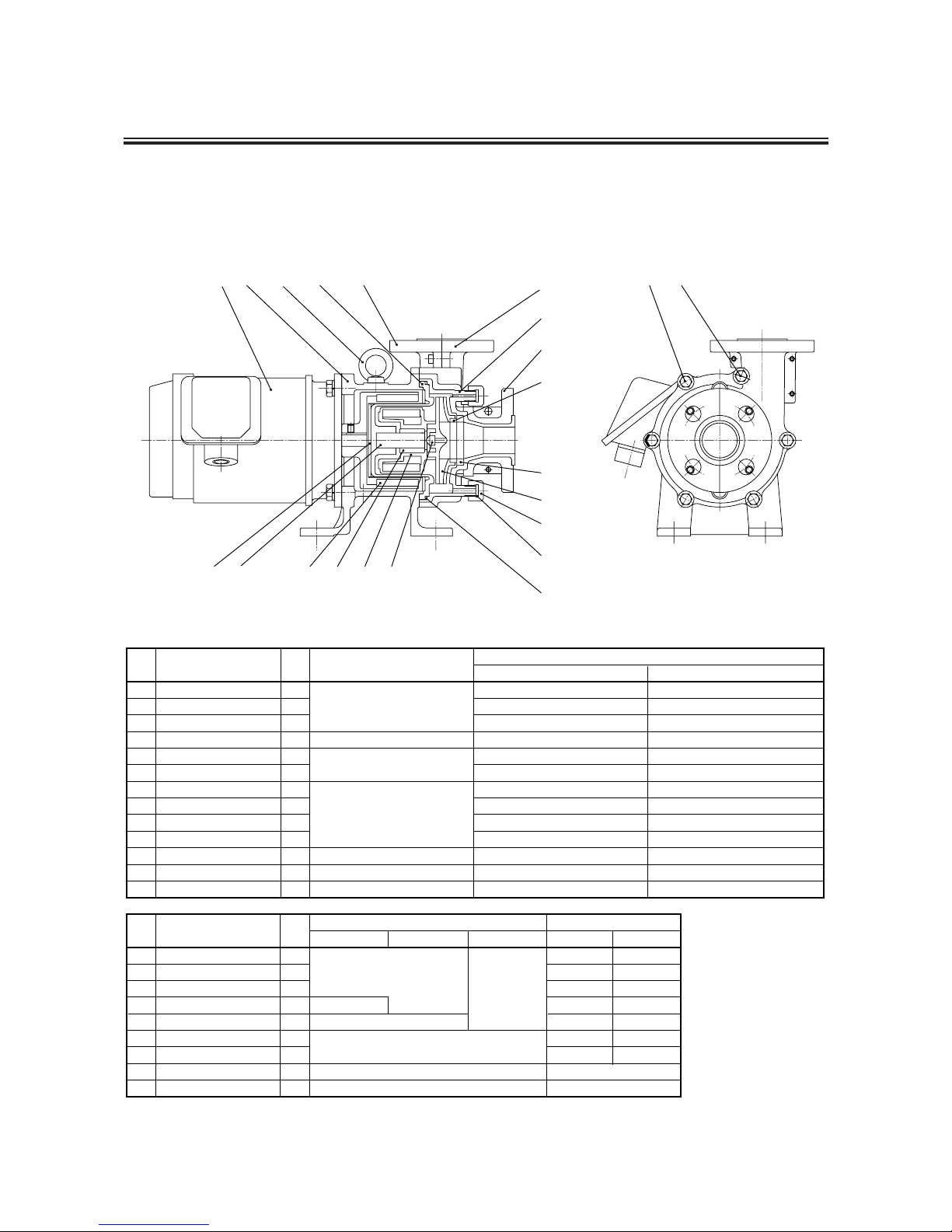
5. Names of Parts
MM
Names of Parts
• MDF-L250 and 401
No.
1
2
3
5
7
8
9
11
12
13
15
16
17
No.
18
19
20
21
22
23
24
25
26
Q'ty
1
1
1
1
1
1
2
1
1
1
2
Parts name
Material
M8×65, WITH SW, Q'TY5
FERRITE MAGNET+ALUMINUM ALLOY
STNLS STL
FC200
CFRETFE
PTFE
CFRETFE
M8×35, WITH SW, Q'TY1
M8×70, WITH SW, Q'TY5
M8×40, WITH SW, Q'TY3
Model 250
Model 401
Remarks
Front casing
Rear casing
Impeller
Drive magnet unit
Hex. head bolt
Hex. head bolt
Foot support
Cover A
Cover C
Cover B
Magnet capsule
Motor
Cap
Q'ty
Parts name
Remarks
Model 401Model 250
JIS B 2401
G 135
Only "H" type
Material
KK-EAA-ECF-D
PTFE
V: FKM E: EPDM A: AFLAS
Steel
STNLS STL
High density
carbon
Alumina ceramics 99.5%
SiC
®
1
1
1
1
1
1
2
1
1
Liner ring
Impeller thrust
Spindle
Bearing
Mouth ring
Oring
Gasket
Eye bolt
Rear casing cover
JIS B 2401
G 160
Only model 401
16
132
25
9
11
1
12
22
18
3
17
24
23
19
15
21520
26
87
Page 14
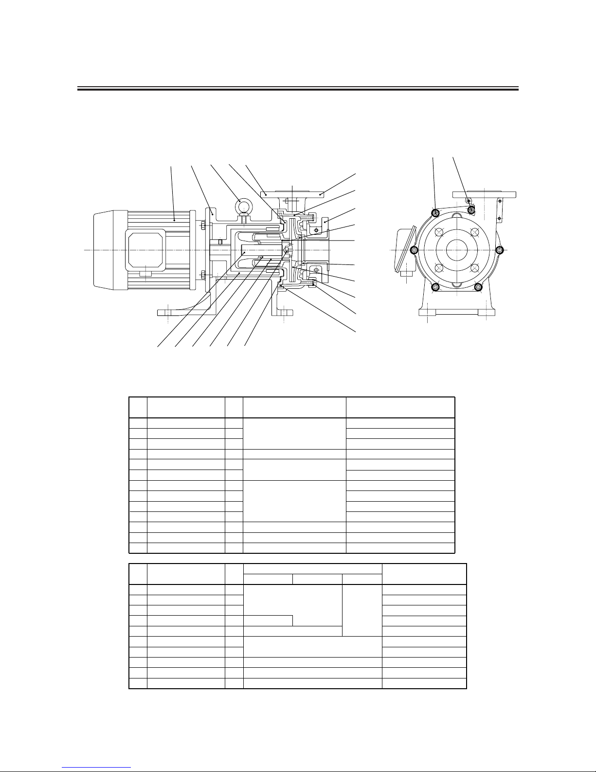
• MDF-L422, 423 and 425
- 12 -
No.
1
2
3
5
7
8
9
11
12
13
15
No.
18
19
20
21
22
23
24
25
29
Q'ty
1
1
1
5
1
1
1
2
1
1
Parts name
Material
M10×40 WITH SW
RARE EARTH MAGNET+FCD450
FC200
CFRETFE
CFRETFE
M10×75 WITH SW
Front casing
Rear casing
Impeller
Drive magnet unit
Hex. socket head bolt
Hex. socket head bolt
Foot support
Cover A
Cover C
Cover B
Magnet capsule
Motor
Cap
Q'ty
Parts name
Remarks
JIS B 2401 G 165
Material
KK-EAA-ECF-D
PTFE
V: FKM E: EPDM A: AFLAS
Steel
STNLS STL
High density
carbon
Alumina ceramics 99.5%
SiC
®
1
1
1
1
1
1
2
1
1
Liner ring
Impeller thrust
Spindle
Bearing
Mouth ring
O ring
Gasket
Eye bolt
Retainer ring
AS568-129
80
V, A: FKM E: EPDM
1
O ring
PTFE
16
17
1
1
2
STNLS STL
Remarks
80
29
87
20 5 211519
16
9
25
2
13
11
1
12
22
23
24
17
3
18
Page 15
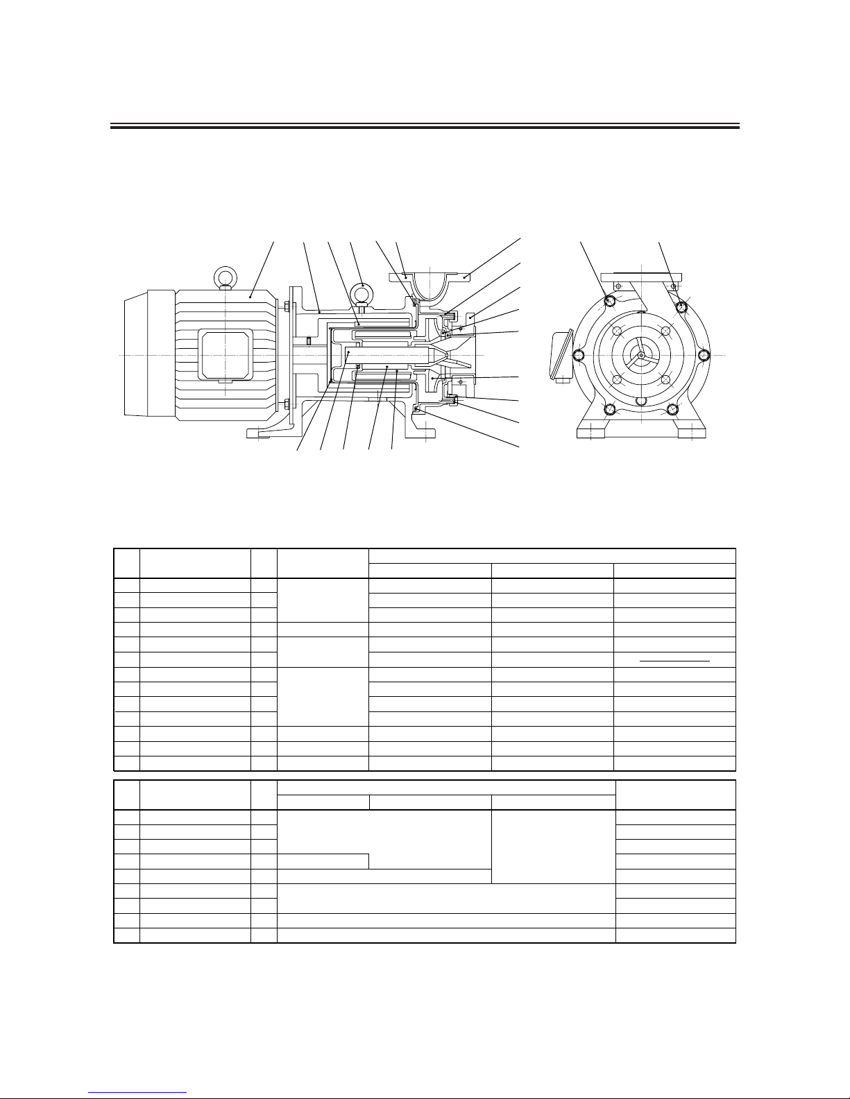
- 13 -
• MDF-L505, 507, 657, 6510 and 6515
No.
1
2
3
5
7
8
9
11
12
13
15
No.
18
19
20
21
22
23
24
25
26
Q'ty
1
1
1
1
1
2
1
1
Parts name
Material
M12×50, WITH SW, Q'TY 5
FERRITE+SS400
FC200
CFRETFE
CFRETFE
M12×90, WITH SW, Q'TY 1
Model 505 and 507
Remarks
Front casing
Rear casing
Impeller
Drive magnet unit
Hex. head bolt
Hex. head bolt
Foot support
Cover A
Cover C
Cover B
Magnet capsule
Motor
Cap
Q'ty
Parts name
Remarks
JIS B 2401 G 230
Material
KKAACF
Alumina ceramics 99.5%
PTFE
V: FKM E: EPDM A: AFLAS
Steel
STNLS STL
High density carbon
SiC
®
1
1
1
1
1
1
2
1
1
Liner ring
Rear thrust ring
Spindle
Bearing
Mouth ring
O ring
Gasket
Eye bolt
Rear casing cover
PTFE
16
17
1
1
2
STNLS STL
M12×50, WITH SW, Q'TY 5
M12×100, WITH SW, Q'TY 1
Model 657 and 6510 Model 6515
M12×90, WITH SW, Q'TY 6
*
Note: In model 6515 AA, Spindle and Bearing made of SiC are used.
Model 505 has a rear casing cover only "H" type.
The larger models above model 507 have a rear casing cover as standard equipment.
In model 6515, Drive magnet made of rare earth magnet is used.
2026
16 9 5 25 2 13
8
7
19 21 15
23
24
17
3
11
1
12
22
18
Page 16

MM
Description on Main Unit Body and Label
- 14 -
Pump unit (liquid feeding section)
Non-self priming type: Before operating the
pump, feed priming
liquid through the
suction or dischargeside
port.
Motor nameplate
Use only the power voltage specified on the
nameplate. (Follow applicable local power
regulations when used outside of Japan.)
"Arrow" indicator label
The arrow indicates the rotating
direction of the motor.
Always make sure that the motor
runs in the direction the arrow
indicates. (Refer to Preparation
for start-up [6] in the Pump
operation chapter.)
Motor (Driving section)
This motor provides power to the
pump unit.
Base
Setting should be fixed.
Discharge port
Suction port
Drain port
Liquid discharge port
Drain the discharged liquid into a
suitable container and follow the
applicable local regulations in
disposing of the liquid. Never
allow the discharged liquid to run
directly onto the ground.
"Never Operate Dry" indicator label
Operating the pump without liquid will
cause damage inside the pump. Never
operate the pump without liquid.
CAUTION
When cleaning the pump, be careful not to wipe the labels or the pump body
with solvent.
Specifications nameplate
Pump must be operated only under
the specified conditions.
Page 17

PUMP OPERATION
1. Handling Instructions ...................... 16
2. Installation ....................................... 21
3. Piping .............................................. 22
4. Wiring .............................................. 26
5. Operation Step ............................... 27
- 15 -
Page 18

[1] Handle the pump carefully.
Strong impacts caused by dropping the pump on the floor or striking it may result in damage or faulty
performance.
[2] Priming water
Be sure to fill the pump unit with feeding liquid as priming water before pump operation.
[3] Do not operate the pump in the following places.
• Places where the temperature falls below 0 ˚C
• Places where corrosive gas or explosive gas is generated
• Places exposed to splashing water
• Places where the ambient temperature is 40 ˚C or above
• Places where the humidity is excessively high. (Permissible humidity: 35~85%RH)
• Places filled with or likely to be filled with explosive or corrosive atmosphere.
• Danger due to dust, fire, earthquake and/or any externally imposed shock.
[4] Keep the pump away from fire.
To prevent fire and explosions, do not place dangerous or inflammable substances near the pump.
[5] If pump is damaged
Do not operate a damaged pump, otherwise there may be electricity leakage or electric shocks.
(Observe all the following instructions
to prevent injuries and accidents.)
- 16 -
1. Handling Instructions
Caution
¡Read the following information prior to installing the pump.
¡Protective wear:
When operating the pump or working near it, with the pump system loaded with chemical liquid,
always wear protective clothing, face guard, goggles, and gloves. Further precautionary
measures must be taken depending upon the type of liquid used.
¡Operating the pump dry (without supplying liquid to it) may cause seizure on wear of the
inside of the pump section.
¡Do not repair the pump beyond the range specified in this instruction manual.
The pump must be repaired by trained and qualified operators only.
Page 19

[6] No remodeling
Never try to remodel the pump. This may cause a serious accident or damage.
[7] Limitation to disassembly or repair
Users are allowed to disassemble and repair the pump to the degree of the given description in "Disassembly
and Assembly" in this manual.
[8] No dry running operation
Dry operation of the pump (pump operation without liquid inside) may cause damage to the pump internally.
Never operate the pump dry. In the case of MDF-L type, the sliding parts are self-lubricated and self-cooled. If
the pump is operated dry or with the suction-side valve closed, damage may result.
* Countermeasures to be taken in case of dry operation
1. Turn off the power switch of the pump immediately and leave the pump as it is for more than 1 hour.
2. Prime the pump and fill the pump with liquid.
(Note that the pump should be supplied with liquid after leaving the pump empty for more than 1 hour.
Sudden supply of liquid may cause a crack in a part due to quenching effects.)
[9] Dry operation compatible type pump
The dry running operation compatible type pump (with D at the end of the model identification) can endure
continuous dry running operation of not longer than 1 hour. Longer dry running operations, if repeated
frequently, may result in wear of the sliding parts which rapidly affects the normal functioning of the inner part
of the pump. The pump is designed so as not to develop cracks as a result of sudden cooling down with liquid
immediately after dry operation. However, it is recommended that the pump be left as it is for about 20 minutes
before running it with liquid.
* Pumps with E at the end of the model identification or without any symbol cannot endure dry running
operation.
[10] Points to be noted when starting and stopping pump
Pay close attention to the following points to avoid water hammer action when starting and stopping pump
operation. When the discharge-side piping is very long, extra attention is required.
(1) When starting the pump, first prime it. Then, close the discharge valve completely and turn on the power
switch. After starting up the pump, open the discharge valve gradually and set it to the desired operation
level.
(2) When stopping the pump, first close the discharge valve slowly. Turn off the power switch only after
completely closing the discharge valve.
In this procedure, never try to stop the pump quickly using a solenoid
valve, etc. Quick closure may cause water hammer action, and the
excessive pressure will destroy the pump.
- 17 -
Caution
Page 20

505 "H" type
507/657/6510 Standard
[11] Allowable pressure limit
See the table 1~5 for allowable pressure limits of each model.
See that the discharge pressure does not exceed the allowable pressure limit.
- 18 -
425 Standard
"H" type
MDF-L250
Standard
0.3
0.16
MPa
0 ˚C 90 100
Temperature
MDF-L422/423/425
0.45
0.4
MPa
0 ˚C 100
Temperature
422/423
Standard
"H" type
MDF-L401
Standard
0.3
0.24
MPa
0 ˚C 90 100
Temperature
MDF-L505/507/657/6510
0.5
0.4
0.3
MPa
0 ˚C 70 90 100
Temperature
Table 1
Table 4Table 3
Table 2
NOTE
MDF-L6515
0.6
0.5
MPa
0 ˚C 70 100
Temperature
Standard
Table 5
NOTE
*AFLAS®O ring
Above 10 ˚C
505 Standard
Page 21

[12] Use of slurry liquid
In principle, slurry liquid pumping is not possible. However, pumps with ceramic bearings (AA, and KK types
only) can handle the pumping of slurry liquid with a density of 5wt% or less, grain size of 50 µm or less, and
hardness of 80Hs or less. Prior to pumping such slurry liquid, be sure to confirm the operation feasibility with
the supplier.
[13] Influence of specific gravity and viscosity of liquid on pump performance
If the specific gravity or viscosity of the liquid is higher than that of pure water, the shaft power, discharge
volume, and pump head may vary somewhat. The delivered pump has been prepared to meet the specifications
ordered by the user. To change the operating conditions after delivery, be sure to contact the supplier.
[14] Intermittent operation
Frequent start/stop switching considerably shortens the service life of the pump. Try to limit the switching
frequency to six times or less per hour.
[15] Temperature humidity fluctuation
Temperature fluctuation may not change the performance of the pump itself. However, the liquid may change
in terms of its viscosity, pressure, or corrosion resistance. Pay special attention to changes in liquid
characteristics as a result of temperature fluctuation.
* The liquid temperature range for the pump using the O ring supplied by AFLAS®is 10~90 ˚C.
* Refer to the corrosion resistance table for the temperature ranges recommended for various types of liquid.
For inquiries or consultation, contact the dealer you placed your order with.
* Some types of pumps can be operated in the temperature range of 90~100 ˚C. For details, contact your
dealer.
[16] Disengagement of magnet coupling
Though the motor is running, the liquid is not circulated. (The pressure gauge on the discharge side points to "0"
point approximately.)
When the magnet coupling disconnects, stop the pump within 1 minute. If operation is continued with the
coupling in the disconnected mode, the power of the coupling will decrease considerably.
[17] Removal of grease (For AA type only)
Fluorocarbon grease is applied over the bearing in the AA type pump. The grease may, depending on the type
of liquid, melt into the liquid. Contact your dealer if you do not want the application liquid to be mixed with the
grease.
- 19 -
Liquid temperature range: 0~100 ˚C (pure water)
< 90~100 ˚C for the model MDF-L 250, 401 and 505 with code symbol "-H", "-EH", or "-DH" >
Ambient temperature range: 0~40 ˚C
Humidity range: 35~85%RH
Page 22

[18] Operation within range of drooping head capacity curve
In the case of a pump which generates a drooping head capacity curve in a low-capacity range, do not operate
the pump in the section where the line droops to the left. (Refer to the standard performance curve to verify the
head capacity.) If the drooping section (left side) of the head capacity curve is part of the pump operation
specifications, design the piping with the following points in mind.
q The discharge piping should have no water tank or air trap.
w The discharge amount should be adjusted with the valve installed near the discharge port.
- 20 -
Page 23

2. Installation
- 21 -
[1] Installation position
• Install the pump as close to the suction tank as possible and in the lowest position available (for flooded
suction).
• If the suction port of the pump is to be positioned higher than the suction tank (for suction lift), be sure to
arrange for a foot valve in the priming pipe and suction pipe.
* The lift head depends upon the liquid properties, temperature, and length of the suction piping. For details of
the setup, consult IWAKI or your dealer.
[2] Indoor and outdoor use
The pump can be operated either indoors or outdoors. However, safety measures should be taken so as not to
expose the motor and power distribution unit to flooding or other natural hazards.
[3] Installation site
Select an installation site that is flat and free of vibrations caused by nearby machines. Space sufficient for
maintenance work should be provided.
M Lifting
When lifting the pump, please pay attention to the following points.
• Pump must be lifted horizontally using two bolts located at pump and motor.
• In the case that there is no lifting bolt at the motor, rope or such kind materials should be tightenly winded to the
motor to lift the pump horizontally.
• Please use lifting chain or rope which has enough strength enduring pump weight.
• To prevent any human body accident caused by the pump drop, please do not enter under the lifted pump.
M Foundation preparation (before pump installation)
[1] The area for anchoring the pump must be greater than the area of the base. If the anchoring area is not enough,
the base may be destroyed due to a concentrated load on it.
[2] If pump operation is to be subject to vibration (resonation with the piping, for example), provide an expansion
joint between the pump and the piping. Otherwise, the piping, gauge, etc., may be damaged.
[3] Installation advice
• Use anchor bolts to fasten the pump base firmly.
• Install the pump horizontally.
• Sufficient space is required to allow cool air from the motor fan to circulate.
• Allow ample space around the pump for easy and efficient maintenance work.
Page 24

Tightening torque for piping flange of pump. (In the cace of steel flange with rubber gasket.)
Recomended bolt size and tightening torque for piping flange are as follows.
MDF-L250 : Bolt size is M12 and tightening torque is 42 N·m.
MDF-L401, 422, 423, 425, 505, 507, 657, 6510 and 6515 : Bolt size is M16 and tightening torque is 78.4
N·m.
Load of piping and momentum of piping for MDF-L.
The permissible stress and moment applicable to pump connection arrangement are as shown below.
The piping should be designed and worked so that stress and moment, higher than those values indicated in the table,
should not be applied to the pump.
Z
X
Y
X
Z
Y
3. Piping
- 22 -
Table 9 : Piping loadings
Forces of discharge piping Forces of suction piping
Direction of load
Mx
My
Mz
Direction of load
Fx
Fy
Fz
kN
0.89
0.58
0.71
kN
1.33
0.89
1.07
Dia. of pipe
25, 40, 50 65, 80
Load
kN·m
0.46
0.35
0.23
kN·m
0.95
0.72
0.47
Dia. of pipe
25, 40, 50 65, 80
Load
Direction of load
Fx
Fy: compression
Fy: tension
Fz
kN
0.71
0.89
0.44
0.58
kN
1.07
1.33
0.67
0.89
Dia. of pipe
25, 40, 50 65
Load
Mx
My
Mz
Direction of load
kN·m
0.35
0.46
0.23
kN·m
0.72
0.95
0.47
Dia. of pipe
25, 40, 50 65
Load
Moments of discharge piping Moments of suction piping
Page 25

- 23 -
Example of piping
(1) Discharge pipe (Support the pipe to keep the
pump free of piping load.)
(2) Valve
(3) Check valve
(4) Pressure gauge
(5) Motor
(6) Pump
(7) Air vent pipe
(9) Drain ditch
(10) Vacuum gauge
(11) Suction pipe (pipe diameter: D)
(The horizontal section should be as short as
possible and there should be an ascending
gradient of 1/100 toward the pump.)
(12) Pipe support
(13) Pump drain
(14) Suction pipe (pipe diameter: D)
(15) 2D, 500 mm or above
(16) Expansion joint
(17) Piping for flushing (Discharge side)
(18) Piping for flushing (Suction side)
15
1
2
12
3
4
12
16
5
6
7
2
17
2
1011
12
2
14
16 13
18
2
9
Page 26

Good
No good
Good
Good conditions Unacceptable conditions
No good
Good
No good
Good
No good
Air trap
Air trap
- 24 -
M Suction piping
[1] The suction pipe should employ the flooded suction method if possible. The shortest pipe possible, with the
minimum number of bends, should be used. Arrange a proper support under the suction pipe such as an
expansion joint or the like so that the weight and thermal stress of the pipe are not applied to the pump.
[2] Attach the coupling on the suction pipe carefully so as not to allow air inside the line. Air in the suction pipe
may damage the system.
[3] If suction is not good (e.g., the suction tank is a vacuum, the suction head is large, or the suction pipe is long),
the condition NPSHa > NPSHr + 0.5 m should be established. For the NPSHr level, refer to the standard
performance curve.
[4] When using an elbow pipe on the suction side, install a straight pipe with a length of at least 500 mm or 8 times
the suction port diameter before the pump suction port. Provide the largest radius possible for the R of the bend.
[5] Do not allow any projection where air may be trapped along the suction pipe. The suction pipe should have an
ascending gradient of 1/100 toward the pump.
Air trap
Air trap
Page 27

- 25 -
[6] If the diameters of the pump suction port and the suction pipe are different, use an eccentric reducer pipe.
Connect the eccentric reducer pipe so that the upper surface is level. In any case, never use a suction pipe with a
diameter smaller than that of the suction port.
[7] It is also recommended, in the case of flooded suction, that a gate valve be installed on the suction pipe for
easier overhaul inspection of the pump. Keep the gate valve fully open during ordinary pump operation; it is
required to be closed only during an overhaul inspection.
[8] When circulating a dangerous liquid, arrange the flushing pipes so that internal cleaning is possible when
disassembling the pump.
[9] The diameter of the suction pipe must be larger than that of the pump suction port.
[10] The end of the suction pipe should be located 500 mm or more below the surface of the liquid.
[11] A screen should be provided at the inlet in the suction tank to prevent the entry of foreign matter into the suction
pipe. The end of the suction pipe should be 1~1.5 D (D: diameter of suction pipe) or more away from the
bottom of the suction tank. Note that the entry of foreign matter may cause the pump to malfunction.
[12] In the case of the suction lift method, install a foot valve on the suction pipe.
Note: The items [10], [11], and [12] above are applied to the suction lift method.
M Discharge piping
[1] Use a support so that the weight of the pipe is not applied to the pump as load.
[2] If a method other than flooded suction is employed, install a priming pipe.
[3] If the pipe is too long the piping resistance may increase, hampering the pump's performance. The diameter of
the pipe should be determined by calculating the piping resistance.
[4] A check valve should be installed if any one of the following conditions is present. When selecting the check
valve, consider the check valve pressure limit (including the influence of water hammer or back flow onto the
pump).
q The discharge piping is very long
w The discharge lift exceeds 15 m
e The end of the discharge pipe is 9 m higher than the surface of the suction tank
r Several pumps are connected parallel to one another on the same piping
Page 28

[5] It is recommended that a valve be installed on the discharge pipe for the adjustment of discharge volume and for
the prevention of overload onto the motor. When installing both a check valve and a valve, the check valve
should be positioned between the pump and the valve.
[6] Do not fail to install a pressure gauge on the discharge piping.
[7] Install an air bleeding valve if the discharge pipe is very long horizontally.
[8] Install a drain valve for the drainage of liquid if there is a chance that the liquid in the discharge pipe might
freeze.
- 26 -
[1] Use an electromagnetic switch that conforms with the specifications (voltage, capacity, etc.) of the pump motor.
[2] If using the pump outdoors, waterproof the wiring to protect the switches from rainwater.
[3] Electromagnetic switches and push buttons should be installed reasonably distant from the pump.
[4] For starting up a pump with a motor of 5.5 kW or higher, be sure to use a Star Delta starter, soft starter or
invertor.
*Refer to the instruction manual of the motor issued by the motor maker for detailed handling instructions.
Electrical connections
ATTENTION
The electrical connection should be carried out by an authorized electrician in accordance with
local regulations. Please make sure that the electrical data on the nameplate of the motor
correspond to the electricity supply on which it will be used. Motors must be connected to a motor
protection switch.
4. Wiring
Page 29

5. Operation Step
M Operation instructions
[1] Never operate the pump dry or with the suction-side valve closed. Otherwise, the inside of the pump will be
damaged.
[2] In the event of cavitation, stop the pump within a minute.
In addition, do not continue pump operation with the air mixed into the suction side.
[3] If the magnet coupling disconnects, stop the pump within a minute. The power of the magnet coupling is
reduced if operation is continued with the coupling disconnected.
[4] The temperature fluctuation should not exceed 80 ˚C through the operation modes of starting, stopping, and
operating the pump.
[5] Before starting operation, close the discharge valve fully to prevent water hammer action upon start-up.
[6] Note that pump operation with the discharge valve closed fully over a long time will raise the temperature of the
liquid inside the pump and finally damage the pump.
[7] In the event of a service power failure, turn off the power switch immediately and close the discharge valve.
[8] Make sure that intolerable pressure levels are not applied to the pump. Refer to "page 18 [11] Allowable
pressure limit" in "1. Handling Instruction."
[9] Maximum pump surface temperature
The max. pump surface temperature of each model is shown in the table. Arrange protective measures in
accordance with the temperature levels.
- 27 -
Maximum surface temperature
when ambient temperature
is at 40 ˚C. (˚C)
MDF-L250
401
422, 423, 425
505, 507
657, 6510
6515
Model
Liquid temp (˚C)
100
90
90
90
90
90
95
2900
Rated speed
(min
-1
)
Page 30

[10] Sound generated by pump
The level of sound generated by each type of pump is shown in the table. Arrange a muffling measures in
accordance with the sound level. The procedure for sound measurement conforms to the EN 31201 (ISO11201).
- 28 -
(dB)
M Preparation for start-up
Preparations should be made, as described below, in the case of initial operation after installation and in the case of
restarting of operation after a long period of inactivity.
[1] Thoroughly clean the inside of the pump and pipe. Then, supply liquid.
[2] Tighten the flange connecting bolts and the installation bolts on the base.
[3] After priming the pump, close the discharge valve fully.
Also, make sure the air-vent valve and flushing piping valve are closed.
[4] In the case of the flooded suction method, measure the pressure in the flood pipe to confirm that the pump is
filled with liquid.
[5] In the case of the suction lift method, prime the pump.
[6] Run the motor instantaneously to check for correct direction of motor rotation. The motor should run in the
direction indicated with the arrow on the pump. If the direction is reversed, exchange any two wires of the
three-phase power wires.
Model
Sound
Level
MDF-L2507540180422, 423, 42580505, 50780657, 6510856515
85
Page 31

Points to be observed during operation.
If pump enters continuous operation mode, check flow
meter and confirm that pump operation is as per
specifications.
Remarks
• Suction valve-Fully opened
• Discharge valve-Fully opened
• Confirm pump is filled with liquid. If pump is not filled
with liquid, fill it in accordance with steps [4] and [5] of
'Preparation for start-up'. After priming completely,
close the discharge valve fully.
• Supply power immediately to run the pump only when
checking the rotating direction of the pump. (Correct
direction of pump operation is indicated with arrow on
the pump. Check the direction of motor fan by looking
at the fan through the fan cover.)
• Observe carefully to see if the motor fan slowly and
smoothly stops rotating when the power switch is turned
off.
Note: If the motor fan does not stop smoothly, it is
possible that the pump is locked inside.
In this case, contact your IWAKI dealer.
• Open valve carefully while paying attention to
amperemeter, to prevent motor from being overloaded
from excessive opening of valve.
* Within 1 minute, open the discharge valve gradually and
adjust the discharge pressure while checking the reading
of the pressure gauge on the discharge side. (Otherwise,
adjust the flow rate while checking the reading of the
flowrate meter.)
Caution
Total discharge pressure is increased to shut-off
pressure after start of normal pump operation,
open discharge valve gradually to set.
Operation Step
• Close or open the valve.
• Prime the pump
• Check the motor for correct rotating direction.
Switch on the power and then immediately switch off the
power.
• Turn on the power and start the pump. Then, adjust the
discharge pressure and discharge volume.
Following discharge volumes should be noted during pump operation.
MDF-L250 and 401: 10r/min. or above
MDF-L422 and 423: 20r/min. or above
MDF-L425, 505, 507, 657, 6510, and 6515: 50r/min. or above
• In case of automatic drive, too, close discharge valve before start-up and open valve slowly after start-up.
Caution
Do not run pump longer than 1 minute against a fully closed discharge valve.
M Operation
Operate the pump by following the steps given below.
- 29 -
No
1
2
3
4
• If flow meter is not available, check the values of
discharge pressure, suction pressure, and electric current
with reference to piping resistance.
5
Page 32

3 Points to be observed when stopping pump
• If the pump operation is stopped during cold weather, liquid in pump may freeze and damage pump. When
circulating a dangerous liquid, carry out internal cleaning by using flushing piping. Then drain the liquid
fully.
• Be sure to remove all liquid after stopping pump. In case of short-term suspension of operation, which
does not allow for removal of liquid, use band heater, etc., to prevent liquid inside from freezing.
• In event of power failure, turn off power switch and close discharge valve.
M Stoppage
- 30 -
1
2
Check/Operation Step
• Close discharge valve gradually.
• Turn off the power and stop pump operation.
Remarks
• Do not cause sudden closure with solenoid valve,
etc., otherwise pump may be destroyed by water
hammer action which is likely in case of long
discharge piping.
• Observe carefully whether the motor fan slowly
and smoothly stops rotating.
Caution
If not, check inside of pump.
Page 33

MAINTENANCE
1. Causes of Trouble
and Troubleshooting ........................ 32
2. Maintenance and Inspection ........... 35
3. Spare Parts ..................................... 39
4. Disassembly and Assembly ............ 40
- 31 -
Page 34

1. Causes of Trouble and Troubleshooting
- 32 -
Problem
Liquid is not
lifted.
Discharge
volume is
small.
When Discharge
Valve is Opened
Pressure gauge
and vacuum
gauge indicate
‘zero’.
Points of
pressure gauge
and vacuum
gauge swing
but return to
zero at once.
Pointer of
vacuum gauge
indicates a high
value.
When Discharge
Valve is Closed
Water goes
down at once
when priming
is carried out.
Pressure is
reduced if
discharge valve
is opened after
start-up step.
Pointer of
pressure gauge
never rises.
Cause
K Not enough priming wa-
ter
K Dry operation.
K Foreign matter is clog-
ging foot valve.
K Air enters through suction
pipe or gasket section.
K Magnet coupling has dis-
connected.
K Speed of pump is too low.
K Pump rotates in reverse
direction.
K Strainer is clogged with
foreign matter and liquid
passage is blocked.
Inspection and Measures
K Stop pump, feed sufficient
priming water, and restart
pump.
K Clean foot valve.
K Check whether seat is clogged
with foreign matter.
K Check again whether conn-
ecting flange in suction piping
is sealed airtight.
K Check whether suction liquid
level is abnormally lowered.
K Measure electric current level
to check for overload condition.
K Check whether the voltage
level is normal.
K Check for foreign matter
between impeller and casing.
K Check wiring and motor and
make necessary repairs.
K Exchange wires.
K Eliminate the foreign matter in
strainer.
Symptom on pump
Refer to "1. Causes of Trouble and Troubleshooting". Consult supplier for more information.
If you find any troubles, turn off the power supply immediately.
Page 35

- 33 -
Problem
Discharge
volume is
small.
When Discharge
Valve is Closed
Pointers of
pressure gauge
and vacuum
gauge indicate
normal values.
Pointer of
pressure gauge
indicates low
value and that
of vacuum
gauge indicates
extraordinarily
low value.
When Discharge
Valve is Opened
Pointer of
vacuum gauge
indicates
extraordinarily
high value.
Pointers of
pressure gauge
and vacuum
gauge swing.
Pointer of
vacuum gauge
indicates a high
value while
that of pressure
gauge indicates
normal value.
Pointer of
pressure gauge
indicates high
value while
that of vacuum
gauge indicates
normal value.
Pointers of
pressure gauge
and vacuum
gauge indicate
low values.
Cause
K Air is trapped in suction
pipe.
K Inlet section of impeller
unit is clogged with
foreign matter.
K Air enters through suction
pipe or gasket section.
K Discharge side of pump is
clogged with foreign
matter.
K There is an air trap or
resistance in suction pipe.
K There is portion in dis-
charge pipe that causes
resistance, or actual head
and loss of head are too
high.
K Rotation direction is re-
versed.
Inspection and
Countermeasures
K Inspect setup condition of
suction pipe and modify it if
necessary.
K Disassemble unit partially and
eliminate foreign matter.
K Check connecting section of
suction pipe and tighten it if
necessary.
K Eliminate foreign matter in the
pump.
K Eliminate foreign matter or
scale inside pipe.
K Check whether there is
protruding section in suction
pipe and take necessary
measures.
K Check actual head and piping
loss of discharge pipe and take
necessary measures.
K Exchange wires.
Symptom
Page 36

- 34 -
Problem
Motor is
overheated.
Discharge
volume is
suddenly
lowered.
Pump
vibrates.
When Discharge
Valve is Closed
When Discharge
Valve is Opened
Pointer of
vacuum gauge
indicates high
value.
Cause
K Voltage is lowered.
K Overload.
K Ambient temperature is
high.
K Strainer is clogged with
foreign matter.
K Foundation is defective.
K Anchor bolt is loose.
K Suction pipe is closed.
Cavitation is caused.
K Wear or melting of pump
bearing.
K Magnet capsule or spindle
is damaged.
K Dynamic balance of drive
magnet assembly fluctuates.
K Impeller and/or magnet
capsule is in contact with
fixing section.
K Wear of motor bearing.
Inspection and
Countermeasures
K Check whether the voltage and
frequency levels are adequate.
K Check whether the specific
gravity and viscosity of liquid
are adequate.
K Improve air ventilation.
K Eliminate foreign matter.
K Reinstall.
K Retighten bolts.
K Clean, and eliminate cause of
cavitation.
K Replace.
K Replace.
K Eliminate cause or replace.
K Replace.
K Replace bearing or motor.
Symptom
Page 37

2. Maintenance and Inspection
M Daily inspection
[1] Check whether the pump operates smoothly, without generating any abnormal noise or vibration.
[2] Check the level of the liquid in the suction tank and the suction pressure.
[3] Compare the discharge pressure and electric current measured during operation with the values indicated on the
motor nameplate for the verification of normal pump load.
* Note that the values indicated on the pressure gauge vary in proportion to the specific gravity of the liquid.
The cock of the pressure gauge or vacuum gauge must be opened only when measurement is carried out. It
must be closed upon the completion of each measurement. If the cock remains open during pump operation,
the meter mechanism may be affected by abnormal pressure caused by water hammer action.
[4] If a spare pump is available, activate it from time to time to keep it ready for use any time.
[5] Check to be sure there is no liquid leakage in the pump before operating it. If leakage is detected, never try to
operate the pump.
[6] Check to be sure the discharge pressure, discharge flow rate, and motor power supply voltage do not fluctuate
during pump operation. If considerable fluctuation of the respective values occurs, refer to "1. Causes of
Trouble and Troubleshooting" for correct measures.
M Periodic inspection
To ensure efficient and smooth operation of the pump, carry out periodic inspections by the following procedures
described below.
The overhauling and repair work for IWAKI pumps must be performed by qualified and trained personnel. User’s
failure to observe this instruction exempts IWAKI from the responsibility for personal injury or damage to the
equipment or facility which result from its misuse.
- 35 -
Page 38

Every 6 months
* Inspection record
should be kept.
Inspection Timing
- 36 -
Part Name
Drive magnet unit
Rear casing
Magnet capsule
Impeller
Front casing
Spindle
Check Points
K Are there slide-scratches?
K Is housing fixed normally? Is hex. socket set screw loose?
K Are inner perimeter of magnet and motor shaft coaxial?
(Max. eccentricity: 1/10 mm)
K Are there slide-scratches in bore?
K Are there cracks on liquid end part?
K Wear of thrust ring.
K Wear of spindle tip. (MDF-L 250, 401, 422, 423 and 425)
K Stains in rear casing.
K Are there a slide-scratches in the rear section or in the
cylindrical body?
K Are there cracks in resin of rear section or in cylindrical
body?
K Wear of bearing. (Measure dimensions.)
K Condition of fixed with impeller.
K Wear of mouth ring. (Measure dimensions.)
K Wear of impeller thrust. (MDF-L 250, 401, 422, 423 and
425)
K Are there cracks?
K Are there cavitation marks (such as mouth ring condition,
wear, seizure)?
K Stains or clogging inside impeller.
K Dimensional change in impeller.
K Stains in liquid contacting part.
K Are there cracks?
K Are there wear, slide-scratches, or cracks in thrust ring?
K Is drain clogged?
K Are there expansion or cracks on O ring?
K Slide-scratches in unlikely position.
K Are there cracks?
K Wear of abrasive section.
Page 39

* If the difference between the inner diameter of the bearing and the outer diameter of the spindle exceeds 1 mm, either
the bearing or the spindle whichever has the greater wear, should be replaced regardless of the values in the above
table. In the case of a ceramic bearing type pump, the spindle and the bearing should be replaced simultaneously.
* Initial wear may appear in the sliding parts in the first stages of operation. This should not be mistaken for an
abnormal condition.
M Wear limit of mouth ring
M Wear limits of bearing and spindle
Unit: mm
- 37 -
Model
Part
Inner diameter
of bearing
Outer diameter
of spindle
MDF-L
250
Upon
Shipment
18
18
Upon
Replace-
ment
19
17
MDF-L
401, 422
423, 425
Upon
Ship-
ment
26
26
Upon
Replace-
ment
27
25
MDF-L
505
Upon
Shipment
28
28
Upon
Replace-
ment
29
27
MDF-L
507, 657, 6510
Upon
Ship-ment
36
36
Upon
Replace-ment
37
35
MDF-L
6515
Upon
Shipment
34
34
Upon
Replace-
ment
35
33
Upon Shipment 2 mm
Mouth ring
Impeller
MDF-L505, 507, 657,
6510, 6515
9
7
Model
Thickness upon shipment
Thickness upon replacement
MDF-L250, 401, 422,
423, 425
8
6
* The step between the surfaces of the mouth ring and the impeller upon shipment is 2 mm. The wear limit of the
mouth ring is reached when this step is reduced to 0 mm. Replace the mouth ring then.
Unit: mm
Page 40

M Wear limits of tips of impeller thrust and spindle
(only for pumps with D or E at the end of model identification)
Pumps whose model identification codes have D or E at the end are designed to result in contact between the impeller
thrust tip and the spindle tip in the event of an abnormal operating condition (cavitation, dry operation, etc.). If the tips
are worn out beyond the wear limit level, the pump is subject to serious damage. The condition of the tips in contact
must be checked if an abnormal profile such as dry operation or cavitation lasts a total of over 3 hours.
- 38 -
M Wear checking steps
[1] Remove the rear casing from the foot support
and insert the magnet capsule attached to
impeller can into the rear casing.
[2] Rotate the impeller slowly by hand, with it
positioned on the rear casing.
• Tips are not worn out beyond wear limit
The impeller and magnet capsule will continue
to rotate smoothly.
• Tips are worn out beyond wear limit
The impeller and magnet capsule will not
continue to rotate smoothly. The contact at the
A section or B section, as shown in the figure of
the left, does not allow for the continuous
smooth rotation of the impeller and the magnet
capsule because the tips of the two elements are
excessively worn. In this case, replace the
impeller and rear casing with new ones.
Foot support
Rear casing
Impeller
Impeller thrust
A section
B section
Spindle
Rear casing
Magnet capsule
Page 41

3. Spare Parts
Appropriate spare parts are necessary to ensure long, continuous operation of the pump. It is recommended that
consumable parts be kept at hand constantly. When placing an order, supply the following information.
q Name of part and part number (in accordance with the drawings in this instruction manual)
w Pump model number and manufacturing number (as indicated on the pump nameplate)
e Drawing number if you have received the IWAKI-approved drawing
- 39 -
Circle around a number indicated the part is consumable.
CFRETFE
CFRETFE
CFRETFE
CFRETFE
No.
Part Name
Material
MDF-L
250
Rear
casing
2
MFL
1393
Alumina
ceramics 99.5%
MFL
1394
MFL
1430
MFL
1432
MFL
1433
MFL
0034
MFL
0035
MFL
0036
CF
AA
KK
CF
AA
KK
Magnet
capsule
15
AA
KK
Gasket
O ring
Spindle
SiC
CFRETFE
FKM
EPDM
Aflas
®
FKM
EPDM
Aflas
®
MFL
1437
MFL
1438
MFL
0071
MFL
0073
MFL
0074
MFL
1515
MFL
1516
MFL
1517
MFL
1550
MFL
1551
MFL
1552
MFL
1564
MFL
1565
MFL
1566
MFL
0227
MFL
0229
MFL
0230
MFL1502
MFL1503
MFL
0135
MFL
0254
MFL0298
MFL0316
MFL0317
MFL
0404
MFL
0405
MFL
0445
MFL
0447
MFL
0428
MDF-L
401
MDF-L
422
MDF-L
423
MDF-L
425
MDF-L
505
MDF-L
507
MDF-L
657
MDF-L
6510
MDF-L
6515
MFL0031
MFL0032
MFL0033
MFL
0080
MFL
0081
MFL
0082
MFL0130
MFL0131
MFL0132
MFL0280
MFL0281
MFL0282
MFL
0134
MFL0327
MFL
0456
MFL
0255
MFL0318
MFL0328
MFL
0406
MFL
0429
MFL0299
AA
CF
KK
Impeller
3
CFRETFE
CFRETFE
MFL
0457
MFL
0457
CF
Alumina
ceramics 99.5%
*
1
+
21
@4
@3
@0
Page 42

4. Disassembly and Assembly
- 40 -
Caution
• When disassembling the pump, put a mark on each lead in order to prevent the pump
from reversing rotation after rewiring, if you disconnect leads from the motor.
• Since the magnet used in the pump is very powerful, be careful not to get your fingers
caught between the elements during the disassembly and assembly processes. Also,
pay attention to prevent metal pieces or metal powder from adhering onto the pump.
• Do not bring any electronic device that may be impacted by strong magnetic power into
the pump magnetic field.
• Prior to disassembly or assembly, close the suction valve and discharge valve fully.
• The piping and the pump often retain liquid. When a dangerous liquid is handled, wear
protectors (goggles, rubber gloves, etc.) when disconnecting the pipes.
M Disassembly
[1] Disassemble only after thoroughly washing out the
liquid inside the pump by use of flushing piping,
remove the cap to discharge the liquid from the pump.
Then, clean the inside of the pump.
Warning
Wear protectors (goggles, rubber gloves, etc.).
Certain liquids are dangerous. They may hurt your
eyes and skin.
[2] Remove the front casing from the foot support.
Remove the hex socket bolts (or hex bolts) and take
out the front casing from the foot support.
Be careful with the spindle which remains pressed-fit
in the front casing.
Caution
Strong impacts may crack the spindle or casing.
Do not hit them with a tool.
* Note on MDF-L250, 401, 422, 423 and 425
The spindle is integrated with the rear casing, not
pressed into the front casing.
* During disassembly, discharge the liquid from the
casing and clean the inside of the pump.
MDF-L250, 401, 505, 507, 657, 6510 and 6515
MDF-L422, 423
and 425
MDF-L505, 507, 657, 6510 and 6515
Spindle
MDF-L250, 401, 422, 423 and 425
Front casing
Front casing
Drain cap
Page 43

- 41 -
*Note on MDF-L 422, 423 and 425
The impeller is fixed to the magnet capsule by screwing. When removing the impeller from the magnet capsule,
hold the magnet capsule by hand and rotate the impeller counterclockwise (from the impeller side).
If thread part is too tight and the impeller is not disconnected from the magnet capsule, put the magnet capsule with
the impeller on hot water (about 90 ºC) for 5 minutes. And then rotate the impeller counterclockwise. Beware of
scald while this procedure.
Caution
When disassembling and reassembling MDF-L 422, 423 and 425 magnet capsule and impeller, pay attention
to followings.
• The O ring is inserted between the impeller and thread part of the magnet capsule. This O ring prevents
that the impeller comes loose from thread part of the magnet capsule, even if the pump rotates reverse
direction. When replacing the impeller and/or the magnet capsule, confirm the pump rotating direction is
correct before reassembling the impeller and the magnet capsule without O ring.
• If the impeller and the magnet capsule are reassembled with O ring, there is possibility that the impeller is
not screwed into thread part of the magnet capsule completely. This may cause pump damage.
[4] Remove the rear casing.
Insert a flat-head screwdriver into the perimeter of the rear casing and pull the rear casing forward while lifting it
slightly up.
* Pay extra attention not to scratch the sealing surface.
Do not hit them with a tool.
*Note on MDF-L250, 401, 422, 423 and 425
The spindle is integrated with the casing, not pressed
into the front casing.
*During disassembly, discharge the liquid from the
casing and clean the inside of the pump.
[3] Pull out the impeller and magnet capsule
assembly toward yourself.
Be careful not to scratch the surface of each part.
Since the magnet capsule is strongly magnetized, store
it in a place free of metal pieces or metal powder.
Handle the front casing, magnet capsule, and impeller
with extra care so as not to scratch the sliding surface
and sealing surface.
*Note on MDF-L250, 401, 505, 507, 657, 6510 and
6515
Then disconnecting the impeller from the magnet
capsule, hold the magnet capsule by hand and strike
the rear of the impeller gently with a resin hammer.
When the impeller is tightly pressed in and
disconnection is difficult, warm the impeller and
magnet capsule in hot water (about 90 ˚C) for 5
minutes prior to striking the impeller with the hammer.
Impeller
Magnet capsule assembly
Rear casing
Page 44

[5] Replacement of spindle
The spindle is pressed into the front casing. Pay attention to the following points when replacing the spindle.
a. Hold the worn spindle in one hand and hit the perimeter of the front casing (cast part) lightly and evenly with a
resin hammer to remove the spindle from the casing. In this step, never strike the seal surface of the front casing
or the spindle.
b. Wipe off the stains on the front casing. Then, insert a new spindle into the casing by hand and strike it gently
with the resin hammer to press it in.
* Do not disassemble the spindle section unless it is seriously worn and needs to be replaced.
* If the spindle does not come off easily, warm the front casing in hot water (about 90 ˚C) before pulling it out for
replacement.
* In the case of the MDF-L250, 401, 422, 423 and 425, the casing and the spindle are integrated. It is not possible to
replace only the spindle.
M Assembly
The pump should be assembled by carrying out the steps of disassembly in reverse. Pay attention to the following
points.
¡ Replacement of O ring and gasket
When replacing the O ring or gasket, be sure to install a new one. In addition, see that the O ring or gasket is not
twisted or pressed by another part.
* The sealing section should be cleaned free of dust or scratches before installation.
¡ Fastening Bolts
Fasten the bolts in diagonal order by applying the fastening torque shown in the following table. Apply an equal
torque to each bolt.
- 42 -
Model
MDF-L 250
MDF-L 401
MDF-L 422, 423, 425
MDF-L 505, 507
MDF-L 657, 6510
MDF-L 6515
Type
Hex. head bolt
Hex. socket head bolt
Fastening torque
N·m
12.5
24.5
Size of bolts
M8×35L, M8×65L
M8×40L, M8×70L
M10×40L, M10×75L
M12×50L, M12×90L
M12×50L, M12×100L
M12×90L
¡ Ceramics bearing (AA type)
Apply fluorocarbon grease inside the bearing and the perimeter of the spindle. Otherwise, it will wear out in a short
time.
* Note on MDF-L 250, 401, 505, 507, 657, 6510 and 6515
[1] Install the rear casing onto the foot support.
[2] Attach the impeller onto the magnet capsule. If this is difficult, warm the magnet capsule in hot water (about
90 ˚C) for 5 minutes before attaching it.
Hex. head bolt
42.0
Page 45

[3] Check that there is no metal piece or other matter adhering onto the magnet capsule. Then, insert the magnet
capsule and impeller slowly into the rear casing.
* Note that the magnetic force of the magnet capsule is very strong.
[4] Confirm there is no dust or scratches on the seal surface of the front casing. Then, attach the O ring onto the front
casing.
[5] Insert the spindle attached on the front casing into the through hole of the magnet capsule and rear casing so that
the front casing and rear casing will be assembled.
[6] Fasten the hex. head bolts in diagonal order, applying an equal torque to each.
* Note on MDF-L 422, 423 and 425
[1] Attach the impeller to the magnet capsule.
Rotate the impeller clockwise, and screw the impeller on the magnet capsule.
Caution
• When replacing the impeller and /or the magnet capsule, confirm the pump rotating direction is correct
before reassembling the impeller and the magnet capsule without O ring.
• If the impeller and the magnet capsule are reassembled with O ring, there is possibilitiy that the impeller is
not screwed into thread part of the magnet capsule completely. This may cause pump damage.
[2] Insert the impeller and the magnet capsule unit to the rear casing. Then, the rear casing, the impeller and the
magnet capsule set is installed onto the foot support.
Caution
• Since the magnet used in the pump is very powerful, be careful
not to get your fingers caught between elements by inserting
wood pieces or plastic pieces between the rear casing and the
foot support.
[3] Confirm there is no dust or scratches on the seal surface of the front casing. Then, attach the O ring onto the front
casing.
[4] Attach the front casing onto the foot support.
[5] Fasten the hex. socket head bolts in diagonal order, applying an equal torque to each.
- 43 -
Impeller
Spacer
Page 46

T313-2 99/9
( )Country codes
IWAKI CO.,LTD. 6-6 Kanda-Sudacho 2-chome Chiyoda-ku Tokyo 101-8558 Japan
TEL:(81)3 3254 2935 FAX:3 3252 8892(http://www.iwaki-pumps.co.jp/)
Germany : IWAKI EUROPE GmbH
Italy : IWAKI Italia S.R.L.
Denmark : IWAKI Pumper A/S
France : IWAKI France S.A.
Switzerland: IWAKI (Schweiz) AG
U.K. : IWAKI PUMPS (UK) LTD
Sweden : IWAKI Sverige AB
Finland : IWAKI Suomi Oy
Austria : IWAKI (Austria) GmbH
Norway : IWAKI Norge AS
Holland : IWAKI Holland B.V.
Spain : IWAKI Iberica Pumps,S.A.
Belgium : IWAKI Belgium n.v.
TEL: (49)2154 9254 0 FAX:2154 1028
TEL: (39)02 9903931 FAX:02 99042888
TEL: (45)48 24 2345 FAX:48 24 2346
TEL: (33)1 69 63 33 70 FAX:1 64 49 92 73
TEL: (41)32 3235024 FAX:32 3226084
TEL: (44)1743 231363 FAX:1743 366507
TEL: (46)8 511 72900 FAX:8 511 72922
TEL: (358)9 2742714 FAX:9 2742715
TEL: (43)2236 33469 FAX:2236 33469
TEL: (47)66 80 66 86 FAX:66 80 66 87
TEL: (31)297 241121 FAX:297 273902
TEL: (34)943 630030 FAX:943 628799
TEL: (32)1430 7007 FAX:1430 7008
Singapore : IWAKI Singapore Pte. Ltd.
Indonesia : IWAKI Singapore (Indonesia Branch)
Malaysia : IWAKIm Sdn. Bhd
Taiwan : IWAKI Pumps Taiwan Co.,Ltd.
Thailand : IWAKI (Thailand) Co.,Ltd.
Hong Kong : IWAKI Pumps Co.,Ltd.
China :
IWAKI Pumps Co.,Ltd. (Shanghai office)
China :IWAKI Pumps Co.,Ltd. (Beijing office)
China :
IWAKI Pumps Co.,Ltd. (Guangzhou office)
Australia : IWAKI Pumps Australia Pty. Ltd.
U.S.A. : IWAKI WALCHEM Corporation
TEL: (65)763 2744 FAX:763 2372
TEL: (62)21 392 8288 FAX:21 392 8088
TEL: (60)3 703 8807 FAX:3 703 4800
TEL: (886)2 2776 5900 FAX:2 2740 2812
TEL: (66)2 322 2471 FAX:2 322 2477
TEL: (852)2 607 1168 FAX:2 607 1000
TEL: (86)21 5234 0776 FAX:21 5234 0775
TEL: (86)10 6262 6678 FAX:10 6262 6551
TEL: (86)20 8130 0605 FAX:(86)20 8130 0601
TEL: (61)2 9899 2411 FAX:2 9899 2421
TEL: (1)508 429 1440 FAX:508 429 13864
 Loading...