

IWAKI PUMPS MD-15FZ-220N, MD-30FZ-220N, MD-15FX-220N, MD-15FY-220N, MD-30FY-220N Instruction Manual
...Page 1
IWAKI Magnetic Drive Pump
MD-F type
Instruction Manual
Read this manual before use of product
Page 2
Thank you for selecting an Iwaki MD-F type Magnetic Drive Pump.
This instruction manual deals with "Safety Instructions", "Outline",
"Installation", "Operation" and "Maintenance" sections.
Please read through this instruction manual to ensure the optimum performance, safety and service of your pump.
Contents
Safety Instructions ··········································································1
Outline 1. Unpacking & Inspection ·······································3
2. Operating principle ···············································3
3. Specification & Identification code ······················4
4. Outer dimensions ··················································5
5. Performance curves ·············································6
6. Overview & Label ················································6
7. Part names & Structure ·········································7
Installation 1. Before installation ·················································8
2. Installation/Piping/Electrical wiring ·················11
Operation 1. Before operation ··················································15
Maintenance 1. Troubleshooting ··················································17
2. Maintenance & Inspection ·································17
This instruction manual should be kept on hand by the end user
for quick reference.
Contact us or your nearest dealer if you have any questions.
Important Instruction
For the Safe and
Correct Handling of the Pump
● "Safety Instruction" section deals with important details about
handling of the product. Before use, read this section carefully for
the prevention of personnel injury or property damage.
● Observe the instructions accompanied with "WARNING" or
"CAUTION" in this manual. These instructions are very important for protecting pump users from dangerous situations.
● The symbols on this instruction manual have the following meanings:
Nonobservance or misapplication of the
WARNING
CAUTION
Indicates a prohibited action or procedure. Inside or near this circle, a concrete and practical image of the activity to be avoided is
depicted.
Indicates an important action or procedure which must be performed or carried out without fail. Failure to follow the instructions herein can lead to malfunction or damage to the pump.
For exportation
Technology related to the use of goods in this instruction manual falls
in the category of technology contained in the Foreign Exchange
Order Attachment, which includes complementary export control of
technology. Please be reminded that export license, which is issued
by the Ministry of Economy, Trade, and Industry could be required,
when this is exported or provided to someone even in Japan.
contents of “Warning” section could lead to
a serious accident which may result in death.
Nonobservance or misapplication of the
contents of “Caution” section could lead to
a personal injury or damage to the product.
Types of Symbols
Page 3
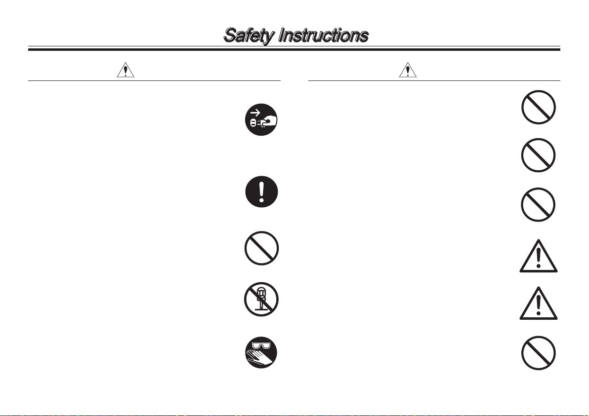
Power off
Safety Instructions
Prohibited
Prohibited
Prohibited
No modification
No dismantlement
Caution
Caution
Wear protectors
Prohibited
Prohibited
● Turn off the power.
Risk of electrical shock. Dismantling/
assembling the pump unit without turning off the power may cause an electrical
shock. Before engaging in any maintenance
or inspection work, be sure to turn off the
pump and related devices.
● Terminate operation.
On sensing any abnormality, stop operation
immediately and inspect/solve problems.
● For specified application only
The use of the pump in any application
other than those clearly specified may result
in injury or damage. Use the pump in a
specified condition.
● No dismantlement/modification
Do not dismantle/modify the pump. We are
not responsible for any accidents or damage
due to modification.
● Wear protective clothing.
Always wear protective clothing such as
safety goggles and protective gloves during
pipework or dismantlement.
WARNING
CAUTION
● Restriction on operator
The pump should be handled by a qualified
person with a full understanding.
● Specified power only
Do not apply any power other than the
specified one on the nameplate. Otherwise
damage or fire may result.
● Do not wet the pump.
If a liquid spills over electric parts or wires, a
fire or electrical shock may result. Install the
pump in a place free from liquid spillage.
● Ventilation
Poisoning may result when handling a toxic
or odorous liquid. Keep good ventilation in a
work area.
● Countermeasure against efflux
Take a protective measure against the accidental efflux caused by pump or pipe breakage.
● Damaged pumps.
Do not use any damaged pump. Using a
damaged pump may lead to an electric leak
or shock.
- 1 -
Page 4
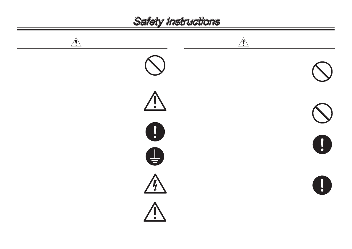
Prohibited
Safety Instructions
Caution
Prohibited
Electrical shock
Prohibited
Caution
Earthing
CAUTION CAUTION
● Do not place the pump close to water.
The pump is not dust-/water-proof construction. The use of the pump in a humid place
or a place where the pump can get wet may
result in electrical shock or short-circuit.
● Do not damage the power cable.
Risk of fire or electrical shock. Do not
scratch, modify, or pull the power cable.
The cable can also be damaged when it is
heated or loaded with a heavy thing.
● Do not cover the motor during operation.
Or heats builds up and fire or mechanical
failure may result.
● Earthing
Risk of electrical shock. Always earth the pump.
● Install an earth leakage breaker.
An electrical failure of the pump may adversely affect related devices. Purchase and
install an earth leakage breaker separately.
● Power cable is not replaceable.
Do not use any damaged power cable for
the prevention of a fire or electrical shock.
The cable is not replaceable, so that the
whole pump unit needs to be replaced when
the cable is damaged.
● Limited operating site and storage
Do not install or store the pump in the following places where...
1. Ambient temperature exceeds 40°C or
falls below 0°C.
2. Under a flammable/corrosive atmosphere.
● Do not drain a harmful chemical liquid
directly on the ground or the floor.
Use a container.
● Disposal of the used pump
Dispose of any used or damaged pump
in accordance with relevant regulations.
Consult a licensed industrial waste products
disposing company.
● Static electricity
When low electric conductivity liquids such
as ultra-pure water and fluor inactive liquid
(e.g. Fluorinert
TM
) are handled, the static
electricity may generate in the pump and
may cause static discharge. Take countermeasures to remove the static electricity.
- 2 -
Page 5
Outline
Before use, check the specification, limitation and hazardous
nature of the pump.
1. Unpacking & Inspection
On unpacking the product, check the following points. If
you find any problems, contact your nearest distributor.
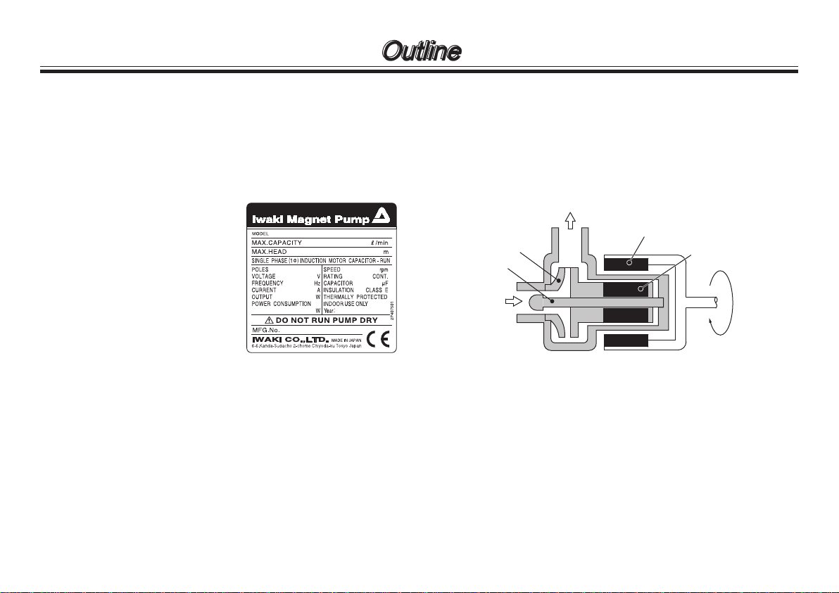
1. Check the information on the
nameplate such as model, discharge capacity, discharge head
and voltage to see that the product is delivered as per order.
2. Check for transit damage, deformation, and loose bolts.
2. Operating principle
The MD-F is a magnetic drive centrifugal pump.
The magnetic force of the motor drives the impeller magnet and rotates the impeller in the pump chamber, where a
liquid is transferred from the inlet to outlet.
Outlet
Drive magnet
Impeller
Spindle
Inlet
Driven magnet
- 3 -
Page 6
Outline
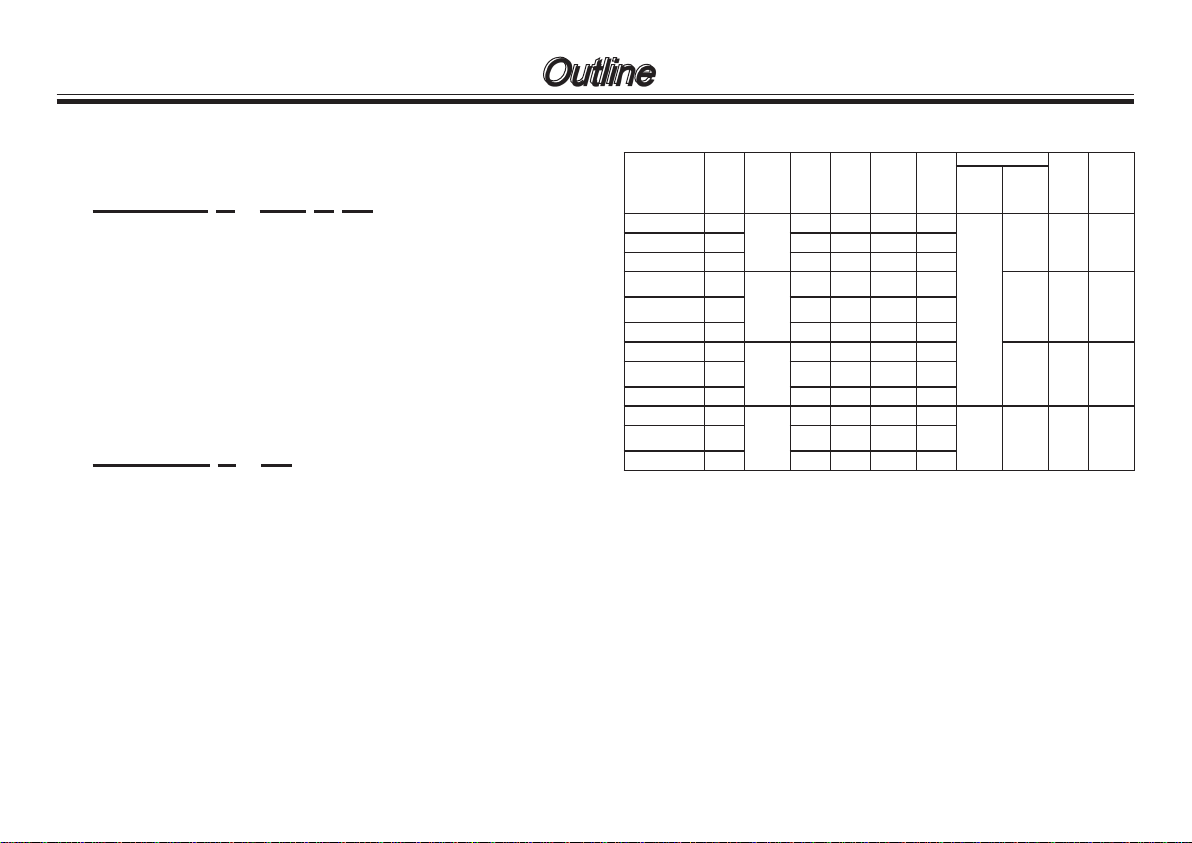
3. Specification & Identification code
Identification code
MD - 15F X - 220 N 01
a b c d e
a. Series model MD-15F/ -30F/ -55F/ -100F
b. Impeller type X, Y, Z
c. Power voltage 220: 220/240V (50Hz)
d. Motor type N: New type motor)
e. Special version No code: Standard
01-99: Special design
MD - 55F X - 01
a b c
a. Series model MD-55F/ -100F
b. Impeller type X, Y, Z
c. Special version No code: Standard
01-99: Special design
NOTE: Special design is different from standard in power cable
length, outlet direction, plug shape or terminal treatment.
Specification 50/60Hz
Max
Max
Impeller
Model
MD-15FX-220N X
MD-15FZ-220N Z -/10 -/3.1 -/2.5-6 -/1.9
MD-30FX-220N X
MD-30FY-220N Y 10/12 6/8
MD-30FZ-220N X -/11 -/7 -/5.5-7 -/1.9
MD-55FX X
MD-55FZ Z -/55 -/6.0 -/4.5-25 -/2.0
MD-100FX X
MD-100FZ Z -/115 -/8.5 -/6.5-55 -/1.9
type
Connec-
ow
tion
(L/min)
10/- 4.1/- 3-5/- 1.2/-
NPT 1/2
13/15 8/11
NPT 1/2
65/- 7.8/- 6.4-30/- 1.3/-
R1
125/- 10.5/- 7.5-65/- 1.2/-
R1
head
(m)
Norm
ow
(m-L/min)
5.5-8/
8.5-9.5
4.5-6.5/
6-8
3.8-30
/6.4-32
6-60/
8-70
Max SG
1.5/1.3
1.9/1.5
2.0/1.3
2.0/1.3
Power
(V)
220/240
(1ph)
220/240
(1ph)
220/380
(3ph)
400/440
(3ph)
Motor
Rated
output
(W)
10 1.8 0.06MD-15FY-220N Y 9/10 3/4 2-5/3-7 1.9/1.3
45 4.0 0.17
90 5.4 0.12MD-55FY Y 60/65 5.4/7.8
260/-
260/265
-/265
NOTE:
a. Performance data is based on pumping of clear water at
ambient temperature.
b. The maximum flow is obtained at zero discharge head, and
the maximum head is obtained at the maximum pressure.
c. The maximum viscosity is up to 30mPa•s (at SG 1.0).
d. Allowable liquid temperature is 0-80°C.
* Note that the liquid temperature is based on pumping clean
water and it changes with liquid property and operating conditions.
e. Non freezing
Mass
(kg)
8.5 0.17MD-100FY Y 115/135 8.5/11.5
Max
operating
pressure
(MPa)
- 4 -
Page 7
Outline
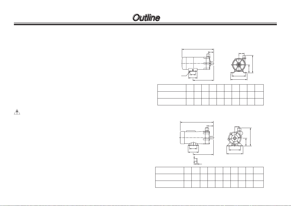
MD-15F-N
MD-30F-N
Model
W H Labc d e f G
95
120
120
130
186
231–405064681005560
34 28.5
38.5
123.5
15239
L
e
i
a
b
G
C
W
f
d
H
MD-55F
MD-100F
Model
W H Labc d e f G
120
156
155
174.3
270
320407064100
100
1106575
58.3 39.543198.5
19563
L
e
a
b
G
C
W
f
d
H
27
9
f. The maximum specific gravity is obtained at or near the
maximum flow. Note that the limitation varies with a duty
point, ambient or liquid viscosity.
g. Motor type
MD-15F/-30F/-55F: Single-phase capacitor-run induction
motor
MD-100F: Single-phase capacitor-run induction
motor or 3-phase induction motor
* The pump stops when the motor temperature becomes
extremely high due to ambient or liquid temperature rise or
overload operation. The pump resumes operation after temperature falls to a normal.
* For the IEC motor, consult your nearest distributor.
CAUTION
● If pump stops frequently, turn off power and check for
impeller damage or clogging. See “Troubleshooting” on
page 17.
● Do not dismantle the motor. Contact us for inspection.
4. Outer dimensions
● MD-15F-N/ -30F-N
● MD-55F/ -100F
- 5 -
Page 8

Outline
15
10
5
0 2 4 6 8 10 12
15
10
5
0 2 4 6 8 10 12
50Hz 60Hz
MD.30FX
MD.30FX
MD.30FY
MD.15FY
MD.15FZ
MD.30FZ
MD.30FY
MD.15FX
MD.15FY
15
10
5
0 25 50 75 100 125 150
15
10
5
0 25 50 75 100 125 150
50Hz
60Hz
MD.100FX
MD.100FY
MD.55FX
MD.55FY
MD.100FY
MD.100FZ
MD.55FY
MD.55FZ
5. Performance curves
● MD-15F-N/ -30F-N
Flow rate Flow rate
* Performance data is based on pumping of clear water at ambi-
ent temperature.
● MD-55F/ -100F
Head Head
* Performance data is based on pumping of clear water at ambi-
ent temperature.
Flow rate Flow rate
6. Overview & Label
Pump unit (Liquid feeding unit)
Not capable of self-priming. Always prime
the pump before operation.
Inlet
- 6 -
Outlet
Specification label
Use the pump according to the specifications on the label.
Motor (drive unit)
Do not wet the
pump and motor
units.
Base
Fix the pump securely.
Page 9

7. Part names & Structure
101
2 8 3 5
15
6
1
9
No. Part names Q'ty Materials Remarks
1 Front casing 1 CFRETFE
2 Bearing 2 SiC
3 Rear casing 1 CFRETFE
5 O ring 1 FKM
6 Impeller 1 CFRETFE
8 Spindle 1 SiC
9 Thrust ring 2 SiC
15 Machine screw 6 Stainless steel
101 Motor 1
Outline
- 7 -
Page 10

Installation
1. Before Installation
Read through this instruction manual before use. Carry
out installation work with a full understanding.
WARNING
● Risk of electrical shock. Dismantling/assembling the
pump unit without turning off the power may cause
an electrical shock. Before engaging in any maintenance or inspection work, be sure to turn off the
pump and related devices.
● Electrical work or wiring must be carried out by a
qualified person according to local laws or regulations.
CAUTION
● Do not drop the pump.
● A strong magnet is inside the pump. Do not bring a
watch or floppy disk which may be adversely affected by a magnetic force.
● Do not run pump dry. If the pump runs without a liquid, friction heat damages the pump.
● Dropping or subjecting the pump to
strong impact, failure may result.
Handle the pump with care.
● The pump is not capable of self-
priming. Always prime the pump
before operation.
● Allowable liquid temperature range
is 0-80°C. Non-freezing. Note
the range may change with liquid
property.
- 8 -
Page 11

Installation
● A strong magnet is inside the
pump. Do not use the pump with
any liquid which contains metals
such as iron and nickel.
CAUTION
Do not install or store the pump in
the following places where...
1. Ambient temperature exceeds
40°C or falls below 0°C.
2. In a dusty/humid place or cor-
rosive atmosphere.
3. Under direct sunlight or wind &
rain.
● Observe the maximum ambient
humidity of 90%. The motor is not
water-/dust-proof. Do not wet the
motor, or it may fail.
● Banned solutions
• Halogenated hydrocarbons such
as trichloroethylene and carbon
tetrachloride
• Ether and low-grade ester
• Slurry (Never use slurry, which
wears out the pump bearings.)
● Do not place dangerous or am-
mable goods near the pump for
your safety.
● An electrical failure of the pump
may adversely affect related
devices. Purchase and install an
earth leakage breaker separately.
● Non-condensing. Do not wet the
motor.
● Do not dismantle/modify the pump.
We are not responsible for any
accidents or damage due to modification.
- 9 -
Page 12

Installation
● Do not use any damaged pump.
Using a damaged pump may lead
to an electric leak or shock.
● Do not get the motor wet. The
pump is not dust-/water-proof or
rust-proof construction.
● Risk of fire or electrical shock. Do
not scratch, modify, twist or pull the
power cable. The cable can also
be damaged when it is heated or
loaded with a heavy thing. Stop
operation and contact us if the
power cable is damaged.
● Risk of burning. Do not touch the
motor. Motor surface temperature
rises high during operation.
● Noise level during operation is as below.
Model Noise level Model Noise level
MD-15FX
55dB
MD-15FZ MD-55FZ
MD-30FX
60dB
MD-30FZ MD-100FX
*Noise level is measured in A scale at a distance of 1m.
MD-55FX
55dBMD-15FY MD-55F Y
MD-100FX
75dBMD-30F Y MD-100FY
- 10 -
Page 13

Installation
30cm
or
more
2. Installation/ Piping/ Electrical wiring
Stop working upon sensing danger or abnormality in
work.
CAUTION
● Wear protective clothing.
Always wear protective clothing such as safety goggles and protective gloves during pipework or dismantlement.
● A qualied operator only
The pump must be handled or operated by a quali-
ed person with a full understanding of the pump.
Any person who is not familiar with this product
should not take part in operation or management.
2.1 Installation
1. Installation location
Select a convenient place for
maintenance and inspection.
Observe the allowable room temperature of 0-40°C and ambient
humidity of 90%RH.
2. Mounting position
This pump is not capable of selfpriming. Flooded suction application is ideal. The pump should be
installed 30cm lower than the suction liquid level, or bearing may be
worn soon by entrained air.
3. Outlet direction
Always direct the outlet upward or
entrained air can not be expelled.
Do not mount the pump vertically.
4. Pump fixation
Secure the pump by fixing the
base. Do not install the pump
vertically.
- 11 -
Direct the outlet upward
Page 14

Installation
2.2 Piping
1. In order to minimize the piping resistance, have piping shortest with the minimum bends. For the prevention of cavitation,
have the suction piping bore wide as much as possible.
2. Use a corrosion-/pressure-resistant vinyl tube, otherwise
the suction hose can be crushed by the suction force (especially for hot liquid). A braided tube or Teflon tube is recommended.
3. For the MD-55F & -100F, be sure
to remove a cushion from the
outlet before pipework. Be careful
not to damage the wet ends, especially SiC parts.
4. Select a suitable tube bore for
secure connection.
5. Install valves on both discharge
and suction lines.
• Suction-side valve:
For easy pump removal and
maintenance.
• Discharge-side valve:
For adjustment of the flow rate
and discharge head.
Dischargeside valve
Suction-side valve
- 12 -
Page 15

Installation
Brown
Blue
Thermal protector
Power source
Yellow/Green
Auxiliary coil
Capacitor
Main coil
Thermal protector
Thermal
protector
Power
source
Rotor
(220V)
Red
Gray
W2
U1
White
Blue
U2
V1
Black
Yellow
V2
W1
2.3 Electrical wiring
Electrical wiring must be done by qualified person who has a
full knowledge of safety. We are not responsible for the injury
or damage accident due to nonobservance of this warning.
Contact us or your nearest distributor for wiring as necessary.
■
Before wiring
1. Confirm that the power is disconnected before work.
2. Wiring work should be done in accordance with electric
work requirements. Use the recommended wiring accessories and follow electrical installation requirements.
3. Apply the specified power voltage. See the spec label.
4. The pump doesn't have the ON-OFF switch. The pump
starts as the power cable is plugged in.
5. Earth the pump by an earthing wire.
6. When a leakage breaker is used.
Always solve the root cause when a leakage breaker operates. Replace the fuse and resume operation. Be sure to
unplug the pump before investigation.
■
Connection diagram
● Single-phase capacitor-run induction motor
(MD-15/-30/-50/-100F types)
● 220/380V 3-phase motor
(MD-100F type)
- 13 -
Page 16

● 400/440V 3-phase motor
Thermal protector
Thermal
protector
Power
source
(380V)
Red
Gray
W2
U1
White
Blue
U2
V1
Black
Yellow
V2
W1
Thermal protector
Thermal
protector
Power
source
(MD-100F type)
Installation
■
Rated current & Starting current (50/60Hz)
Model
MD-15FX-220N 0.18 / - - - 0.3 / 0.29 - MD-15FY-220N 0.18 / 0.2 - - 0.4 / 0.4 - -
MD-15FZ-220N - / 0.2 - - 0.4 / 0.4 - MD-30FX-220N 0.41 / 0.49 - - 0.4 / 0.4 - MD-30FY-220N 0.37 / 0.37 - - 1.2 / 1.25 - MD-30FZ-220N - / 0.32 - - 1.2 / 1.25 - -
MD-55FX 1.0 / - - - 1.2 / 1.25 - MD-55FY 1.0 / 0.9 - - 1.1 / 1.0 - MD-55FZ - / 0.9 - - 1.1 / 1.0 - -
MD-100FX 1.93 / - 1.18-0.69 / - 0.62-0.6 / - 3.8- 4.3 / - 3.8-2.2 / - 1.9-2.2 / -
MD-100FY
MD-100FZ
220/240V
Single phase
1.93-1.93 /
1.85-1.83
- /
1.85-1.83
Rated current Starting current
220/380V
3 phases
1.18 -0.69 /
1.17-0.67
- / 1.17-0.67 - / 0.6-0.58 - / 3.6-4.0 - / 3.7-2.1 - / 1.85-2.1
400/440V
3 phases
0.62-0.6 /
0.6-0. 5 8
220/240V
Single phase
3.8-4.3 /
3.6-4.0
220/380V
3 phases
3.8-2.2 /
3.7-2.1
400/440V
3 phases
1.9-2.2 /
1.85-2.1
- 14 -
Page 17

1. Before operation
CAUTION
● Before operation, check that the pump is firmly
installed in piping via the inlet and outlet and the
pump is securely fixed.
● Do not run pump dry. If the pump runs without a liquid, the pump is damaged by friction heat.
● Do not run the pump with a discharge/suction valve
closed.
● Do not open the discharge valve or suction valve at
once, otherwise the magnetic coupling may disconnect (In this case turn off the power.).
Operation
■
Operation
After installation, piping and wiring work are completed, operate the pump in accordance with the following procedures.
No. Procedure Points to be checked
1 Check piping, wir-
2 Open or close a
3 Prime the pump
4 Supply power to the
5 Adjust discharge
ing and voltage.
valve.
chamber.
pump.
capacity & discharge head to
specified level.
• See "2.2 Piping" and "2.3
Electrical wiring" sections.
• Check the spec label to see if the
power supply voltage is correct.
• Fully open a suction-side valve.
• Fully close a discharge-side valve.
• Prime the pump with liquid (In suc-
tion lift application).
• Check the item 1, 2 and 3. Then
turn on power and start the pump.
Open a discharge-side valve gradually till the flow and head reach
a specified level. Do not open or
close the valve at once.
Note: Do not keep the discharge-
side valve closed more than 1
minute.
Note: Check that the pump trans-
fers a liquid without trouble.
If there is a problem, turn
off the power immediately
and solve the cause. See
"Troubleshooting" section.
- 15 -
Page 18

Operation
No. Procedure Points to be checked
6 Points to be
checked during
operation
■
Shutdown
No. Procedure Description
1 Close a discharge-
side valve.
2 Turn off power. Check if the motor stops rotating
■
Before a long period of storage
Remove the liquid from the pump before it is stored for a long
time. In addition, run the pump with clean water for 5 minutes
every 3 months to prevent the motor bearing from being stuck.
• Do not allow foreign matters to
enter the pump. Foreign matters
may cause impeller to be locked,
hindering liquid circulation. In this
case turn off power immediately
(Contact us).
• Turn off power when the leakage
breaker operates. Investigate the
root cause on the Trouble shooting
section of page 17.
Close the discharge-side valve
gradually. Do not use the solenoid
valve.
smoothly as turning off power. If
it is not smooth, check the motor.
Contact us for detail.
■
Drainage
WARNING
● Turn off power before work.
● Always wear protective clothing such as safety gog-
gles and protective gloves during pipework or dismantlement.
CAUTION
● Do not get wet with chemical when removing the
hose. Do not wet the motor or electric parts.
● Do not drain a harmful chemical liquid directly on
the ground or the floor. Always use a container.
■
Procedure
1. Turn off power. Make sure no one turns on the power while
working on the pump.
2. Close the discharge- and suction-side valves fully.
3. Place a container under the pump and loosen the hose
clamp. Pull out hoses from the inlet and outlet. Be careful
not to get wet with chemicals.
4. Unfix and take out the pump.
5. Drain residual chemicals through the inlet. Do not drain a
harmful chemical liquid directly on the ground or the floor.
Use a container.
- 16 -
Page 19

Maintenance
1. Trouble shooting
Handling of the pump, maintenance and inspection should
be carried out within this instruction manual. Do not handle the pump beyond the descriptions in this manual.
We are not responsible for any personal injury or property
damage due to nonobservance of this warning. Contact us
or your nearest distributor as necessary.
Phenomenon
Causes
Wrong wiring Inspect wiring. Rewire as
Motor failure
Air is trapped.
Air suction from the inlet
Dry running
Too high SG or viscosity
Impeller magnet hits the
rear casing
Impeller is damaged.
Foreign matters on the
impeller.
O ring is damaged
Pump head mounting
screws are loose.
The pump does not run.
Poor discharge head
Overcurrent
Noise and vibration problem
Leakage
necessary.
Contact us.
Eliminate air.
Check suction piping.
Prime the pump before
operation.
Replace with suitable pump.
Contact us.
Contact us.
Contact us.
Contact us
Tighten the mounting
screws.
Measure
2. Maintenance & Inspection
WARNING
● Always wear protective clothing such as safety goggles and protective gloves during pipework or dismantlement.
CAUTION
● Do not get wet with chemical when removing the
hose. Do not wet the motor or electric parts.
● Do not drain a harmful chemical liquid directly on
the ground or the floor. Always use a container.
■
Retightening
After a long period of operation or storage, the pump head
mounting screws may be loose. Tighten the mounting screws
as necessary, but then do not deform the plastic pump head.
■
Daily inspection
Always check for abnormality in vibration, noise, current value,
and discharge capacity. Stop operation on sensing any abnormality. And solve problems on the trouble shooting section.
- 17 -
Page 20

Maintenance
15
1
5
3
6
11
101
■
Wear parts
● Replace wear parts before the end of estimated life.
● The estimated life is calculated based on the continuous
operation with ambient temperature clean water and changes with operating conditions.
● We are note responsible for damage due to use of slurry.
● Replace O ring with new one every time dismantling the
pump despite of the estimated life.
No. Parts Estimated life
1 Front casing
3 Rear casing
5 O ring
6 Impeller
101 Motor
10,000hours
- 18 -
Page 21

Australia IWAKI Pumps Australia Pty. Ltd.
Austria IWAKI EUROPE GmbH
Belgium IWAKI Belgium n.v.
China IWAKI Pumps (Shanghai) Co., L td.
China
China
China
IWAKI Pumps (Guangdong) Co., Ltd.
GFTZ IWAKI Engineering & Trading (Guangzhou)
GFTZ IWAKI Engineering & T rading (Beijing )
Denmark IWAKI Nordic A/S
Finland IWAKI Suomi Oy
France IWAKI France S.A.
Germany IWAKI EUROPE GmbH
Holland
IWAKI Europe GmbH, Netherlands Branch
Hong Kong IWAKI Pumps Co., Ltd.
Indonesia
IWAKI Singapore (Indonesia Branch)
IWAKI CO.,LTD. 6-6 Kanda-Sudacho 2-chome Chiyoda-ku Tokyo 101-8558 Japan
TEL : (61)2 9899 2411 FAX : 2 9899 2421
TEL : (49)2154 92540 FAX : 2154 9254 48
TEL : (32)1367 0200 FAX : 1367 2030
TEL : (86)21 6272 7502 FAX : 21 6272 6929
TEL : (86)750 3866228 FAX : 750 3866278
TEL : (86)20 8435 0603 FAX : 20 8435 9181
TEL : (86)10 6442 771 3 FAX : 10 6442 7712
TEL : (45)48 24 2345 FAX : 48 24 2346
TEL : (358)9 27 45810 FAX : 9 274271 5
TEL : (33)1 69 63 33 70 FAX : 1 64 49 92 73
TEL : (49)2154 9254 0 FAX : 2154 9254 48
TEL : (31)547 293 160 FAX : 547 292 332
TEL : (852)2 607 1 168 FAX : 2 607 1000
TEL : (62)21 690 6606 FAX : 21 690 6612
TEL:(81)3 3254 2935 FAX:3 3252 8892(http://www.iwakipumps.jp)
Italy
Korea IWAKI Korea Co.,Ltd.
Malaysia IWAKIm Sdn. Bhd.
Norway IWAKI Norge AS
Singapore IWAKI Singapore Pte. Ltd.
Spain
Sweden IWAKI Sverige AB
Switzerland IP Service SA
Taiwan IWAKI Pumps Taiwan Co., Ltd.
Taiwan
Thailand IWAKI (Thailand) Co.,Ltd.
U.K. IWAKI Pumps (UK) LTD.
U.S.A. IWAKI AMERICA Inc.
Vietnam IWAKI pumps Vietnam Co.,Ltd.
IWAKI Europe GmbH, Italy Branch
TEL : (39)0444 3711 15 FAX : 0444 335350
TEL : (82)2 2630 4800 FAX : 2 2630 4801
TEL : (60)3 7803 8807 FAX : 3 7803 4800
TEL : (47)23 38 49 00 FAX : 23 38 49 01
TEL : (65)6316 2028 FAX : 6316 3221
IWAKI Europe GmbH, Spain Branch
TEL : (34)93 37 70 198 FAX : 93 47 40 991
TEL : (46)8 511 72900 FAX : 8 511 72922
TEL : (41)26 674 9300 FAX : 26 674 9302
TEL : (886)2 8227 6900
IWAKI Pumps Taiwan (Hsin-chu) Co., Ltd. TEL : (886)3 573 5797 FAX : (886)3 573 5798
TEL : (66)2 322 247 1 FAX : 2 322 2477
TEL : (44)1743 231363 FAX : 1 743 366507
TEL : (1)508 429 1440 FAX : 508 429 1386
TEL : (84)613 933456 FAX : 613 933399
( )Country codes
FAX : 2 8227 6818
T865 '13/10
 Loading...