

Page 1
© 2008 IWAKI CO.,LTD.
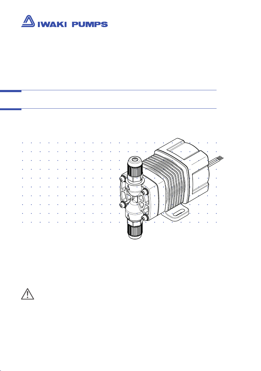
Iwaki Hi-Resolution Pump
HRP (Standard)
Instruction manual
Thank you for choosing our product.
Please read through this instruction manual before use.
This instruction manual describes important precautions and
instructions for the product. Always keep it on hand for quick
reference.
Page 2
2
HRP
Instruction manual
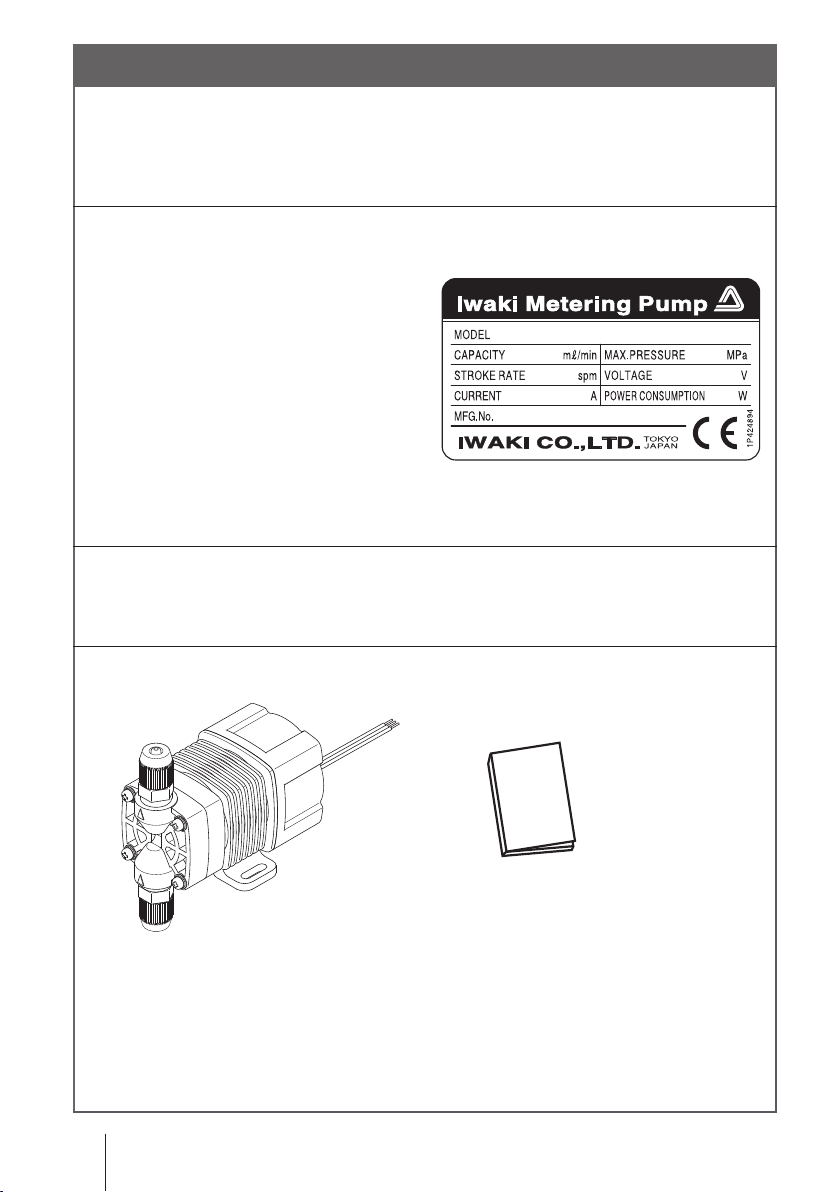
Order conrmation
After unpacking, check the following points. Contact us or your nearest
dealer if the delivery is imperfect.
a. Check if the delivery is as per order.
Check the nameplate to see if the dis-
charge capacity, discharge pressure
and voltage are as per order.
b. Check for transit damage.
c. Check for loose screws.
Delivery should include...
HRP with a special power cable
Order conrmation
Instruction manual
Page 3

Contents
Order conrmation ............................................................................................. 2
Safety instructions .......................................................................5
WARNING .......................................................................................................... 6
CAUTION ........................................................................................................... 7
Precautions for use ......................................................................................... 9
Outline ......................................................................................... 11
Introduction .....................................................................................................11
Pump structure & Operating principle .........................................................11
Features .......................................................................................................12
Operational function ....................................................................................12
Part names.......................................................................................................13
Identication codes ........................................................................................14
Installation .................................................................................. 15
Pump mounting ...............................................................................................15
Pipework ..........................................................................................................16
Tube connection ..........................................................................................16
Check valve mounting .................................................................................17
AVC check valve with an air vent (Option) ...................................................19
Wiring .............................................................................................................. 20
Power & External signal cables .................................................................. 20
Operation .....................................................................................24
Before operation ............................................................................................ 24
Points to be checked ...................................................................................24
Retightening of pump head unit xing screws .............................................24
Degassing ................................................................................................... 25
Operation .................................................................................................... 27
Contents
3
Page 4

4
Operation of the Pulse control type ....................................................... 27
Operation of the 4-20mA control type ................................................... 27
Operation of the 1-5V control type ........................................................ 28
Operation of the STOP control type ...................................................... 28
Flow rate adjustment .................................................................................. 29
Relation between the ow rate & stroke rate ........................................ 29
Maintenance ................................................................................30
Troubleshooting ............................................................................................. 30
Inspection ........................................................................................................31
Daily inspection ...........................................................................................31
Periodic inspection ..................................................................................... 32
Before a long period of stoppage ............................................................... 32
Wear part replacement .................................................................................. 33
Wear part list ............................................................................................... 33
Before replacement .................................................................................... 34
Pump head/Diaphragm replacement .......................................................... 34
Maintenance (AVC check valve) ....................................................................37
Exploded view (AVC check valve) ...............................................................37
Wear parts list (AVC check valve) .............................................................. 38
Wear parts replacement (AVC check valve) ............................................... 38
Exploded view ................................................................................................ 42
Pump head, Drive unit & Control unit ..........................................................42
Specication/Outer dimension .................................................................... 43
Specication ............................................................................................... 43
Pump & Drive units ................................................................................ 43
Control unit ............................................................................................ 43
Power cable ........................................................................................... 43
Option ......................................................................................................... 44
Check valve with an air vent .................................................................. 44
Check valve ........................................................................................... 44
Outer dimension ......................................................................................... 45
HRP-54V ............................................................................................... 45
HRP-54H ............................................................................................... 45
Contents
Page 5
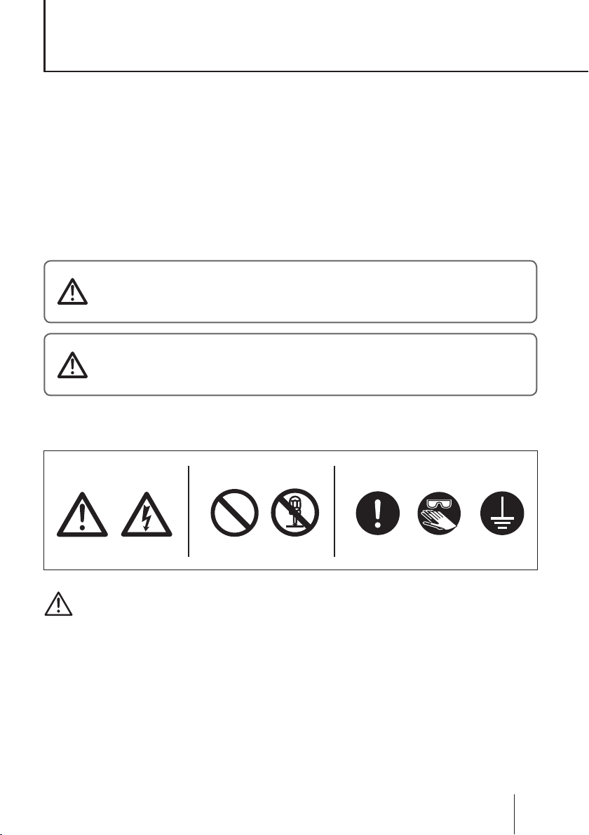
Prohibition
Electrical
shock
Caution
Do not remodel
Requirement
Wear
protectors
Earthing
Safety instructions
Read through this section before use. This section describes
important information for you to prevent personal injury or
property damage.
■
Pictorial indication
In this instruction manual, the estimated risk of degree caused by incorrect use
is ranked with the following pictorial indications. First, fully understand informa-
tion on the pictorial indications.
I
WARNING
CAUTION
Pictorial indication accompanies each precaution, suggesting "Caution", "Pro-
hibition" and "Requirement".
ndicates mishandling could lead to a fatal or
serious injury accident.
I
ndicates mishandling could lead to personal or
property damage.
Technology related to the use of goods in this instruction manual falls in the
category of technology contained in the Foreign Exchange Order Attachment,
which includes complementary export control of technology. Please be remind-
ed that export license, which is issued by the Ministry of Economy, Trade, and
Industry could be required, when this is exported or provided to someone even
in Japan.
Caution marks Prohibition mark Requirement mark
For exportation
Safety instructions
5
Page 6

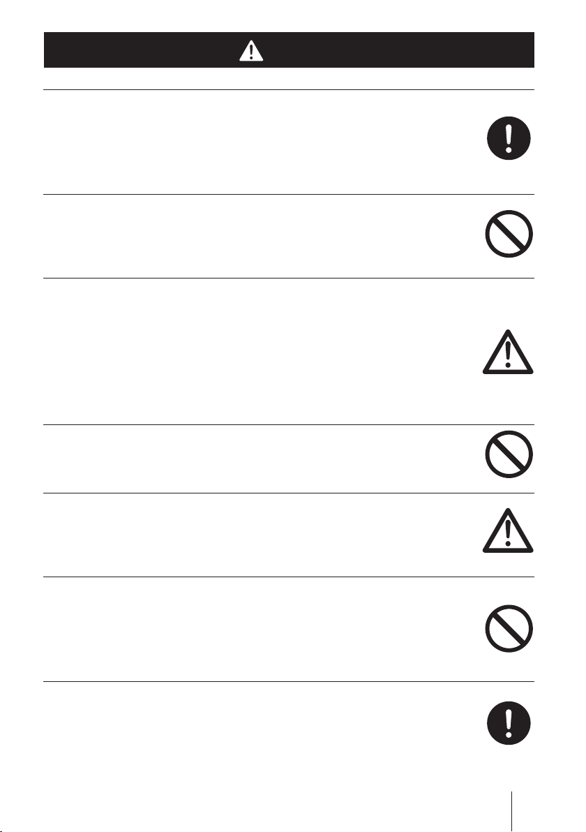
WARNING
Prohibition
Requirement
Do not remodel
Wear
protectors
Electrical
shock
Prohibition
Prohibition
Turn off power before work
Risk of electrical shock. Be sure to turn off power to stop the pump
and related devices before work.
Stop the operation
On sensing any abnormality or dangerous sign, suspend operation
immediately and inspect/solve problems.
Do not use the pump in anything other than a specied purpose
The use of the pump in any purpose other than those clearly speci-
ed may result in failure or injury. Use this product in a specied
condition.
Do not modify the pump
Remodelling the pump carries a high degree of risk. We are not
responsible for any failure or injury results from remodelling.
Wear protective clothing
Always wear protective clothing such as an eye protection, chemi-
cal resistant gloves, a mask and a work cap during dismantlement,
assembly or maintenance work.
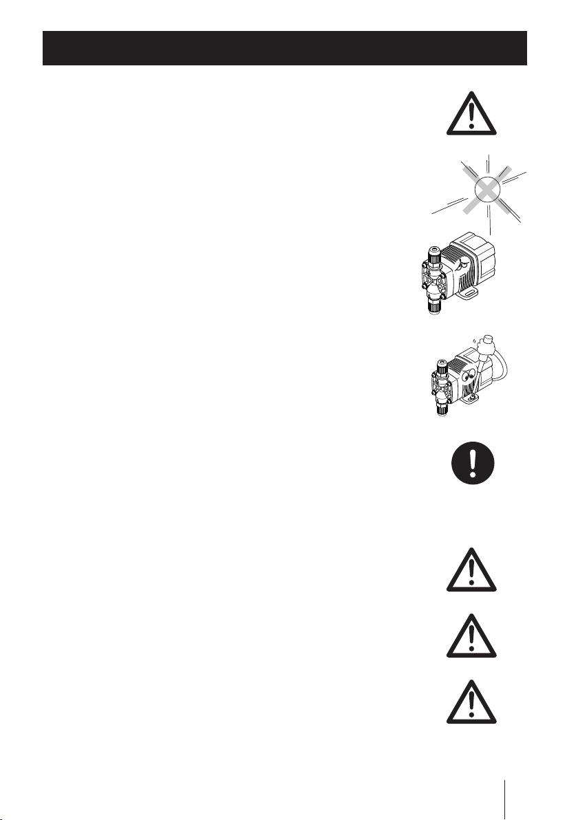
Do not damage the power cable
Do not pull or knot the power cable or place a heavy stuff on it.
Damage to the power cable could lead to a re or electrical shock.
Do not use the pump in a ammable atmosphere
Do not place dangerous or ammable goods near the pump for your
safety.
WARNING
6
Page 7
CAUTION
Prohibition
Requirement
Prohibition
Prohibition
Caution
Caution
Requirement
A qualied operator only
The pump must be handled or operated by a qualied person with a
full understanding of the pump. Any person who is not familiar with
this product should not take part in operation or management.
Use a specied power only
Do not apply any power other than the one specied on the nameplate.
Otherwise, failure or re may result.
Do not run pump dry
Do not run pump dry for more than 30 minutes (even when the
pump runs for degassing). Otherwise, the pump head unit xing
screws may loosen, or the pump head unit and valve case may
deform by friction heat, and consequently leakage results. Optimise
your system in order for the pump not to run dry.
Do not wet electric parts or wiring
Risk of re or electrical shock. Install the pump free from liquid spill.
Ventilation
Poisoning may result when handling a toxic or odorous liquid. Keep
good ventilation in your operating site.
Do not install or store the pump in the following places where...
• Under a ammable atmosphere or in a dusty/humid place.
• Ambient temperature is beyond 0-40 degrees Celsius.
• Under direct sunlight or wind & rain.
Countermeasure against efux
Take a protective measurement against an accidental chemical
overow results from pump or piping breakage.
CAUTION
7
Page 8
8
Observe the correct polarity
Prohibition
Requirement
Requirement
Caution
Prohibition
Caution
Otherwise the pump may fail.
Do not use the pump in a water place
The pump is not totally waterproof. The use of the pump in water or
high humidity could lead to electrical shock or short circuit.
Wear part replacement
Follow instructions in this manual for wear part replacement. Do not
dismantle the pump beyond the extent of the instructions.
Do no use a damaged pump
Using a damaged pump could lead to an electric leak or shock.
Disposal of the used pump
Dispose of any used or damaged pump in accordance with relevant
regulations. Consult a licensed industrial waste products disposing
company.
Keep the pump head unit securely xed
Liquid may leak if pump head unit xing screws are loose. Tighten
the screws diagonally and evenly before initial operation. Also, peri-
odically tighten the screws for the prevention of leakage.
Tightening torque: 0.7 N•m
CAUTION
Page 9
Precautions for use
Caution
Caution
Caution
Caution
Requirement
• Electrical work should be performed by a qualied opera-
tor. Otherwise, personal or property damage accident may
result.
• Do not install the pump in the following places where...
–Under a ammable atmosphere or in a dusty/humid place.
–Under direct sunlight or wind & rain.
– Ambient temperature is beyond 0-40 degrees Celsius.
Protect the pump with a cover when installing it out of
doors.
• Select a level location where is free from vibration and
liquid can't stay. Fix the pump with M4 screws so as not to
vibrate. If the pump is installed at a tilt, the ow may reduce.
• When two or more pumps are installed, the pump opera-
tion interacts each other and vibration becomes signicant,
resulting in poor performance or failure of internal electri-
cal devices. Select an installation location where tolerates
vibration to enough degree.
• Keep a wide maintenance space around the pump.
• Install the pump as close to a supply tank.
• Install the pump in a cool and dark place when handling
liquids that readily generate gas bubbles such as sodium
hypochlorite or hydrazine solution. Flooded suction mount-
ing is strongly recommended when using the pump with a
supply tank.
Precautions for use
9
Page 10
10
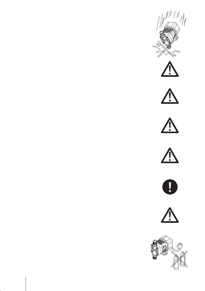
• Be careful not to drop the pump onto the oor. A strong
Caution
Caution
Caution
Caution
Caution
Requirement
Benzine
Thinner
impact may reduce pump performance. Do not use a pump
which has once damaged. Otherwise an electrical leak or
shock may result.
• The pump is a light water-/dust-proof structure of IP65, but
is not totally waterproof. Do not have the pump wet with the
liquid handled or rainwater.
• Never wet the pump head, control unit and drive unit. Oth-
erwise, Failure or an accident may result. Immediately wipe
off liquid if the pump has got wet.
• Do not close the discharge line during operation. Other-
wise, liquid may leak or tubing may break.
• Do not remove the control unit. Otherwise, an electrical
circuit or the drive unit may fail.
• Release the pressure from the discharge line before disman-
tling the pump or removing tubing. Otherwise, chemical liquid
gushes out.
• Be careful not to come in contact with residual liquid.
• Do not clean the pump or nameplate with a solvent such
as benzene and thinner. This may discolour the pump or
erase printing. Use a dry cloth or a wet cloth with water or
neutral detergent.
Precautions for use
Page 11
Outline
IN
OUT
The information such as characteristics, features and part
names are described in this section.
Introduction
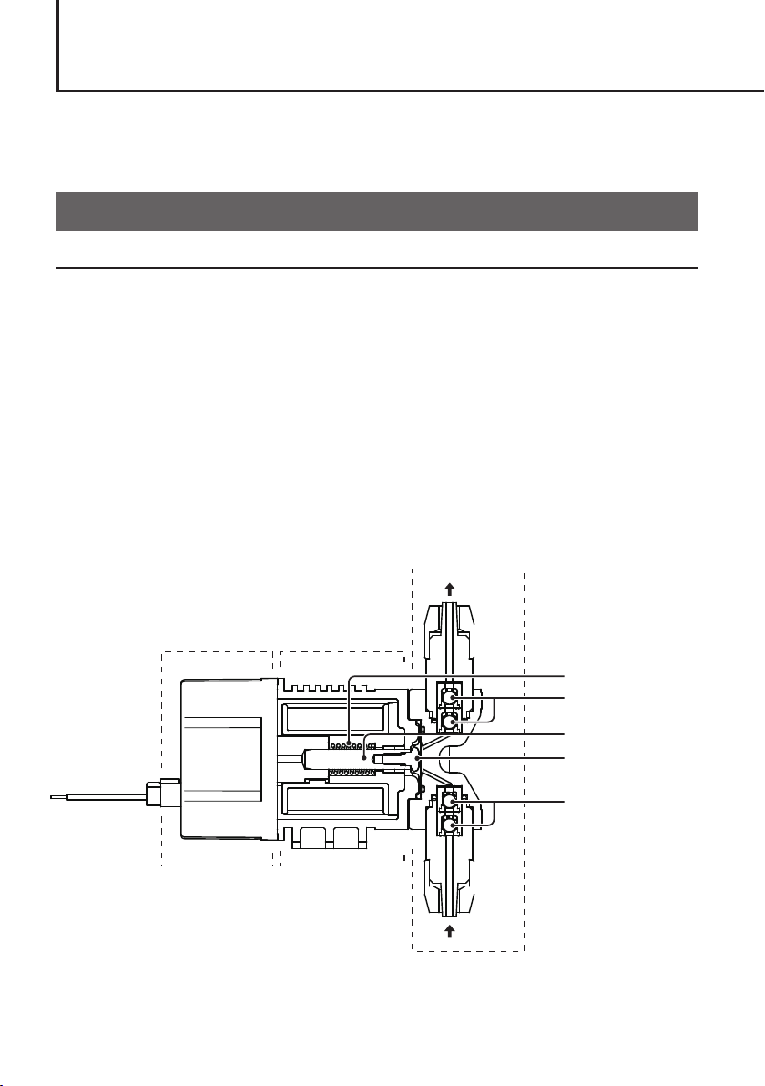
Pump structure & Operating principle
The HRP series is a diaphragm metering pump which consists of a pump
head, drive unit and control unit. A diaphragm is directly driven by electromag-
netic force.
Principle of operation
The pulse signal controls the electromagnetic force in order to make recip-
rocating motion that is assisted by spring force. The reciprocating motion is
transferred to a diaphragm through a plunger and then volumetric change oc-
curs in the pump head. This action transfers liquid along with pump head valve
action.
Pump head
Control unit
Drive unit
Spring
Pump head valve
(Discharge side)
Plunger
Diaphragm
Pump head valve
(Suction side)
Introduction
11
Page 12

12
Features
12/24VDC power voltage
The HRP series powered by 12VDC or 24VDC offers the best t to the built-in
application.
High resolution
Digitally-controlled spm range is 0-720spm. The minimum ow of 0.055ml per
shot offers a constant imperceptible injection.
* The operation speed of the stop control type is always xed to 720spm and is not vari-
able.
Waterproof and dustproof structure
The sealed drive unit and control unit assure the water-/dust-proof of IP65.
* This pump is not completely water resistant. Do not expose it to wind and rain.
Operational function
The HRP pump is controlled by the external signal and falls into the following
types.
Pulse control type (see page 27)
The input of the pulse signal controls the pump operation (stroke rate).
The pump makes one shot per pulse synchronously.
*The signal input is required to make operation after power activation for this type.
* The pump can not run over 720spm even if the external signal is entered to run the
pump beyond the maximum spm.
4-20mA control type (see page 27)
The input of 4-20mA proportionally controls the pump operation (stroke rate).
*The signal input is required to make operation after power activation for this type.
1-5V control type (see page 28)
The input of 1-5V proportionally controls the pump operation (stroke rate).
*The signal input is required to make operation after power activation for this type.
Stop control type (see page 28)
The input of the stop signal suspends the pump operation.
* This type of pump starts to run at 720spm upon power activation.
Introduction
Page 13
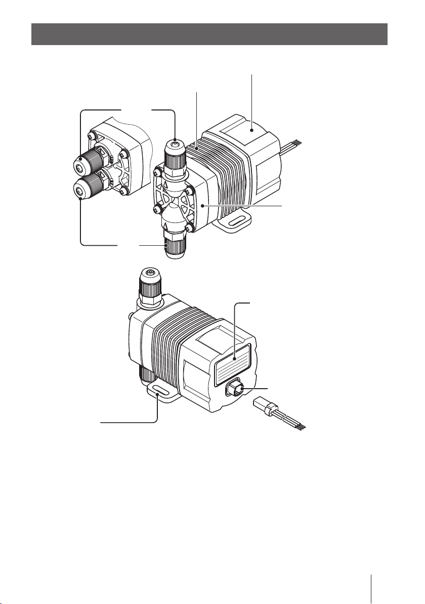
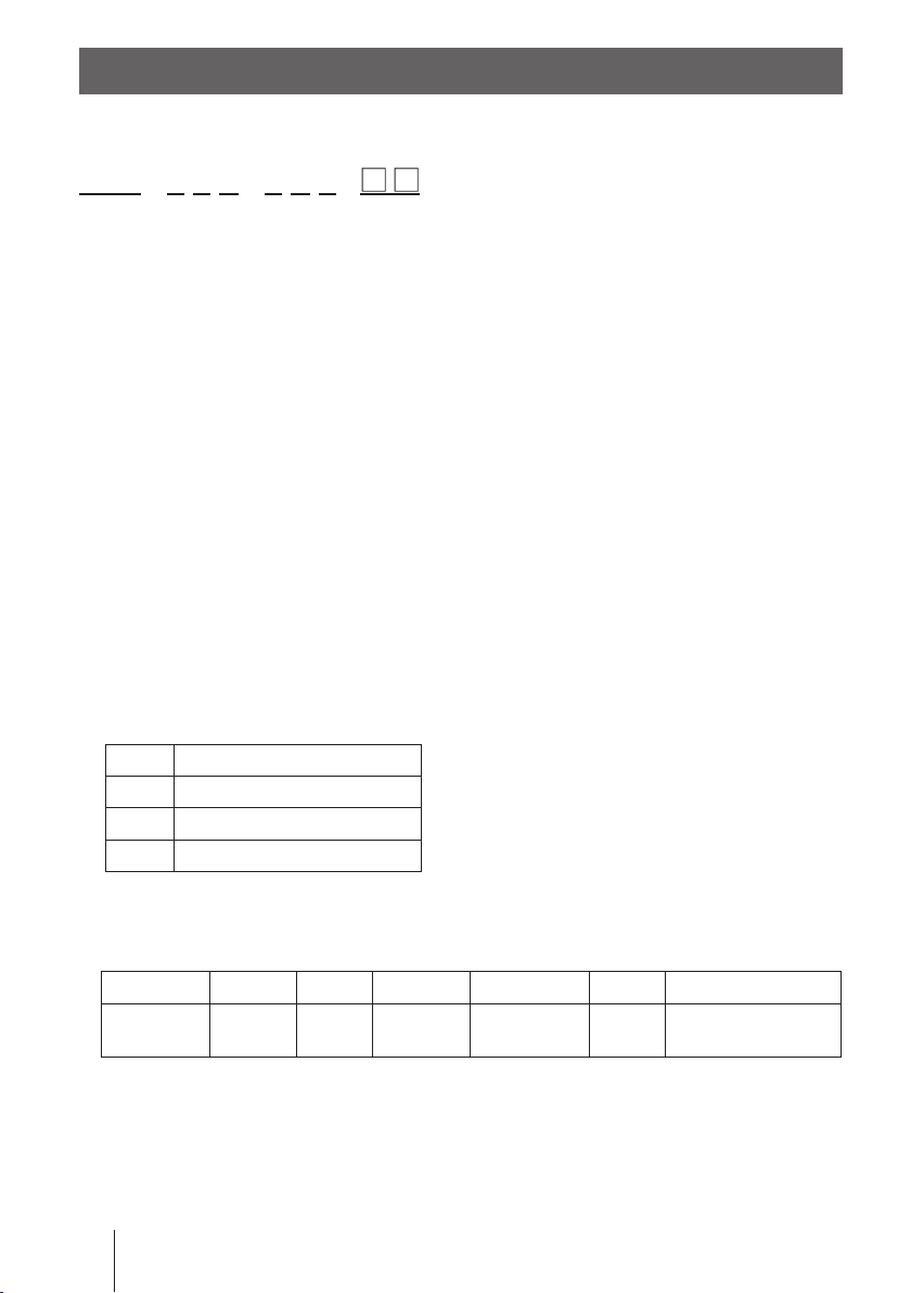
Part names
Control unit
Drive unit
Outlet
H type
Inlet
Base
Always fix with screws.
Pump head unit
(Pump head)
V type
Nameplate
Describes the pump
specification.
Power cable terminal
Part names
13
Page 14
14
Identication codes
The model code represents the following information.
HRP - 5 4 V - 1 P 1 -
a b c d e f g H
a. Series name
HRP: High resolution pulse pump
b. Drive unit (Average power consumption)
5: 5.6W
c. Discharge capacity
4: 38ml/min
d. Pump head
V: Vertically oriented H: Horizontally oriented
e. Power voltage
1: 12VDC
2: 24VDC
f. Control method
P: Pulse control A: 4-20mA control V: 1-5V control S: Stop control
g. Connection bore
No. Tube connection bore
1 ø3×ø6mm
2 ø4×ø6mm
3 ø1/8"×ø1/4"
H. Special version
Wet end materials
Pump head Valve O ring Valve seat Valve spring Gasket Diaphragm
PVDF
* Valve springs are equipped to the H type only.
Material code
PVDF : Polyvinylidene diuoride FKM: Fluorine-contained rubber
PTFE : Polytetrauoroethylene PEEK: Polyetheretherketone
Identication codes
Alumina
ceramic
FKM FKM
PEEK
(H type only)
PTFE
PTFE+
EPDM (non wet end)
Page 15

Installation
This section describes the installation of the pump, tubing and
wiring. Read through this section before work.
Observe the following points when installing the pump.
• Be sure to turn off power to stop the pump and related devices before work.
• Upon sensing abnormal condition or a dangerous sign, stop the work im-
mediately. Remove problems before resuming work.
• Do not place dangerous or ammable goods near the pump for your safety.
• Risk of an electrical leak or shock. Do not use a damaged pump.
Pump mounting
Select an installation location and mount the pump.
Necessary tools
• Two M4 screws (pump xing) • Phillips screwdriver
• Two plate washers (pump xing)
*Use chemical resistant tools as necessary.
Select a suitable place.
1
Always x the pump on a at oor where is free of vibration and liquid
can't stay. See page 9 for detail.
Position the pump lower than the supply tank to assure ooded suction.
Fix the pump by M4 screws.
2
Be sure to x the pump at two points.
NOTE
Install the pump horizontally. If the pump is installed at a
tilt, the ow may reduces.
Pump mounting
15
Page 16

16
Pipework
Connect tubes to the pump and install a check valve.
Before operation
• Select proper chemical resistant tubes.
• The tubes should resist liquid temperature and pressure.
• Cut the tube ends at.
Tube connection
Pass a tube into the tting nut and slide down
the tube onto the tting. Then hand tighten
the tting nut until it bottoms out.
* The tting nut is made by plastics and may be
broken if it is tightened too much.
Connect tubes into the inlet and outlet.
1
* Be careful not to bend a tube completely.
Tube
Tube end (Side view)
Tube
Fitting nut
Slide it down
Fitting
(Both inlet
& outlet)
Tubes
Pipework
Outlet
Inlet
Outlet
Inlet
Tube
Page 17

NOTE
Air vent valve mounting
• Install valves on both suction and discharge
lines for the convenience of maintenance.
• Install a three-way joint on the discharge line
close to the pump to lay on an air vent line.
• Keep a distance between the suction tube
end and the tank bottom.
• In the suction lift application, install a foot
valve for the prevention of a back ow at
pump stop. A ltering foot valve is also avail-
able to prevent deposits and foreign matters
from entering.
Air vent
valve
Check valve
Discharge line
Three way joint
Maintenance
valve
Pump
Suction line
Foot valve
(Suction lift)
Check valve mounting
The use of a check valve prevents a back ow, siphon and overfeeding.
In the following cases install a check valve to assure back pressure and a con-
stant ow rate.
• A n injection point is below the suction side
liquid level at atmospheric pressure. In this
state siphon happens.
• The discharge side liquid level is higher
than the suction side one but the elevation
difference between two liquid levels is ve
meters or below. In this state the differential
pressure between two liquid levels is too
low and overfeeding happens.
Discharge side
Discharge side
Suction side
5m or
below
Suction side
Pipework
17
Page 18

18
• Suction line pressure is higher than discharge line
Outer dia Ф9R1/2
R3/8
pressure. In this state siphon or overfeeding happens.
Mount the optional check valve at the discharge tube end.
1
* The CA check valve has R1/2 and R3/8 thread connections as well as tube
connection. Cut off and adjust the connection length to t the check valve into
tubing.
CA check valve CB check valve
* Tubes can be connected to both ends of the CB check valve. Contact us or
your nearest dealer for detail.
NOTE
Periodically clean or replace the check valve with new one because it may be clogged
when handling sodium hypochlorite or other crystallizing liquids.
Tubing layout
Flooded suction application Suction lift application
Check (Siphon prevention) valve
Air vent valve
Pressure (monitoring) gauge
Maintenance (shutoff ) valve
Pump
Maintenance (shutoff ) valve
* Flooded suction is recommended when handling a gaseous liquid such as sodium hypochlorite.
Pipework
Air vent valve
Check (Siphon prevention) valve
Pressure (monitoring) gauge
Maintenance (shutoff ) valve
Pump
Foot (Backflow prevention) valve
Page 19

AVC check valve with an air vent (Option)
OUT
IN
38
30
(85)
15
(57)
(42)
26
30
3.5
AIR
AVC check valve is designed for being used with the HRP and works for both
back-ow check and bleeding.
■ Specication
Model Set pressure Tube connection bore
AVC-FC1
AVC-FC2 ø4×ø6mm
0.1M Pa
AVC-FC3 1/8"×1/4"
ø3×ø6mm
AVC air vent check valve
Changeover knob
IN
■
Back-ow check/Bleeding changeover
OUT
AIROUT
Select either function by rotating the changeover knob.
* The knob can rotate up to 270 degrees. A stopper is provided to determine the rota-
tion limit of the knob.
OUT
IN
AIROUT
Back-flow check Bleeding
270°270°
Changeover
knob
IN
Stopper
NOTE
Do not apply much stress to the stopper screw, or it may break.
Pipework
19
Page 20

20
Wiring
Wiring for the power source, earthing and external signal.
Observe the following points during wiring work.
• Electrical work should be performed by a qualied operator. Always ob-
serve applicable codes or regulations.
• Observe the rated voltage. Otherwise the electrical circuit on the control
unit may break.
• Do not perform wiring work while the power is on. Otherwise, an electri-
cal shock and short circuit may result, and consequently the pump may
fail. Be sure to turn off power before wiring work.
• Be careful for the power not to be turned on during work.
• Observe the correct polarity.
• Always use the attached triplex cable.
• Do not extend cable length more than 10m.
• Do not lay on the cable out of doors.
Power & External signal cables
Before work
• Check that the main power is turned off.
• Wait for one minute to start wiring work. The internal pump is still electri-
cally charged right after power is turned off.
Applicable power cable
Use the attached triplex cable.
Triplex cable: UL3265 AWG22
Pink: +12VDC/+24VDC
Black: GND
White: EXT
* The attached triplex cable is designed for the HRP. Do not use another cable.
Wiring
Page 21

Remove the attached triplex cable from the control unit.
External signal
GND
White BlackPink
External signal
GND
White BlackPink
1
Unfasten a snap-fit connector and pull out the
cable.
Unfasten a snap
Connect power and external signal wires.
2
Observe the correct polarity.
Allocate pink and black wires for the power, and white and black wires
for the external signal.
The black wire is common.
Wiring diagram
Pulse control type or Stop control type
The external signal should be either the no-voltage contact signal or open col-
lector signal.
No-voltage contact signal
Open collector signal
+12VDC or
+24VDC
* Pulse width should be 10 - 50ms. The number of pulses should be 720 per
minute or below.
+12VDC or
+24VDC
Wiring
21
Page 22

22
4-20mA control type or 1-5V control type
External device
GND
White BlackPink
4-20mADC
1-5VDC
External device
GND
White BlackPink
Note that white wire is positive and black wire is negative.
1-5V control type4-20mA control type
+12VDC or
+24VDC
+12VDC or
+24VDC
NOTE
• Secure correct polarity. Otherwise, pump failure may result.
• The external device for the 1-5V control type should have the current capacity
of 25mA or more.
Attach the triplex cable to the control unit.
3
Push the snap-t connector until it clicks one time.
Click!
NOTE
• Always check the cable has been correctly secured to the control unit. Other-
wise spilled chemicals may enter the inside of the pump.
Wiring
Page 23

NOTE
POWER
ON
OFF
TIME
POWER
ON
OFF
TIME
• Power voltage should be charged at a sitting via a switch or a relay. Otherwise CPU
may malfunction. See below for the precautions for ON-OFF control by the relay.
When the power is applied at a sitting When the power is applied gradually
• Do not install the external signal wire in parallel with a power cable of another device.
Otherwise the external signal wire is affected by induction effect and it results in pump
malfunction or failure.
• When using the SSR (Solid State Relay) for the external signal input, see the recom-
mended products below. Any SSR other than the recommended ones may result in
malfunction. See manufacturer's information such as catalogues for detail.
–OMRON G3FD-102S or G3FD-102SN
–OMRON G3TA-IDZR02S or G3TA-IDZR02SM
• When using a contact type relay for the external signal input, the minimum application
load should be 5mA or below.
Precautions for ON-OFF control by the relay
The control unit is equipped with a CPU. Always start/stop the pump by
the external signal. Do not start/stop the pump by turning ON/OFF power
because it may adversely affect CPU.
If there is no choice but to turn ON/OFF power, observe the following
points.
• Do not turn ON/OFF the power more than six times per hour.
• When using a relay for ON-OFF operation, its contact capacity should be
5A or more. Contact point may fail if contact capacity is less than 5A.
• If the contact capacity of 5A is used for the HRP, the maximum ON-OFF
operation is about 150,000 times. Use the relay with the contact capac-
ity of 10A or more when making ON-OFF operation over 150,000 times
or sharing a power source with a large capacity equipment. Otherwise a
contact may fail by surge voltage.
• Use non contact transistor relay as necessary (ex. OMRON G3F). See
manufacturer's catalogues for detail.
Wiring
23
Page 24

24
Operation
The pump becomes ready after pipework and wiring is completed.
This section describes pump operation and programming.
Before operation
Check the liquid level in the supply tank, tubing and wiring. And then perform
degassing and ow rate adjustment before starting operation.
Points to be checked
Before operation, check if...
• Liquid level in the supply tank is enough.
• Tubing is securely connected and is free from leakage and clogging.
• Related discharge/suction valves are opened.
• Proper power voltage is applied to the pump.
• Electrical wiring is correct and is free from the risk of short circuit and electri-
cal leakage.
Retightening of pump head unit xing screws
Important
The pump head unit xing screws may loosen when plastic parts creep due to
temperature change in storage or in transit.
This can lead to leakage. Retighten the pump head unit xing screws before
starting operation.
Always tighten the screws diagonally, using a torque driver. See below for the
tightening torque.
Tightening torque
Torque Screw
0.7 N•m M3 screw
*Tighten the xing screws once every three months.
Before operation
Page 25

Use of a Phillips screwdriver instead of a torque driver
180°
(a) Lightly tighten the pump head unit xing screws until the sprig washer be-
comes at. (b) Further turn the screws clockwise 180 degrees.
Until spring washer
becomes flat
Degassing
The gas needs to be expelled from the pump and tubing by degassing. Normal
operation can not be obtained with gas in the pump. Perform degassing in the
following cases.
• When the pump starts to run for the rst time
• When the ow rate is too low
• After liquid is replaced in the supply tank
• After a long period of stoppage
• After maintenance and inspection
NOTE
• Both gas and a chemical belch out together. Be careful not to be get wet with a chemical.
• Place the end of air bleed tube in the supply tank or another container when the air
bleed tube is attached via a three way joint.
• Some chemicals may cause skin trouble or damage component parts. When your
hand or component parts get wet with chemical liquid, wipe off immediately.
Before operation
25
Page 26

26
Install an air vent valve or AVC check valve on piping for degassing. Follow the
procedure below to conduct degassing in case neither valve is available.
Connect a discharge tube and place
1
the tube end in the supply tank or
another container.
* Remove the check valve from the dis-
charge tube if it is installed.
* When resuming the pump operation after
liquid replacement in the supply tank or
after a long period of stoppage, the inter-
nal pressure may remain in the pump or
tubing. Removing the check valve at this
state, liquid may gush out. Wrap a waste
cloth around the check valve connection
for the prevention of gushing.
Turn on power.
2
Run the pump by the external signal.
* Run the pump at 600spm or more. Otherwise it
takes longer time for the pump to expel gas.
Remove the
check valve.
Outlet
Return to the
supply tank
or container.
Stop the pump.
3
Check that gas has been expelled from the pump head and liquid is
4
pumped. Then reconnect the discharge tube to tubing system.
Check connections for leakage.
5
Degassing has now been completed.
Before operation
Page 27

(spm)
720
0
4
20 (mA)
Operation
83.3ms 83.3ms
This pump is controlled by the external signal. Read through this section for
proper operation.
■
Operation of the Pulse control type
The input of the pulse signal controls the pump operation (stroke rate).
The pump makes one shot per pulse synchronously.
*The signal input is required to make operation after power activation for this type.
* The pump can not run over 720spm even if the signal is entered to run the pump be-
yond the maximum spm.
* Pulse width should be 10 - 50ms. Pulse period should be 83.3ms or more.
MAKE
Pulse signal
OPEN
ON
Pump operation
OFF
■
Operation of the 4-20mA control type
The input of 4-20mADC proportionally controls the pump operation (stroke
rate).
A stroke rate decreases to 0spm at 4mADC and increases to 720spm at
20mADC.
*The signal input is required to make operation after power activation for this type.
* An input current should be in between 4 to 20mADC and should not exceed the range.
Before operation
27
Page 28

28
■
(spm)
720
0
1
5 (V)
Operation of the 1-5V control type
The input of 1-5VDC proportionally controls the pump operation (stroke rate).
A stroke rate decreases to 0spm at 1VDC and increases to 720spm at 5VDC.
*The signal input is required to make operation after power activation for this type.
*An input voltage should be in between 1 to 5VDC and should not exceed the range.
* The external device for the 1-5V control type should have the current capacity of
25mA or more.
■
Operation of the Stop control type
The input of the stop signal suspends the pump operation.
* This type of pump starts to run at 720spm upon power activation.
STOP signal input
Run
Pump operation
STOP
The pump does not run while
receiving the stop signal.
Before operation
Run
Page 29

Flow rate adjustment
360
0
25
50
75
100
%
720
spm
The ow rate is adjusted by the stroke rate.
The stroke rate is indicated in spm (stroke per minutes).
A stroke rate is determined by the number of external signals.
Determine a suitable stroke rate, taking account of the pump operating condi-
tion and liquid characteristics.
The following procedure is recommended.
Adjust a stroke rate to obtain a required ow rate.
1
Measure a ow rate.
2
If the ow rate is lower than a required level, increase a stroke rate
3
and measure the ow again.
Measure the ow again to see the required ow rate is obtained.
4
Repeat this procedure until it reaches the required ow rate.
■
Relation between the ow rate & stroke rate
0-720spm can be programmed to the HRP.
The relation between the ow rate and stroke rate is as shown below.
Flow rate
Stroke rate
Before operation
29
Page 30

30
Maintenance
This section describes troubleshooting, inspection, wear part
replacement, exploded views and specications.
Important
• Observe instructions in this manual for maintenance, inspection, disman-
tlement and assembly. Do not dismantle the pump beyond the extent of
the instructions.
• Always wear protective clothing such as an eye protection, chemical
resistant gloves, a mask and a work cap during dismantlement, assembly
or maintenance work.
• Be sure to turn off power to stop the pump and related devices before
work.
Troubleshooting
First check the following points. If the following measures do not help removing
problems, contact us or your nearest dealer.
States Possible causes Solutions
The pump
does not
run.
Liquid can
not be
sucked up.
Troubleshooting
Power voltage is too low. • Recover the power voltage to a
normal level. See page 43 for Allowable voltage deviation.
The pump is not powered. • Check the switch if it is installed.
• Correct wiring.
• Replace a breaking wire to new one.
No signal input • Check if the pump is receiving the
external signal.
The external signal is upset. • See page 27.
An electronic circuit in the control
unit is failed.
Air lock in the pump • Expel air. See page 25.
Air ingress through a suction line. • Correct tubing.
A pump head unit is upside down. • Correct its direction.
• Replace the whole pump.
Page 31

Liquid can
not be
sucked up.
The ow
rate uctuates.
Liquid leaks. Loose t of the pump head unit. • See page 24.
Foreign matters are stuck in the
pump head valves.
A ball valve is stuck on a valve seat.
Air stays in the pump head. • Expel air. See page 25.
Overfeeding occurs. • Mount a check valve. See page 17.
Foreign matters are stuck in the
pump head valves.
A diaphragm is broken. • Replace the whole pump.
Pressure uctuates at an injection
point.
A diaphragm is broken. • Replace the whole pump.
The discharge line pressure is too
high.
• Dismantle, inspect and clean
the pump head unit. Replace as
necessary.
• Clean the pump head unit. Re-
place as necessary.
• Review tubing layout to maintain
a pressure constant at an injection point or change an injection
point in a constant pressure.
• Check that a discharge line is not closed.
• Check if tubing is not clogged.
Inspection
Perform daily inspection and periodic inspection to keep pump performance and safety.
Daily inspection
Check the following points. Upon sensing abnormal condition, stop the opera-
tion immediately and remove problems according to "Troubleshooting".
When wear parts come to the life limit, replace them by new ones. Contact us
or your nearest dealer for detail.
No. States Points to be checked How to check
1 Pumping • If liquid is pumped. Check ow meter.
• If the suction and discharge line
pressures are normal.
• If liquid is deteriorated, crystallized or
settled?
2 Noise and vibration • If abnormal noise or vibration occurs.
They are signs of abnormal operation.
3 Air ingress from
pump head joints
or a suction line
• If leakage occurs.
• If discharge liquid includes air bub-
bles, check lines for leakage and
retighten as necessary.
Check specication.
Visual or audio
inspection
Visual or audio
inspection
Visual or audio
inspection
Inspection
31
Page 32

32
Periodic inspection
Retighten the pump head unit xing screws diagonally every three months ac-
cording to the following torque.
* Mounting screws may loosen in operation. How fast the screws start to loosen is de-
pending on operating conditions.
Tightening torque
Torque Screw
0.7 N•m M3 screw
*A Phillips screwdriver can be used for a torque driver. See page 25.
Before a long period of stoppage (One month or more)
Clean the wet ends and tubing.
• Run the pump with clean water for about thirty minutes to rinse wet ends and
tubing.
• Drain water or liquid from the pump after rinse is finished.
When the pump does not transfer liquid at resuming operation.
• Clean the wet ends by blowing air to remove foreign matters. Replace the
pump head unit as necessary.
• If gas is in the pump head unit, expel gas and readjust the ow rate. See "De-
gassing" on page 25 and "Flow rate adjustment" on page 29 for detail.
NOTE
• Residual liquid may spatter when blowing air. Wear protective clothing as necessary.
Inspection
Page 33

Wear part replacement
For a long operation wear parts need to be replaced periodically.
It is recommended that the following parts are always stocked for immediate
replacement. Contact us or your nearest dealer for detail.
Precautions
• When dismantling the pump, pay attention to the residual liquid in the
pump.
• Rinse wet ends thoroughly with water.
• Each time wet ends are dismantled, replace the diaphragm and pump
head unit with new ones.
Wear part list
Parts
Pump head unit 1
Pump
O ring 1
Diaphragm 1
* Wear part duration varies with the pressure, temperature and characteristics of the liquid.
* The estimated life is calculated based on the continuous operation with ambient clean water.
* The whole pump needs to be replaced once the diaphragm is broken or damaged.
* Replace the pump head unit, O ring and diaphragm at the same time.
# of
parts
Estimat-
ed life
8000
hours
Wear part replacement
33
Page 34

34
Before replacement
First release the pressure from the pump and discharge line. Otherwise, liquid
may gush out.
Stop the pump operation.
1
Release the internal pressure.
2
Open the air vent valve if it is installed. If not, see page 25.
Check that liquid comes out from the air vent port and the internal
3
pressure has been expelled.
NOTE
The internal pressure may not be expelled completely as long as liquid does not
comes out. In this case run the pump until the pressure is released.
Pump head/Diaphragm replacement
Dismantlement
Loosen the tting nut and remove the discharge and suction tubes.
1
Discharge tube
Fitting nut
Suction tube
Detach the pump head unit.
2
Use a Phillips screwdriver or torque driver to remove four M3 screws.
Wear part replacement
Page 35

Turn the diaphragm anticlockwise to
3
detach it from the plunger.
NOTE
Pay attention not to lose diaphragm spacers. Always apply a proper number of dia-
phragm spacers. 0 or a few diaphragm spacers are inserted between the retainer and
plunger for the adjustment of diaphragm location. Note that the number of diaphragm
spacers varies with pump model. Some pumps may use no spacer.
Assembly
Pass diaphragm spacers into the diaphragm shaft.
1
Apply a proper number of diaphragm spacers.
Fit the new diaphragm into the plunger.
2
Put the pump vertically downwards and
screw the diaphragm into the plunger with
the proper number of diaphragm spacers.
Diaphragm spacer
New diaphragm
Plunger
(Pump shaft)
Diaphragm+
Diaphragm spacer
Wear part replacement
35
Page 36

36
Turn the diaphragm clockwise to
3
attach it to the plunger.
Place the O ring into the O ring groove
4
on the pump head unit.
* Make sure the O ring does not stick out from
the groove.
Attach the pump head unit.
5
O ring
Pump head
unit
* When O ring can not t in...
Place a used diaphragm on the O
ring and push it down.
Put a new pump head unit with a triangle
mark upside. Tighten the four M3 screws
to fasten the unit diagonally and evenly.
Tightening torque: 0.7N•m
* A Phillips screwdriver can be used for a torque
driver. See page 25.
*Be careful not to strip the slot on screw heads.
NOTE
Keep the pump head unit free from contaminations or foreign matters during
work.
Triangle
mark
Attach the discharge and suction tubes
6
3
and tighten the tting nuts.
Tube
Fitting nut
Slide it down
Fitting
Wear part replacement
Tube
Outlet
Inlet
Tube
Page 37

Maintenance (AVC check valve)
6
7
10
1
8
4
10
2
9
5
3
8
3
8
2
2
3
Precautions
• When dismantling the check valve, pay attention to the residual liquid in
the pump.
• Rinse wet ends thoroughly with water.
Exploded view (AVC check valve)
No Part names Q'ty
1 Body 1
2 Fitting nut 3
3 Fitting 3
4 Air vent valve 1
5 Stopper screw 1
6 Poppet valve 1
7 Spring 1
8 O ring 3
9 O ring 1
10 O ring 2
Maintenance (AVC check valve)
37
Page 38

38
Wear part list (AVC check valve)
6 10 8
7
10 9
Parts
Poppet valve with
O rings
Spring 1
Pump
Orings 1
* Wear part duration varies with the pressure, temperature and characteristics of the liquid.
* The estimated life is calculated based on the continuous operation with ambient clean water.
* Replace the poppet valve, spring and O rings at the same time.
# of
parts
Estimat-
ed life
1
8000
hours
Wear parts replacement (AVC check valve)
First release the pressure from the discharge line. Otherwise, liquid may gush
out during work.
Stop the pump operation.
1
Release the internal pressure.
2
Turn the changeover knob and expel air from the air vent.
Check that liquid comes out from the air vent port and the internal
3
pressure has been expelled.
Maintenance (AVC check valve)
Page 39

Dismantlement
Detach the AVC check valve.
1
Loosen the tting nut and remove tubes
from the IN, OUT and AIROUT ports.
Remove the tting nut.
2
Use an adjustable wrench or spanner to
unscrew the tting nut.
3
Take out a spring, poppet valve and O rings.
Use a pair of tweezers as necessary.
Fitting
Poppet valve
Spring
O ring
O ring
4
Fit a spring, poppet valve and O rings.
a. Place a small O ring into the poppet valve.
b. Insert the spring and poppet valve into the tting.
c. Fit the large O ing into the connecting port.
d. Screw in the tting.
* Tighten the tting by 2.5N•m. If a
torque wrench is not available, tighten
the tting hand-tight and then further
rotate it by 90 degrees, using an adjustable wrench or a spanner.
NOTE
• Do not insert poppet valve the other way around. Or a poor ow or a leak may
result.
• Be careful not to forget to mount O rings.
• Keep the parts free from dust.
Fitting
Maintenance (AVC check valve)
39
Page 40

40
5
Unscrew the stopper from the changeo-
ver knob.
Unscrew the changeover knob.
6
7
Detach O rings.
Stopper screw
Stopper screw
Attach new O rings.
8
Maintenance (AVC check valve)
O ring
O ring
Page 41

9
Screw in the changeover knob until it
bottoms out.
Do not tighten the knob too much so that
the changeover knob stops at a rotation
limit.
Changeover knob
Rotation limit
Stopper
Screw the stopper screw in the knob.
10
Use a precision screw driver.
NOTE
Do not tighten the stopper screw too much. Or it may
break.
11
Check the knob rotation is stopped by the rotation limit and stop-
pe r.
Rotation limit
12
Connect IN, OUT and AIROUT tubes to each port.
Changeover knob
Stopper
Maintenance (AVC check valve)
41
Page 42

42
Exploded view
Pump head, Drive unit & Control unit
Observe instructions in this manual to dismantle the pump.
Drive unit + Control unit
Diaphragm
Pump head unit (V type)
O ring
Fitting
spacer
Plunger (Pump shaft)
Diaphragm
Power cable
Exploded view
Fitting nut
Pump head unit (H type)
Fitting
Fitting nut
Page 43

Specication/Outer dimension
Specication
■
Pump & Drive units
Model code Flow rate
HR P- 54V/H -1
HRP-54V/H-2 24VDC 1.0 A
38
mℓ/min
Max.
discharge
pressure
0.2MPa
Stroke
rate
0-720spm
Tube connec-
tion bore
ø3×ø6mm
ø4×ø6mm
ø1/8"×ø1/4"
Power
voltage
12VDC
* This specication is based on pumping clean water at ambient temperature and rated
voltage.
* Flow rate is collected at the maximum discharge pressure and 720spm. The ow rate
increases as a discharge pressure decreases.
* Allowable room temperature: 0-40°C
* Allowable liquid temperature: 0-40°C
* Allowable voltage deviation: ±5% of the rated voltage
12VDC: 11.4V-12.6V
24VDC: 22.8V-25.2V
■
Control unit
Upper limit spm 720spm
Pulse control type
4-20mA control type
1-5V control type
Stop control type
Operation One shot per signal (Synchronous operation)*
Input signal No-voltage contact or open collector*
Upper limit spm 720spm
Operation 4-20mADC proportional operation to 0 -720spm
Input signal Current: 4-20mADC
Upper limit spm 720spm
Operation 1-5VDC proportional operation to 0-720spm
Input signal
Upper limit spm 720spm (Fixed)
Operation The pump stops during contact input.
Input signal No-voltage contact or open collector*
Voltage: 1-5VDC (Current capacity of 25mA or more)
Power
consump-
tion
5.6W
Current
value
1.5A
1
1
Weight
0.5kg
2
*1 The maximum applied voltage to the contact is 12V at 5mA. When using a contact
type relay, the minimum application load should be 5mA or below.
*2 When the external pulse signal is entered to run the pump over the upper limit spm,
the signal is cancelled.
■
Power cable
Conduction
section area
Length 600 [mm]
0.32 [mm2] (Triplex cable)
Standard UL3265
Terminal
treatment
Specication/Outer dimension
Bared
43
Page 44

44
Option
■
Check valve with an air vent
Model code Set pressure Tube connection bore
AVC-FC1
0.1 MPa
AVC-FC3 ø1/8"×ø1/4"
■
Check valve
Model code Set pressure
CA -1VC -4× 6
CB -1VC-4× 6 ø4×ø6mm
0.17M Pa ø4×ø6mm
Material code
PVDF : Polyvinylidene diuoride
PVC : Transparent polyvinyl chloride
FKM : Fluorine-contained rubber
HC276 : HASTELLOY C276
ø3×ø6mm
Tube connection bore
IN OUT
R3/8", R1/2"
(thread)
Materials
Body
PVDF FKM HC276AVC-FC2 ø4×ø6mm
Body
PVC FKM HC276
O ring Spring
Materials
O ring Spring
Specication/Outer dimension
Page 45

Outer dimensions
>SPS<
OUT
IN
(122)
(56)
22.5
610
27
(51.5)
51.5
62
4.5
17.2
19.6
4
>SPS<
OUT
IN
9.5
(101)
(25)
22.5
610
4
27
(19)
(73)
51.5
62
4.5
■
HRP-54V
■
HRP-54H
Outer dimensions
45
Page 46

Australia IWAKI Pu mps Australi a Pty. Ltd.
Austria IWAKI (Au stri a) GmbH
Belgium IWAKI B elgiu m n.v.
China IWAKI Pu mps (Shangh ai) Co., Ltd.
China IWAKI Pu mps (Guando ng) Co., Ltd.
China
GFTZ I WAKI Engin eering & Trad ing (Guang zhou)
China
GFTZ I WAKI Engin eering & Tradi ng (Beijin g)
Denmark IWA KI Nor dic A/ S
Finland I WAKI Su omi Oy
France I WAKI Fran ce S.A .
Germany IWAKI E UROPE Gm bH
Holland IWAKI Hol land B.V.
Hong Kong IWAKI Pu mps Co. , Ltd.
Indonesia
IWAKI Si ngapore ( Indones ia Branch)
( )Country codes
IWAKI CO.,LTD. 6-6 Kanda-Sudacho 2-chome Chiyoda-ku Tokyo 101-8558 Japan
TEL:(81)3 3254 2935 FAX:3 3252 8892(http://www.iwakipumps.jp)
TEL : (61)2 989 9 2411 FAX : 2 989 9 2421
TEL : (43)22 36 3346 9 FAX : 223 6 33469
TEL : (32)1367 020 0 FAX : 1367 203 0
TEL : (86)21 62 72 7502 FA X : 21 6272 6929
TEL : (86)750 3 866228 FAX : 750 38 66278
TEL : (86)2 0 8435 06 03 FAX : 20 8 435 9181
TEL : (86)10 64 42 7713 FA X : 10 6442 7712
TEL : (45)4 8 24 2345 FAX : 48 24 23 46
TEL : (358) 9 2745810 FAX : 9 2742715
TEL : (33)1 69 63 3 3 70 FAX : 1 6 4 49 92 73
TEL : (49)2154 9 254 0 FAX : 2154 925 4 48
TEL : (31)547 293 16 0 FAX : 547 29 2 332
TEL : (852)2 6 07 1168 FAX : 2 607 100 0
TEL : (62)21 69 0 6606 FAX : 21 690 6 612
Italy IWAKI I talia S .R.L .
Korea IWAKI Ko rea Co., Ltd.
Malaysia I WAKIm Sd n. Bhd.
Norway IWAK I Norge A S
Singapore IWAKI Si ngap ore Pt e. Ltd.
Spain IWAKI I beric a Pumps , S.A .
Sweden I WAKI Sve rige A B
Switzerland IWAKI (Schwe iz) AG
Tai wan IWAKI Pu mps Taiwan C o., Ltd.
Tai wan
IWAKI Pu mps Taiwan (Hs in-chu) C o., Ltd. TEL : (886) 3 573 5797
Thailand IWAKI ( Thail and) Co. ,Ltd.
U.K. I WAKI Pum ps (UK) LTD.
U.S.A. I WAKI AM ERICA I nc
Vietnam I WAKI Pum ps Viet nam Co.,Ltd.
TEL : (39)0 2 990 3931 FAX : 02 99 0 42888
TEL : (82)2 26 30 4800 FAX : 2 263 0 4801
TEL : (60)3 7 803 8807 FAX : 3 7803 4 800
TEL : (47)66 81 16 6 0 FAX : 66 81 16 61
TEL : (65) 6316 2028 FAX : 6 316 3221
TEL : (34)9 43 6300 30 FAX : 943 6 28799
TEL : (46)8 511 7290 0 FAX : 8 511 72922
TEL : (41)26 674 9300 FAX : 26 674 93 02
TEL : (886) 2 8227 690 0
TEL : (66)2 32 2 2471 FAX : 2 32 2 2477
TEL : (44)1743 231363 FA X : 1743 366507
TEL : (1)508 429 14 40 FAX : 508 42 9 1386
TEL : (84)613 93 3456 FAX : 613 933 399
FAX : 2 8227 6 818
FAX : (886) 3 573 5798
T674-2 '10/01
 Loading...