

Page 1
2013 IWAKI CO., LTD.
Iwaki
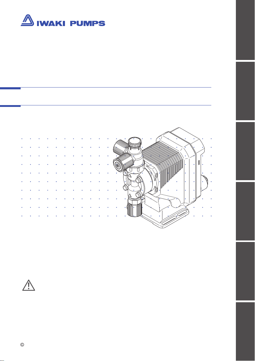
Electromagnetic Metering Pump
EJ-B(S) (Asia)
Safety instructions
Overview Installation Operation Maintenance Specication
Instruction manual
Thank you for choosing our product.
Please read through this instruction manual before use.
This instruction manual describes important precautions and
instructions for the product. Always keep it on hand for quick
reference.
Page 2
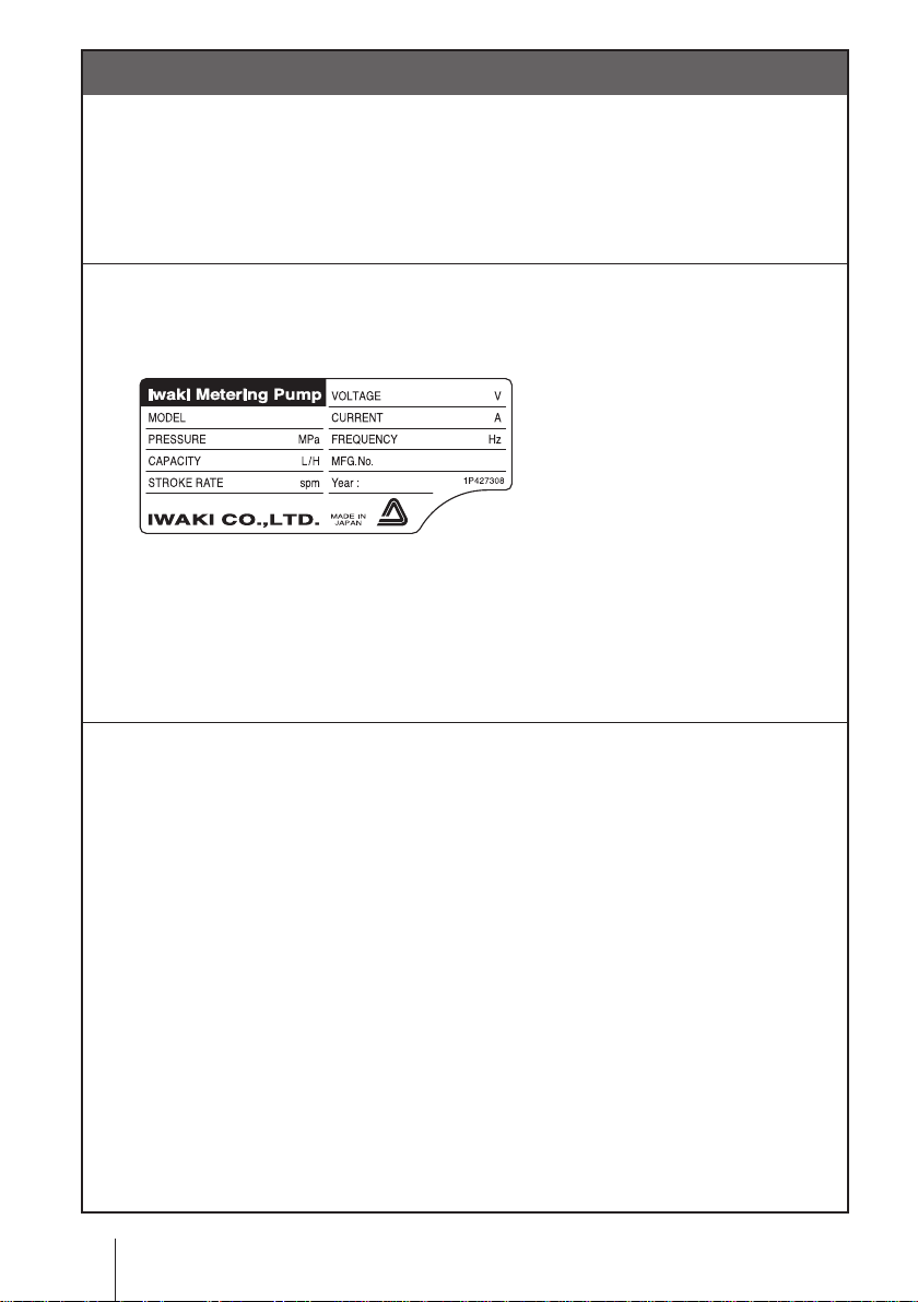
Order conrmation
Open the package and check that the product conforms to your order. If
any problem or inconsistency is found, immediately contact your distributor.
a. Check if the delivery is correct.
Check the nameplate to see if the information such as model codes, discharge capacity and discharge pressure are as ordered.
b. Check if the delivery is damaged or deformed.
Check for transit damage and loose bolts.
2
Order conrmation
Page 3

Contents
Order conrmation ............................................................................................. 2
Safety instructions .......................................................................6
Warning ............................................................................................................. 7
Caution .............................................................................................................. 8
Precautions for use ........................................................................................10
Overview ......................................................................................12
Introduction .....................................................................................................12
Pump structure & Operating principle .........................................................12
Features .......................................................................................................13
Operational functions ....................................................................................13
Manual mode ...............................................................................................13
Part names.......................................................................................................14
Pump............................................................................................................14
Operational panel ........................................................................................15
Basic displays & Pump states ................................................................16
Identication codes ........................................................................................17
Installation ..................................................................................18
Pump mounting ...............................................................................................18
Plumbing ..........................................................................................................19
Tube connection ..........................................................................................19
Check valve mounting .................................................................................21
Wiring .............................................................................................................. 23
Power voltage/Earthing .............................................................................. 23
Contents
3
Page 4

Operation .....................................................................................26
Before operation ............................................................................................ 26
Points to be checked .................................................................................. 26
Retightening of pump head xing bolts ...................................................... 26
Use of hexagon wrench instead of a torque wrench ............................. 27
Degassing ................................................................................................... 27
Flow rate adjustment .................................................................................. 30
Before a long period of stoppage (one month or more) .............................. 32
Operation programming ............................................................................... 33
Programming ow ....................................................................................... 33
Manual operation ........................................................................................ 34
Keypad lock ................................................................................................35
Keypad lock activation ........................................................................... 35
Keypad lock release .............................................................................. 35
Maintenance ................................................................................36
Troubleshooting ..............................................................................................37
Inspection ....................................................................................................... 38
Daily inspection .......................................................................................... 38
Periodic inspection ..................................................................................... 38
Wear part replacement .................................................................................. 39
Wear part list ............................................................................................... 39
Before replacement ....................................................................................40
Valve set replacement .................................................................................41
Discharge valve set dismantlement/assembly .......................................41
Suction valve set dismantlement/assembly ..........................................43
Diaphragm replacement .............................................................................44
4
Contents
Page 5

Exploded view .................................................................................................47
Pump head & Drive unit ...............................................................................47
Pump head ................................................................................................. 48
Specications/Outer dimensions ................................................................ 49
Specications .............................................................................................49
Pump unit ..............................................................................................49
Control unit ............................................................................................ 50
Power cable ........................................................................................... 50
Pump colour ..........................................................................................50
Outer dimensions.........................................................................................51
EJ-B09/-B11/-B16/-B21 VC/VH ..............................................................51
EJ-B11/-B16/-B21 TC .............................................................................52
Contents
5
Page 6
Requirement
Safety instructions
Read through this section before use. This section describes
important information for you to prevent personal injury or
property damage.
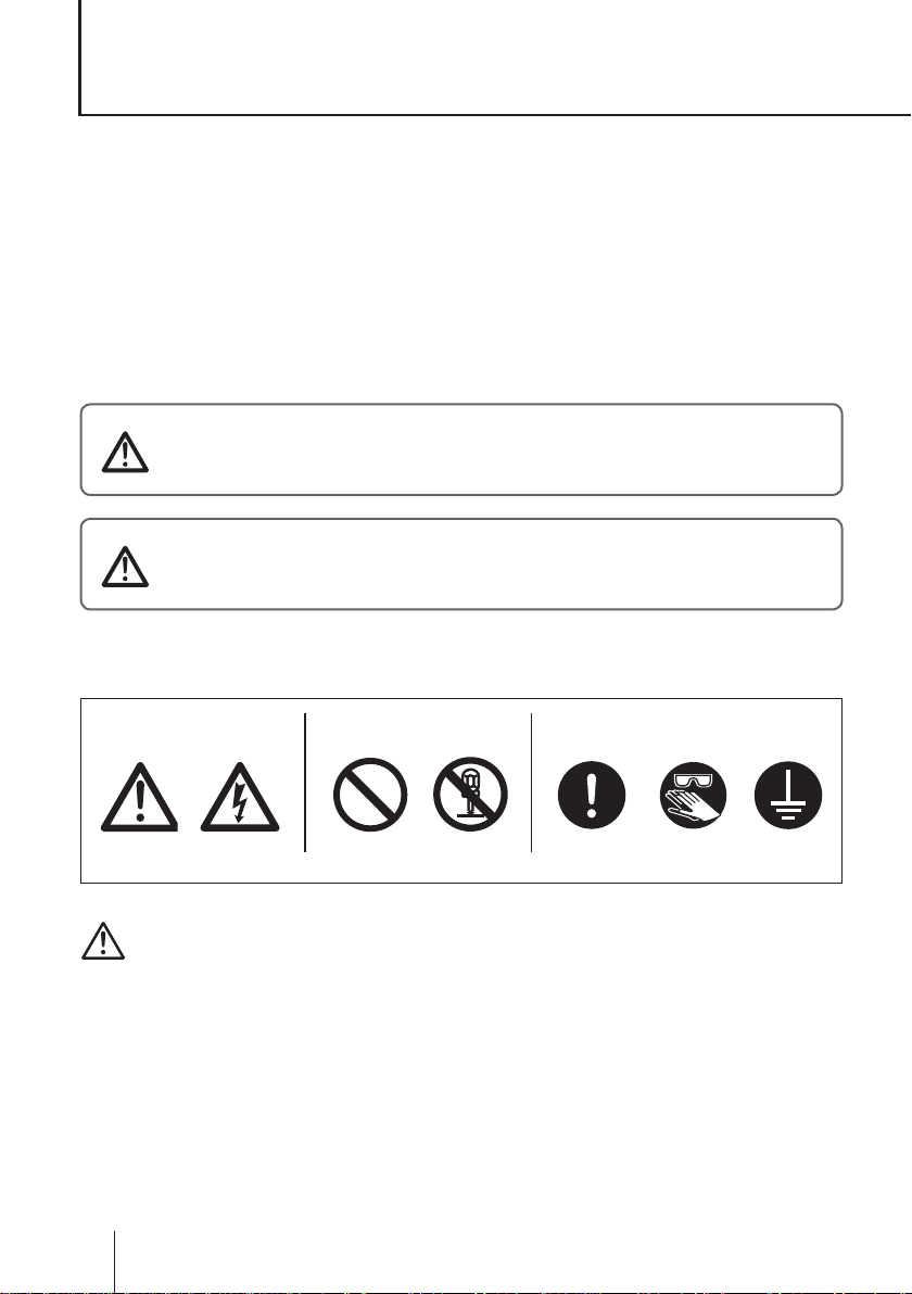
■ Symbols
In this instruction manual, the degree of risk caused by incorrect use is noted
with the following symbols. Please pay attention to the information associated
with the symbols.
WARNING
CAUTION
Indicates mishandling could lead to a fatal or seri-
ous accident.
Indicates mishandling could lead to personal injury
or property damage.
A symbol accompanies each precaution, suggesting the use of "Caution", "Pro-
hibited actions" or specic "Requirements".
Caution marks Prohibited mark Requirement mark
Caution
Electrical
shock
Prohibited
Do not rework
or alter
Wear
protection
Grounding
Export Restrictions
Technical information contained in this instruction manual might be treated
as controlled technology in your countries, due to agreements in international
regime for export control.
Please be reminded that export license/permission could be required when this
manual is provided, due to export control regulations of your country.
6
Safety instructions
Page 7
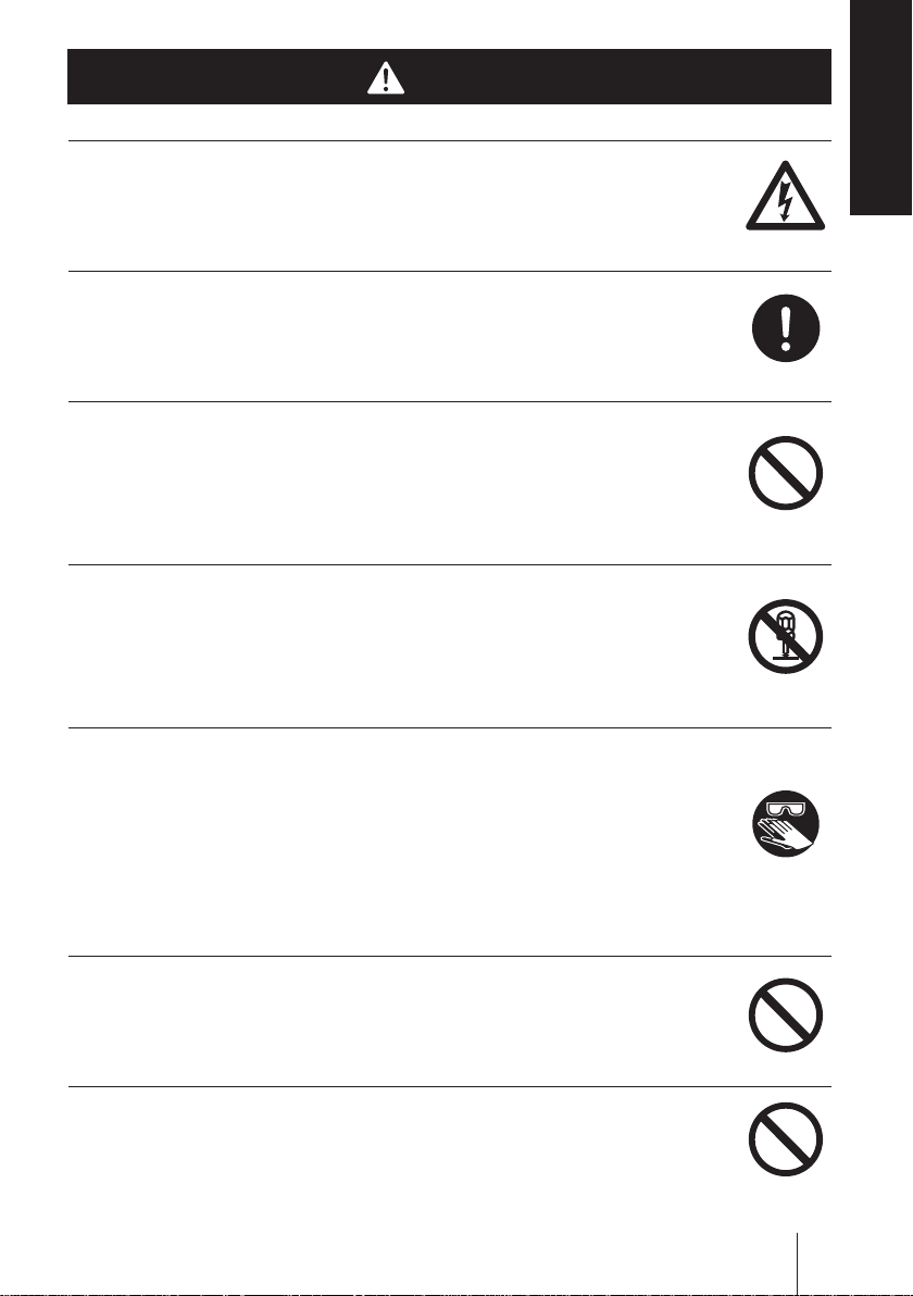
WARNING
Turn off power before service
Risk of electrical shock. Be sure to turn off power to stop the pump
and related devices before service is performed.
Stop operation
If you notice any abnormal or dangerous conditions, suspend op-
eration immediately and inspect/solve problems.
Do not use the pump in any condition other than its intended purpose
The use of the pump in any conditions other than those clearly
specied may result in failure or injury. Use this product in specied
conditions only.
Do not modify the pump
Alterations to the pump carries a high degree of risk. It is not the
manufacturer's responsibility for any failure or injury resulting from
alterations to the pump.
Electrical
shock
Requirement
Prohibited
Do not rework
or alter
Safety instructions
Wear protective clothing
Always wear protective clothing such as an eye protection, chemi-
cal resistant gloves, a mask and a face shield during disassembly,
assembly or maintenance work. The specic solution will dictate the
degree of protection. Refer to MSDS precautions from the solution
supplier.
Do not damage the power cable
Do not pull, knot, or crush the power cable. Damage to the power
cable could lead to a re or electrical shock if cut or broken.
Do not operate the pump in a ammable atmosphere
Do not place explosive or ammable material near the pump.
WARNING
Wear
protection
Prohibited
Prohibited
7
Page 8

CAUTION
Qualied personnel only
The pump should be handled or operated by qualied personnel with a
full understanding of the pump. Any person not familiar with the prod-
uct should not take part in the operation or maintenance of the pump.
Use specied power only
Do not apply power other than that specied on the nameplate. Other-
wise, failure or re may result. Ensure the pump is properly grounded.
Do not run pump dry
Do not run pump dry for more than 30 minutes (even when the
pump runs for degassing). Otherwise, the pump head xing screws
may loosen and liquid may leak. Optimise your system. If the pump
runs dry for a long period (for more than 30 minutes), the pump
head and the valve cases may deform by friction heat and conse-
quently leakage results.
Requirement
Prohibited
Caution
Keep electric parts and wiring dry
Risk of re or electric shock. Install the pump where it can be kept dry.
Ventilation
Fumes or vapours can be hazardous with certain solutions. Ensure
proper ventilation at the operation site.
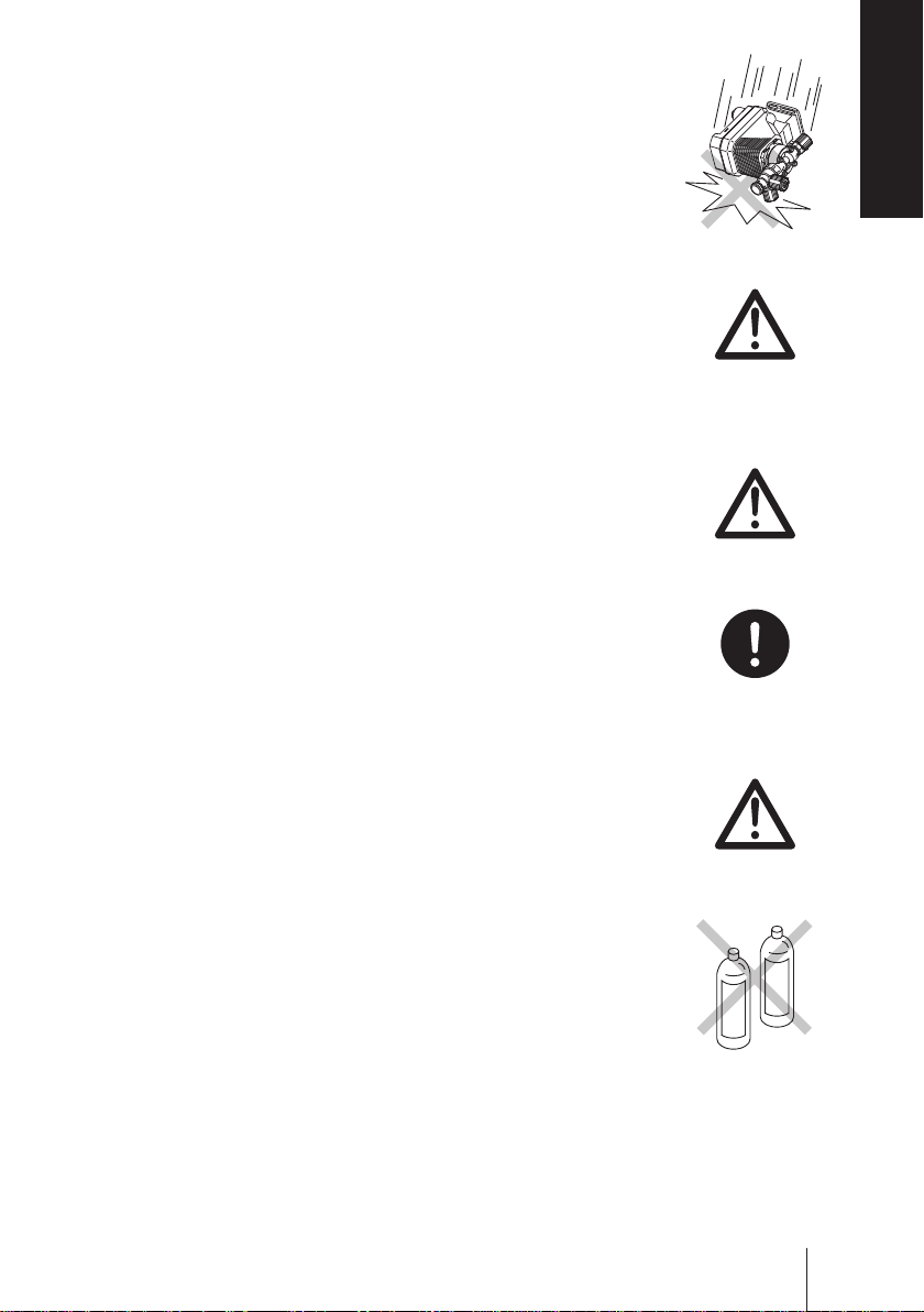
Do not install /store the pump:
• In a ammable atmosphere or a dusty/humid environment.
• Where ambient temperature can exceed 0-40ºC.
• In direct sunlight or wind & rain.
Spill precautions
Ensure protection and containment of solution in the event of
plumbing or pump damage (secondary containment).
8
CAUTION
Prohibited
Caution
Prohibited
Requirement
Page 9
Do not use the pump in a wet location
The pump is not waterproof. Use of the pump in wet or extremely
humid locations could lead to electric shock or short circuit.
Grounding
Risk of electrical shock! Always properly ground the pump. Con-
form to local electric codes.
Install a GFCI (earth leakage breaker)
An electrical failure of the pump may adversely affect other de-
vices on the same line. Purchase and install a GFCI (earth leakage
breaker) separately.
Preventative maintenance
Follow instructions in this manual for replacement of wear parts. Do
not disassemble the pump beyond the extent of the instructions.
Prohibited
Grounding
Electrical
shock
Requirement
Safety instructions
Do not use a damaged pump
Use of a damaged pump could lead to an electric shock or death.
Disposal of a used pump
Dispose of any used or damaged pump in accordance with local
rules and regulations. If necessary, consult a licensed industrial
waste disposal company.
Check pump head bolts
Liquid may leak if any of the pump head bolts become loose.
Tighten the bolts diagonally and evenly by 2.16N•m before initial
operation and at regular intervals.
Install a relief valve
Install a relief valve on a discharge line near the pump so as to
release the discharge pressure when it exceeds the maximum level.
CAUTION
Prohibited
Requirement
Caution
Requirement
9
Page 10

Precautions for use
• Electrical work should be performed by a qualied electri-
cian. Otherwise, personal injury or property damage could
result.
• Do not install the pump:
–In a ammable atmosphere.
–In a dusty/humid place.
–In direct sunlight or wind & rain.
– Where ambient temperature can exceed 0-40ºC.
Protect the pump with a cover when installing it out of
doors.
• Select a level location, free from vibration, that won't hold
liquid. Anchor the pump with four M5 bolts so it doesn't
vibrate. If the pump is not installed level, output may be
affected.
Caution
• When two or more pumps are installed together, vibration
may be signicant, resulting in poor performance or failure.
Select a solid foundation (concrete) and fasten anchor bolts
securely to prevent vibration during operation.
• Allow sufficient space around the pump for easy access
and maintenance.
• Install the pump as close to the supply tank as possible.
• When handling liquids that generate gas bubbles (sodium
hypochlorite or hydrazine solution), install the pump in a
cool and dark place. Flooded suction installation is strongly
recommended.
10
Precautions for use
Caution
Caution
Caution
Caution
Page 11
• Use care handling the pump. Do not drop. An impact may
affect pump performance. Do not use a pump that has
been damaged to avoid the risk of electrical damage or
shock.
• The pump has a rating of IP65 equivalent, but is not water-
proof. Do not operate the pump while wet with solution or
water. Failure or injury may result. Immediately dry off the
pump if it gets wet.
• Do not close discharge line during operation. Solution may
leak or piping may break. Install a relief valve to ensure
safety and prevent damaged plumbing.
• Solution in the discharge line may be under pressure.
Release the pressure from the discharge line before dis-
connecting plumbing or disassembly of the pump to avoid
solution spray.
Safety instructions
Caution
Caution
Requirement
• Wear protective clothing when handling or working with
pumps. Consult solution MSDS for appropriate precautions.
Do not come into contact with residual solution.
• Do not clean the pump or nameplate with a solvent such
as benzine or thinner. This may discolor the pump or erase
printing. Use a dry or damp cloth or a neutral detergent.
Precautions for use
Caution
Thinner
Benzine
11
Page 12
Overview
Pump characteristics, features and part names are described
in this section.
Introduction
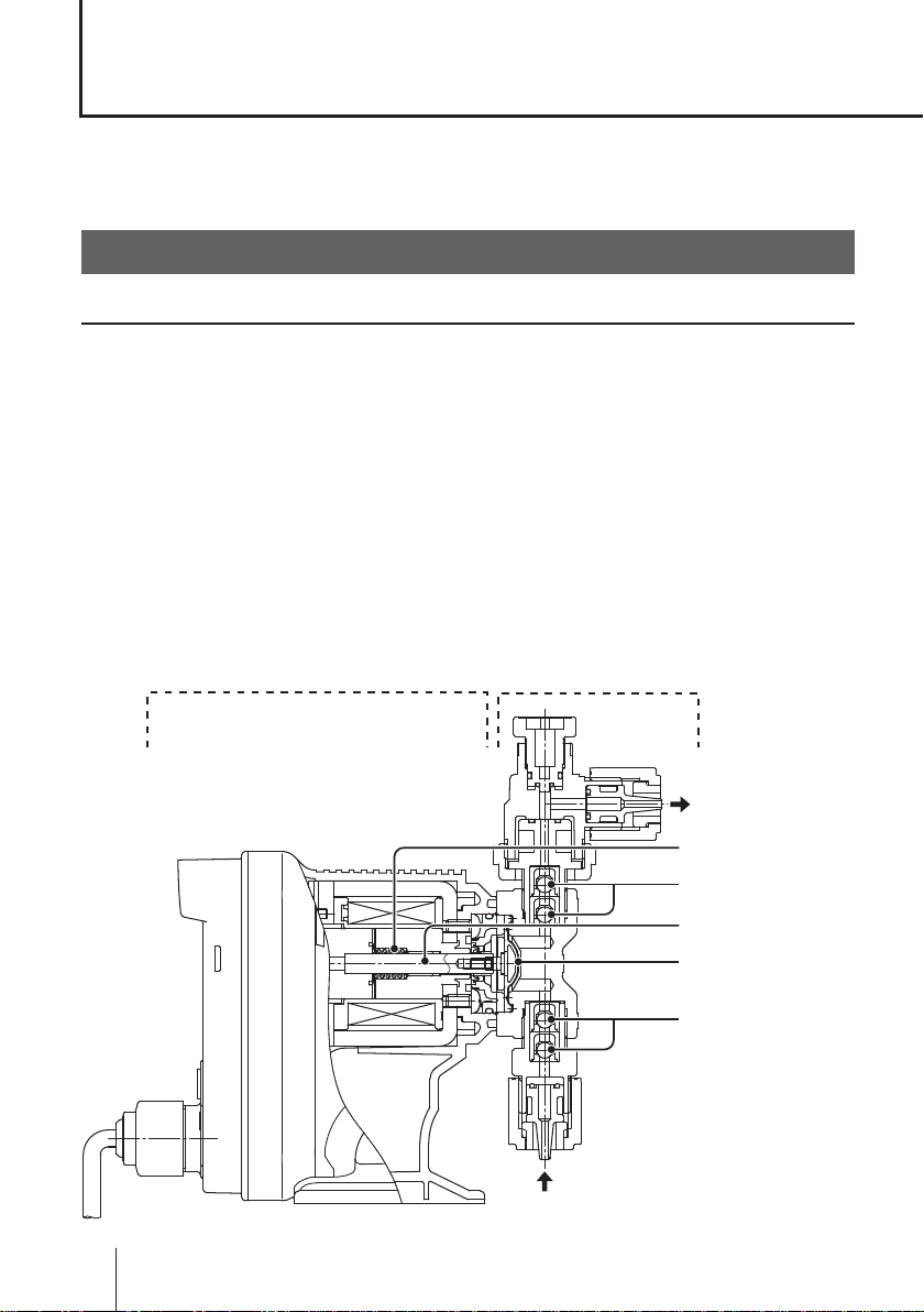
Pump structure & Operating principle
The EJ series is a diaphragm metering pump which consists of a pump head
and a drive unit with a built-in controller. A diaphragm is directly driven by electromagnetic force.
Principle of operation
The pulse signal via the PCB generates the electromagnetic force to make
reciprocating motion with the assistance of the spring force. The reciprocating
motion is transferred to a diaphragm through a plunger and then volumetric
change occurs in the pump head. This action transfers liquid along with pump
head valve action.
Control unit Pump head
12
Introduction
OUT
Spring
Pump head valve
Plunger
Diaphragm
Pump head valve
IN
Page 13
Features
● Multivoltage operation
The EJ series is a multivoltage type (100-240VAC) and can be selected with-
out local power limitations.
● High turndown ratio
Digitally-controlled spm range is 1-360spm.
● IP rating of 65 equivalent
This pump is not waterproof. Protect the pump with a cover when installing it
out of doors.
Operational functions
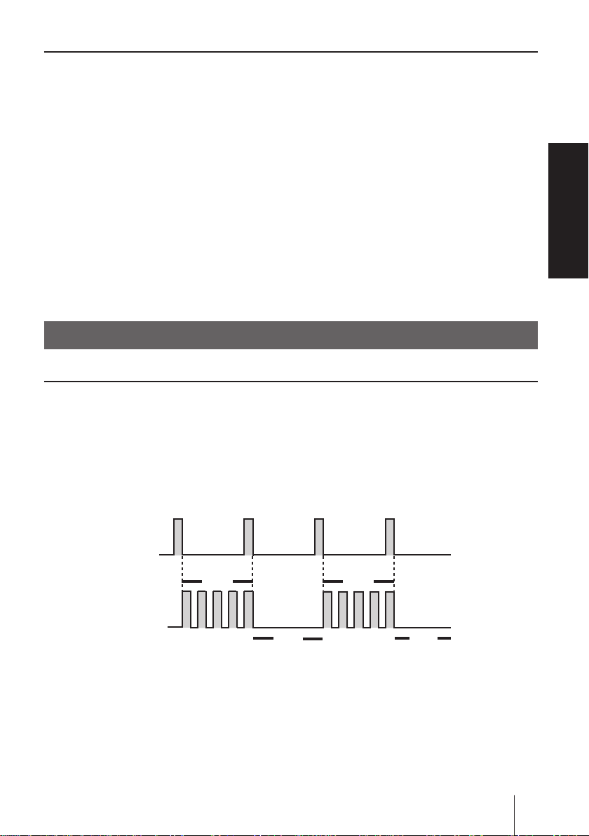
Manual mode
Run/stop the pump by the start/stop key. A stroke rate (MAN speed) can be
changed in the range of 1-360spm by the up key at any time during operation
or stop. See page 34 for detail.
*The pump can also be turned ON/OFF by switching the main power.
Overview
Key operation
(Start/Stop key)
Pump operation
Run Run
Stop
Stop
Operational functions
13
Page 14
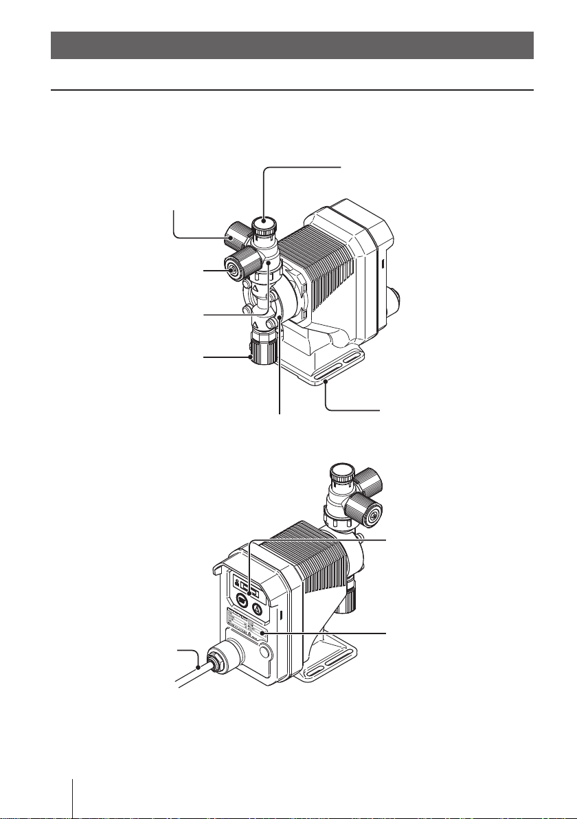
Part names
Pump
Air vent por t
Always connect a tube. Be sure
to return the tube end to a supply
tank or a container.
A circumferential direction of the
port can be changed up to 90
degrees counterclockwise from
the original position.
Outlet
Air vent body
Inlet
Adjusting screw
Used for opening the air vent port.
14
Part names
Power cable
Pump head
Base
Always fix with bolts.
Control unit
Used for the start/stop of
the pump and stroke rate
adjustment.
Nameplate
Describes the pump
specifications.
Page 15

Operational panel
ON LED
Lights as turning on power
and flashes at each stroke.
Display
Stroke rate and operational
status are shown here.
ON
START
STOP
UP key
Used for increasing numeric values. If this key is kept pressed, the
value rises faster. The EJ doesn't
have the DOWN key, so if you
want a lower spm, first get to the
max 360 spm and then push this
key once. The spm will return to 1.
Overview
START/STOP key
Used for starting/stopping the pump.
Part names
15
Page 16
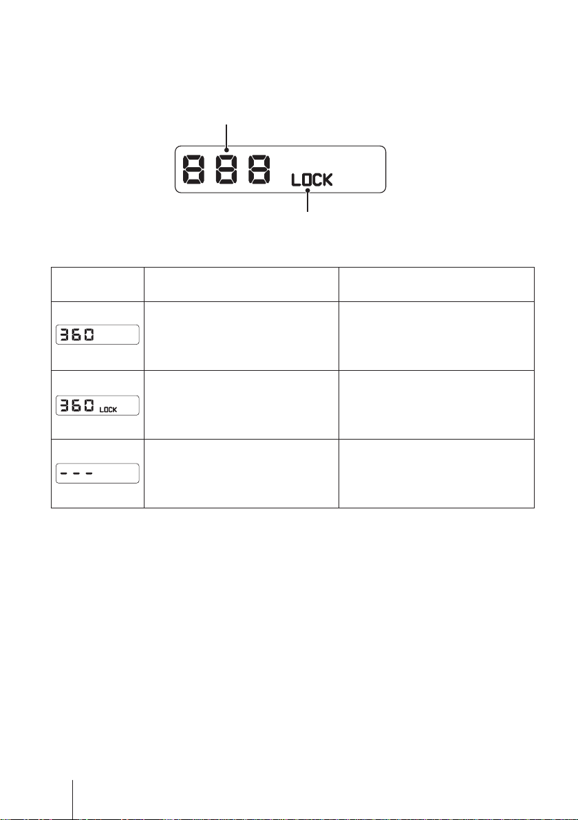
■ Basic displays & Pump states
Shows a pump speed in spm. The spm
flashes during operation in MAN mode.
The indication changes to "- - -" when the
pump enters maintenance mode.
Represents keypads are locked.
Display info ON LED lights
A wait state in MAN mode:
The display shows the MAN
speed in spm.
―
The pump is in maintenance
mode. When extending the diaphragm, the display ashes.
ON LED ushes
(in sync with each shot)
Operation in MAN mode:
A current spm ashes (not in
sync with a pump shot).
Keypads are locked and any key
operation is cancelled.
―
16
Part names
Page 17
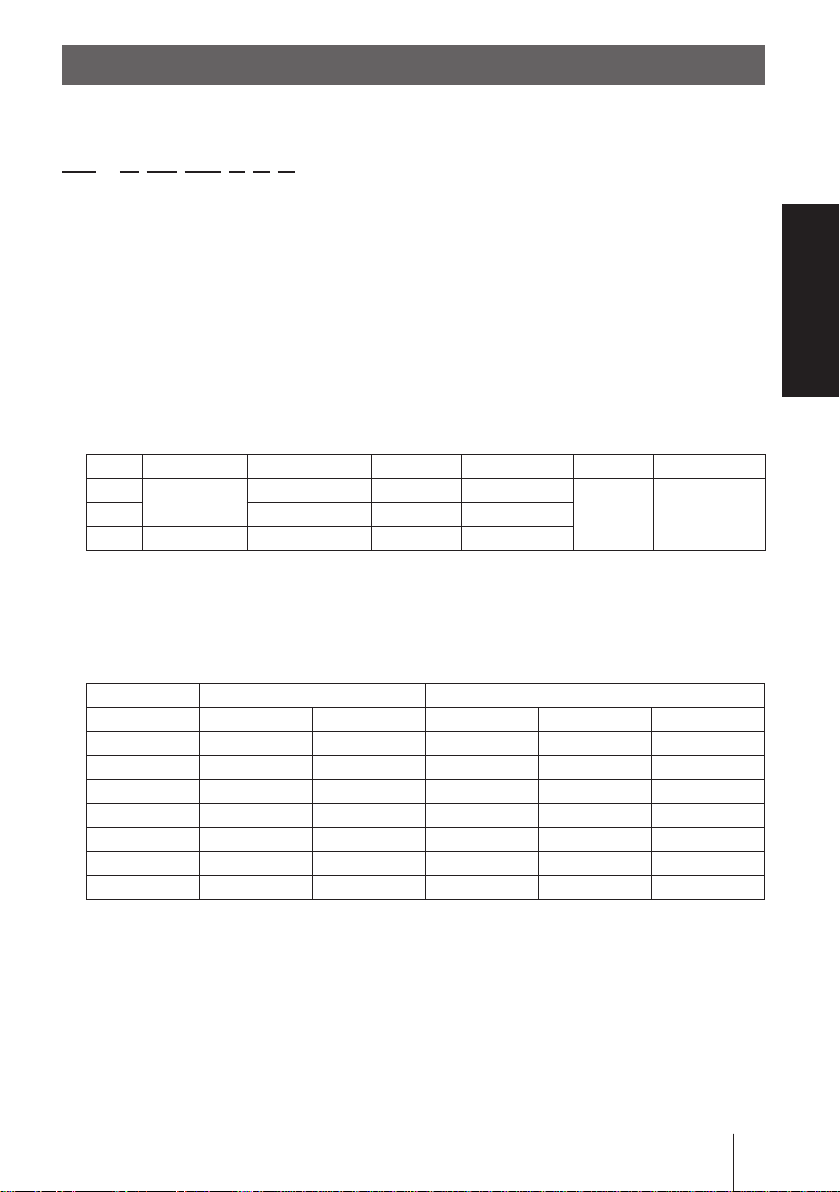
Identication codes
The model codes of the pump/drive units represent the following information.
EJ - B 11 VC 1 J S _ - _ _
a b c d e f g h i
a. Series name
EJ: Multivoltage electromagnetic metering pump
b. Drive unit (Average power consumption)
B: 15W
c. Diaphragm effective diameter
09: 8mm 11: 10mm 16: 15mm 21: 20mm
d. Wet end materials
Code Pump head Valve O ring Valve seat Gasket Diaphragm
VC
VH HC276 EPDM EPDM
TC PVDF Alumina ceramic FKM FKM
Material code
PVC : Transparent polyvinyl chloride HC276 : HASTELLOY C276
FKM : Fluorine-contained rubber EPDM : Ethylene-propylene rubber
PTFE : Polytetrauoroethylene PVDF : Polyvinylidene diuoride
PVC
Alumina ceramic FKM FKM
PTFE
PTFE + EPDM
(dry end)
e. Tube size
Area Asia Australia
Material VC VH VC VH TC
No code - - ø6×ø8 ø6×ø8 ø6×ø8
1 ø4×ø9 ø4×ø9 ø4×ø9 ø4×ø9 2 ø4×ø6 ø4×ø6 ø4×ø6 ø4×ø6 ø4×ø6
3 ø6×ø8 ø6×ø8 ø6×ø8 ø6×ø8 ø6×ø8
7 - - ø¼"×ø⅜" ø¼"×ø⅜" ø¼"×ø⅜"
23 - - ø6×ø12 - 24 - - ø5×ø8 - ø5×ø8
Overview
f. Power cable
J: Asian type A: Australian type
g. Control unit function
R: With external control
h. Special version
i. Special conguration
Identication codes
17
Page 18

Installation
This section describes the installation of the pump, tubing and
wiring. Read through this section before work.
Observe the following points when installing the pump.
• Risk of electrical shock. Be sure to turn off power to stop the pump and
related devices before service is performed.
• If you notice any abnormal or dangerous conditions, suspend operation
immediately and inspect/solve problems.
• Do not place explosive or ammable material near the pump.
• Do not use a damaged pump. Use of a damaged pump could lead to an
electric shock or death.
Pump mounting
Select an installation location and mount the pump.
Necessary tools
• Four M5 bolts (pump mounting)
• Adjustable wrench or spanner
Select a suitable place.
1
Select a level location, free from vibration, that won't hold liquid. See
page 10 for detail. Flooded suction is recommended when handling a
gaseous liquid such as sodium hypochlorite.
Anchor the pump with the M5 bolts.
2
Be sure to x the pump at four points.
NOTE
Select a level location. If the pump is not installed level,
output may be affected.
18
Pump mounting
Page 19

Plumbing
Connect tubes to the pump and install a check valve.
Before operation
• Cut the tube ends at.
Necessary tools
• Adjustable wrench or a spanner
Tube connection
a. Pass a tube into the tting nut and
stopper and then slide it down to the
adapter as far as it will go.
b. Put the tube end (adapter) in the t-
ting. Then hand tighten the tting nut.
c. Retighten the tting nut by turning it
further 180 degrees with an adjust-
able wrench or spanner (crush tube
mount).
Tube end (side view)
Installation
Tube
Fitting nut
Stopper
a
b
Adapter
Fitting
* Do not use excessive force to the plastic fitting nut.
* In your try to remove the connection, the adapter may be stuck in the crushed
tube and the stopper. Try not to damage the taper of the adapter that is crushing the tube against the stopper. If it has been damaged, contact us for the new
adapter/stopper.
* Do not reuse the same tube end for the crush sealing. Cut it off for ensuring
the new seal is established.
Plumbing
19
Page 20

Connect tubes into the inlet and
1
outlet.
Connect an air bleed tube into the
2
air vent port.
Route back the other tube end to a
supply tank or a container.
Outlet
Tube
Inlet
Tube
Air vent port
Air bleed tube
Determine an air vent port direction.
3
The air vent port can rotate 90 de-
grees.
a. Turn the lock nut anticlockwise.
b. Adjust the direction of the air vent
port.
c. Hand-tighten the lock nut, holding
the air vent body A.
d. Turn the lock nut 90 degrees
clockwise further with an adjustable
wrench or spanner.
20
Plumbing
Air vent port
Air vent body A
Lock nut
Page 21

Check valve mounting
Install an optional check valve to the EJ for the prevention of a back ow, siphon
and overfeeding. In the following cases be sure the check valve is installed.
• A suction side liquid level is higher than a discharge side or an injection point
at atmospheric pressure.
Suction side
Discharge side
• A discharge side liquid level is higher than a suction side but the distance is
5m or below.
5m or below
Discharge side
Suction side
• A suction line pressure is higher than a discharge line pressure.
Installation
• A discharge pressure (including pipe resistance and discharge head) is below
0.13MPa .
Plumbing
21
Page 22

Mount a check valve at the discharge tube end.
1
* The CAN check valve has the R1/2 and R3/8 thread connections as well as an
O.D.9mm tube connection. Cut off an unused part and adjust the connection
length as necessary.
CAN check valve
O.D.9mmR1/2
R3/8
* The CBN check valve (both ends tube connections) is optionally available.
Contact us or your nearest distributor.
CBN check valve
NOTE
• Periodically clean or replace a check valve with new one for the prevention of crystal
clogging, especially when using sodium hypochlorite.
• In the nature of the pump, the lower discharge pressure, the higher discharge capacity
(and vice versa). If you want to observe the max discharge capacity at any low level of
system (/discharge) pressure, use the check/back pressure valve to give the additional
pressure of 0.17MPa±0.04 to the discharge line or reduce the pump speed/stroke length.
Tubing layout
Flooded suction application Suction lift application
Air vent line
Relief valve
Check valve
Accumulator/Chamber
Pump
Relief valve
Check valve
Accumulator/Chamber
Pump
Air vent line
NOTE
Flooded suction installation is strongly recommended when handling liquids that generate gas bubbles (sodium hypochlorite or hydrazine solution).
22
Plumbing
Page 23

Wiring
Wiring for a power voltage, earthing and an external signal.
Observe the following points during wiring work.
• Electrical work should be performed by a qualied electrician. Always
observe local electric codes.
• Observe the rated voltage range, or the electrical circuit in the control
unit may fail.
• Do not perform wiring work while electric power is ON. Otherwise, an
electrical shock or a short circuit may result. Be sure to turn off the power
before wiring work.
• Be careful for the power not to be turned on during work.
• The power cable is not replaceable.
Necessary tools
• Adjustable wrench or spanner • Phillips screw driver
Power voltage/Earthing
Installation
Check that the main power is turned off.
Connect the power/earth cables via crimp contacts (in Asia), or
1
plug the pump into the outlet (in Australia).
*Make sure the pump is earthed properly.
Wiring
23
Page 24

NOTE
TIME
• Do not share a power source with a high power device which may generate surge
voltage. Otherwise an electronic circuit may fail. The noise caused by an inverter also
affects the circuit.
• Energize the pump with a power voltage via a mechanical relay or switch. Do not
uctuate the voltage, or CPU may malfunction. See page 25 for the precautions for
ON-OFF control by a mechanical relay.
Apply power sharply Do not apply gradually
POWER
ON
OFF
POWER
TIME
ON
OFF
Surge voltage
The electronic circuit in this pump may fail due to surge voltage. Do not
place the pump close to a high power device of 200V or more which may
generate large surge voltage. Otherwise, take any of the following meas-
ures.
• Install a surge absorption element (ex. a varister with capacity of 2000A
or more) via power cable.
Surge absorption element
Recommended varisters
SUNTAN TSV14D511K
Panasonic E R Z V14D511
See manufacturer's catalogues for detail.
• Install a noise cut transformer via power cable.
Noise cut transformer
24
Wiring
Page 25

Precautions for ON-OFF control by a mechanical relay
This pump is equipped with CPU. Observe the following points when ON-
OFF control is performed:
• Do not turn ON/OFF power voltage more than six times per hour.
• When using a mechanical relay for ON-OFF operation, its contact capac-
ity should be 5A or more. Contact point may fail if it is less than 5A.
• If a mechanical relay with the contact capacity of 5A is used, the maxi-
mum allowable ON/OFF operation is about 150,000 times. The contact
capacity should be 10A or more when making ON-OFF operation over
150,000 times or sharing a power source with a large capacity equip-
ment. Otherwise a contact point may fail by surge voltage.
• Use a solid state relay (SSR) as necessary (such as the OMRON G3F).
See manufacturer's catalogues for detail.
Installation
Wiring
25
Page 26

Operation
This section describes pump operation and programming.
Run the pump after plumbing and wiring are completed.
Before operation
Check a ow rate, tubing and wiring. And then perform degassing and ow rate
adjustment before starting operation.
Points to be checked
Before operation, check if...
• Liquid level in a supply tank is enough.
• Tubing is securely connected and is free from leakage and clogging.
• Discharge/suction valves are opened.
• A power voltage is in the allowable range.
• Electrical wiring is correct and is free from the risk of short circuit and electri-
cal leakage.
Retightening of pump head xing bolts
Important
The pump head xing bolts may loosen when plastic parts creep due to tem-
perature change in storage or in transit, and this can lead to leakage. Be sure
to retighten the bolts evenly to 2.16N•m in diagonal order before starting opera-
tion.
*Tighten xing bolts once every three months.
26
Before operation
Page 27

■ Use of hexagon wrench instead of a torque wrench
Fasten the xing bolts as tight as can be by the hand with the straight long part
of a hexagon wrench (a) and further turn the bolts clockwise 90 degrees with
the short part (b).
a b
Straight long
part
Short part
90°
Degassing
The gas needs to be expelled from the pump and tubing by degassing. Normal
performance can not be obtained with gas in the pump. Conduct degassing in
the following cases.
• When the pump starts to run for the rst time
• When a ow rate is too low
• After liquid is replaced in a supply tank
• After a long period of stoppage
• After maintenance and inspection
Operation
NOTE
• Both gas and chemical come out together through an air bleed tube. Place the end of
the tube in a supply tank or a container.
• Some chemicals may cause skin trouble or damage component parts. When your
hand or component parts get wet with chemical liquid, wipe off immediately.
Before operation
27
Page 28

Points to be checked
• An air bleed tube is connected to the pump.
Turn on power.
1
The LED lights and a display related to the
current mode appears on the screen.
* The pump waits in the MAN mode when the
power is turned ON with a default setting or calls
up the last selected mode or condition.
Use the UP key to set a stroke rate to 360spm.
2
• This programming is not necessary when the display already shows
360. Move to the next step.
• If the key is pressed and held, the spm will quickly increases to the
max rate.
Air bleed tube
ON
LED
START
STOP
Rotate the adjusting screw two revolutions
3
anticlockwise to open the air vent port.
* Do not rotate it three revolutions. Otherwise,
liquid may come out from the adjusting screw.
28
Before operation
Adjusting screw
Page 29

Push the start/stop key and run the pump for more than ten minutes.
4
ON
START
STOP
Push the start/stop key and stop the pump.
5
Rotate the adjusting screw clockwise to close the air vent port.
6
Check liquid is discharged.
7
*Degassing is required again if the pump does not discharge liquid.
Check connections for leakage.
8
Degassing has now been completed.
ON
START
STOP
Operation
Before operation
29
Page 30

Flow rate adjustment
A ow rate can be adjusted only by changing a stroke rate (stroke length
adjustment is not available). A stroke rate can be set by keypad operation from
1 to 360spm. The relation between a ow rate* and a stroke rate is shown as
below.
100
%
Flow rate
75
50
25
* The discharge capacity described on
the nameplate is the value at 100%.
0
Turn on power and call up manual
1
180 360 spm
Stroke rate
mode.
Enter manual mode to indicate a
stroke rate on the screen.
Determine a stroke rate that will meet a required ow.
2
See the above table.
ON
START
STOP
30
Before operation
Page 31

Use the UP key to adjust a stroke rate.
3
• spm increases as pushing the UP keys.
• Press and hold the key for three seconds for quick increment. Quick
increment stops at 360spm. 360spm skips to 1spm when the key is
released and pushed once.
ON
START
STOP
Measure a ow rate.
4
If a ow rate is lower than a specied level, increase a stroke rate.
5
Measure the ow again to see the specied level is obtained.
6
ON
START
STOP
Operation
Before operation
31
Page 32

Before a long period of stoppage (one month or more)
Clean wet ends and the inside of tubing.
• Run the pump with clean water for about 30 minutes to rinse chemicals off
from the pump head and piping.
Before unplugging the pump
• Always stop the pump by key operation and wait for three seconds before
unplugging the pump. Otherwise, the last key operation may not be put in
memory. In this case the pump unintentionally starts to run as powered on,
discharging liquid.
When the pump does not transfer liquid at resuming operation.
• Clean the valve sets and remove foreign matters.
• If gas is in the pump head, expel gas and readjust a ow rate. See "Degas-
sing" on page 27 and "Flow rate adjustment" on page 30 for detail.
32
Before operation
Page 33

Operation programming
Operation at each mode is individually set and controlled by keypad operation.
Select a proper mode to make optimal operation.
Programming ow
Maintenance mode
3 sec.
Power ON
WAIT mode
Power ON while the UP key is pressed.
The maintenance mode will come up
after 3 seconds.
Display flashes and diaphragm
is extended to the full.
spm setting
Operation
MAN mode
Keypad lock (Ex.)
MAN mode operation
3 sec
3 sec
* The maintenance mode is used for the replacement of a diaphragm.
Keypads are locked.
Operation programming
33
Page 34

Manual operation
Turn on power.
1
The LED lights and a display related to
the current mode appears on the screen.
* The pump waits in the manual mode when
the power is turned ON with a default setting or calls up the last selected mode or
condition.
Use the UP key to set a stroke rate.
2
• spm increases as pushing the UP key.
• Press and hold the key for three seconds for quick increment. Quick
increment stops at 360spm. 360spm skips to 1spm when the key is
released and pushed once.
ON
START
STOP
ON
START
STOP
Push the start/stop key.
3
The LED and spm indication blink as the pump starts to run.
*Only the LED blinks in sync with the pump operation.
ON
START
STOP
34
Operation programming
ON
START
STOP
ON
START
STOP
Page 35

Keypad lock
Keypad lock can be active in the MAN mode for the prevention of erroneous
key operation. The "LOCK" indication appears while keypads are locked.
NOTE
Any key operation is not acceptable when the keypads are locked. In an emergency,
unplug the pump to stop operation. Plugging in the pump, keypads are locked again.
■ Keypad lock activation
Press and hold the start/stop key for three seconds.
1
ON
START
STOP
ON
START
STOP
3 sec
■ Keypad lock release
Press and hold the start/stop key for three seconds.
1
Keypad lock is released and key operation becomes acceptable.
ON
START
STOP
ON
START
STOP
3 sec
Operation
Operation programming
35
Page 36

Maintenance
This section describes troubleshooting, inspection, wear part
replacement, exploded views and specications.
Important
• Follow instructions in this manual for replacement of wear parts. Do not
disassemble the pump beyond the extent of the instructions.
• Always wear protective clothing such as an eye protection, chemical re-
sistant gloves, a mask and a face shield during disassembly, assembly or
maintenance work. The specic solution will dictate the degree of protec-
tion. Refer to MSDS precautions from the solution supplier.
• Risk of electrical shock. Be sure to turn off power to stop the pump and
related devices before service is performed.
Before unplugging the pump
Always stop the pump by key operation. And wait for three seconds before
unplugging the pump. Otherwise, the last key operation to stop the pump
may not be put in memory. In this case the pump unintentionally starts to
run as powered on, discharging liquid.
36
Maintenance
Page 37

Troubleshooting
First check the following points. If the following measures do not help removing
problems, contact us or your nearest distributor.
States Possible causes Solutions
The pump
does not run
( blank LED
or screen).
Liquid can
not be
pumped up.
A ow rate
uctuates.
Liquid leaks. The tting or the air vent body is
Power voltage is too low. • Observe the allowable voltage
range of 90-264VAC
The pump is not powered. • Check the switch if it is installed.
• Correct wiring.
• Replace a breaking wire to new
one.
A PCB has failed. • Replace the pump.
Air lock in the pump • Expel air. See page 27.
Air ingress through a suction line. • Correct tubing.
A valve set is installed upside
down.
Valve gaskets are not installed. • Install valve gaskets.
Foreign matters are stuck in the
pump head valves.
A ball valve is stuck on a valve
seat.
Air stays in the pump head. • Expel air. See page 27.
Overfeeding occurs. • Mount a check valve. See page
Foreign matters are stuck in the
pump head valves.
Diaphragm is broken. • Replace diaphragm.
Pressure uctuates at an injection
point.
mounted loose.
The pump head is mounted loose. • Retighten as necessary. See page
O rings or valve gaskets are not
installed.
Diaphragm is broken. • Replace the diaphragm.
Excessive discharge pressure. • Check that a discharge line is not
• Reinstall the valve set.
• Dismantle, inspect and clean the
valves. Replace as necessary.
• Dismantle, inspect and clean the
valve. Replace as necessary.
21.
• Dismantle, inspect and clean the
valves. Replace as necessary.
• Maintain a pressure constant at
an injection point by optimizing
tubing or by relocating the point.
• Retighten as necessary.
26.
• Install O rings and valve gaskets.
closed.
• Check if tubing is not clogged.
Maintenance
Troubleshooting
37
Page 38

Inspection
Perform daily and periodic inspection to keep pump performance and safety.
Daily inspection
Check the following points. Upon sensing abnormality, stop operation immediately and remove problems according to "Troubleshooting".
When wear parts come to the life limit, replace them with new ones. Contact us
or your nearest distributor for detail.
No. States Points to be checked How to check
1 Pumping • If liquid is pumped. Flow meter or visual
inspection
• If the suction and discharge pressure
are normal.
• If liquid has deteriorated, crystallized
or precipitated.
2 Noise and vibration • If abnormal noise or vibration occurs.
They are signs of abnormal operation.
3 Air ingress from
pump head joints
and a suction line
• If leakage occurs.
• If pumped liquid includes air bubbles,
check lines for leakage and retighten
as necessary.
Check specications.
Visual or audio
inspection
Visual or audio
inspection
Visual or audio
inspection
Periodic inspection
Retighten the pump head mounting bolts evenly to the 2.16N•m in diagonal
order (once three months).
* Mounting bolts may loosen in operation. How fast the bolts start to loosen is depend-
ing on operating conditions.
*A hexagon wrench can be used for a torque wrench. See page 27.
38
Inspection
Page 39

Wear part replacement
13
To run the pump for a long period, wear parts need to be replaced periodically.
It is recommended that the following parts are always stocked for immediate
replacement. Contact us or your nearest distributor for detail.
Precautions
• Solution in the discharge line may be under pressure. Release the pres-
sure from the discharge line before disconnecting plumbing or disassem-
bly of the pump to avoid solution spray.
• Rinse wet ends thoroughly with tap water.
• Each time the pump head is dismantled, replace the diaphragm, O rings,
and valve sets with new ones.
Wear part list
Parts # of parts Estimated life
12
9
11
Valve set 2 sets
Pump
10
9
11
10
8000 hours
19
20
6
18
26
Wear part replacement
Diaphragm 1
O ring See page 48.
* Wear part duration varies with the pressure, temperature and characteristics of liquid.
* The estimated life is calculated based on the continuous operation with clean water at
ambient temperature.
Maintenance
39
Page 40

Before replacement
First release pressure from the pump head.
Stop the pump operation.
1
Rotate the adjusting screw two revolutions anticlockwise to open
2
the air vent port.
NOTE
Do not rotate it three revolutions or more. Otherwise, the adjusting screw may
come off with solution spray.
Check the discharge line and the pump head are depressurized.
3
Liquid pressure is released from the air vent port in the form of solution
spray.
NOTE
If pressurized liquid is not expelled, run the pump with an opened air vent port
until pressure is removed.
40
Wear part replacement
Page 41

Valve set replacement
■ Discharge valve set disassembly/assembly
Necessary tools
• Adjustable wrench or spanner
• 21mm box wrench
• A pair of tweezers
*Unx the pump base before disassembly.
Loosen the tting nut to remove a dis-
1
charge tube and an air bleed tube.
NOTE
Wash out residual liquid or substances.
Turn the lock nut anticlockwise by
2
an adjustable wrench and remove
the air vent body A.
Air bleed tube
Fitting nut
Discharge tube
Lock nut
Air vent body A
Maintenance
Wear part replacement
41
Page 42

Remove the air vent body B with a 21mm box wrench.
3
Pull out the valve set by a pair of tweezers.
4
Air vent body B
Place a new valve set into the pump head and
5
screw the air vent body B through the lock nut.
* Be careful not to misarrange the valve set or place
upside down. Otherwise, leakage or ow rate reduc-
tion may result.
* Do not forget to t O rings and gaskets.
* Keep the valve set free from dust or foreign matters.
Remount the air vent body A and connect tubes.
6
Air vent body B
Lock nut
Valve set
4
5
12
9
11
10
9
11
10
13
42
Wear part replacement
Page 43

■ Suction valve set disassembly/assembly
NOTE
Be careful not to drop the valve set.
Remove the tting nut and the suction tube.
1
NOTE
Wash out residual liquid or substances.
Remove the tting by an adjustable wrench
2
or a spanner.
Fitting
Pull out the valve set from the tting by a pair of tweezers.
3
Fitting nut
Suction tube
Place a new valve set into the tting. Hand-
4
tighten the tting into the pump head as far
as it will go. Retighten it by a further 1/4 turn
with an adjustable wrench or a spanner.
* Be careful not to misarrange the valve set or place
upside down. Otherwise, leakage or ow rate
reduction may result.
* Do not forget to t O rings and gaskets.
* Keep the valve set free from dust or foreign mat-
ters.
Reconnect the suction tube.
5
13
12
9
Fitting
11
10
9
11
10
2
Valve set
Wear part replacement
Maintenance
43
Page 44

Diaphragm replacement
Necessary tools
• Adjustable wrench or spanner
• Hexagon wrench
• Torque wrench
NOTE
• Pay attention not to loose diaphragm spacers. Always apply a proper number of dia-
phragm spacers. 0 or a few diaphragm spacers are inserted between the retainer and
plunger for the adjustment of diaphragm location. Note that the number of diaphragm
spacers varies with pump model.
• Do not access the pump in or right after operation. Wait until the drive unit of the
pump cools down.
Loosen the tting nuts and remove a suction tube, a discharge tube
1
and an air bleed tube.
Remove the pump head with a hexa-
2
gon wrench.
Enter the pump into maintenance mode.
3
Press and hold the UP key and then turn ON the power. Keep the key
depressed until the maintenance mode is called up.
ON
START
STOP
3 sec after powered ON
44
Wear part replacement
ON
START
STOP
Pump head
Page 45

Push the UP key to extend the pump shaft to the full.
4
* LCD ashes wile the shaft is extended.
ON
START
STOP
ON
START
STOP
NOTE
• Do not extend the shaft any purposes other than the replacement of the dia-
phragm.
• Do not keep the shaft extended for 10 minutes or more. Push the UP key again
to retract the shaft once the time has passed.
Rotate and remove the diaphragm from the plunger (pump shaft).
5
Slide a retainer and diaphragm spacer(s)
6
onto the screw of a new diaphragm.
Diaphragm spacer
Diaphragm
Retainer
Screw the new diaphragm into the plunger as far as it will go.
7
* Be careful not to loose the retainer and diaphragm spacer.
Wear part replacement
Maintenance
Plunger
45
Page 46

Push the UP key again to contract the pump shaft to the minimum.
8
Push the start/stop key to enter the WAIT mode.
9
ON
START
STOP
Mount the pump head.
10
Tighten the pump head xing bolts evenly to 2.16N•m in diagonal order.
*A hexagon wrench can be used for a torque wrench. See page 27.
ON
START
STOP
46
Wear part replacement
Page 47

Exploded view
Pump head & Drive unit
The pump in the diagram below is completely dismantled. Do not dismantle the
pump beyond the extent shown in this instruction manual.
Diaphragm
spacer
Valve set
Valve set
Retainer
Pump body
Diaphragm
Maintenance
Exploded view
47
Page 48

Pump head
3
24
25
16
19
18
No. Part names # of parts
1 Pump head 1
2 Fitting 1
3 Fitting nut 3
26
26
25
24
3
5
8
20
4
4 Air vent body B 1
5 Lock nut 1
6 Diaphragm 1
7 Retainer 1
8 Air vent body A 1
9 Valve guide 4
10 Valve seat 4
28
12
11
10
11
10
13
9
9
14
7
6
11 Valve 4
12 Valve gasket 2
13 O ring 2
14 Diaphragm spacer *
Hex. socket head
15
bolt [PW•SW]
16 Adjusting screw 1
4
18 O ring (P4) 1
19 O ring (P10A) 1
15
1
13
12
9
11
10
9
11
10
20 O ring (P10) 1
24 Hose stopper 3
25 Hose adaptor 3
26 O ring (P9) 3
28 Bolt cover 4
* The number of diaphragm spacers
varies with pump model.
48
Exploded view
2
26
25
24
3
Page 49

Specications/Outer dimensions
Specications
Information in this section is subject to change without notice.
■ Pump unit
Model code
EJ-B09
EJ-B11
EJ -B16
EJ-B21
* The above information is based on pumping clean water at rated voltage and ambient
temperature.
* Flow rates were collected at the maximum discharge pressure and 360spm. A ow
rate increases as a discharge pressure decreases.
* Allowable ambient temperature: 0-40°C
* Allowable liquid temperature: 0-40°C
* Allowable power voltage deviation: ±10% of the rated voltage
* Maximum noise level: 65dB at 1m (A scale)
Flow rate
L/H
(mℓ/min)
1.14
(19)
1.8
(30)
3.0
(50)
4.8
(80)
Discharge
pressure
MPa
1.2
1.0
0.6
0.3
Stroke rate
spm
1-360 15 0.8 1.5
Power con-
sumption
W
Current
value
A
Weight
kg
Specications/Outer dimensions
Specication
49
Page 50

■ Control unit
Operation mode Manual Start /Stop by key operation
Stroke rate
Monitors
Buffer Non-volatile memory
Power voltage* 100-240VAC 50/60Hz
* Observe the allowable voltage range of 90-264VAC. Otherwise failure may result.
Setting range 1-360spm
Spm programming UP key
LCD 7×3 LCD with one status code
LED Green LED×1 (blinks at each shot)
■ Asian power cable
Conduction section area 0.75 [mm2] triplex cable
Length 2000 [mm]
Standard H03V V-F
Terminal treatment
Power line: Spade terminal (V1.25-YS4A or equivalent)
Earth line: Stripped lead
■ Australian power cable
Conduction section area 1.0 [mm2] triplex cable (L/N/E)
Length 2000 [mm]
Standard H05VV-F, AS3191
Terminal treatment Australian plug
■ Pump colour
Blue Munsell colour system 7.5PB 3/8
Red Munsell colour system 5R 3/10
50
Specications/Outer dimensions
Page 51

Outer dimensions
■ EJ-B09/-B11/-B16/-B21 VC/VH
(219)
(194)
(47)
AIROUT
LOCK
(195)
(160)
96
76.536.5
9 16.5 10 32
IN
(24)
88
6.2
5
100
(18)
Specication
Specications/Outer dimensions
51
Page 52

■ EJ-B11/-B16/-B21 TC
(220)
(195)
(48)
AIROUT
LOCK
(194.2)
(159)
96
76.536.5
9 16.5 10 32
(24)
6.2
IN
88
5
100
(19)
52
Specications/Outer dimensions
Page 53

Specication
Specications/Outer dimensions
53
Page 54

54
Page 55

55
Page 56

Europe an ofce
TEL: +49 2154 9254 0 FAX: +49 2154 9254 48
Germany
TEL: +49 2154 9254 50 FAX: +49 2154 9254 55
Holland
TEL: +31 74 2420011 FAX: +49 2154 9254 48
Italy
TEL: +39 0444 371115 FAX: +39 0444 335350
Spain
TEL: +34 93 37 70 198 FAX: +34 93 47 40 991
Belgium
TEL: +32 13 670200 FAX: FAX: +32 13 672030
Denmark
TEL: +45 48 242345 FAX: +45 48 242346
Finland
TEL: +358 9 2745810 FAX: +358 9 2742715
France
TEL: +33 1 69 63 33 70 FAX: +33 1 64 49 92 73
/ IWAKI Europe GmbH
/ IWAKI Europe GmbH
/ IWAKI Europe GmbH (Netherlands Branch)
/ IWAKI Europe GmbH (Italy Branch)
/ IWAKI Europe GmbH (Spain Branch)
/ IWAKI Belgium N.V.
/ IWAKI Nordic A/S
/ IWAKI Suomi Oy
/ IWAKI France S.A.
Norway
/ IWAKI Norge AS
TEL: +47 23 38 49 00 FAX: +47 23 38 49 01
Sweden
/ IWAKI Sverige AB
TEL: +46 8 511 72900 FAX: +46 8 511 72922
U.K.
/ IWAKI Pumps (U.K.) LTD.
TEL: +44 1743 231363 FAX: +44 1743 366507
U.S.A.
/ IWAKI America Inc.
TEL: +1 508 429 1440 FAX: +1 508 429 1386
Argentina
/ IWAKI America Inc. (Argentina Branch)
TEL: +54 11 4745 4116
Singapore
/ IWAKI Singapore Pte Ltd.
TEL: +65 6316 2028 FAX: +65 6316 3221
Indonesia
/ IWAKI Singapore (Indonesia Branch)
TEL: +62 21 6906606 FAX: +62 21 6906612
Malaysia
/ IWAKIm SDN. BHD.
TEL: +60 3 7803 8807 FAX: +60 3 7803 4800
IWAKI CO.,LTD. 6-6 Kanda-Sudacho 2-chome Chiyoda-ku Tokyo 101-8558 Japan
Australia
TEL: +61 2 9899 2411 FAX: +61 2 9899 2421
China
TEL: +852 2607 1168 FAX: +852 2607 1000
China
TEL: +86 20 84350603 FAX: +86 20 84359181
China
TEL: +86 21 6272 7502 FAX: +86 21 6272 6929
Korea
TEL: +82 2 2630 4800 FAX: +82 2 2630 4801
Taiwan
TEL: +886 2 8227 6900 FAX: +886 2 8227 6818
Thailand
TEL: +66 2 322 2471 FAX: +66 2 322 2477
Vietnam
TEL: +84 613 933456 FAX: +84 613 933399
TEL: +81 3 3254 2935 FAX: +81 3 3252 8892
/ IWAKI Pumps Australia Pty Ltd.
(Hong Kong)
/ IWAKI Pumps Co., Ltd.
(Guangzhou)
/ GFTZ IWAKI Engineering & Trading Co., Ltd.
/ IWAKI Pumps (Shanghai) Co., Ltd.
/ IWAKI Korea Co., Ltd.
/ IWAKI Pumps Taiwan Co., Ltd.
/ IWAKI (Thailand) Co., Ltd.
/ IWAKI Pumps Vietnam Co., Ltd.
http://www.iwakipumps.jp
T845-3 '16/06
 Loading...