

Page 1
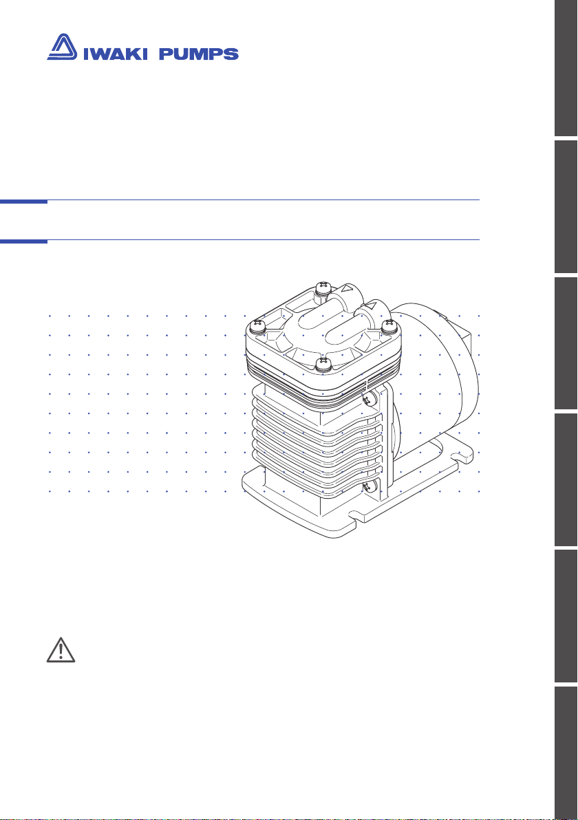
Iwaki Air Pump
APN-110
Safety instructions
Overview Installation Operation Maintenance Specication
Instruction manual
Thank you for choosing our product.
Please read through this instruction manual before use.
This instruction manual describes important precautions and
instructions for the product. Always keep it on hand for quick
reference.
© 2010 IWAKI CO.,LTD.
Page 2

Order conrmation
Open the package and check that the product conforms to your order. If
any problem or inconsistency is found, immediately contact your distributor.
a. Check if the delivery is correct.
Check the nameplate to see if the
information such as model codes,
discharge capacity and discharge
pressure are as ordered.
b. Check if the delivery is damaged or deformed.
Check for transit damage and loose bolts.
2
Order conrmation
Page 3

Contents
Order conrmation ............................................................................................. 2
Safety instructions .......................................................................5
WARNING .......................................................................................................... 6
CAUTION ...........................................................................................................7
Precautions for use ......................................................................................... 9
Overview ......................................................................................12
Introduction .....................................................................................................12
Pump structure & Operating principle .........................................................12
Part names.......................................................................................................13
Identication codes ........................................................................................14
Installation ..................................................................................15
Pump mounting ...............................................................................................15
Pipework ..........................................................................................................16
Tube connection ..........................................................................................16
Wiring ...............................................................................................................17
Power voltage/Earthing ...............................................................................17
Operation .....................................................................................18
Pump operation ..............................................................................................18
Operation .....................................................................................................18
Before a long period of stoppage (1 week or more) ....................................19
Contents
3
Page 4

Maintenance ................................................................................20
Troubleshooting ............................................................................................. 20
Inspection ....................................................................................................... 22
Daily inspection .......................................................................................... 22
Wear part replacement .................................................................................. 23
Wear part list ............................................................................................... 23
Before service ............................................................................................. 23
Diaphragm replacement ..............................................................................24
Valve replacement ...................................................................................... 25
Specication/Outer dimension .................................................................... 26
Specication ............................................................................................... 26
Pump ..................................................................................................... 26
Motor .....................................................................................................26
Outer dimension ......................................................................................... 27
APN-110 ................................................................................................ 27
APN-P110 .............................................................................................. 28
APN-S110 .............................................................................................. 28
Performance curves ................................................................................... 29
APN-110 ................................................................................................ 29
APN-P110 .............................................................................................. 29
APN-S110 .............................................................................................. 29
Part names & Structure .............................................................................. 30
APN-110 ................................................................................................ 30
APN-P110 ...............................................................................................31
APN-S110 .............................................................................................. 32
4
Contents
Page 5
Safety instructions
Requirement
Read through this section before use. This section describes
important information for you to prevent personal injury or
property damage.
■ Symbols
In this instruction manual, the degree of risk caused by incorrect use is noted
with the following symbols. Please pay attention to the information associated
with the symbols.
I
WARNING
CAUTION
A symbol accompanies each precaution, suggesting the use of "Caution", "Pro-
hibited actions" or specic "Requirements".
ndicates mishandling could lead to a fatal or
serious accident.
I
ndicates mishandling could lead to personal
injury or property damage.
Technical information contained in this instruction manual might be treated
as controlled technology in your countries, due to agreements in international
regime for export control.
Please be reminded that export license/permission could be required when this
manual is provided, due to export control regulations of your country.
Caution marks Prohibition marks Requirement marks
Caution
Electrical
shock
Prohibited
Do not rework
or alter
Wear
protection
Grounding
Export Restrictions
Safety instructions
5
Page 6
WARNING
Turn off power before service
Risk of electrical shock. Be sure to turn off power to stop the pump
and related devices before service is performed.
Stop operation
If you notice any abnormal or dangerous conditions, suspend op-
eration immediately and inspect/solve problems.
Do not use the pump in any condition other than its intended
purpose
The use of the pump in any conditions other than those clearly
specied may result in failure or injury. Use this product in a speci-
ed conditions only.
Do not modify the pump
Alterations to the pump carries a high degree of risk. It is not the
manufacturer's responsibility for any failure or injury resulting from
alternations to the pump.
Electrical
shock
Requirement
Prohibited
Do not remodel
Use specied power only
Do not apply power other than that specied on the nameplate.
Otherwise, failure or re may result. Ensure the pump is properly
grounded.
Wear protective clothing
Always wear protective clothing such as an eye protection, chemi-
cal resistant gloves, a mask and a face shield during disassembly,
assembly or maintenance work. The specic solution will dictate the
degree of protection. Refer to MSDS precautions from the solution
supplier.
Do not damage a power cable
Do not pull, knot or crush the power cable. Damage to the power
cable could lead to a re or electrical shock if cut or broken.
6
WARNING
Requirement
Wear
protectors
Prohibited
Page 7
CAUTION
Qualied personnel only
The pump should be handled or operated by qualied personnel
with a full understanding of the pump. Any person not familiar with
the product should not take part in the operation or maintenance of
the pump.
Keep electric parts and wiring dry
Risk of re or electric shock. Install the pump where it can be kept dry.
Ventilation
Fumes or vapours can be hazardous with certain solutions. Ensure
proper ventilation at the operation site.
Do not install/store the pump:
• In a ammable atmosphere.
• In a dusty/humid environment.
• Where operating (or storage) temperature can fall below 5ºC (or
0ºC) or exceed 40ºC.
Safety instructions
Requirement
Prohibited
Caution
Prohibited
Spill precautions
Ensure protection and containment of solution in the event of
plumbing or pump damage (secondary containment).
Do not use the pump in a wet location
The pump is not waterproof. Use of the pump in wet or extremely
humid locations could lead to electric shock or short circuit.
Grounding
Risk of electrical shock! Always properly ground the pump. Con-
form to local electric codes.
Requirement
Prohibited
Grounding
CAUTION
7
Page 8
Do no use a damaged power cable
Risk of fire or electric shock. The cable is not replaceable. The
whole pump unit needs to be replaced when the cable is damaged.
Install a GFCI (earth leakage breaker)
An electrical failure of the pump may adversely affect other de-
vices on the same line. Purchase and install a GFCI (earth leakage
breaker) separately.
Preventative maintenance
Follow instructions in this manual for replacement of wear parts. Do
not disassemble the pump beyond the extent of the instructions.
Do not use a damaged pump
Use of a damaged pump could lead to an electric shock or death.
Disposal of a used pump
Dispose of any used or damaged pump in accordance with local
rules and regulations. If necessary, consult a licensed industrial
waste disposal company.
Electrical
shock
Electrical
shock
Requirement
Prohibited
Requirement
8
CAUTION
Page 9

Precautions for use
• Electrical work should be performed by a qualied
electrician. Otherwise, personal injury or property
damage may result.
• Do not install the pump in a place where the pump
can get wet. Avoid using wet gas, or internal con-
densation will build up and consequently result in
the short lives of the valve and diaphragm.
• Do not use the pump in a dusty place. Be sure
to provide the inlet with a filter to prevent foreign
matters from getting into the pump. Otherwise, the
pump performance may reduce or the lives of the
valve and diaphragm remarkably shorten.
Safety instructions
Caution
• Do not install the pump in a corrosive or flamma-
ble gas atmosphere. Keep good ventilation in a
working area. Ambient temperature should not fall
below 5°C or exceed 40°C. Observe the allowable
gas temperature range of 0 and 40°C.
• If the compressed air (higher pressure than atmos-
pheric pressure) is transferred to the pump, sharp
deterioration to the lives of the valve, diaphragm
and bearing may result. Always keep atmospheric
or lower pressure in the suction line.
Do not increase suc-
tion line pressure
Precautions for use
9
Page 10
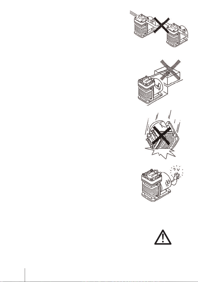
• Do not tube two or more pumps in series. It may
prevent the motor from starting and lead to a burn
out.
• Injection point must be below the pump position.
Or siphon action or back flow may result.
• Use care handling the pump. Do not drop. An
impact may affect pump performance. Do not use
a pump that has been damaged to avoid the risk of
electrical damage or shock.
• Do not apply power other than that specified on
the nameplate. Otherwise, failure or fire may
result.
• The pump can not start with full discharge/suc-
tion pressure. Remove pressure before operation.
After a long period of stoppage, pump performance at the beginning of operation becomes occa-
sionally unstable. In this case, warm the pump up
for 10 minutes with no discharge line pressure.
10
Precautions for use
Caution
Page 11
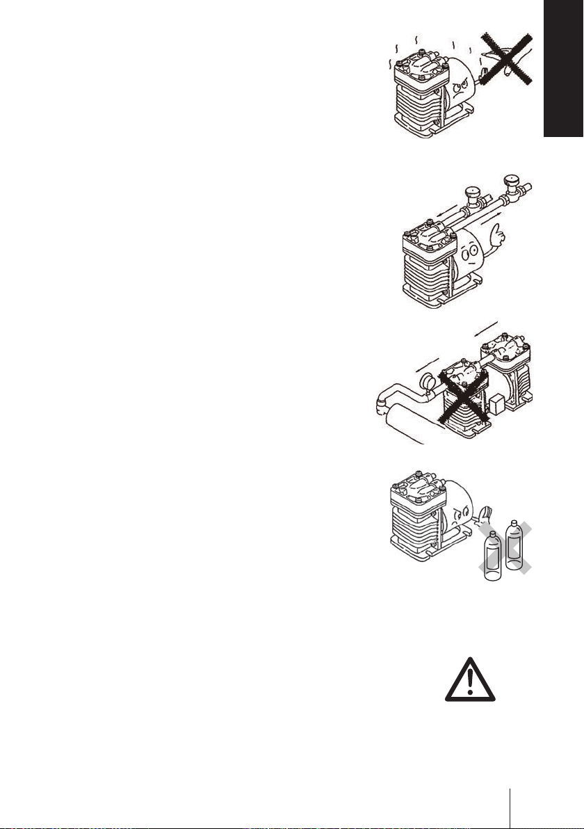
• Risk of burning. A pump and a pipe surface tem-
perature rises high along with liquid temperature.
Do not touch the pump or pipe surface directly
during operation or right after operation.
Safety instructions
• Always use a suction valve to adjust an air flow.
• The APN-S110 is designed for vacuum application
only. Do not pressurize the discharge line of the
pump.
• Do not clean the pump or nameplate with a solvent
such as benzine, thinner or kerosene. This may
discolour the pump or erase printing. Use a dry or
damp cloth or a neutral detergent.
Suction valve
Benzine
Thinner
• When an earth leakage breaker is used and it has
blown, always solve the root cause of blowout. Be
sure to unplug the power cable before investiga-
tion.
Caution
Precautions for use
11
Page 12

Overview
Pump characteristics, features and part names are described
in this section.
Introduction
Pump structure & Operating principle
The APN-110 is a diaphragm type air pump with a AC motor.
The rotary motion of the motor is converted through a connecting rod to the
reciprocation of the diaphragm in the pump chamber, where gas is transferred
from the inlet to outlet.
Outlet Inlet
Suction process
Connecting rod
Outlet Inlet
Diaphragm
: Gas flow
: Diaphragm reciprocation
Discharge process
12
Introduction
Page 13

Part names
Pump head
Not capable of liquid transfer. Air
transfer purpose only.
Overview
Inlet
Outlet
Specification label
Use the pump according to the specifica-
tions on the label.
Pump body (with a
built-in drive unit)
Base
Always fix with screws.
Part names
13
Page 14

Identication codes
The model code represents the following information.
APN - S 110 K V X - 1 - 02
a b c d e f g
a. Pump head
No code : Single head
S : Dual-head with series tubing
P : Dual-head with parallel tubing
b. Pump size
c. Inlet/outlet
K : Parallel type
L : In-line type
d. Diaphragm/Valve materials
V : FKM
E : EPDM
e. Pump connection
No code : ø8 tube connection
X : Rc1/4 female thread connection
X1 : G1/4 female thread connection
f. Power voltage
1 : 100VAC
2 : 200VAC
3 : 115VAC
4 : 220/240VAC
E4 : 220/240VAC (3-core cabtyre cable)
g. Special specication
14
Identication codes
Page 15

Installation
This section describes the installation of the pump, tubing and
wiring. Read through this section before work.
Observe the following points
• Risk of electrical shock. Be sure to turn off power to stop the pump and
related devices before service is performed.
• If you notice any abnormal or dangerous conditions, suspend operation
immediately and inspect/solve problems.
• Do not operate the pump in a ammable atmosphere.
Pump mounting
Select a suitable place.
1
See the Precautions for use section before installation.
Anchor the pump.
2
Use suitable bolts or screws.
Installation
NOTE
Do not install the pump on an unstable place.
Pump mounting
15
Page 16

Pipework
Connect tubes to the pump.
Before operation
• Cut the tube ends at.
Tube end (Side view)
Tube connection
a. The short tubing with the minimum bends is optimal to reduce resist-
ance.
b. Use vinyl tubes resistant to the pumping pressure.
Tube I.D. should be equal to the O.D. of the pump
inlet/outlet for the prevention of gas ingress/leak or
other failure.
* Do not have tubing bent or pressed. Otherwise, the tube
end may break.
Connect tubes into the inlet and outlet.
1
Push the tubes into the inlet and outlet as far
as they will go.
* If suction line connection is imperfect, the pump
entrains air and it prevents the pump from bringing
out full performance.
Inlet
Outlet
Valve mounting
2
Install a valve in the suction line for adjusting an air ow.
16
Pipework
Page 17

Wiring
Wiring for power source and earthing.
Observe the following points
• Electrical work should be performed by a qualied electrician. Conform
to local electric codes.
• Do not apply power other than that specified on the nameplate. Other-
wise, failure or fire may result.
• Do not perform wiring work while power is on. Otherwise, an electrical
shock or short circuit may result, and consequently the pump may fail. Be
sure to turn off power before service is performed.
• Be careful for electric power not to be turned on during work.
Power voltage/Earthing
Check that the main power is turned off.
Connect power cable via crimp contacts.
1
Installation
Earth the pump.
2
Be sure to earth the pump.
Wiring
17
Page 18

Operation
The pump becomes ready after pipework and wiring is completed.
Pump operation
Before operation
a. Check that the pump is firmly fixed on a mounting position.
b. Check that a suction tube is connected to the inlet and a discharge tube
is connected to the outlet.
* If a suction line and a discharge line are connected the other way around,
pumping process is inverted.
c. Check that every tube connection is secured.
d. Check that electrical wiring is properly done without the possibility of
short-circuit and protected by an fuse.
e. Check that power voltage that is specified on the nameplate is applied
to the pump.
Operation
Open the suction and discharge lines.
1
Turn on power.
2
Operation may occasionally be upset when starting temperature is low.
Warm up the pump under no load operation (a few minutes).
18
Pump operation
Page 19

3
After the pump has reached a specied stroke rate, initiate full
scale operation.
• Always adjust an air ow by a suction valve.
• In case electric power has failed while the pump is running, switch
off main power. Otherwise, the motor may not restart or may burn out
depending on a line pressure at the time of power recovery.
After starting, check a pressure gauge to see if suction and dis-
4
charge line pressure are correct and an air ow meter to see if the
specied air ow is obtained.
Before a long period of stoppage (1 week or more)
Release pressure from the pump/tubing and turn off the main power. Keep the
inside of the pump head free from residual gas.
Do not store the pump:
• In a flammable/corrosive atmosphere.
• In a dusty/humid environment.
• In direct sunlight or wind & rain.
• Under vibration.
• Where ambient temperature can exceed 0-40°C.
Operation
Pump operation
19
Page 20

Maintenance
This section describes troubleshooting, inspection, wear part
replacement, exploded views and specications.
Observe the following points
• Follow instructions in this manual for replacement of wear parts. Do not
disassemble the pump beyond the extent of the instructions.
• Always wear protective clothing such as an eye protection, chemical
resistant gloves, a mask and a face shield during disassembly, assembly
or maintenance work.
• Risk of electrical shock. Be sure to turn off power to stop the pump and
related devices before service is performed.
Troubleshooting
If you notice any abnormal or dangerous conditions, suspend operation immediately and check the following points. If the following measures do not help
remove problems, contact your nearest distributor.
States Possible causes Solutions
The pump
does not
run.
20
Troubleshooting
Power voltage is too low. • Observe the allowable voltage
The pump is not powered. • Check the pump is switched on if
Wrong tubing or poor connection • Check and x tubing.
Diaphragm xing screw is loose. • Tighten the screw.
Eccentric shaft has worn. • Replace the connecting rod unit.
Connecting rod bearing has worn. • Replace the connecting rod unit.
Motor trouble (a breaking wire, ca-
pacitor failure or bearing damage)
Suction line pressure is compressed and is higher than atmos-
pheric pressure.
range.
any.
• Correct wiring.
• Replace a breaking wire to new one.
Contact us.
Contact us.
• Replace the motor. Contact us.
• Keep it lower than atmospheric
pressure.
Page 21

Pump
operation
unintention-
ally stops.
Power voltage is too low. • Observe the allowable voltage
Suction line pressure is higher than
atmospheric pressure.
range.
• Keep it lower than atmospheric
pressure.
An air ow
rate and a
discharge
pressure are
too low.
Signicant
noise
Discharge line pressure is higher
than the maximum.
Connecting rod bearing has worn. • Replace the connecting rod unit.
Motor trouble (a breaking wire, ca-
pacitor failure or bearing damage)
Wrong tubing or poor connection • Check and x tubing.
Pump head mounting screws are
loose.
Diaphragm xing screw is loose. • Tighten the screw.
Diaphragm is broken. • Replace the diaphragm.
Filter is clogged. • Clean the lter.
Valve has worn. • Replace the valve.
Front cover xing screws are loose. • Tighten the screws.
Power voltage is too low. • Observe the allowable voltage
Pump head mounting screws are
loose.
Diaphragm xing screw is loose. • Tighten the screw.
• Observe the maximum discharge
pressure.
• For the APN-S type, its outlet
must be open to atmosphere.
Contact us.
• Replace the motor. Contact us.
• Tighten the screws.
range.
• Tighten the screws.
Diaphragm is broken. • Replace the diaphragm.
Front cover xing screws are loose. • Tighten the screws.
Eccentric shaft has worn. • Replace the connecting rod unit.
Contact us.
Connecting rod bearing has worn. • Replace the connecting rod unit.
Contact us.
Motor trouble (bearing damage) • Replace the motor. Contact us.
Troubleshooting
Maintenance
21
Page 22

Inspection
Perform daily and periodic inspections to keep pump performance and safety.
Daily inspection
Check the following points every day. If you notice any abnormal or dangerous
conditions, suspend operation immediately and remove problems according to
"Troubleshooting".
When wear parts come to the life limit, replace them by new ones. Contact
your distributor for detail.
No. States Points to be checked
1 Pumping • If the specied power voltage & starting current are
observed.
• If the suction and discharge pressure are normal.
2 Noise and vibration • If abnormal noise or vibration occurs. They are signs
of abnormal operation.
3 Gas ingress/leak from
pump head joints and a
suction line
• Check lines for a leak and retighten as necessary.
22
Inspection
Page 23

Wear part replacement
To run the pump for a long period, wear parts need to be replaced periodically.
It is recommended that the following parts are always stocked for immediate
replacement. Contact your nearest distributor for detail.
Wear part list
If pump performance has remarkably reduced, replace diaphragms and valves
with new ones.
Application
APN-110
8000hr 8000hrAPN-P110
APN-S110
* Wear part duration varies with the pressure, temperature and characteristics of gas.
* The estimated life above is calculated based on continuous operation at the rated volt-
age, 20°C ambient temperature at 20°C gas.
* The estimated life above changes with operating conditions and is not warranted.
Estimated life
Valve Diaphragm
Before service
Depressurize the pump system before service.
Turn off power to stop the pump.
1
Open both the suction- and discharge-line valves or remove the
2
pump from tubing system.
Maintenance
Wear part replacement
23
Page 24

Diaphragm replacement
Unscrew all the pump head xing
1
screws.
Take out the pump head, valve and valve
seat.
Pump head
fixing screw
Pump head
Valve
Remove the diaphragm xing screw
2
and detach the retainer plate and dia-
phragm.
Place a new diaphragm and the retain-
3
er plate onto the under retainer plate.
Secure the retainer plate and dia-
4
phragm.
Apply the LOCTITE
phragm xing screw and tighten it by
1.96N•m.
Push down the diaphragm until it bottoms out.
5
Mount and secure the valve seat, valve and pump head onto the bracket
with the screws by 1.96N•m.
®
222 to the dia-
Valve seat
Diaphragm
fixing screw
Retainer plate
Diaphragm
Under
retainer plate
Connecting rod
Bracket
Mating
point
APN-P110
24
Wear part replacement
Page 25

Valve replacement
Unscrew the pump head xing screws.
1
Take out the pump head, valve and valve seat. See page 24 for detail.
Replace the old valve with new one.
2
Always check the mating points and t
the valve and the pump head in place.
Retainer plate
Supply air into the pump head unit.
3
Check the air ows from the inlet to the outlet.
Push down the diaphragm until it bottoms out.
4
Secure the pump head unit onto the bracket with the xing screws by
1.96N•m.
Outlet
Pump head
Inlet
Valve
Valve seat
NOTE
• Do not loosen the bracket-motor fixing screws during maintenance work.
• Contact your nearest distributor for the replacement of the connecting rod, eccentric
shaft and the motor.
Wear part replacement
Maintenance
25
Page 26

Specication/Outer dimension
Specication
Information in this section is subject to change without notice.
■ Pump 50/60Hz
Model code
APN-110 KV/LV
APN-110 KE/LE
APN-P110 KV/LV
APN-P110 KE/LE
APN-S110 LV
APN-S110 LE
Max air
ow
12/14
L/min
24/28
L/min
12/14
L/min
Max
discharge
pressure
0.10
MPa
-
Max
vacuum
24.00
kPa
8.00
kPa
Connection
Tube Thread
ø8×ø5 Rc1/4
Weight
2.5kg
3.8kg
■ Motor
Model code
APN-110 KV/LV
APN-110 KE/LE
APN-P110 KV/LV
APN-P110 KE/LE
APN-S110 LV
APN-S110 LE
100V 115V 200V 220/240V
42/42W
(50/6 0Hz)
60/66W
(50/6 0Hz)
* Observe the maximum allowable discharge pressure of 0.1MPa (10kgf/cm²).
* The APN-S110 type is designed for vacuum application only with an open-ended dis-
charge line.
* Allowable gas temperature range is 0- 40ºC.
* Allowable ambient temper range is 5- 40ºC.
* The max air flow, discharge pressure and vacuum are based on the operation with
ambient air of 20ºC and may change with gas/room temperature.
* Allowable maximum noise level is 50dB at 1m (A scale).
Input power Output power Power current
44W
(60 Hz)
60W
(60 Hz)
44/44W
(50/6 0Hz)
66/ 74W
(50/6 0Hz)
48W
(50 Hz)
66W
(50 Hz)
100/115/200
/220/240V
10W
25W
100V 115V 200V 220/240V
0.50/0.44A
(50/6 0Hz)
0.76/0.70A
(50/6 0Hz)
0.42A
(60 Hz)
0.64A
(60 Hz)
0.25/0.22A
(50/6 0Hz)
0.40/0.41A
(50/6 0Hz)
Lowest
starting
temp.
5ºC
0.23A
(50 Hz)
0.36A
(50 Hz)
26
Specication/Outer dimension
Page 27

Model
Parts
Pump head GFRPP
Diaphragm
Reed valve
Valve seat GFRPP
Retainer plate GFRPPS
Screw Stainless steel
GFRPP : Glass fiber reinforced polypropylene
FKM : Fluorine-contained rubber
EPDM : Ethylene propylene diene monomer
GFRPPS : Glass fiber reinforced polypropylene sulfide
K V/LV KE/LE
FKM EPDM
Outer dimension
■ APN-110 mm
Specication/Outer dimension
Specication
27
Page 28

■ APN-P110 mm
■ APN-S110 mm
Specication/Outer dimension
28
Page 29

Performance curves
Vacuum 74.65kPa [abs]
Discharge pressure
Vacuum pressure
Vacuum 74.65kPa [abs]
Discharge pressure
■ APN-110
(MPa)
Vacuum pressure
(kPa) [abs]
■ APN-P110
(MPa)
Vacuum 87.98kPa [abs]
Vacuum 101.3kPa [abs]
AIR FLOW
(L/min)
Discharge pressure 0MPa
Vacuum 87.98kPa [abs]
Vacuum 101.3kPa [abs]
Vacuum pressure
■ APN-S110
(kPa) [abs]
(kPa) [abs]
AIR FLOW
(L/min)
Discharge pressure 0MPa
AIR FLOW
(L/min)
Discharge pressure 0MPa
Specication/Outer dimension
Specication
29
Page 30

Part names & Structure
■ APN-110
62
5
4
40
3
2
1
61
18
19
13
60
8
21 63
No. Part names Q'ty No. Part names Q'ty
1 Pump head 1 19 Connecting rod 1
2 Valve 1 21 Bracket 1
3 Valve seat 1 32 Con rod unit 1
4 Diaphragm 1 40 Motor 1
5 Retainer plate 1 60 Set screw 2
8 Eccentric shaft 1 61 Screw with washer 4
13 Bearing 1 62 Screw 1
18 Under retainer plate 1 63 Screw with washer 4
30
Specication/Outer dimension
Page 31

■ APN-P110
3
2
1
61
18
19
13
60
8
21 63
22
62
5
4
40
No. Part names Q'ty No. Part names Q'ty
1 Pump head 2 19 Connecting rod 2
2 Valve 2 22 Bracket 2
3 Valve seat 2 32 Con rod unit 2
4 Diaphragm 2 40 Motor 1
5 Retainer plate 2 60 Set screw 2
8 Eccentric shaft 2 61 Screw with washer 4
13 Bearing 2 62 Screw 2
18 Under retainer plate 2 63 Screw with washer 4
Specication/Outer dimension
Specication
31
Page 32

■ APN-S110
3
2
1
18
19
13
60
8
21 63
22 61 40
100
62
5
4
No. Part names Q'ty No. Part names Q'ty
1 Pump head 2 22 Bracket 2
2 Valve 2 32 Con rod unit 2
3 Valve seat 2 40 Motor 1
4 Diaphragm 2 60 Set screw 4
5 Retainer plate 2 61 Screw with washer 8
8 Eccentric shaft 2 62 Screw 2
13 Bearing 2 63 Screw with washer 8
18 Under retainer plate 2 100 Hose 1
19 Connecting rod 2
Specication/Outer dimension
32
Page 33

Specication
Specication/Outer dimension
33
Page 34

34
Page 35

35
Page 36

Australia IWAKI Pumps Australia Pty. Ltd.
Austria IWAKI EUROPE GmbH
Belgium IWAKI Belgium n.v.
China IWAKI Pumps (Shanghai) Co., Ltd.
China IWAKI Pumps (Guangdong) Co., Ltd.
China
GFTZ IWAKI Engineering & T rading (Guangzhou)
China
GFTZ IWAKI Engineering & T rading (Beijing)
Denmark IWAKI Nordic A/S
Finland IWAKI Suomi Oy
France IWAKI France S.A.
Germany IWAKI EUROPE GmbH
Holland
IWAKI Europe GmbH, Netherlands Branch
Hong Kong IWAKI Pumps Co., Ltd.
Indonesia
IWAKI Singapore (Indonesia Branch)
( )Country codes
IWAKI CO.,LTD. 6-6 Kanda-Sudacho 2-chome Chiyoda-ku Tokyo 101-8558 Japan
TEL:(81)3 3254 2935 FAX:3 3252 8892(http://www.iwakipumps.jp)
Italy
TEL : (61)2 9899 2411 FAX : 2 9899 2421
TEL : (49)2154 9254 0 FAX : 2154 9254 48
TEL : (32)1367 0200 FAX : 1367 2030
TEL : (86)21 6272 7502 FAX : 21 6272 6929
TEL : (86)750 3866228 FAX : 750 3866278
TEL : (86)20 8435 0603 FAX : 20 8435 9181
TEL : (86)10 6442 7713 FAX : 10 6442 7712
TEL : (45)48 24 2345 FAX : 48 24 2346
TEL : (358)9 2745810 FAX : 9 2742715
TEL : (33)1 69 63 33 70 FAX : 1 64 49 92 73
TEL : (49)2154 9254 0 FAX : 2154 9254 48
TEL : (31)74 2420011 FAX : 2154 9254 48
TEL : (852)2 607 1168 FAX : 2 607 1000
TEL : (62)21 690 6606 FAX : 21 690 6612
IWAKI Europe GmbH, Italy Branch TEL : (39)0444 371115 FAX : 0444 335350
Korea IWAKI Korea Co.,Ltd.
Malaysia IWAKIm Sdn. Bhd.
Norway IWAKI Norge AS
Singapore IWAKI Singapore Pte. Ltd.
Spain
IWAKI Europe GmbH, Spain Branch
Sweden IWAKI Sverige AB
Switzerland IP Service SA
Taiwan IWAKI Pumps Taiwan Co., Ltd.
Taiwan
IWAKI Pumps Taiwan (Hsin-chu) Co., Ltd. TEL : (886)3 573 5797
Thailand IWAKI (Thailand) Co.,Ltd.
U.K. IWAKI Pumps (UK) LTD.
U.S.A. IWAKI AMERICA Inc
Vietnam IWAKI Pumps Vietnam Co.,Ltd.
TEL : (82)2 2630 4800 FAX : 2 2630 4801
TEL : (60)3 7803 8807 F AX : 3 7803 4800
TEL : (47)23 38 49 00 FAX : 23 38 49 01
TEL : (65)6316 2028 FAX : 6316 3221
TEL : (34)93 37 70 198 FAX : 93 47 40 991
TEL : (46)8 511 72900 F AX : 8 511 72922
TEL : (41)26 674 9300 FAX : 26 674 9302
TEL : (886)2 8227 6900
TEL : (66)2 322 2471 FAX : 2 322 2477
TEL : (44)1743 231363 FAX : 1743 366507
TEL : (1)508 429 1440 F AX : 508 429 1386
TEL : (84)613 933456 FAX : 613 933399
FAX : 2 8227 6818
FAX : (886)3 573 5798
T814-2 '15/03
 Loading...