

IWAKI AMERICA WMD-100 Series, WMD-100R, WMD-100F, WMD-100RT, WMD-100FY Instruction Manual
...
IWAKI AMERICA
MAGNETIC DRIVE PUMP
WMD-100 SERIES
INSTRUCTION MANUAL

Thank you for having selected an Iwaki America WMD-100 Series magnetic drive pump. This
instruction manual deals with the correct handling, maintenance, inspection, and troubleshooting
procedures for the WMD-100 magnetic drive pump. Please read through it carefully to ensure
the optimum performance, safety and long service of your pump.
Contents
Item Page
1 Unpacking and Inspection.........................................................................................1
2 Identification.............................................................................................................1
3 Specifications............................................................................................................2
4 Handling...................................................................................................................2
5 Installation and Operation..........................................................................................3
6 Assembly..................................................................................................................4
7 Maintenance and Inspection......................................................................................5
8 Parts Description and Exploded View........................................................................6
9 External Dimensions and Weight...............................................................................7
P/N 180184.E 11/28/05
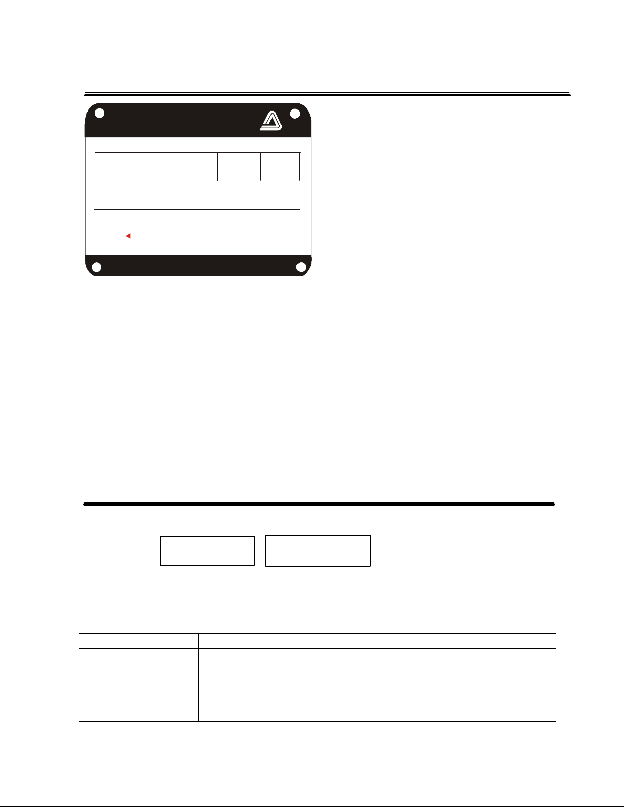
1 Unpacking and Inspection
CAPACITY (GPM)
IMPELLER DIAMETER
HOLLISTON, MASSACHUSETTS
DIRECTION OF ROTATION
Iwaki
Mag-Drive Pump
MODEL
HEAD (FT.)
SERIAL NO.
WMD-100
HP
DO NOT RUN PUMP DRY
www.iwakiwalchem.com
Hz.
RPM
Open the package and check that the product
conforms to your order. Also, check each of the
following points. For any problem or
inconsistency, contact your distributor at once.
1. Check that the model number indicated on the
nameplate conforms to the specifications of
your order.
2. Check that all the accessories you ordered are
included.
3. Check that the pump body and parts have not
been accidentally damaged or that any bolts
have not been loosened in transit.
2 Model Identification Guide
1 2
WMD-100 R RT F
1. Series name
2. Materials of construction
R RT F
Materials Glass fiber reinforced polypropylene
Connections Hose 1" I.D. conn. 1" NPT male
Bearings Alumina Ceramic/Rulon Silicon Carbide
O-ring FKM (Viton)
(GFRPP)
1
Carbon fiber reinforced
fluoroplastic

3 Specifications
WMD-100R(T) WMD-100FY WMD-100FZ
Specific gravity limit 1.2 1.3* 1.9*
Max capacity gpm (L/min) 36 (136) 36 (136) 28 (106)
Max head ft (m) 41.5 (12.6) 38 (11.6) 27 (8)
Motor output hp (kw) 1/3 (.25)
Notes:
1. Fluid temperature range: 32-176°F (0-80°C)
2. *Limit of specific gravity at maximum flow when fluid viscosity is 1 CP. Specific gravity fluids up
to 2.2 can be handled with appropriate trimming of impeller. Consult factory for recommended trim.
4 Handling Instructions
1. Do not operate the pump dry.
The sliding parts used in the WMD-100 series pump are lubricated and cooled by the fluid being
pumped. Never operate the pump dry or with the valves on the suction side closed. Otherwise, the
inside of the pump will be damaged. If the pump is unavoidably or accidentally operated dry, with
no obvious damage, allow the pump to cool down for a minimum of one hour before attempting to
restart. Do not allow fluid to enter the pump cavity until the pump has cooled down. Sudden or
rapid cooling of the pump may cause damage to the bearing system. A dry run operation device is
recommended for the prevention of dry pump operation.
2. Starting
Prior to starting the pump, make sure that the power is turned off. Then carry out priming to fill the
pump cavity with liquid.
Next, close the valves on the discharge side. Now you can turn the power on and start up the pump.
When the pump has reached full speed and line pressure is stable, the discharge valves can be
opened to the desired settings.
3. Stopping
When stopping the pump, first close the discharge valve gradually. When it is completely closed,
turn off the power switch so that the pump stops. Never stop the pump suddenly by quickly closing
a valve (i.e., solenoid or hydraulic valves).
Caution
Quick valve closure may cause water hammer which can cause severe damage to the pump.
2
 Loading...