

IWAKI MX-70, MX-100 Instruction Manual
IWAKI Magnetic Drive Pump
MX-70/-100 (Asia Edition)
Instruction Manual
Read this manual before use of product
Thank you for selecting an Iwaki MX-70/-100 type Magnetic Drive
Pump. This instruction manual deals with "Safety Instructions",
"Outline", "Installation", "Operation" and "Maintenance" sections.
Please read through this instruction manual to ensure the optimum performance, safety and service of your pump.
Contents
Safety Instructions ·········································································· 1
Outline 1. Unpacking & Inspection ······································· 3
2. Operating principle ··············································· 3
3. Identification code ················································4
4. Specification ·························································4
5. Outer dimensions ·················································· 5
6. Performance curves ·············································6
7. Overview & Label ·················································6
8. Part names & Structure ········································7
Installation 1. Before installation ·················································9
2. Installation/Piping/Electrical wiring ················· 11
Operation 1. Before operation ·················································· 14
Maintenance 1. Troubleshooting ·················································· 16
2. Maintenance & Inspection ································· 16
3. Drainage ······························································ 17
This instruction manual should be kept on hand by the end user
for quick reference.
Contact us or your nearest dealer if you have any questions.
Important Instruction
For the Safe and
Correct Handling of the Pump
● "Safety Instruction" section deals with important details about
handling of the product. Before use, read this section carefully for
the prevention of personal injury or property damage.
● Observe the instructions accompanied with "WARNING" or
"CAUTION" in this manual. These instructions are very important for protecting pump users from dangerous situations.
● The symbols on this instruction manual have the following meanings:
Nonobservance or misapplication of the
WARNING
CAUTION
Indicates a prohibited action or procedure. Inside or near this circle, a concrete and practical image of the activity to be avoided is
depicted.
Indicates an impor tant action or procedure which must be performed or car ried out without fail. Failure to follow the instructions herein can lead to malfunction or damage to the pump.
For expor tation
Technology related to the use of goods in this instruction manual falls
in the category of technology contained in the Foreign Exchange
Order Attachment, which includes complementary export control of
technology. Please be reminded that export license, which is issued
by the Ministry of Economy, Trade, and Industry could be required,
when this is exported or provided to someone even in Japan.
contents of “Warning” section could lead to
a serious accident which may result in death.
Nonobservance or misapplication of the
contents of “Caution” section could lead to
a personal injury or damage to the product.
Types of Symbols
Power of f
Safety Instructions
Prohibited
Prohibited
Prohibited
No modif icati on
No dismantlement
Caution
Caution
Wear prote ctors
Prohibited
Prohibited
● Turn off the power.
Risk of electrical shock. Dismantling/
assembling the pump unit without turning off the power may cause an electrical
shock. Before engaging in any maintenance
or inspection work, be sure to turn off the
pump and related devices.
● Terminate operation.
On sensing any abnormal sign, stop operation immediately and inspect/solve problems.
● For specified application only
The use of the pump in any application
other than those clearly specified may result
in injury or damage. Use the pump in a
specified condition.
● No dismantlement/modification
Do not dismantle/modify the pump. We are
not responsible for any accidents or damage
due to modification.
● Wear protective clothing.
Always wear protective clothing such as
safety goggles and protective gloves during
pipework or dismantlement.
WARNING
CAUTION
● Restriction on operator
The pump should be handled by a qualified
person with a full understanding.
● Specified power only
Do not apply any power other than the specified one on the nameplate. Otherwise damage, a fire or an electrical shock may result.
● Do not wet the pump.
If a liquid spills over electric parts or wires, a
fire or electrical shock may result. Install the
pump in a place free from liquid spillage.
● Ventilation
Poisoning may result when handling a toxic
or odorous liquid. Keep good ventilation in
your operating site.
● Countermeasure against efflux
Take a protective measure against the accidental efflux caused by pump or pipe breakage.
● Do not use a damaged pump.
Using a damaged pump may lead to an
electric leak or shock.
- 1 -
Prohibited
Safety Instructions
Caution
Prohibited
Prohibited
Electrical shock
Prohibited
Earthing
Electrical shock
CAUTION CAUTION
● Do not place the pump close to water.
The pump is not dust-/water-proof construction. The use of the pump in a humid place
or a place where the pump can get wet may
result in electrical shock or short-circuit.
● Do not run pump dry.
If the pump runs without a liquid, the pump
is damaged by friction heat.
● Do not damage the power cable.
Risk of fire or electrical shock. Do not
scratch, modify, or pull the power cable.
The cable can also be damaged when it is
heated or loaded with a heavy thing.
● Earthing
Risk of electrical shock. Always earth the pump.
● Do not pressurize the pump over the
maximum discharge pressure.
A leak may result from the sealing surface
of O ring or the pump fails at worst.
● Install an earth leakage breaker.
An electrical failure of the pump may adversely affect related devices. Purchase and
install an earth leakage breaker separately.
● Power cable is not replaceable.
Do not use any damaged power cable
for the prevention of a fire or an electrical
shock. The cable is not replaceable, so that
the whole pump unit needs to be replaced
when the cable is damaged.
● Limited operating site and storage
Do not install or store the pump in the following places where...
1. Ambient is beyond the range of 0 - 40°C.
2. Under a flammable/corrosive atmosphere.
● Disposal of the used pump
Dispose of any used or damaged pump
in accordance with relevant regulations.
Consult a licensed industrial waste products
disposing company.
● Static electricity
When low electric conductivity liquids such
as ultra-pure water and fluor inactive liquid
(e.g. Fluorinert
TM
) are handled, static electricity may generate in the pump and may
cause static discharge. Take countermeasures to remove static electricity.
- 2 -
Outline
Before use, check the specification, limitation and hazardous
nature of the pump.
1. Unpacking & Inspection
On unpacking the product, check the following points. If
you find any problems, contact your nearest dealer.
1. Check the information on the nameplate such as model, discharge
capacity, discharge head and voltage to see that the product is delivered as per order.
2. Check for transit damage, deformation, and loose bolts.
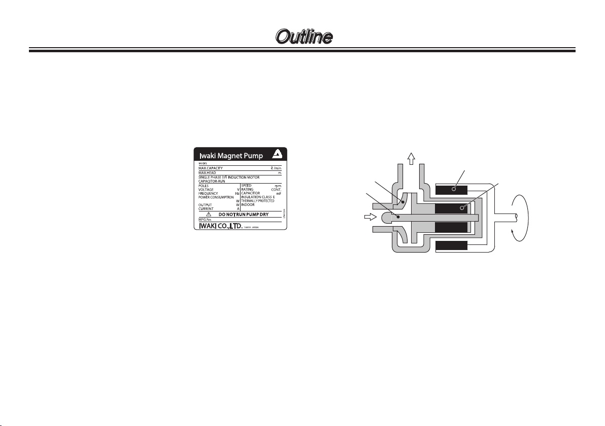
2. Operating principle
The MX is a magnetic drive centrifugal pump.
The magnetic force between drive and driven magnets
rotates the impeller in the pump chamber, where a liquid
is transferred from the inlet to outlet.
Outlet
Drive magnet
Impeller
Spindle
Inlet
Driven magnet
- 3 -
Outline
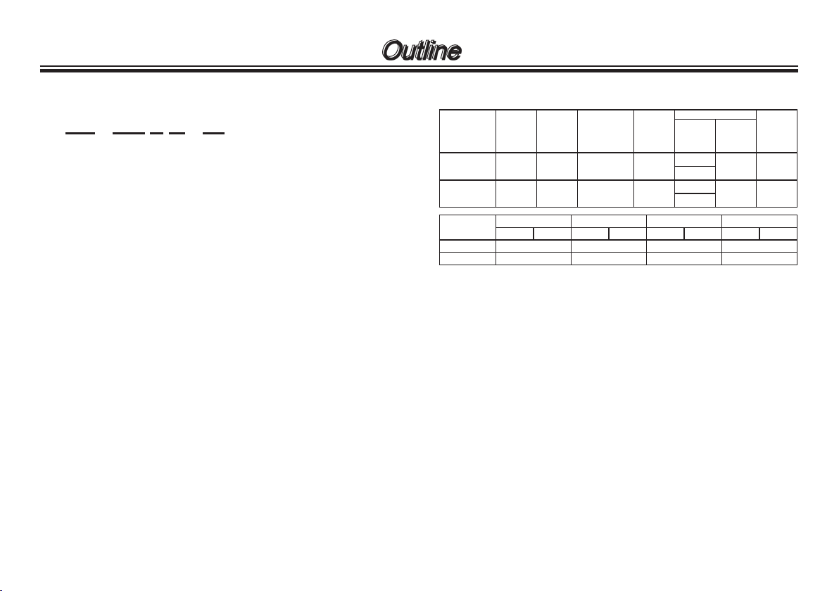
3. Identification code
MX - 100 V M - 32
a b c d e
a. Series model
GFRPP casing material
b. Pump size
70
100
c. O ring material
V: FKM
E: EPDM
d. Inlet/Outlet
No code: Tube connection
M : Thread type (G)
FL : Flange connection
e. Motor power voltage
No code: 1 phase 100V
32 : 3 phases 200/220V
4. Specification 50/60Hz
Model
MX-70 90/10 0 8/ 11 5.4-50/7.8-50 1.0
MX-1 00 110 /12 5 8.4/11.7 6-70/ 9-70 1. 2
Model
MX-70 26mm G1 20mm 25A
MX-1 00 26mm G1 20mm 25A
Max ow
(L/min)
Tube connec tion Thread connection Union connection Flange conne ction
Max
Norm ow
head
(m-L/min)
(m)
Inlet Outlet Inlet Outlet Inlet Outlet Inlet Outlet
Max SG
NOTE:
a. Performance data is based on pumping of clear water at
ambient temperature.
b. Allowable liquid temperature is 0-80°C (0-55°C for union
connection). Note that the temperature range may change
with liquid property. Avoid a precipitous fluctuation of temperature even in the liquid temperature range above.
c. The maximum head is a shutoff head. Note that shutoff oper-
ation is not allowed, or it may adversely affect a life period.
d. The maximum specific gravity is obtained at the normal flow
and changes with a duty point, room-/liquid-temperatures
and liquid viscosity.
e. A single-phase capacitor-start induction motor and a
3-phase motor are selectable.
f. See the specification label on the pump for detail info.
g. Performance and dimension are subject to change without
prior notice.
Power
(V)
100
200 or 2 20
100
200 or 2 20
Motor
Rated
output
(W)
150/180 6.5
260/260 8.2
Mass
(kg)
- 4 -
 Loading...