

IWAKI MDW Series, MDW50 MDW80, MDW100 Instruction Manual
Read this manual before use of product
IWAKI Magnetic Drive Pump
MDW Series
Instruction Manual

Thank you for selecting an Iwaki MDW Magnetic Drive Pump. This instruction manual deals
with "Safety instructions", "Outline", "Installation", "Operation" and "Maintenance" sec-
tions. Please read through this manual carefully to ensure the optimum performance, safety
and service of your pump.
Contents
Safety instructions ·········································································· 1
Outline 1. Unpacking & Inspection
..................................................
7
2. Product outline
.................................................................
7
3. Model code
.......................................................................
8
4. Overview
..........................................................................
9
5. Dimensions
.....................................................................
10
6. Precautions for use
.........................................................
11
Installation 1. Before installation
..........................................................
15
2. Pipework
........................................................................
16
3. Wiring
............................................................................
19
Operation 1. Before operation
.............................................................
21
2. Operation
........................................................................
22
3. Shutdown
........................................................................
23
Maintenance 1. Troubleshooting
..............................................................
25
2. Maintenance & Inspection
.............................................
26
3. Spare & Wear parts
........................................................
31
4. Assembly & Disassembly
..............................................
33
This instruction manual should be kept on hand by the end user for
quick reference.
Contact us or your nearest dealer if you have any questions.
- 1 -
Safety instructions
For exportation
Information contained within this instruction manual may be considered controlled technol-
ogy as set by the Japanese Ministry of Economy, Trade and Industry (METI). An export
license issued by METI may be required when exporting or providing the manual to a 3rd
party.
Nonobservance or misapplication of “Caution” sections could lead to personal injury or property damage.
For the Safe and
Correct Handling of the Pump
ŏ
"Safety Instruction" section deals with important details about handling of the product. Before
use, read this section carefully for the prevention of personal injury or property damage.
ŏ
Observe the instructions accompanied with "WARNING" or "CAUTION" in this manual. These
instructions are very important for protecting users from dangerous situations.
ŏ
The symbols on this instruction manual have the following meanings:
WARNING
Nonobservance or misapplication of “Warning” sections could lead to a serious accident which may
result in death.
CAUTION
Types of Symbols
Indicates that “Warning” or “Caution” must be exercised. Inside this triangle, a con-
crete and practical image provided as a warning or caution message is depicted.
Indicates a prohibited action or procedure. Inside or near this circle, a concrete and
practical image of the activity to be avoided is depicted.
Indicates an important action or procedure which must be performed or carried out
without fail. Failure to follow the instructions herein can lead to malfunction or
damage to the pump.
- 2 -
Ɣ Access limitation
The magnet drive pump has a pair of strong magnets (the magnet capsule
unit and drive magnet). The strong magnet field could adversely affect the
persons who are assisted by electronic devices such as the pacemaker.
Ɣ Turn off power before work
Be sure to turn off power to stop the pump and related devices before work.
Make sure no one turns on power by mistake while working on the pump,
otherwise it may result in a serious accident. If your working area is noisy or
dark, let other people know about the situation by displaying a notice such
as "POWER OFF (Maintenance)" near a power switch.
Ɣ Wear protective clothing
Always wear protective clothing such as eye protection and protective
gloves during pipework or dismantlement of the pump.
Ɣ Do not remodel the pump
Do not remodel the pump. We are not responsible for personal injury or
property damage due to any modification.
Ɣ When handling dangerous liquid
For the transfer of the harmful liquid as mentioned below, be sure to conduct
daily inspection and maintenance for the prevention of liquid/gas leakage.
1. Explosive or flammable liquid
2. Corrosive chemicals
3. Harmful liquid or gas
Ɣ Use strong ropes (chains) for lifting up the pump
Serious injury may result if lifting ropes (chains) break. Check lifting ropes
(chains) are strong enough before use.
Ɣ Lift the pump with eye bolts or lifting holes
Use an eye bolt when lifting the pump unit only. Use lifting holes on the base
if the pump unit is mounted on it. In this case do not use the eye bolts.
WARNING
Turning off p ower
Prohibited
Wear protective
gear
No Remodeling
Safety instructions
- 3 -
Ɣ Magnetic force affects magnetic disks/cards and wrist watches
A pair of strong magnets is mounted in the pump and its magnet force may affect
magnetic disks/cards or wrist watches. Do not bring them close to the pump.
Ɣ A qualified operator only
The pump must be handled or operated by a qualified person with a full
understanding of the pump.
Ɣ A specified application only
The use of the pump in any purpose other than those clearly specified may
result in personal injury or property damage. Use this product in a specified
condition.
Ɣ A specified power only
Risk of fire, electrical shock or pump failure. Do not apply any power other
than the one specified on the motor label.
Ɣ Keep good ventilation
Poisoning may result when handling a toxic or odorous liquid. Install an air
fan in order to reduce the possibility of health damage.
Ɣ Countermeasure against efflux
Take a protective measurement against an accidental chemical overflow
results from pump or piping breakage. Do not soak chemicals into the
ground directory.
Ɣ Do not run pump dry
Running the pump without liquid, friction heat damages the inside of pump.
Dry running takes place when starting the pump with a closed suction line
or without priming.
Ɣ Keep the pump away from a flammable substance
Otherwise, fire may result.
Ɣ When unpacking a wooden box
Be careful not to be injured by nails or sprinters.
CAUTION
Prohibited
Fire ban
Prohibited
Caution
Prohibited
Prohibited
Prohibited
Safety instructions
- 4 -
Ɣ Do not stand on the pump
Personal injury may result as the pump turns over.
Ɣ Do not touch the pump or pipe with bare hands
The surface temperature of the pump or pipe rises high along with liquid
temperature in or right after operation.
Ɣ Earth connection
Always earth the pump in order to reduce the risk of electrical shock.
Ɣ Install an earth leakage breaker
Risk of electrical shock. Do not use the pump without an earth leakage
breaker.
Ɣ Do not install or store the pump in the following places where...
1. Ambient temperature is beyond 0-40°C.
2. Ambient humidity is beyond 35-85%RH.
3. Under a flammable or an explosive atmosphere or in a dusty place.
4. Under wind and rain.
5. Under vibration.
6. Under a corrosive atmosphere such as chlorine gas.
Ɣ Remove foreign matters
Turn off power as soon as foreign matters enter the pump in order to
remove them. Otherwise, the pump may be damaged.
Ɣ Disposal of the used pump
Dispose of a used pump in accordance with local laws and regulations
(Consult a licensed industrial waste products disposing company.).
Ɣ Do not drop the pump down
The pump itself and its individual parts are heavy due to its largeness.
Personal injury may result when one of them falls down. Keep a work space
wide enough and use necessary equipment for secure your safety.
Prohibited
Grounding
Prohibited
Prohibited
Caution
CAUTION
Safety instructions

- 5 -
Ɣ Do not touch a rotating part
A pump shaft and a motor shaft may be coupled barely. Be sure to cover the
coupling in order to reduce the risk of personal injury which may occur as
coming in contact with the coupling in operation.
Ɣ Take countermeasures against static electricity
When low electric conductivity liquids such as ultra-pure water and fluor
inactive liquid (e.g. Fluorinert
TM
) are handled, static electricity may be gener-
ated in the pump and may cause static discharge.
Ɣ Conduct degassing before load operation
Always prime the pump and remove air before operation. Make sure that air
is completely expelled from both a discharge and a suction line. Especially,
the air in a suction line can cause dry running and damage sliding parts
when it enters the pump at once. Note that hydrogen peroxide and sodium
hypochlorite easily generate gas and degassing is needed frequently.
Ɣ Do not incinerate plastic parts
Fluoroplastic parts are used in this product. Throwing fluoroplastics into the
fire is accompanied with harmful gas. Dispose of fluoroplastics as an incom-
bustible.
Safety instructions
CAUTION

- 6 -
Outline
1. Unpacking & Inspection ........................ 7
2. Product outline ...................................... 7
3. Model code ........................................... 8
4. Overview ...............................................9
5. Dimensions ......................................... 10
6. Precautions for use ............................. 11
- 7 -
On unpacking the product, check the following
points. If you find any problems, contact your
nearest distributor.
1. Check the information on labels for model codes,
a flow rate, head & power voltage and the deliv-
ery is as per order.
2. Check if attachments are complete. Also, check
optional products.
<Attachment list>
a. Guide bolts (Two each)
b. Hexagon bolts (M12×130: Two each)
<Optional product list>
Spare parts or peripheral devices such as the
dry run protector.
3. Check for transit damage.
4. Check for loose bolts.
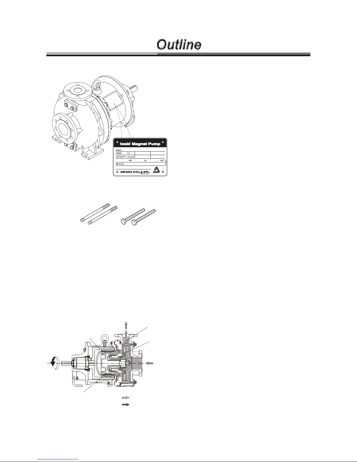
2. Product outline
An Iwaki magnetic drive pump, the MDW, is a long coupled pump. This large-scale process magnet
pump has fluoroplastic and fine ceramic wet ends and is capable of sending most chemicals includ-
ing strong acid and alkaline.
Ŷ Principle of operation
The long coupled motor unit rotates the driven
magnet in the pump unit.
An impeller rotates in the pump chamber along with
the driven magnet to transfer liquid from the inlet to
outlet.
Outline
1. Unpacking & Inspection
a. Guide bolts b. Hexagon bolts
Drive magnet
Outlet
Inlet
Impeller
Driven magnet
Pump chamber
: Flow direction
: Impeller rotation

- 8 -
3. Model code
MDW 50 - 260 P K Z C 450 J - E 2
a b c d e f g h i j k
a. Series name
MDW: A long coupled pump with a foot mounted motor
b. Pump bore size & Motor output
Model
Pump bore size
(Inlet × Outlet)
Motor output (kW)
Weight (kg)
2P 4P
MDW50 80A × 50A 22/30/37/45/55/75
11/15/18.5/22/37
155
MDW80 125A × 80A
37/45/55/75 170
MDW100 125A × 100A
c. Impeller nominal diameter
170 - 260
d. Wet end materials
E: ETFE + PFA P: PFA
e. Bearing/Thrust/Sleeve
K: SiC/SiC/SiC
f. O ring material
Z: Kalrez
®
g. Motor unit
C: Foot mounted motor
h. Motor output
110: 11kW, 150: 15kW, 185: 18.5kW, 220: 22kW, 300: 30kW
370: 37kW, 450: 45kW, 550: 55kW, 750: 75kW
i. Flange & Motor standard
I: ISO flange/ IEC motor
J: JIS flange/ JIS motor
A: ANSI flange/ JIS motor
j. Drain
Code Drain port/Air vent port Delivery state Standard/Special version
A
No drain port provided
No air vent port provided
A pump on a base
Standard
S Special version
D
A drain port provided
An air vent port provided
Standard
X Special version
B
No drain port provided
No air vent port provided
Pump unit
• No base
• No coupling
• No coupling cover
Standard
Y Special version
E
A drain port provided
An air vent port provided
Standard
Z Special version
k. Pole number
2: Two 4: Four
Outline
- 9 -
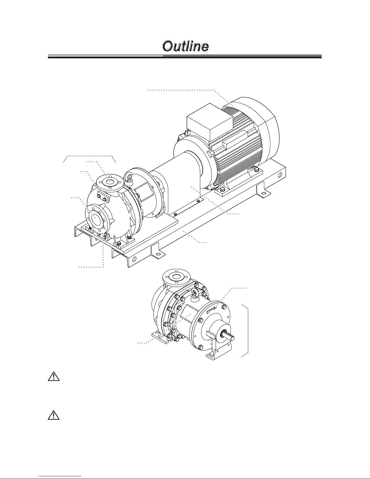
Pump label
Observe the specification
on the pump label.
Drain port
(Drain plate)
Provided as requested.
Note that liquid can not be
drained completely through
this port. Pay attention to
residual liquid.
Motor unit
Transfers torque to the pump
unit via a long coupling.
Observe the power voltage
specified on the motor label.
Rotational direction
The pump must rotate along
with the rotational direction.
Base
The pump on a base. The base is
provided if requested.
Always mount the pump on the base.
4. Overview
The illustration below shows a long coupled pump on the base.
Coupling cover
Covers the coupling. Do not put
the hand or finger into a joint gap.
Outline
Air vent por t
(Air vent plate)
Provided as
requested.
Pump unit
Outlet
Inlet
CAUTION
Wet a cloth with tap water and wring it out for cleaning the pump.
Use a neutral detergent for greasy dirt and then rub with a dry cloth. Do not wipe labels or
the pump body with any solvent.
CAUTION
Turn off main power before cleaning. Be careful not to wet the motor unit (terminal box and
fan cover) and wiring. Otherwise electrical shock or short circuit may result.
Pump unit
- 10 -
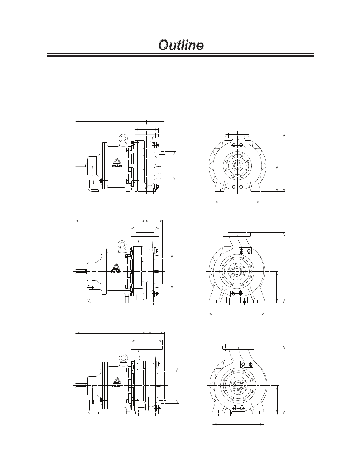
5. Dimensions
See an approved drawing for part names and structure.
Ŷ Pump unit
See the approval drawing for detail dimension.
MDW80
MDW100
500
125
ø165
ø200
(405)
180
320
500
125
ø200
ø250
(505)
225
400
500
125
ø220
ø250
(480)
200
360
MDW50
Outline
- 11 -
6. Precautions for use
Read through this section before operation.
CAUTION
Ɣ Do not run pump dry
Sliding parts always need liquid in the pump chamber for lubrication and cooling. Do not produce dry running or closed-discharge operation. The pump
unit will be damaged.
* If the pump runs dry by mistake, turn off power and leave it for more than
one hour to cool it down. Do not refill the pump chamber soon. Quick cooling
can give rise to cracks on parts.
Ɣ Be sure to prime the pump before operation
Always prime the pump when it is empty, for example, the pump is used for
the first time or after dismantlement/assembly. Running the pump without
priming water, internal parts are excessively worn by friction heat and fatal
pump damage results.
Ɣ A specified application only
Do not use the pump in anything other than a specified purpose. Observe the
specification described on the pump or motor label.
Ɣ A qualified operator only
The pump must be handled or operated by a qualified person with a full
understanding of the pump. Any person who is not familiar with this product
should not take part in the operation or management.
1. Use this pump for sending a liquid only
This pump is not capable of closed-discharge operation. Always keep the minimum flow.
Minimum flow
Model
Motor poles
2P 4P
MDW50 12m³/hr (200Ɛ/min) 12m³/hr (200Ɛ/min)
MDW80/100 60m³/hr (1000Ɛ/min) 12m³/hr (200Ɛ/min)
2. Observe the following conditions. Contact us or your nearest distributor for detail.
a. The pump is not capable of slurry and should not be used for it.
b. Maximum liquid viscosity: 120mPa•s Contact us before sending a liquid over 120mPa•s.
c. Liquid temperature range:
MDW50: -10 - 120°C
MDW80/100: -10 - 105°C
Allowable liquid temperature range varies with chemical liquid. Contact us when a liquid temperature is
at or below 0°C.
d. Ambient temperature: 0-40°C
e. Ambient humidity: 35-85%RH
*Before operation, see the specification sheet for pump performance.
Outline
Prohibited
Observe the freezing and boiling points of the chemical liquid.
- 12 -
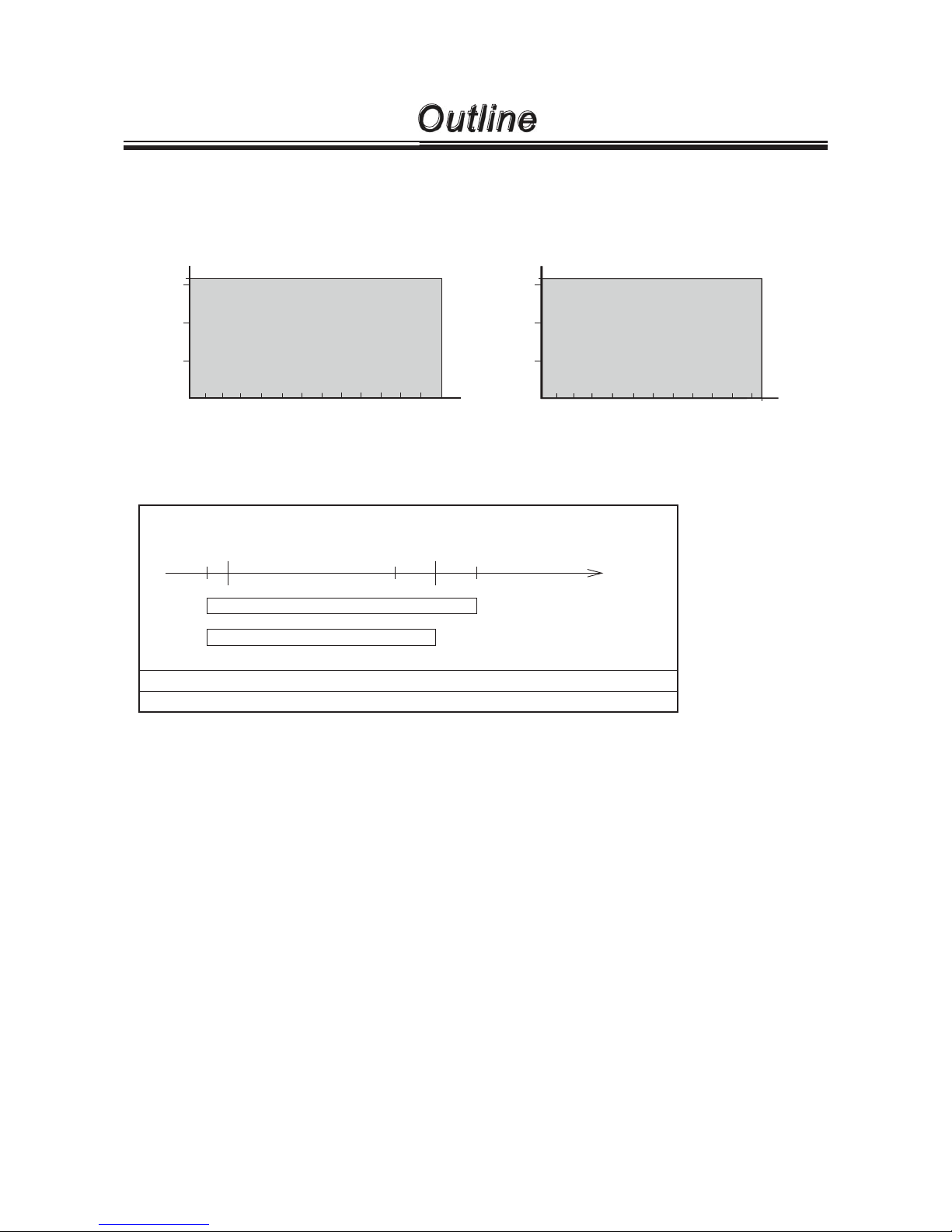
3. Maximum operating pressure (Discharge pressure limit)
See the graph below for the maximum operating pressure. Always keep a pressure in the pump head
within the limit, taking account of specific gravity and suction pressure.
4. Liquid temperature at each model
* Note that viscosity, vapour pressure or corrosiveness changes with liquid temperature. The change is
shown in performance such as flow rate while the pump itself is not affected.
a. The pump may not send bubbly liquid or high vapour temperature liquid. The allowable liquid tempera-
ture range changes with chemical liquid.
b. Contact us when liquid temperature is at or below 0°C or beyond the allowable liquid temperature
range. The relation between temperature and viscosity, corrosion resistance, freezing, and condensing
need to be taken into consideration.
c. The allowable liquid temperature range changes with each chemical. See the corrosion resistant table
in a separate volume of the Technical information for the allowable liquid temperature range at each
chemical.
5. When sending high or low temperature liquid
For high temperature liquid transfer, observe the operating temperature limit of the motor. For low tem-
perature liquid transfer, condensation may build up on the drive magnet and rear casing. In this case, con-
duct dehumidification.
Surrounding temperature range: 0- 40°C
Ambient humidity range: 35-85%RH
Allowable liquid temperature range
-10 0 105 120
MDW80/100
MDW50
80
Outline
80 105
1.6
MDW80/100
40
60
20
-10
0.5
1.0
Allowable area
80 100 120
Liquid temperature (ºC)
1.6
Pressure limit (MPa)
MDW50
40
60
20
-10
0.5
1.0
Allowable area
1.5
0
1.5
0
Liquid temperature (ºC)
Pressure limit (MPa)
Liquid temperature

- 13 -
6. Slurry
This pump is not designed for sending slurry but then is able to send slurry depending on concentration,
particle size and hardness. Contact us for detail.
7. Performance change with specific gravity and viscosity
Shaft power, a flow rate and a delivery head vary with the specific gravity and viscosity of liquid. The
pump is designed according to a specified condition. Contact us before changing the specified condition.
8. Use of pump under a negative pressure
Do not use the pump under a negative pressure. Otherwise, the rear casing may deform. If a decompres-
sion tank or sealed tank is used in your system, always keep the discharge pressure in the pump head to
atmospheric pressure or more at any time during operation or stop. Contact us for detail.
9. Storage
Observe the following requirements for the storage.
1. Cover the inlet and outlet for keeping away foreign matters.
2. The pump should be stored indoors, free from exposure to water and high humidity.
3. Drain liquid out of the pump unit completely for storage after operation. Clean and inspect the pump
unit as necessary.
* See manufacturer's instruction manual for the motor unit and coupling.
10. ON-OFF operation
Turning on/off power frequently, the pump is damaged. Keep the number of ON-OFF operations at or
below six times per hour.
11. Centring (Coupling)
Conduct centring after mounting/dismounting the pump or motor unit. See page 30 for centring. See man-
ufacturer's instruction manual to conduct centring by yourself.
Outline

- 14 -
Installation
1. Before installation
...............................
15
2. Pipework
.............................................
16
3. Wiring
.................................................
19
 Loading...