

IWAKI MDM 50, MDM 65, MDM 25, MDM 40 Instruction Manual
IWAKI Magnetic Drive Pump
MDM Series (Asia Edition)
Instruction Manual
Read this manual before use of product

Thank you for selecting IWAKI Magnetic Drive Pump MDM Series. This instruction man-
ual, which is divided into five sections, namely "Safety", "Outline of Product", "Installation",
"Operation" and "Maintenance", deals with the correct handling and operation procedures
for the pump. To make maximum use of the pump and to ensure safe and long time opera-
tion of the pump, please read this manual thoroughly and carefully prior to operating the
pump.
Contents
SAFETY SECTION
...........................................................................................
OUTLINE OF PRODUCT
1. Unpacking and inspection
2. Model code
3. Conditions to be used
4. Structure and names of parts
INSTALLATION
................................................................................................
5. Installation
6. Piping
.....................................................................................................................
7. Electrical wiring
8. Protection
OPER ATIO N
...................................................................................................
9. Precautions on operation
10. Operation (Starting)
11. Pump stopping
MAINTENANCE
.............................................................................................
12. Trouble shooting
13. Maintenance & inspection
14. Disassembling & assembling
15. Repair parts list
16. Mass of pump
..................................................................................
..............................................................................
............................................................................................................
......................................................................................
.......................................................................
...........................................................................................................
.................................................................................................
............................................................................................................
.............................................................................
........................................................................................
........................................................................
......................................................................
.......................................................
...................................................
.......................................................................
.........................................................................
1
4
5
6
7
8
9
10
11
13
13
14
15
16
16
17
18
20
21
27
42

SAFETY SECTION
For the Safe and Correct Handling of the Pump
● Before use of the pump, read carefully this "Safety Section" to prevent accidents and to avoid the
damage or loss of other assets.
● Observe and abide by the instructions described in this "Safety Section". These instructions are
very important for protecting pump users or other persons from hazard or from loss of assets.
● Meaning of symbols
Following two symbols describe the extent of hazards and loss which may brought if the instructions are not observed or if the pump is wrongly used.
Nonobservance or misapplication of the contents of
Warning
Caution
Following two symbols describe the content to be observed.
the "Warning" could lead to a death or heavy injury of
person.
Nonobservance or misapplication of the contents of the
"Caution" could lead to a injury of person or damage of
assets.
Prohibited action or procedure is indicated. Inside or
near this circle, a concrete activity to be prohibited is
depicted.
Action or procedure which must be performed without
fail is indicated. Inside this circle, a concrete activity to
be performed is depicted.
Export Restrictions
Technical information contained in this instruction manual might be treated as controlled
technology in your countries, due to agreements in international regime for export control.
Please be reminded that export license/permission could be required when this manual is
provided, due to export control regulations of your country.
-
1 -
Safety Section
Prohibited
Wear protective
gear
No Remodeling
WARNING
● Access limitation
The magnet drive pump has a pair of strong magnets (the magnet capsule
unit and drive magnet). The strong magnet field could adversely affect the
persons who are assisted by electronic devices such as the pacemaker.
● Turn off power before work
Be sure to turn off power to stop the pump and related devices before work.
Make sure no one turns on power by mistake while working on the pump,
otherwise it may result in a serious accident. If your working area is noisy or
dark, let other people know about the situation by displaying a notice such
as "POWER OFF (Maintenance)" near a power switch.
● Wear protective clothing
Always wear protective clothing such as an eye protection, chemical resist-
ant gloves, a mask and a face shield during disassembly, assembly or main-
tenance work.
● Use the eye bolt or lifting holes
Use the eye bolt when lifting the pump unit only or use lifting holes on the
base if the pump unit is mounted on it. In the latter case, do not use the eye
bolt. Use an overhead crane or any other proper transporting machine. Two
or more operators may be needed for ensuring safe transport depending on
the pump size and weight.
● Do not modify the pump
Alterations to the pump carries a high degree of risk. It is not the manufactur-
er’s responsibility for any failure or injury resulting from alterations to the pump.
Turning off p ower
● When handling dangerous liquid
For the transfer of the harmful liquid as mentioned below, be sure to conduct
daily inspection and maintenance for the prevention of liquid/gas leakage.
1. Explosive or flammable liquid
2. Corrosive chemicals
3. Harmful liquid or gas
● Ventilation
Fumes or vapours can be hazardous with certain solutions. Ensure proper
ventilation at the operation site.
-
2 -
Safety Section
Prohibited
Prohibited
CAUTION
● Do not catch the finger
Magnetic force of the pump is powerful. Take care not to catch the finger in the
bracket. Observe the instructions on the later pages for disassembly and assembly.
● Do not run pump dry
Do not run pump dry (operation without liquid). Friction heart builds up during
dry running operation and damages internal parts. If the pump is operated
with a suction side valve closed or without priming, the pump runs dry.
* The pumps with the carbon bearing (CF type) can run dry up to 1 hour without damaging internal
sliding parts (see page 15 as well).
● Qualified personnel only
The pump should be handled or operated by qualified personnel with a full
understanding of the pump. Any person not familiar with the product should
not take part in the operation or management of the pump.
● Do not use the pump/motor in any condition other than its intended purpose
The use of the pump/motor in any conditions other than those clearly specied
may result in failure or injury. Use this product in specied conditions only.
● Static electricity
When low electric conductivity liquids such as ultra-pure water and fluor inac-
TM
tive liquid (e.g. Fluorinert
) are handled, static electricity may generate in
the pump and may cause static discharge. Take countermeasures to remove
static electricity.
● Commissioning
Friction heat builds up and damages the internal parts. Break in the pump to
expel gas from the pump and piping, especially when handling liquids that
generate gas bubbles (sodium hypochlorite or hydrogen peroxide).
● Spill precautions
Ensure protection and containment of solution in the event of plumbing or
pump damage (secondary containment).
● Disposal of a used pump
Remove a chemical and ush it out before the pump is disconnected from pip-
ing. Dispose of any used or damaged pump in accordance with local rules and
regulations. If necessary, consult a licensed industrial waste disposal company.
-
3 -

OUTLINE OF PRODUCT
1. Unpacking and inspection
2. Model code
3. Conditions to be used
4. Structure and names of parts
-
4 -
..................................................
........................
...............................
..................
5
6
7
8
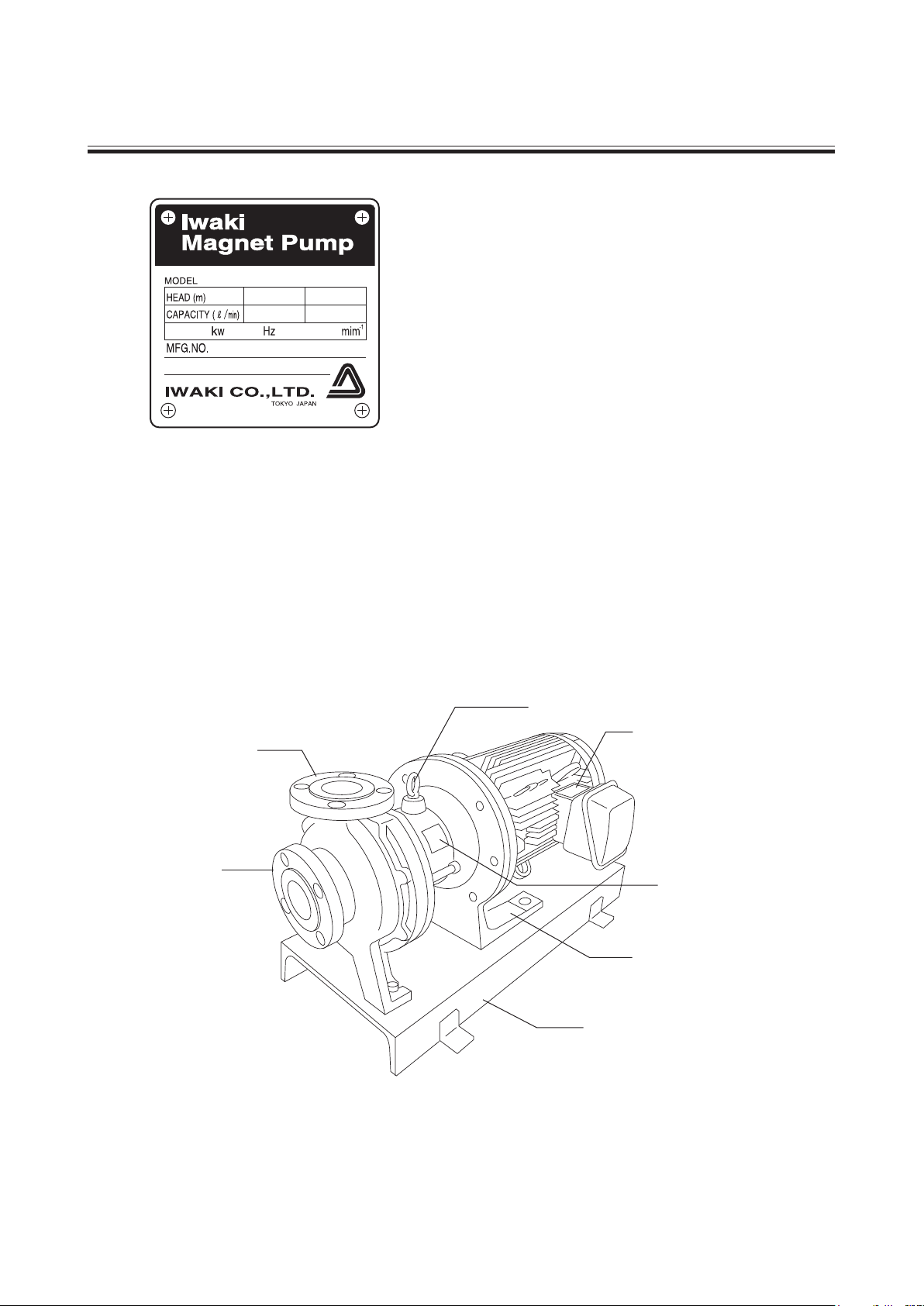
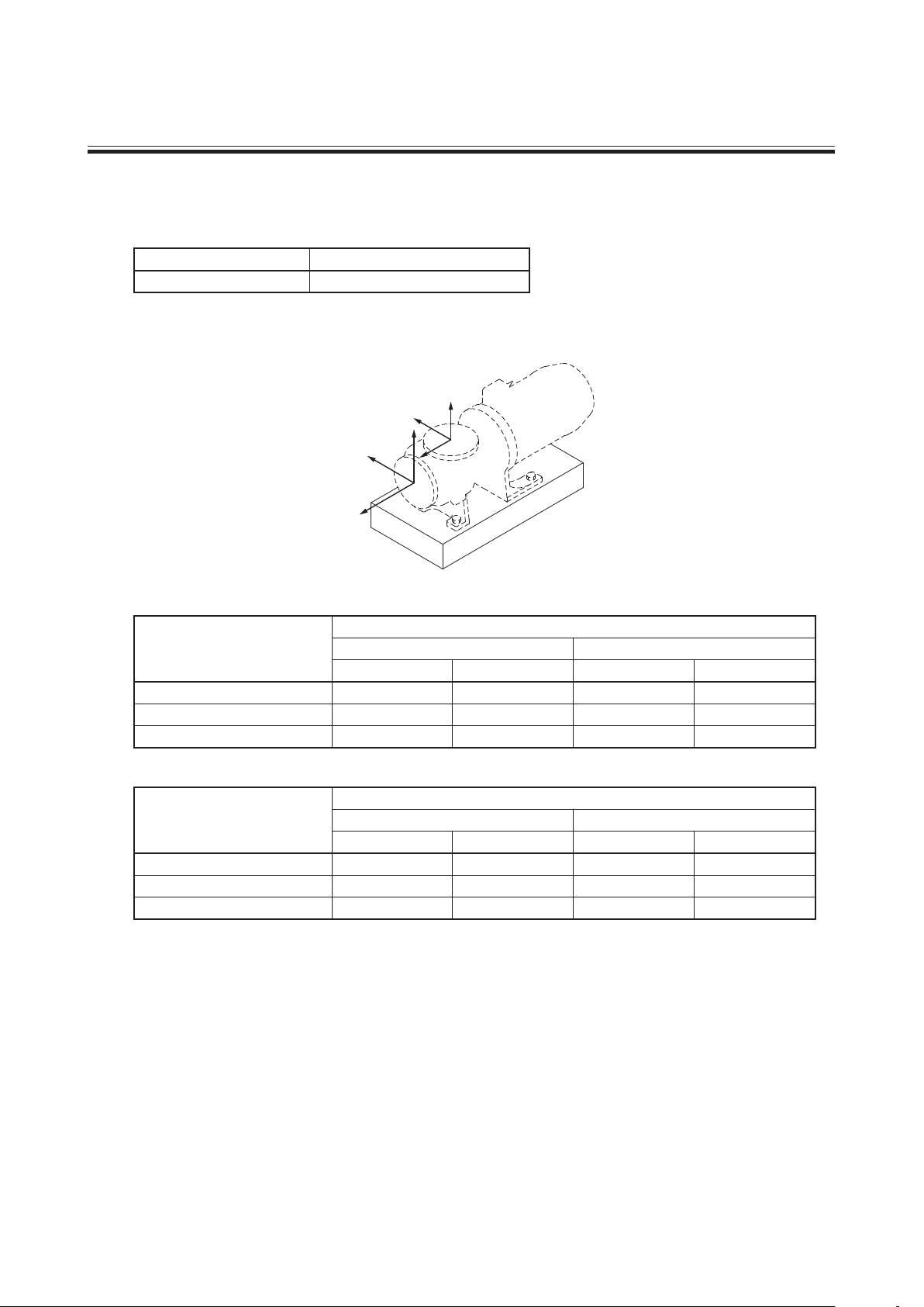
1. Unpacking and inspection
Eye bolt
Motor nameplate
Foot support
Pump nameplate
Baseplate
Suction port
Discharge port
After unpacking of the pump, check the following
points.
(1) If the product is ordered one.
(2) If the product is not damaged or bolts are not loos-
(3) If accessories are attached.
Check model code, discharge capacity, discharge
pressure, voltage which are written on nameplate
of pump and motor to see if they conform to your
order.
ened during transportation. Tighten especially the
bolts which are holding a rear casing support to the
specific tightening torque subsequent to the first
tightening. Refer to the "13.Disassembling & assem-
bling" for the specific torque value.
Standard accessories:
Bolts for back pull-out M12 × 100: 2pcs
(M10 × 50 : 2pcs for MDM25-1)
Optional accessories if ordered
-
5 -
2. Model code
MDM40 - 150 1 E KK F 075 J - D 2 H
1 2 3 4 5 6 7 8 9 10 11
1 Pump discharge bore Suction Discharge
25: 40 × 25
40: 50 × 40
50: 65 × 50
65: 80 × 65
2 Nominal impeller diameter: 100 - 225 (mm)
3 Impeller range: 1: Low head impeller type 2: High head impeller type (Available for MDM25 and MDM40)
3: High head impeller type (Available for MDM25 only)
4 Main material: E: CFRETFE P: PFA N: PFA (MDM25-2 and MDM40-1)
Note) Pumps with the "P" and "N" codes have PFA main materials, but then casing design is different from each other.
See the section 15. Spare parts list for detail.
5 Bearing/spindle material: KK:SiC/SiC CF:High density carbon/High purity ceramic
6 Type of motor to be mounted: F : Flange mounted motor type
7 Motor output: 004 : 0.4 kW, 007 : 0.75 kW, 015 : 1.5 kW, 022 : 2.2 kW,
037 : 3.7 kW, 055 : 5.5 kW, 075 : 7.5 kW, 110 : 11 kW, 150 : 15 kW, (185 : 18.5 kW)
8 Standard for connection flange/motor
J : JIS pump f lange + JIS motor I : ISO pump f lange + IEC motor A : ANSI pump f lange + JIS motor
9 Drain/special version
Drain
A
Without drain
S
D
With drain
X Special version
B
Without drain
Y
E
With drain
Z
Note: For the pumps with the main material code of "P", an air vent is always equipped for "with drain" type.
10 Motor pole : 2 : 2 pole motor
4 : 4 pole motor
11 High temperature type
No code : Standard
H : High temperature type
(Available for MDM25-3 and MDM40-2)
Note) In this manual, model code is simplified by using pump discharge bore code (1) and impeller range code (3). For
example, when you see MDM25-1, MDM25-2, MDM25-3, MDM40-2, the figures 25 or 40 are pump discharge
bore and 1, 2 or 3 are impeller range.
Baseplate Standard or Special version
Standard
With baseplate
Without baseplate
Special version
Standard
Standard
Special version
Standard
Special version
-
6 -
3. Conditions to be used
1. Maximum operating pressure
Maximum operating pressure of the pump is 1 MPa (1.6 MPa for MDM25-3 and MDM40-2). Pay attention so that
the pump discharge pressure does not exceed this figure.
2. Slurry containing liquid
Basically slurry containing liquid can not be handled but SiC bearing type (KK type) can handle it in the following
conditions:
• Slurry concentration up to 5 wt%
• Slurry hardness up to 80 Hs
• Slurry size up to 50 µm
3. Performance change caused by specific gravity and viscosity of liquid
When specific gravity and viscosity are larger than water, shaft power, discharge capacity and discharge head will
change depending on specific gravity and viscosity of pumped liquid. The pump was made and shipped according
to the information given to IWAKI. If the liquid condition is changed, ask and confirm IWAKI to use the pump
without problem.
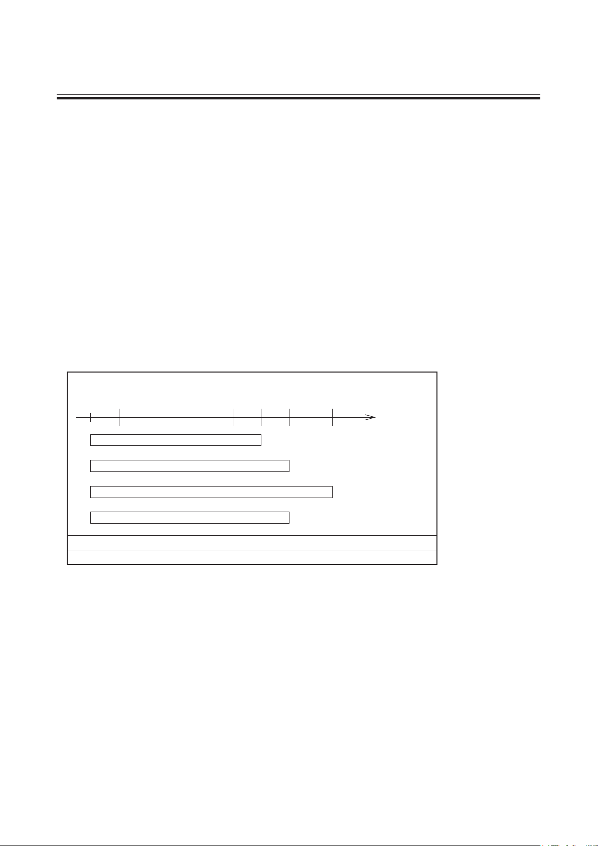
4. Inf luence by liquid temperature
The chemical liquid changes its viscosity, vapor pressure and corrosivity according to the temperature change. Pay
attention to the change of liquid characteristics.
Liquid temperature range
-20 0 100 150
E (all models)
P (MDM25-3/ 40-2)
P (MDM25-1/ 25-2/ 40-1/ 50-1/ 65-1)
N (MDM25-2/ 40-1)
12080
Pumped liquid
temperature (deg. C)
Ambient temperature range: 0 - 40 deg. C
Ambient humidity range: 35 - 85% RH
Note 1) The code "E", "P" and "N" represents main materials.
2) For temperature range of each chemical liquid, refer to Chemical Resistant Table on booklet "Technical
Information on MDM Series".
3) For liquid temperature below zero deg. C and above 120 deg. C, please contact IWAKI because detailed
operating condition must be considered for these temperature ranges.
-
7 -

4. Structure and names of parts
903.1
554.4
901.4
500.2
554.2
901.2
500.3
554.3
901.3
400.3
122.2
314.1
314.2
210
122.1
400.2
500.1
554.1
901.1
310
100.1100.2 230
859
161
858
942
400.1
314.4
554.5
901.5
314.3
554.6
900
908.1
554.7
901.7
901.6
801
890
159158
330159.1
NO. Parts name Q'ty NO. Parts name Q'ty
100.1 Front casing
100.2 Cover
122.1 Drain plate
122.2 Air vent plate
158 Rear casing
159 Rear casing cover
159.1 Reinforce pipe Note (2)
161 Rear casing support
210 Spindle
230 Impeller
310 Bearing
314.1 Liner ling
314.2 Mouth ring
314.3 Rear thrust
314.4 Rear ring
330 Bracket
40 0.1 Gasket
400.2 Drain gasket
400.3 Air vent gasket
50 0.1 Plain washer
500.2 Plain washer
500.3 Plain washer
Note
: Q'ty in parenthesis (6) is for MDM25-1 and (10) is for MDM25-3 & MDM40-2.
(1)
: For high temperature type "H" of MDM25-3 & MDM40-2.
(2)
: For pumps with the main material codes of "E" (all models), "P" (MDM25-1) and "N" (MDM25-2/40-1).
(3)
1
1
1
1
1
1
1
1
1
1
1
1
1
1
1
1
1
1
1
2
2
2
554.1 Spring washer
554.2 Spring washer
554.3 Spring washer
554.4 Spring washer
554.5 Spring washer
554.6 Spring washer
554.7 Spring washer
801 Motor
858 Drive magnet unit
859 Magnet capsule unit
890 Base plate
900 Eye bolt
901.1 Hex. head bolt
901. 2 Hex. head bolt
901.3 Hex. head bolt
901.4 Hex. head bolt
901. 5 Hex. head bolt
901.6 Hex. head bolt
901.7 Hex. head bolt
903.1 Hex. head bolt Note (3)
90 8.1 Hex. socket head bolt
942 Impeller pin
8 (6) or (10) Note (1)
8 (6) or (10) Note (1)
2
2
2
4
4
2
1
1
1
1
1
2
2
2
4
4
2
5
2
2
-
8 -

INSTALLATION
5. Installation
6. Piping
7. Electrical wiring
8. Protection
-
9 -
..................................................
..........................................................
...................................................
.........................................
10
11
13
13

5. Installation
1
2
3
11
10
13
10
12
11
6
5
9
7
4
8
7
12
Within
1m
Concrete foundation
Foundation bolt
Baseplate
liner
Example of recommended piping
1 Discharge pipe
2 Discharge valve
3 Check valve
4 Pressure gauge
5 Motor
6 Pump
7 Flexible joint
8 Vacuum gauge
9 Suction pipe
10 Suction valve
11 Gate valve
12 Air vent piping
13 Pipe support
1. Installed position
2. Location
3. Foundation
• If the pump unit is not anchored to the foundation and if the motor unit is heavier than the pump unit, the
entire pump leans towards to the motor. See page 42 as well.
• Install and fix the pump on the foundation which is not affected by vibration generated by other machines.
• Keep enough space around the pump for the back pull-out of motor, assembly and disassembly of the pump.
• Foundation area must be larger than pump base plate.
• Install the pump as close to the tank as possible and at lower position than the tank (flooded suction).
• If the pump is installed at the location that the pump suction port comes higher position than the liquid
level of tank (suction lift style), install the priming piping and foot valve at the end.
• Refer to illustration below.
-
-
10
6. Piping
Z
X
Y
X
Z
Y
1. Tightening of pipe flange
Table below shows the bolt size and tightening torque for the connection of pipe flange to pump flange. Tightening
torque is the figure when metallic f lange and rubber gasket are used.
Bolt size
M16
2. Pipe load and moment
Pipe load and moment put on the pump should not exceed the figures shown below.
Allowable pipe load on pump flange
Direction of load Suction flange
Fx
Fy (Pression/Tension) 0.58
Fz 0.89 0.71
Tightening torque
78.4 N · m
Load kN
Discharge flange
MDM25, 40, 50 MDM65 MDM65
0.71 0.89
0.89/0.44 1.33/0.67 0.89
0.58
1.07 1.33
MDM25, 40, 50
1.07
Allowable moment on pump flange
Moment kN
Direction of load Suction flange
MDM25, 40, 50 MDM65 MDM65
Mx
My 0.35
Mz 0.47 0.23
Discharge flange
0.46 0.46
0.35 0.72 0.72
0.23
0.95 0.95
·
m
MDM25, 40, 50
0.47
-
-
11

3. Suction piping
(1) Flooded suction
Flooded suction is recommended.
(2) Pipe diameter
Pipe diameter should be larger than pump inlet bore.
(3) Shortest piping
Employ less bends and shortest piping length.
(4) Straight piping
Employ straight pipe just before pump inlet port.
Pump inlet bore 50A or smaller : Straight pipe of 500 mm or longer
Pump inlet bore 65A or larger : Straight pipe of 8 times as larger than inlet port
For the easy pump dismantling and maintenance, install a removable short length pipe of 300mm or so in straight
piping.
(5) Air pocket in piping
Do not allow any projection in piping where air may be trapped along the suction pipe.
Suction pipe should have an ascending gradient of 1/100 toward the pump.
(6) Different diameter of pipes
If diameter of pump suction port is different from that of suction pipe, use the eccentric reducer pipe. Connect
the eccentric reducer pipe so that upper side is level. Residual air may not go out if it is mounted in reverse.
(7) Gate valve in suction side
In case of flooded suction, install gate valve in suction piping. It is needed when the pump is disassembled and
inspected.
(8) Piping for flushing
Install pump f lushing piping in case that the dangerous liquid will be handled.
(9) End of suction piping
The end of suction pipe always should be located 500 mm or more below the liquid level. Take care so that air
can not be sucked in suction piping.
(10) In case of suction lift piping
• The end of suction piping should be 1 to 1.5 times of pipe diameter or more away from the bottom of suction tank.
• Install foot valve or check valve in suction piping.
(11) Pipe support
Install the pipe support so that the weight of pipe can not be directly loaded to the pump.
(12) Pipe connection
Pipes must be connected securely so that the air can not be sucked in. If the sealing is not perfect, air is sucked
in, which causes pump damage.
4. Discharge piping
(1) Pipe diameter
In case the discharge piping is long, the specified performance may not be obtained because of unexpected pipe
resistance if the pipe diameter is the same as pump bore. Calculate the pipe resistance in advance to decide proper
diameter of pipe.
(2) Position of the first valve
Take 1m or so distance between pump and the valve located the nearest to pump and install air eliminating piping
at the place close to the nearest valve to the pump so that air can not remain in pump. Refer to "Example of recom-
mended piping" on page 10.
-
-
12

(3) Gate valve
Install the gate valve in discharge piping to adjust f low rate and to protect motor from over loading. If the check
valve is also installed, recommended arrangement is : Pump → Check valve → Gate valve
(4) Pressure gauge
Install a pressure gauge in discharge piping to check the operating conditions such as discharge head etc.
(5) Check valve
Check valve must be installed in the following cases.
• Discharge piping is longer than 15 to 20 meters.
• Actual head exceeds 15 meters.
• Height difference between liquid level and discharge pipe end exceeds 9 meters.
• When two pumps are used in parallel.
(6) Air vent
If horizontal discharge piping is longer than 15 to 20 meters, install air vent on the way.
(7) D rain
If the liquid must be drained to protect from freezing, install the drain valve.
(8) Pipe support
Install the pipe support so that the pipe weight can not be loaded to pump.
(9) Priming piping
Install piping for priming in case of suction lift.
7. Electrical wiring
Electrical works or wiring must be carried out by qualified and authorized person according to local law or regulation.
• Use the electromagnetic switch which conforms to motor specifications such as voltage and capacity etc.
• If pump is installed outdoor, wiring must be done so that water can not get into switch.
• Electromagnetic switch and push-button switch must securely installed apart from the pump.
• Star-delta starter, inverter or soft starter is recommended to start the motor of 5.5 kW or more power which drives the pump.
* See the instruction manual of the motor manufacturer for the handling of the motor.
8. Protection
It is recommended to install the following monitoring devices to protect the pump.
1. Current sensor/Power sensor The sensors monitor the motor load and stop the pump on the detection of load change.
2. Pressure sensor The sensor monitors the starting pressure and stops the pump on the detection of
pressure change.
3. Flow sensor The sensor monitors the discharge f low and stops the pump on the detection of
flow change.
4. Level sensor The sensor monitors the liquid level and stops the pump when it falls below the
specified level.
It is recommended to install two or more monitoring devices. The more monitoring devices are installed, the more
possibility of protecting the pump.
The DRN series pump protector (an electric current sensing type abnormal operation preventive device) is also avail-
able as an option. Contact us for detail.
-
-
13
 Loading...