

IWAKI MDK Series, MDK-25, MDK-20, MDK-32, MDK-40 Instruction Manual
IWAKI Magnetic Drive Pump
MDK Series
Instruction Manual
Read this manual before use of product
(Europe Edition)

Thank you for selecting IWAKI Magnetic Drive Pump MDK Series. This instruction manual,
which is divided into five sections, namely "Safety", "Outline of Product", "Installation",
"Operation" and "Maintenance", deals with the correct handling and operation procedures for
the pump. To make maximum use of the pump and to ensure safe and long time operation of
the pump, please read this manual thoroughly and carefully prior to operating the pump.
Contents
Safety section
Outline of product
1. Unpacking and inspection
2. Operating principle
3. Model identification
4. Specification
5. Construction and material
6. Outline dimension
7. Performance curve
.............................................................................
......................................................................
.....................................................
................................................................
................................................................
..........................................................................
.....................................................
..................................................................
................................................................
8. Construction and parts names
Installation
................................................................................
1. Precautions before use of pump
2. Plumbing
3. Electrical wiring
Operation
.................................................................................
1. Precautions on operation
2. Preparation for operation
3. Operation
4. To stop pump
.............................................................................
...................................................................
....................................................
.....................................................
.............................................................................
.......................................................................
1~4
5~9
..............................................
10~16
.........................................
17~19
6
6
6
7
7
8
8
9
11
14
16
18
18
19
19
Maintenance
1. Troubleshooting
2. Maintenance and inspection
3. Consumable parts
............................................................................
...................................................................
................................................
...............................................................
4. Disassembling and assembling
20~27
...........................................
21
22
24
25
Safety section
For the Safe and
Correct Handling of the Pump
● "Safety Instruction" section deals with important details about handling of the product. Before
use, read this section carefully for the prevention of personal injury or property damage.
● Observe the instructions accompanied with "WARNING" or "CAUTION" in this manual. These
instructions are very important for protecting users from hazardous situations.
● The symbols on this instruction manual have the following meanings:
Nonobservance or misapplication of “Warning” sec-
WARNING
tions could lead to a serious accident which may
result in death.
Nonobservance or misapplication of “Caution” sec-
CAUTION
tions could lead to personal injury or property damage.
Types of Symbols
Indicates that “Warning” or “Caution” must be exercised. Inside this triangle, a con-
crete and practical image provided as a warning or caution message is depicted.
Indicates a prohibited action or procedure. Inside or near this circle, a concrete and
practical image of the activity to be avoided is depicted.
Indicates an important action or procedure which must be performed or carried out
without fail. Failure to follow the instructions herein can lead to malfunction or
damage to the pump.
Export Restrictions
Technical information contained in this instruction manual might be treated as controlled
technology in your countries, due to agreements in international regime for export control.
Please be reminded that export license/permission could be required when this manual is
provided, due to export control regulations of your country.
- 1 -
Safety section
Prohibited
Wear protective
gear
No Remodeling
Caution
Prohibited
WARNING
● Turn off power before service
Risk of electrical shock. Be sure to turn off power to stop the pump and
related devices before service is performed.
● Wear protective clothing
Always wear protective clothing such as an eye protection, chemical re-
sistant gloves, a mask and a face shield during disassembly, assembly or
maintenance work. The specic solution will dictate the degree of protec-
tion. Refer to MSDS precautions from the solution supplier.
● Use strong ropes (chains) for lifting up the pump
Serious injury may result if lifting ropes (chains) break. Check lifting ropes
(chains) are strong enough before use. Observe the maximum weight.
● Do not modify the pump
Alterations to the pump carries a high degree of risk. It is not the manufactur-
er’s responsibility for any failure or injury resulting from alterations to the pump.
● Access limitation
The magnet drive pump has a pair of strong magnets. The strong magnet
field could adversely affect the persons who are assisted by electronic
Turning off p ower
devices such as the pacemaker.
● Stop operation
If you notice any abnormal or dangerous conditions, suspend operation
immediately and inspect/solve problems.
● When handling hazardous liquid
For handling harmful liquids as mentioned below, be sure to conduct daily
inspection and maintenance for the prevention of liquid leakage. Otherwise
personal injury, explosion or fire may result.
1. Explosive or flammable liquid
2. Corrosive or stimulus toxic liquid
3. Health hazardous liquid
● Do not catch the finger
Magnetic force of the pump is powerful. Take care not to catch the finger in
the bracket.
- 2 -
Safety section
Prohibited
Prohibited
Prohibited
Prohibited
Prohibited
Caution
CAUTION
● Qualified personnel only
The pump should be handled or operated by qualified personnel with a full
understanding of the pump. Any person not familiar with the product should
not take part in the operation or management of the pump.
● Do not use the pump in any condition other than its intended purpose
The use of the pump in any conditions other than those clearly specied
may result in failure or injury. Use this product in specied conditions only.
● Use specified power only
Do not apply power other than that specied on the nameplate. Otherwise,
failure or re may result. Ensure the pump is properly grounded.
● Ventilation
Fumes or vapours can be hazardous with certain solutions. Ensure proper
ventilation at the operation site.
● Spill precautions
Ensure protection and containment of solution in the event of plumbing or
pump damage (secondary containment).
● Do not run pump dry
Do not run pump dry (Operation without liquid). Friction heart builds up dur-
ing dry running operation and damages internal parts. If the pump is oper-
ated with a suction side valve closed or without priming, the pump runs dry.
● Do not operate the pump in a flammable atmosphere
Do not place explosive or ammable material near the pump.
● Do not stand on the pump
Do not use the pump as a platform. Injury or damage may result when the
pump turns over.
● Do not touch the pump or pipe with bare hands
Risk of burning. The surface temperature of the pump or pipe rises high
along with liquid temperature in or right after operation.
- 3 -
Safety section
Caution
Grounding
Electrical shock
Prohibited
Caution
Prohibited
CAUTION
● Grounding
Risk of electric shock! Always properly ground the pump. Conform to local
electric codes.
● Install a GFCI (earth leakage breaker)
An electrical failure of the pump may adversely affect other devices on the
same line. Purchase and install an earth leakage breaker separately.
● Do not install/store the pump:
• In a ammable/explosive/corrosive atmosphere.
• In a dusty/humid environment.
• Where ambient temperature can exceed 0-40°C.
• Under mechanical vibrations.
• In direct sunlight or wind & rain.
● Starting
The pump doesn’t have an ON-OFF switch. The pump starts as a power
cable is plugged in.
● Foreign matter
When foreign matters enter the pump, turn off power at once and remove
them. Using the pump with foreign matters may result in failure.
● Disposal of a used pump
Dispose of any used or damaged pump in accordance with local rules and reg-
ulations. If necessary, consult a licensed industrial waste disposal company.
● Static electricity
When low electric conductivity liquids such as ultra-pure water and fluor
inactive liquid (e.g. FluorinertTM) are handled, static electricity may generate
in the pump and may cause static discharge. Take countermeasures to
remove static electricity.
● Preventative maintenance
Follow instructions in this manual for replacement of wear parts. Do not
disassemble the pump beyond the extent of the instructions.
● Do not use a damaged pump
Use of a damaged pump could lead to an electric shock or death.
- 4 -

OUTLINE OF PRODUCT
1. Unpacking and inspection .................. 6
2. Operating principle ............................. 6
3. Model identification ............................. 6
4. Specification ....................................... 7
5. Construction and material ................... 7
6. Outline dimension ............................... 8
7. Performance curve ............................. 8
8. Construction and parts names ............ 9
- 5 -
1. Unpacking and inspection
After the product is unpacked, check followings.
1) Identify the product
Check nameplate if pump model, head, frequency,
discharge capacity, motor power, voltage etc. are correct.
2) Damage during transportation
Check if the product is not damaged and bolts and nuts
are not loosened during transportation.
3) Discharge and suction ports are plugged so that foreign
matters do not get into pump chamber. Remove the plug
when the product is installed.
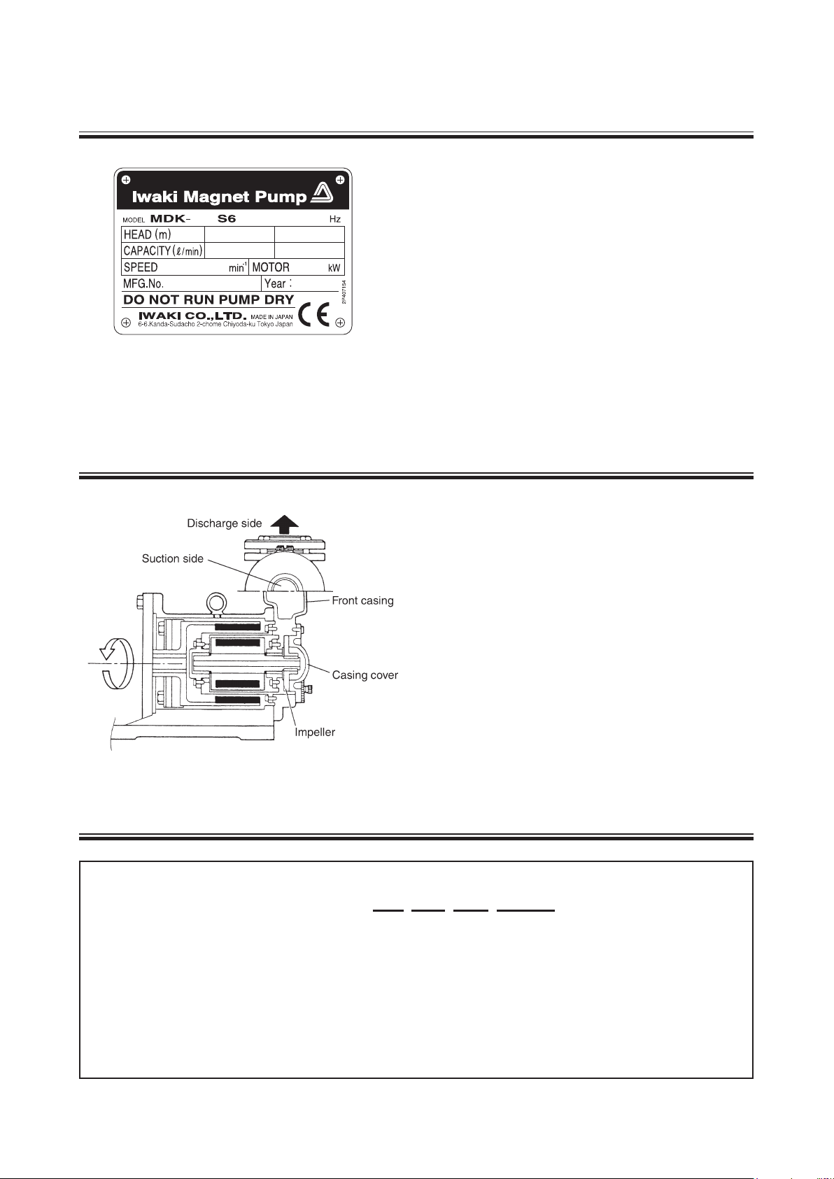
2. Operating principle
MDK Series pumps are magnetically driven turbine pump.
Impeller is rotated in pump chamber by the magnetic
coupling force to suck liquid from suction port and to
discharge to outlet.
3. Model identification
MDK ‒ 32 S6 TS EUR
(1) Pump bore : 20 ... 20mm, 25 ... 25mm, 32 ... 32mm, 40 ...40mm
(2) Pump material : S6 ... SCS14, SUS316, SUS329J1
(3) Check valve material : TS ... PTFE, SUS316
(4) Bearing material : EUR ... Carbon
EUR-R ... PTFE
(1) (2) (3) (4)
- 6 -
4. Specification
Model Bore
MDK-20
MDK-25
MDK-32
MDK-40
20mm
(Rp3/4)
25mm
(Rp1)
32mm
(Rp1-1/4)
40mm
(Rp1-1/2)
Standard flow rate (L/min.)
50Hz 60Hz
9 - 10 12 - 12.5 1.3 0.2
12 - 15 16 - 18.5 1.3 0.37
25 - 29 30 - 36 1.3 1.5
30 - 45 40 - 60 1.3 4.0
■ Pump weight with no motor
MDK-20 MDK-25 MDK-32 MDK-40
15kg 20kg 25kg 50kg
Specific
gravity limit
Motor
power (kW)
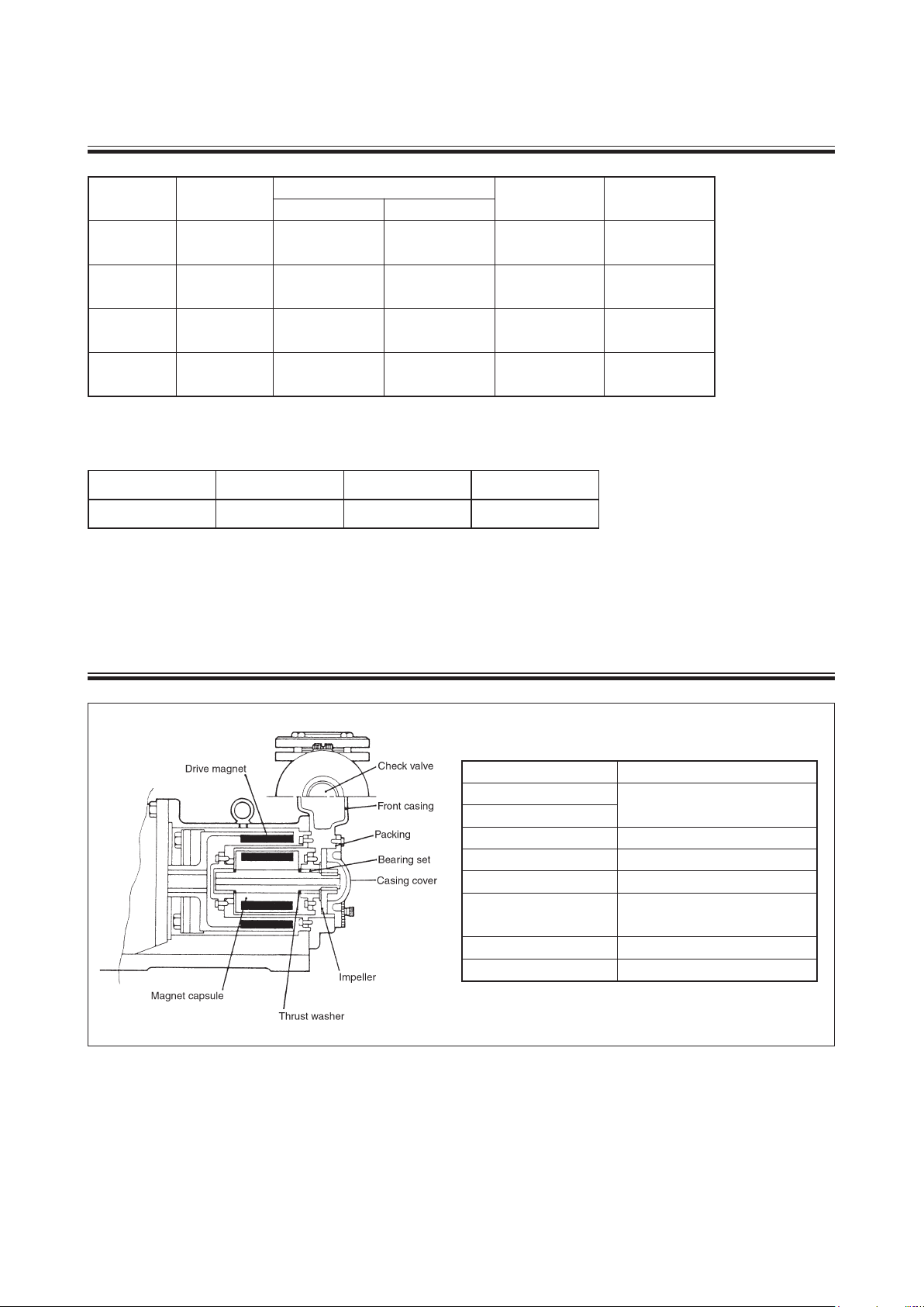
5. Construction and material
■ Wet end material
Casing
Casing cover
Impeller SUS316
Magnet capsule unit SUS329J1 + SUS316
Thrust washer PTFE
Bearing set
Cover packing PTFE
Check valve PTFE/SUS316
Parts Material
SCS14
Carbon/SCS14,SUS316 or
PTFE/SCS14,SUS316
- 7 -
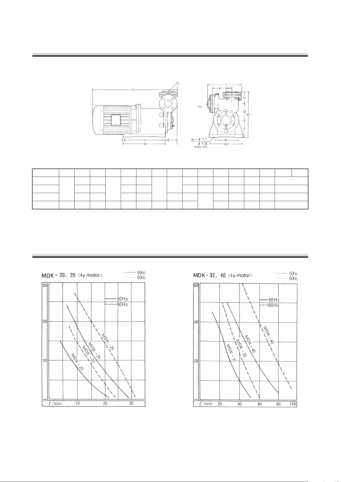
6. Outline dimension
Model W H a b c d e f g h i j k m n
MDK-20
MDK-25 267 200 140 50 100 77 63 228 96 (Rc1)
MDK-32 317 235 175 46 11 0 110
MDK-40 270 362 310 20 270 44 230 135 130 70 269 110 (Rc1-1/2)
180
260 140
30
80 44
150
95 75 50 209 90 (Rc3/4)
90
68 234 90 (Rc1-1/4)
97
l
20
27
40
45
7. Performance curves
- 8 -
 Loading...