

IWAKI MDE32-140, MDE32-110, MDE32-150, MDE32-170, MDE32-160 Instruction Manual
...
Read this manual before use of product
IWAKI
Magnetic Drive Pump
Model MDE
Instruction Manual

Thank you for selecting the IWAKI Magnetic Drive Pump type MDE. This instruction
manual has been prepared to ensure correct and safe handling of the pump. Please read this
manual carefully and thoroughly prior to operating the pump.
Pay special attention to the "Safety Instruction to Prevent Personal Injuries," "Warning," and
"Caution" messages included in this manual.
This instruction manual should be kept by each end user and within reach of the actual
operator, for quick reference when needed.
Contents
IMPORTANT INSTRUCTIONS
................................................
1~5
Safety Instructions to Prevent Personal Injuries
OUTLINE OF PRODUCT
......................................................
6~14
1. Before Using Pump
..................................
7
2. Operating Principle
..................................
7
3. Identification Codes
..................................
8
4. Specifications
and Outer Dimensions
......................
9
5. Names of Parts
......................................
12
PUMP OPERATION
..............................................................
15~28
1. Handling Instructions
............................
16
2. Installation
..............................................
19
3. Piping
......................................................
20
4. Wiring
....................................................
24
5. Operation Step
......................................
25
MAINTENANCE
....................................................................
29~46
1. Causes of Trouble
and Troubleshooting
........................
30
2. Maintenance and Inspection
..................
33
3. Spare Parts
............................................
36
4. Disassembly and Assembly
..................
37
Please contact the IWAKI sales office or IWAKI dealer for any
inquiries or questions regarding this product.

- 1 -
IMPORTANT INSTRUCTIONS
Important notes and statements for safe operation, preventing physical injury, and property
damage, are included on the body of the product and in the attached instruction manual.
Always Observe These Safety Instructions!
Safety Instruction to Prevent Personal Injuries
Warning
Ignoring this message can lead to improper
handling resulting in death or serious injury to the
operator.
Caution
Ignoring this message can lead to improper
handling resulting in injury to the operator or
damage to the product.
- 2 -
Caution
Wear
protective gear
Caution
Prohibited
Power off
Caution
Prohibited
Caution
Prohibited
Safety Section
WARNING
• Damaged or deteriorated tools are very dangerous. Use qualified and suitable tools
only.
• Use of protectors: When disassembling, assembling, and conducting maintenance or
when handling a dangerous type of liquid or a liquid of unknown property, be sure to
wear safety gloves, a helmet, and protective shoes. In addition, when handling wetend parts, always wear protective goggles, masks, etc.
• To prevent death or injury from a falling pump, make sure the rope or chain used for
lifting the pump is not accientally cut or disconnected during installation. Make sure
the rope or the chain used to lift the pump has sufficient strength in relation to the
pump load. Also, be sure not to stand underneath a lifted or suspended pump.
• When fixing the pump with rope or chain, be sure to use special bolts (or rings) for lifting. Never use any other points for lifting the pump.
• Always turn off the power supply prior to servicing the pump. Make special provisions so that no other operator mistakenly turns on the power supply while someone
is working on the pump. In a noisy or poor visibity environment, display a sign near
the power supply switch to notify others that someone is "WORKING" on the pump.
Power supply mistakenly turned on during maintenance may lead to personal injury.
Each operator must be especially careful of power supply operation.
• To ensure greater safety, check and make sure that there is no one near the pump
when switching on the power supply. The pump is not equipped with an ON/OFF
switch. Connecting the power cable or power plug supplies the power to the pump
and starts the operation.
• Run the pump at the specified power supply voltage on the nameplate only.
Otherwise, fire or electric shock may result.
• If the pump operation is stopped due to a power failure or closure of discharge wire,
turn off the power switch at once. After normal conditions return, turn the switch on
again.
• Do not use the pump for anything that it is not designed to do. User’s failure to
observe this instruction exempts IWAKI from any responsibility for personal injury or
damage to the equipment or facility caused by the pump's misuse.
- 3 -
WARNING
• Do not allow toxic substances such as lubricants, solvents, or similar substances to
flow into the local sewage system or river systems. Do not drain hazardous liquids
such as chemical solutions discharged out of the pump directly onto the ground.
Instead, drain such liquids into some kind of container. Observe the laws and regulations related to the application, handling, and processing of hazardous substances.
• Do not pass under a raised pump.
Never pass under a raised pump. A serious injury could occur if the pump is accidentally dropped.
• No remodeling
Remodeling of the pump by the user may result in serious personal injury, electric
shock, or damage to the pump. Do not attempt remodeling as it is very dangerous.
• Be careful with rotating elements.
Rotating elements such as the shaft, coupling, etc., can cause a serious personal
injury by seizing fingers, hands, hair, etc. Be careful not to touch such rotating elements while the pump is in operation.
• When the pumps are used to transfer the dangerous liquids mentioned as below, the
pumps always must be checked and watched so that the liquids can not be leaked.
The operation of the pumps leaking the liquids may result in personal injury and/or
explosion, fire accidents.
• Explosive, fire-spreading and inflammable liquids
• Corrosive and stimulus toxic liquids
• Liquids detrimental to health
CAUTION
• Qualified operators only
The pump operator and pump operation supervisor must not allow any operators who
have little or no knowledge of the pump to run operate the pump. Pump operators
must have a sound knowledge of the pump and its operation.
• For specified application only
The pump is designed and manufactured to the specifications agreed upon by the
user and IWAKI. The use of a pump in any application other than those clearly specified may result in injury or damage to the pump. Use the pump strictly in accordance
with the pump specifications and application range. If you change any specification,
contact IWAKI or your dealer.
Prohibited
No Remodeling
caution
Safety Section
Prohibited
- 4 -
CAUTION
• Ventilate
Poisoning may result during an operation which involves toxic or odorous liquid.
Ventilate the operating site sufficiently.
• Spill-out prevention measures
Appropriate protective measures should be taken against any spill-out accidents
involving the operating liquid as a result of unexpected damage to the pump or the
piping. Never discharge hazardous liquid, including, but not limited to, chemical liquid, over the ground or floor on the pump operating site. Follow local rules and regulations in disposing of hazardous substances.
• Do not operate the pump dry.
Do not run the pump dry (without liquid inside the pump). Heat generated as a result
of abrasion between elements inside the pump during operation without liquid may
damage the inside of the pump. Operating the pump with the suction valve fully
closed will result in dry operation.
• Keep away from heat or flame.
Do not place any open flame or flammable object near the pump.
• Do not stand on the pump.
Do not stand on the pump or use the pump as a step under any circumstances.
Otherwise, you may experience a serious injury.
• Do not touch the pump.
When the pump is used to feed a hot liquid, do not touch the pump or the piping with
your bare hands during and immediately after operation as their surfaces are dangerously hot.
• Arrange grounding
Do not operate the pump without connecting the grounding wire. Otherwise, an electrical shock may result. Make sure the grounding wire is connected with the grounding terminal.
• Install an earth leakage breaker
The operation of a pump without using an earth leakage breaker may cause an electrical shock. Please install an optional leakage breaker in the system.
• Countermeasure for static electricity
When low electric conductivity liquid such as ultra-pure water and fluor inactive liquid(e.g.FluorinertTM) are handled,the static electricity may be generated in
pump,which may cause static discharge and break down.Take countermeasure to
avoid and remove static electricity.
Caution
Grounding
Caution
Prohibited
Prohibited
Prohibited
Electrical
Shock
Safety Section
Caution
- 5 -
CAUTION
• Do not install or store the pump in the following places.
•
Places where flammable gas, dust or material is used or placed.
•
Places where corrosive gas (chlorine gas or the like) is generated.
•
Places where the ambient temperature is extremely high (40 °C or higher) or
extremely low, 0 °C or lower.
•
Places where the pump is exposed to extreme dust or humidity. (Excluding the outdoor type)
•
Places where vibrations occur.
• Pump start-up
When connecting a power supply to the pump, make sure there is no person around
the pump. The pump has no ON/OFF switch. The pump starts operation when the
power is supplied by connecting the power supply cable.
• Foreign matter
Should foreign matter enter the pump, turn off the power at once and remove the
obstruction. Using the pump with foreign matter inside may cause damage to the
pump or a malfunction.
• Disposal of used pump
Disposal of used or damaged pumps must be done in accordance with local laws and
regulations. (Consult a licensed industrial waste products disposing company.)
• The flange type motor is so heavy that it may fall over against the motor following disassembly of the pump. Make sure to support the motor by using a crane or other
heavy-duty support system.
• Handling of magnet coupling
The magnet used in the pump has a very high magnetic power. Be careful not to
allow your fingers to be seized by the magnet or to allow the magnet near any electronic device which may be affected by the magnet's power.
As a flange type driving magnet requires special equipment to hold it in place, do not
remove it from the shaft . In case removal is necessary, contact IWAKI or your dealer.
• Suspending pump operation for a prolonged period
When suspending pump operation for a prolonged period, drain the pump and clean
inside the pump. Take appropriate measures to prevent the entrance of foreign matter into the pump. If the pump is not operated for a period longer than one year,
replace the gasket and inspect inside the pump.
Caution
Caution
Safety Section
Prohibited

OUTLINE OF PRODUCT
1. Before Using Pump
..........................
7
2. Operating Principle
..........................
7
3. Identification Codes
..........................
8
4. Specifications and
Outer Dimensions
............................
9
5. Names of Parts
..............................
12
- 6 -
- 7 -
After unpacking, check the following points to confirm that
the delivered product and its accompanying parts and
elements are exactly what you ordered.
When lifting the pump please follow the procedure
mentioned "2. Installation" of "Pump operation".
[1] Does the model indicated on the nameplate conform to
your order?
[2] Has the pump unit or any part of it been damaged or
bolts and nuts been loosened during delivery?
[3] MFG.No. shows the year the product was
manufactured.
(e.g.1) When first numeral is "7".
7××5×××
The forth numeral of MFG.No. shows the
product was manufactured.
"5" shows the product was manufactured in the
year 1995.
(e.g.2) When first numeral is not "7".
××5×××
The third numeral of MFG.No. shows the year
the product was manufactured.
If you find anything wrong, please refer to the dealer you
placed your order with.
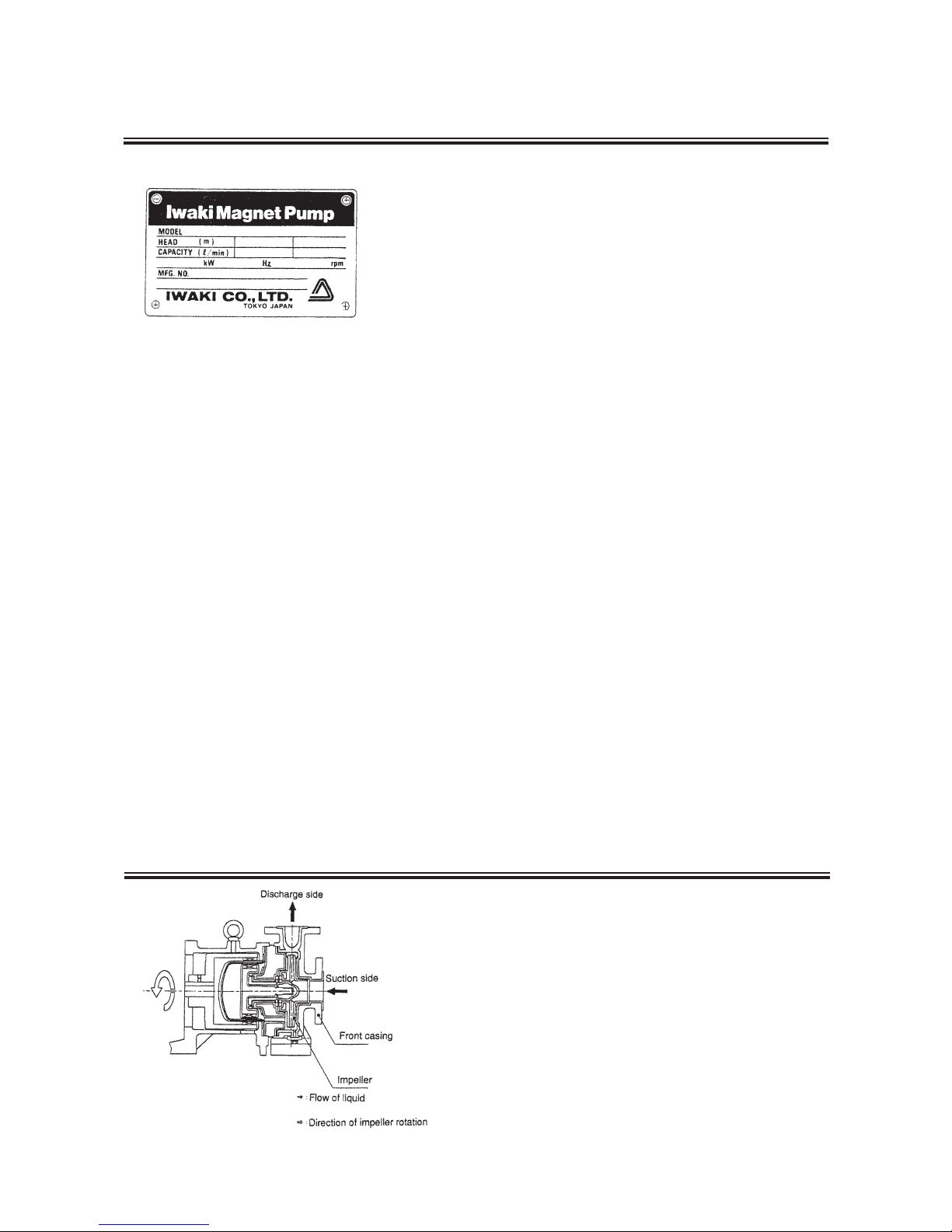
1. Before Using Pump
2. Operating Principle
The MDE pump is a magnet-driven centrifugal type pump
developed for various applications.
The impeller inside the pump chamber (front casing) is
rotated by magnetic force to transfer liquid from the suction
side to the discharge side.
The MDE type pump features excellent corrosion
resistance, durability, and safety, and serves as a chemical
pump for various processes. Most chemicals can be
handled by the pump.
- 8 -
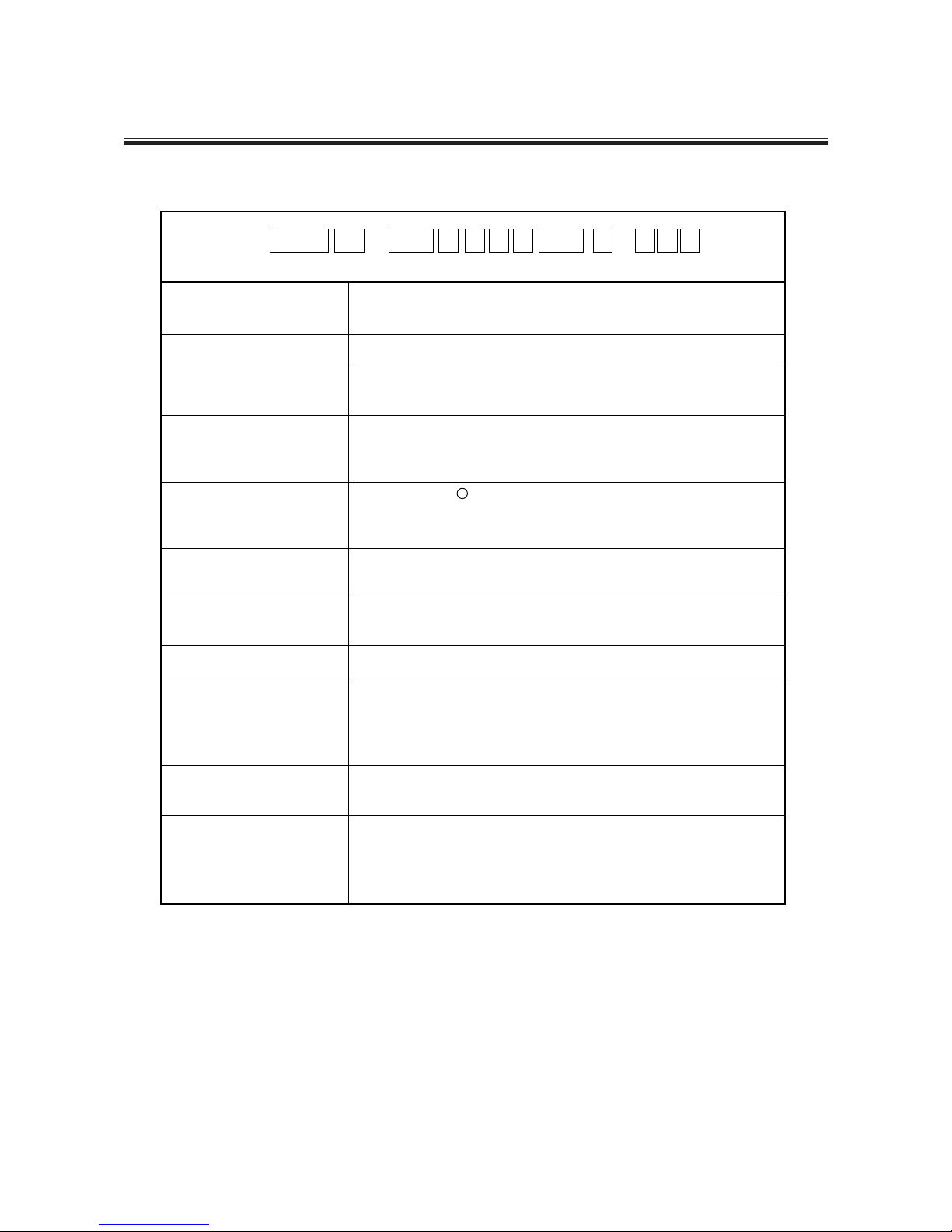
3. Identification Codes
Example:
MDE 32 - 160 E K V F 055 I - A 2 1
Nominal bore size Suction◊Discharge
32: 50A◊32A, 40: 65A◊40A, 50: 80A◊50A
Nominal Impeller size 100 ~ 200
Materials of
liquid-contact parts
P: PFA, E: ETFE, V: PVDF
Materials of bearing
and spindle
K: SiC
C: Ceramics+Carbon (bearing)
R: Ceramics+PTFE (bearing)
Type of motor C: Foot mount type motor
F: Flange mount type motor
Motor output 040: 4.0kW, 055: 5.5kW, 075: 7.5kW,
110: 11kW, 150: 15kW
A:
D:
S:
X:
Pump standard I: ISO
2: 2P, 4: 4P
No core :
1:
3:
5:
Special version
The number of
motor poles
Option
Without drain, no element made to order
With drain, no element made to order
Without drain, element made to order
With drain, element made to order
Without option
With leak sensor 2: With bearing temperature monitor
With bearing creep sensor 4: With bearing flusher
With inducer 9: With two or more option
q
q
w
e
r
Materials of O-ring Z: KALREZ
V: FKM
E: EPDM
t
y
u
i
o
!0
!1
w e r t y u i o !0 !1
R

- 9 -
4. Specifications and Outer Dimensions
Models
Nominal bore size
Suction Port◊
Discharge Port
Capacity
l/min
Head
m
MDE32-100
110
120
130
140
150
160
170
180
190
200
MDE40-100
110
120
130
140
150
160
MDE50-100
110
120
130
140
150
160
170
180
190
200
50A◊32A
65A◊40A
208
417
80A◊50A
833
16.0
19.0
22.5
27.0
30.0
34.0
38.5
39.0
44.0
49.0
52.5
14.0
18.0
22.0
25.0
29.5
33.0
36.5
40.0
43.5
49.0
52.5
9.5
12.5
19.0
23.5
28.5
33.0
36.0
Temperature range
of liquid handled
Allowable slurry
Motor (standard)
Color of paint
ETFE: 0~100˚C, PFA: 0~120˚C, PVDF: 0~90˚C,
Hardness: Below 80Hs
Particle size: Below 50µm (Concentration up to 5wt%)
3-phase IEC, Foot mounted or Flange mounted type
Munsell 2.5R 3.5/6
bb
Common Specifications
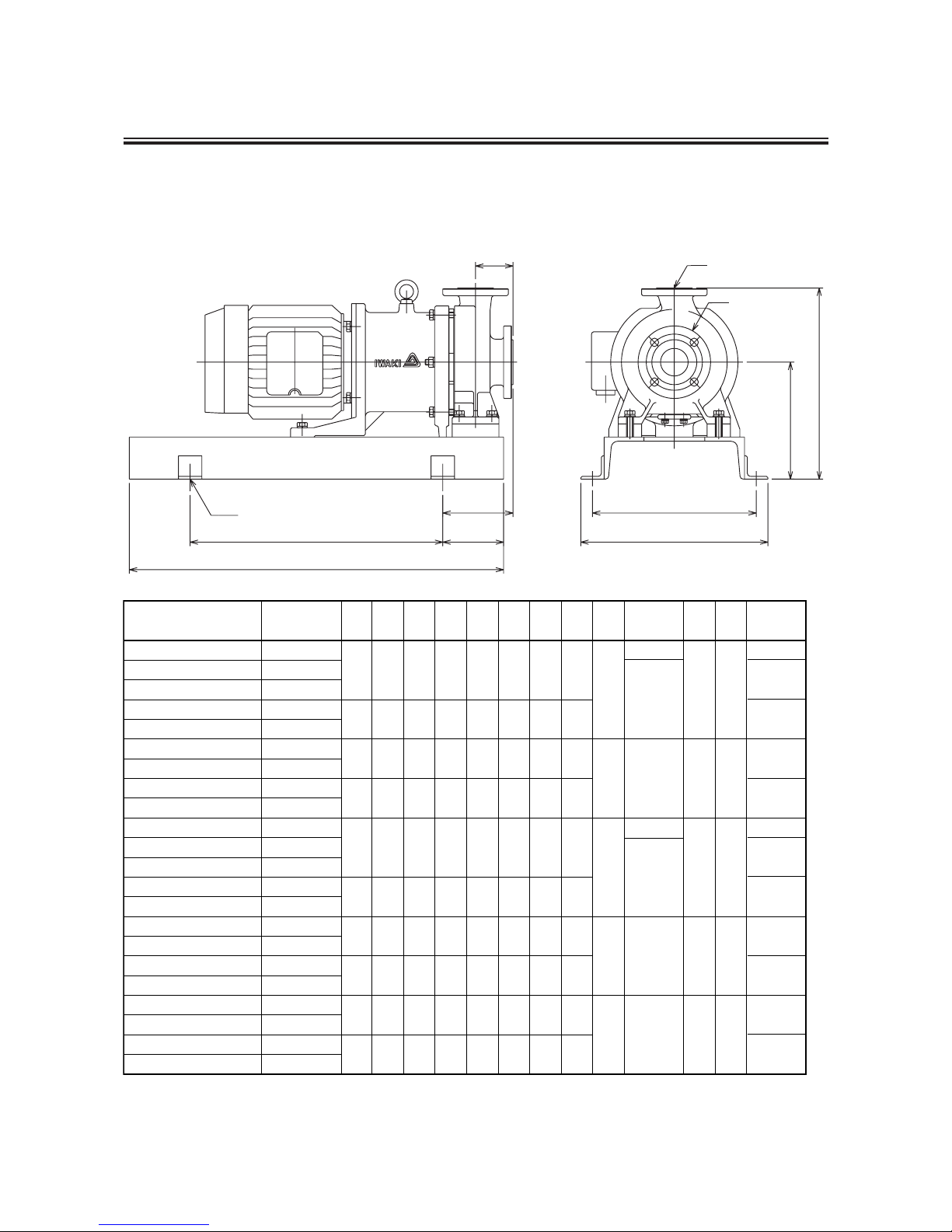
- 10 -
bb
Outer dimensions in mm
Flange mounted motor type
Model Motor W H a b c d e f g h A B
Mass
W/O Motor
(kg)
MDE32-160
MDE32-160
MDE32-160
MDE32-160
MDE32-160
MDE32-200
MDE32-200
MDE32-200
MDE32-200
MDE40-160
MDE40-160
MDE40-160
MDE40-160
MDE40-160
MDE40-200
MDE40-200
MDE40-200
MDE40-200
MDE50-160
MDE50-160
MDE50-160
MDE50-160
*1
*1
*1
*1
*1
*2
*2
*2
*2
*1
*1
*1
*1
*1
*2
*2
*2
*2
*1
*1
*1
*1
4.0kw
5.5kw
7.5kw
11kw
15kw
5.5kw
7.5kw
11kw
15kw
4.0kw
5.5kw
7.5kw
11kw
15kw
5.5kw
7.5kw
11kw
15kw
5.5kw
7.5kw
11kw
15kw
*1 Applicable to impellers with nominal diameters of 100, 110, 120, 130, 140, 150 and 160.
*2 Applicable to impellers with nominal diameters of 170, 180, 190 and 200.
400 410 350 150 540 800 130 250
480 480 430 170 600 900 150 320
400 430 350 150 540 800 130 250
480 500 430 170 600 900 150 320
400 410 350 150 540 800 130 250
480 480 430 100 600 900 150 320
400 430 350 100 540 800 130 250
480 500 430 120 600 900 150 320
400 430 350 100 540 800 130 250
480 500 430 120 600 900 150 320
80
80
80
100
100
4- 23
4- 23
4- 19
4- 23
4- 23
4- 23
4- 19
32A 50A
32A 50A
40A 65A
40A 65A
50A 80A
95
100
135
145
105
95
100
135
145
110
145
110
φ
φ
φ
φ
φ
φ
φ
B
A
W
a
H
f
h
g
(d)
(e)
c
b
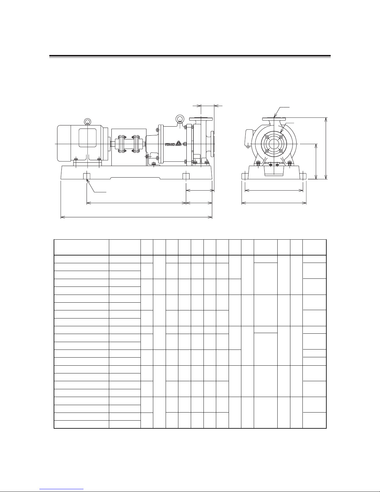
- 11 -
bb
Outer dimensions in mm
Foot mounted motor type
Model Motor W H a b c d e f g h A B
Mass
W/O Motor
(kg)
MDE32-160
MDE32-160
MDE32-160
MDE32-160
MDE32-160
MDE32-200
MDE32-200
MDE32-200
MDE32-200
MDE40-160
MDE40-160
MDE40-160
MDE40-160
MDE40-160
MDE40-200
MDE40-200
MDE40-200
MDE40-200
MDE50-160
MDE50-160
MDE50-160
MDE50-160
*1
*1
*1
*1
*1
*2
*2
*2
*2
*1
*1
*1
*1
*1
*2
*2
*2
*2
*1
*1
*1
*1
4.0kw
5.5kw
7.5kw
11kw
15kw
5.5kw
7.5kw
11kw
15kw
4.0kw
5.5kw
7.5kw
11kw
15kw
5.5kw
7.5kw
11kw
15kw
5.5kw
7.5kw
11kw
15kw
*1 Applicable to impellers with nominal diameters of 100, 110, 120, 130, 140, 150 and 160.
*2 Applicable to impellers with nominal diameters of 170, 180, 190 and 200.
390 350 170 600 915 158
450 400 190 660 1015 178
490 440 210 740 1135 198
390 350 170 600 915 158
450 400 190 660 1015 178
490 440 210 740 1135 198
450 400 190 660 1015 178
490 440 210 740 1135 198
450 400 210 660 1015 178
490 440 230 740 1135 198
450 400 210 660 1015 178
490 440 230 740 1135 198
372
400
420
372
400
420
420
212
240
240
212
240
240
240
100
100
80
80
80
4- 23
4- 23
4- 19
4- 23
4- 23
4- 23
4- 19
32A 50A
32A 50A
40A 65A
40A 65A
50A 80A
150
135
165
175
135
165
155
165
170
175
165
175
165
φ
φ
φ
φ
φ
φ
φ
h
A
B
H
f
w
a
(d)
c
(e)
b
g
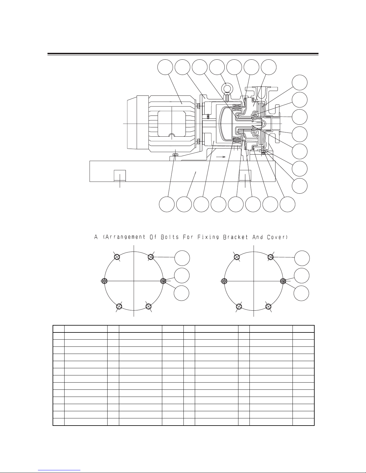
5. Names of Parts
bb
Flange mounted motor type
- 12 -
412
540
801
858
859
890
900
901.1
901.3
901.8
902
920
No.
Parts Name Q'ty Material Remarks
No.
Parts Name Q'ty Material Remarks
O Ring
Bushing
Motor
Drive Magnet Unit
Magnet Capsule Unit
Base
Eye Bolt
Hex. Head Bolt
Hex. Head Bolt
Hex. Head Bolt
Stud Bolt
Hex. Nut
1
1
1
1
1
1
1
2
2
4/6
2
2
See Note 1
See Note 1
Rare-Earth+Steel
Rare-Earth+Fluororesin
Steel
Steel
Stainless Steel
Stainless Steel
Stainless Steel
Stainless Steel
Stainless Steel
M12
M8◊20
M12◊35
M12◊65
M12
M12
100.1
122
158
159
230
314.1
314.2
330
337
370
400.1
400.2
400.4
Front Casing
Drain Plate
Rear Casing
Rear Casing Cover
Impeller
Thrust Bearing
Thrust Bearing
Bracket
Split Plate
Sleeve
Gasket Front
Gasket Rear
Gasket Drain
Fluororesin+FCD400
Steel
Fluororesin
FRP
Fluororesin+Steel
See Note 1
See Note 1
FCD400
Fluororesin+FCD400
See Note 1
PTFE
PTFE
PTFE
1
1
1
1
1
1
1
1
1
1
1
1
1
Note 1: Varies depending on pump type
801 330 370 900 159 158 337
901.3 890 858 859 540 400.2 400.1 901.1
400.4
122
412
100.1
314.1
314.2
230
A
902
920
901.8
902
920
901.8
- 13 -
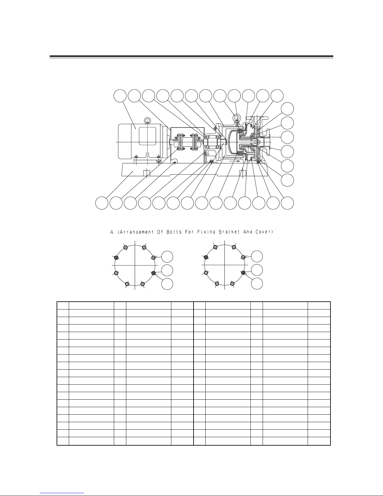
bb
Foot mounted motor type
540
551
681
800
840
858
859
890
900
901.1
901.3
901.5
901.8
902
920
932.1
932.2
No.
Parts Name Q'ty Material Remarks
No.
Parts Name Q'ty Material Remarks
Bushing
Wave Washer
Coupling Cover
Motor
Coupling
Drive Magnet Unit
Magnet Capsule Unit
Base
Eye Bolt
Hex. Head Bolt
Hex. Head Bolt
Hex. Head Bolt
Hex. Head Bolt
Stud Bolt
Hex. Nut
Retaining Ring
Retaining Ring
1
1
1
1
1
1
1
1
5
2
2
4
4/6
2
2
1
1
See Note 1
Spring Steel
Steel
Rare-Earth+Steel
Rare-Earth+Fluororesin
FC200
Steel
Stainless Steel
Stainless Steel
Stainless Steel
Stainless Steel
Stainless Steel
Stainless Steel
Steel Wire Rod
Steel Wire Rod
M12
M8◊20
M12◊20
M8◊15
M12◊65
M12
M12
100.1
122
158
159
183
212
230
314.1
314.2
321
330
337
350
370
400.1
400.2
400.4
412
Front Casing
Drain Plate
Rear Casing
Rear Casing Cover
Support
Drive Shaft
Impeller
Thrust Bearing
Thrust Bearing
Ball Bearing
Bracket
Split Plate
Bearing Housing
Sleeve
Gasket Front
Gasket Rear
Gasket Drain
O Ring
1
1
1
1
1
1
1
1
1
2
1
1
1
1
1
1
1
1
Fluororesin+FCD400
Steel
Fluororesin
FRP
Steel
Steel
Fluororesin+Steel
See Note 1
See Note 1
6208ZZ
FCD400
Fluororesin+FCD400
FC200
See Note 1
PTFE
PTFE
PTFE
See Note 1
Note 1: Varies depending on pump type
800 681 551 321 932.2 932.1 330 900 370 158 159 337
890 840 901.5 350 183 901.3 212 858 859 400.2 540 400.1 122 901.1
400.4
412
100.1
314.1
314.2
230
A
902
920
901.8
902
920
901.8
 Loading...