

IWAKI LK-A/-B TC Instruction Manual

Read this manual before use of product
IWAKI Metering pump
LK-A/-B TC
Instruction Manual

Thank you for selecting an Iwaki LK-A/-B TC metering pump. This instruction manual deals
with "Safety instructions", "Outline", "Installation", "Operation" and "Maintenance" sec-
tions. Please read through this manual carefully to ensure the optimum performance, safety
and service of your pump.
Contents
Important instructions ···································································· 1
Safety instructions ·········································································· 2
Outline 1. Unpacking & Inspection
..................................................
6
2. Product outline
.................................................................
6
3. Pump mechanism
.............................................................
7
4. Specification
.....................................................................
8
5. Model code
.......................................................................
8
6. Overview
..........................................................................
9
7. Part names (pump head)
.................................................
10
8. Precautions for use
.........................................................
11
Installation 1. Before installation
..........................................................
13
2. Installation
.....................................................................
14
3. Pipework
.........................................................................
15
4. Wiring
............................................................................
17
Operation 1. Operational precautions
..................................................
19
2. Commissioning
..............................................................
19
3. Operation
........................................................................
21
4. Flow rate adjustment
......................................................
22
5. Before/After a long period of stoppage
..........................
23
Maintenance 1. Troubleshooting
..............................................................
25
2. Maintenance & Inspection
.............................................
28
3. Spare & Wear parts
........................................................
29
4. Dismantlement & Assembly
..........................................
30
This instruction manual should be kept on hand by the end user for
quick reference.
Contact us or your nearest dealer if you have any questions.
- 1 -
Important instructions
Export restrictions
Technical information contained in this instruction manual might be treated as controlled
technology in your countries, due to agreements in international regime for export control.
Please be reminded that export license/permission could be required when this manual is
provided, due to export control regulations of your country.
Nonobservance or misapplication of “Caution” sections could lead to personal injury or property damage.
For the Safe and
Correct Handling of the Pump
●
"Safety Instruction" section deals with important details about handling of the product. Before
use, read this section carefully for the prevention of personal injury or property damage.
●
Observe the instructions accompanied with "WARNING" or "CAUTION" in this manual. These
instructions are very important for protecting users from dangerous situations.
●
The symbols on this instruction manual have the following meanings:
WARNING
Nonobservance or misapplication of “Warning” sections could lead to a serious accident which may
result in death.
CAUTION
Types of Symbols
Indicates that “Warning” or “Caution” must be exercised. Inside this triangle, a con-
crete and practical image provided as a warning or caution message is depicted.
Indicates a prohibited action or procedure. Inside or near this circle, a concrete and
practical image of the activity to be avoided is depicted.
Indicates an important action or procedure which must be performed or carried out
without fail. Failure to follow the instructions herein can lead to malfunction or
damage to the pump.
- 2 -
Safety instructions
WARNING
Turning off p ower
Prohibited
Wear protective
gear
No Remodeling
● Turn off power before service
Risk of electrical shock. Be sure to turn off power to stop the pump and related devices before service is performed.
● Wear protective clothing
Always wear protective clothing such as an eye protection, chemical resistant gloves,
a mask and a face shield during disassembly, assembly or maintenance work.
● Use strong ropes (chains) for lifting up the pump
Keep away from the pump while it is lifted up for installation. Serious injury
may result if lifting ropes (chains) break. Check lifting ropes (chains) are
strong enough before use. Observe the maximum weight of the rope (chains).
● Do not lay the pump on its side
Lubricant oil may leak from the gear box and wet the motor.
● Qualified personnel only
This product should be handled or operated by qualified personnel with a full
understanding. Any person not familiar with the product should not take part
in the operation or maintenance of this product.
● Do not modify the product
Alterations to the product carries a high degree of risk. It is not the manufacturer's responsibility for any failure or injury resulting from alterations to the pump.
● Do not use the pump in any condition other than its intended purpose
The use of the pump in any conditions other than those clearly specified may
result in failure or injury. Use this product in specified conditions only.
● Do not stand on the pump
Do not use the tank as a platform. Injury or damage may result when the tank
turns over.
● Do not get access to the inside of the drive unit during operation
Risk of personal injury. A reciprocating diaphragm/shaft may catch the finger
or hand.
● Closed-discharge operation is not allowed
Do not close a discharge line during operation. Otherwise, liquid leakage or
pump-head/motor/piping breakage may result due to overpressure.
● Starting
The pump doesn't have an ON-OFF switch. The pump starts as a power
cable is plugged in.
Caution
Prohibited
Prohibited
Caution
Prohibited
Prohibited
Caution
- 3 -
● Ventilation
Fumes or vapours can be hazardous with certain solutions. Ensure proper
ventilation at the operation site.
● Do not bring the pump close to a flammable substance
Keep the pump away from a flammable substance for the prevention of fire.
● Do not touch the pump or pipe with bare hands
Risk of burning. The surface temperature of the pump or pipe rises high along
with liquid temperature in or right after operation.
● Do not use a damaged pump
Use of a damaged pump could lead to an electric shock or death.
● Grounding
Risk of electrical shock! Always properly ground the pump. Conform to local
electric codes.
● Use specified power only
Do not apply power other than that specified on the nameplate. Otherwise,
failure or fire may result. Ensure the pump is properly grounded.
● Install an earth leakage breaker
An electrical failure of the pump may adversely affect other devices on the
same line. Purchase and install an earth leakage breaker separately.
● Do not install/store the pump:
• In a flammable/explosive/corrosive atmosphere.
• In a dusty/humid environment.
• Where ambient temperature can exceed 0-40ºC.
• In direct sunlight or wind & rain (except outdoor-use models).
CAUTION
Prohibited
Caution
Fire ban
Safety instructions
Caution
Prohibited
Grounding
Ele ct ric al
sho ck
Prohibited
- 4 -
CAUTION
Safety instructions
Caution
Caution
Prohibited
Requirement
Requirement
● Do not cover the pump with cloth
The motor temperature may build up and a fire or an electric/mechanical fail-
ure may result.
● Non-freezing
Frozen liquid may damage the pump and piping. Drain liquid before leaving it
for a long time or use measures to prevent liquid from freezing in winter.
● Do not close a suction valve in operation
Operation with a closed suction-line may damage the diaphragm.
● Depressurize piping before disassembly
Release a pressure from a discharge line before dismantling the pump or
removing piping.
● Spill precautions
Ensure protection and containment of solution in the event of plumbing or
pump damage (secondary containment).
● Foreign matter
When foreign matters enter the pump, turn off power at once and remove
them. Using the pump with foreign matters may result in failure.
● Disposal of the product
Dispose of any used or damaged product in accordance with local rules and
regulations. If necessary, consult a licensed industrial waste disposal com-
pany.
● Be sure to turn off all the related power supplies prior to any inspec-
tion/maintenance and installation works (motor fan cover).
Working on the pump with power ON, any rotating part may catch the hand,
finger, hair, or clothes, and it may result in serious injury.
Requirement
Caution

- 5 -
Outline
1. Unpacking & Inspection ........................ 6
2. Product outline ......................................6
3. Pump mechanism ................................. 7
4. Specification ......................................... 8
5. Model code ........................................... 8
6. Overview ............................................... 9
7. Part names (pump head) .................... 10
8. Precautions for use ............................. 11
- 6 -- 6 -
Outline
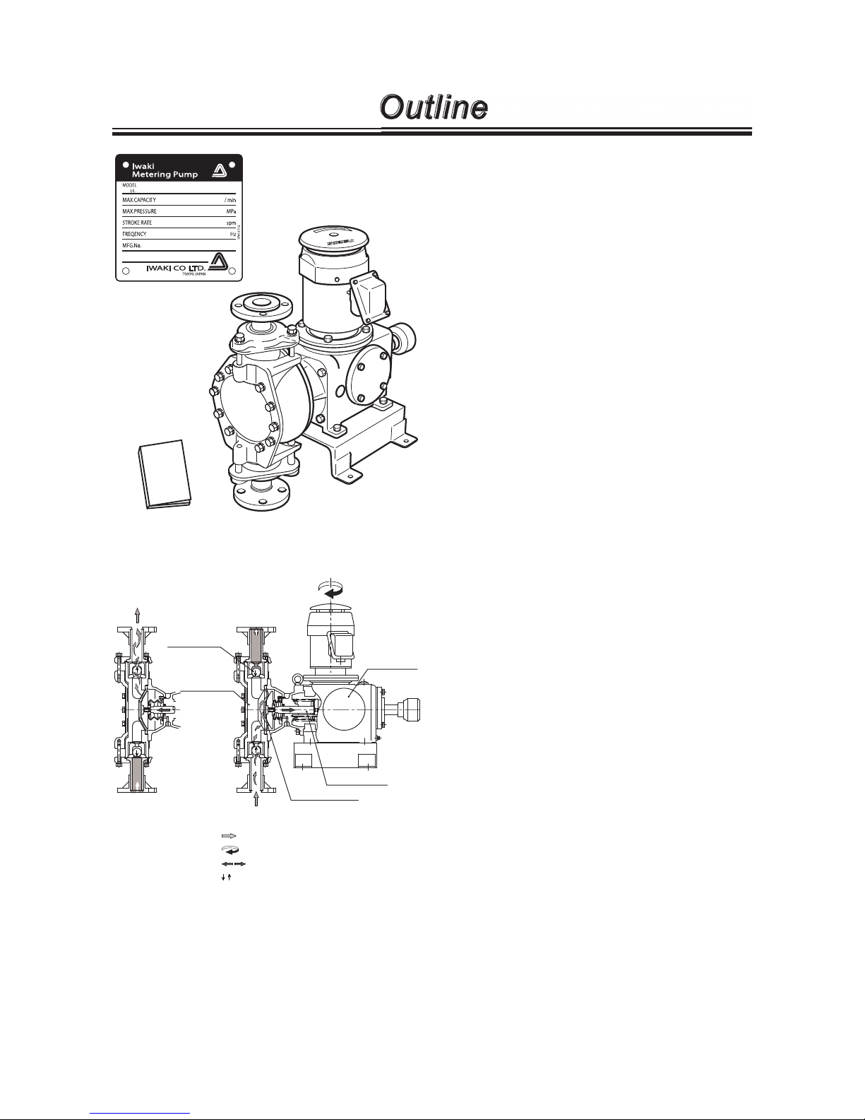
1. Unpacking & Inspection
On unpacking the product, check the following points.
If you find any problems, contact your nearest dis-
tributor.
1. Check the information on nameplate (model code,
flow rate, discharge pressure and stroke rate) to see if
the product is delivered as per order.
2. Check for transit damage, deformation, and loose
bolts.
2. Product outline
The LK-A/-B TC series is mechanically-driven dia-
phragm pump. Fluoroplastic and alumina ceramic wet
ends allow for delivery of various chemicals including
strong acid in water treatment and chemical, paper &
food industries.
■ Principle of operation
Motor rotation is transmitted to an worm wheel shaft
and then converted to the reciprocating motion of the
pump shaft. Volumetric change occurs in the pump head
as the diaphragm moves back and forth and liquid is
pumped because of the suction and discharge check
valves (ball valves).
Suction process
When the diaphragm moves back, negative pressure
in the pump head closes the discharge check valve and
open the suction check valve to take in liquid.
Discharge process
When the diaphragm moves forward, positive pressure
in the pump head opens the discharge check valve and
closes the suction check valve to deliver liquid.
: Liquid flow
: Motor rotation
: Diaphragm reciprocation
: Valve movement
Reduction
gear
Outlet
Inlet
Check valve
Pump shaft
Diaphragm
Pump head
Suction processDischarge process
IWAKI Metering Pump
LK-A/-B TC
Instruction Manual
Instruction manual
- 7 -
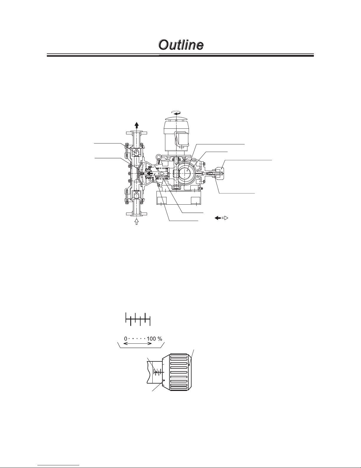
3. Pump mechanism
■ Gear unit
The gear unit of the LK-A/-B TC is spring back design consisting of a worm wheel shaft, a slider and a spring, etc.
Motor rotation is transmitted to an worm wheel shaft and then converted to reciprocating motion of the pump shaft
with the assistance of a slider and a spring.
■ Stroke length knob
Use the stroke length knob at the end of the control shaft to determine a flow rate in between 0 and 100%, changing a
slider position. See page 22 for detail.
Outline
0
1
2
9
8
0
204060
80
100
0
204060
80
100
Main scale
Sub scale
Stroke length knob
Diaphragm
Pump shaft
Spring
Control shaft
Stroke length knob
Slider
Worm wheel shaft
Ball valve
:Diaphragm reciprocation
- 8 -
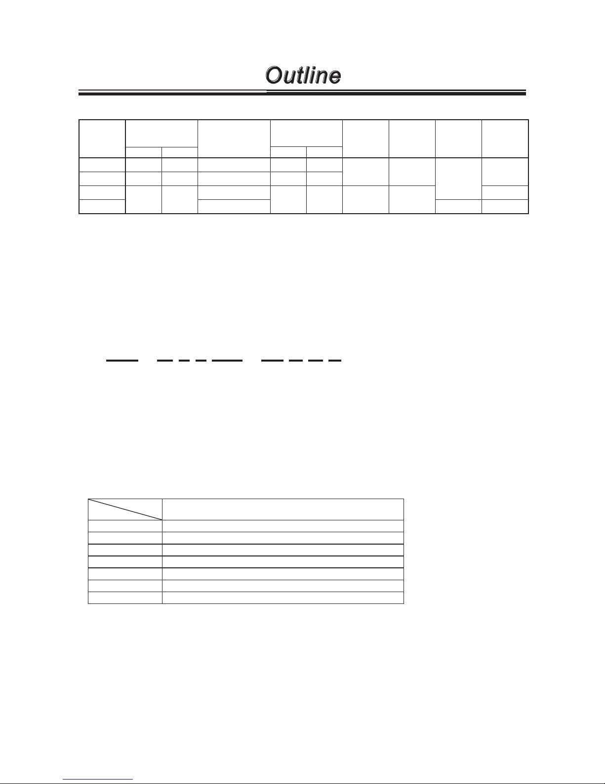
4. Specification
Model
Max flow
ℓ/min
Max discharge
pressure
MPa
Stroke rate
spm
Max stroke
length
mm
Flange
size
JIS 10K
Motor
output
kW
Approx
weight
(with
motor)kgf
50Hz 60Hz
50Hz 60Hz
LK-A55 2.8 3.3 1.0 (0.7) 48 58
10 25A
0.4
63
LK-A57 6.0 7.2 0.7 (0.5) 96 116
LK-A65
9.0 10.8
0.3 (0.2)
48 58 17.5 40A
72
LK-B65 0.5 0.75 100
* The above information is based on pumping clean water at ambient temperature.
* Metering accuracy : ±2%FS or below
* Linearity : ±3%FS or below
* Allowable liquid temperature range : 0 -50ºC
* Suction lift : 1m or below (with full stroke length)
* Allowable ambient temperature : 0-40ºC
* Figures in parenthesis are collected with 0.37kW motor.
5. Model code
LK - A 6 5 TC - 04 F E S
a b c d e f g h i
a. Series name
LK : Mechanically-driven diaphragm pump with fluoroplastic pump head and valve seat
b. Drive unit
A : 0.4kW motor B : 0.75kW motor
c. Diaphragm size
5, 6
d. Reduction gear ratio
5 : 1/30 7 : 1/15
e. Wet end materials
Part names
Wet end materials
Pump head PVC
Ball valve Highly alumina ceramics
Valve seat PVDF
O ring FKM
Valve gasket PTFE
Diaphragm PTFE+EPDM (EPDM is not a wet end.)
Allowable liquids Strong sulfuric acid
PTFE : Polytetraf luoroethylene PVDF : Polyvinylidene fluoride
EPDM : Ethylene-propylene rubber FKM : Fluorine-contained rubber
f. Motors
04 : 0.4kW 07 : 0.75kW
g. Inverter
No code : No inverter F : Inverter motor
h. Servo
No code : No servo E : Servo unit
i. Special version
No code : Standard S : Custom design
Outline
- 9 -
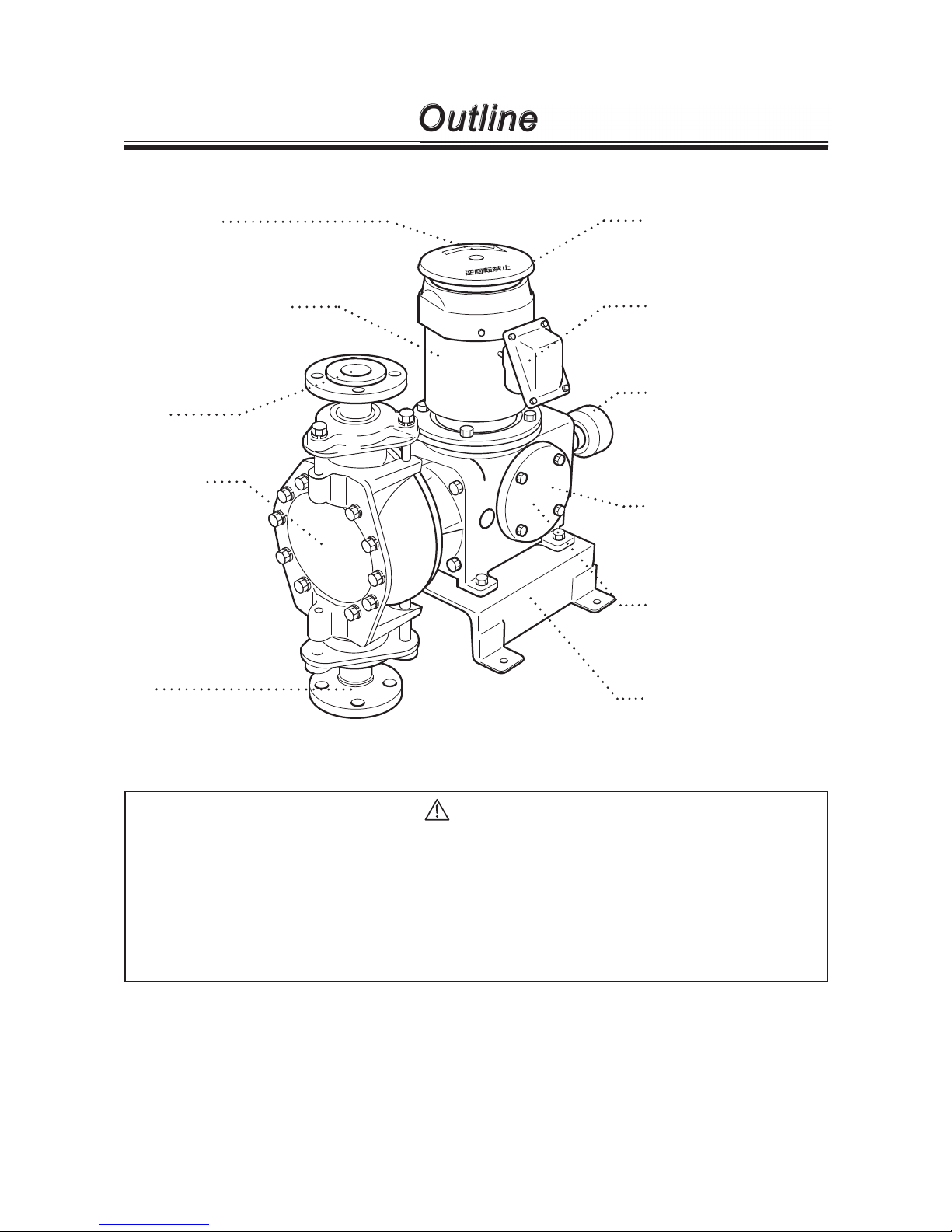
Motor nameplate
Apply the power voltage
specified on the nameplate.
Outline
"Arrow" label
The arrow indicates a rotational
direction of the motor. Make sure the
motor runs in a correct direction.
Motor fan cover
Base
Be sure to fix the base.
Reduction gear
Reduces motor rotation
speed and converts into
reciprocating motion.
Pump nameplate
Operate the pump in
accordance with specifications.
CAUTION
● Wet a cloth with tap water and wring it out for cleaning the pump. Use a neutral deter-
gent for greasy dirt and then rub with a dry cloth. Do not wipe nameplates, labels or
pump body with any solvent.
● Risk of fire or electric shock. Be sure to turn off all the related power supplies prior to
any inspection/maintenance and installation works. Keep the terminal box, motor fan
cover and electric wiring dry.
6. Overview
Stroke length knob
Determines liquid volume
per shot in between 0 and
100%.
Outlet
Inlet
Pump head
Tightening torque indication label
Observe the indication
when tightening torque.

- 10 -
Outline
7. Part names (pump head)
LK-A55/-A57 TC
No. Names Q'ty
1 Pump head 1
2 Valve 2
3 Valve guide 2
4 Valve seat 2
5 Valve gasket 2
7 O ring 2
20 Hex head bolt 8
21 Spring washer 8
29 Reinforcing plate 1
30 Diaphragm 1
31 Retainer 1
50 Nut 2
51 Union 2
54 Flange 2
55 Flange adapter 2
LK-A65/-B65 TC
No. Names Q'ty
1 Pump head 1
2 Valve 2
3 Valve guide 2
4 Valve seat 2
7 O ring 2
20 Hex head bolt 10
21 Spring washer 10
26 Insert bumper 2
29 Reinforcing plate 1
30 Diaphragm 1
31 Retainer plate 1
32 Hex head bolt 6
55 Setting flange 1
73 Port 2
74 Flange 2
82 Spring washer 6
83 Rear seat 1
84 Flange adapter 1
32
82
30
3
83
31
7
3
2
4
20
21
29
1
2
4
7
84
74
55
73
55
73
74
84
26
7
3
2
4
5
1
29
30
31
21
5
20
3
2
4
7
50
51
54
55
55
54
50
51
Flange unit
(discharge side)
Flange unit
(discharge side)
Flange unit
(suction side)
Flange unit
(suction side)
 Loading...