

IWAKI IX-C060 S6, IX-C060 TC/TE, IX-C150 S6, IX-C150 TC/TE Instruction Manual
IX-C series (North America)
Safety instructions
Overview Installation Operation Maintenance Specication
Instruction manual
Thank you for choosing our product.
Please read through this instruction manual before use.
This instruction manual describes important precautions and instructions for the product. Always keep it on hand for quick reference.
©2015 IWAKI CO., LTD.
Order conrmation
Open the package and check that the product conforms to your order. If any problem or
inconsistency is found, immediately contact your distributor.
a. Check if the delivery is correct.
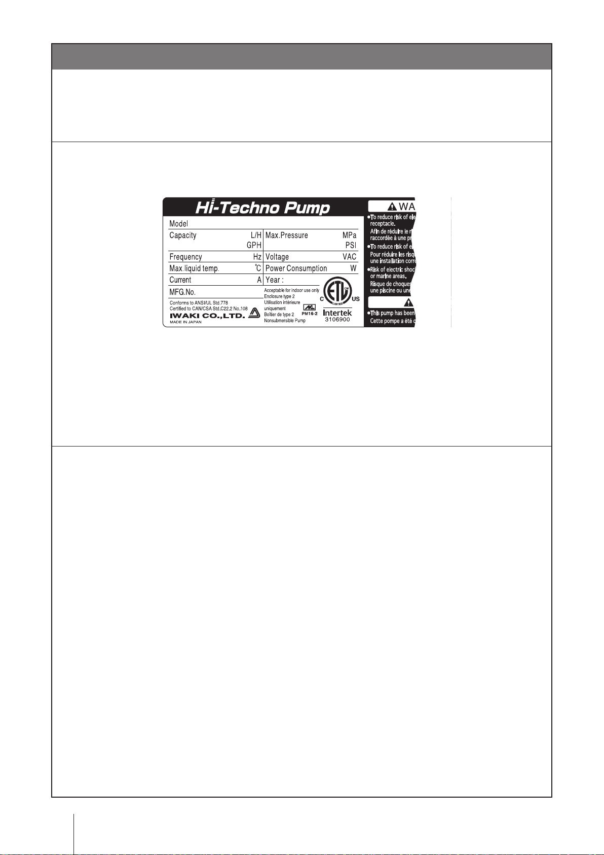
Check the nameplate to see if the information such as model codes, discharge capacity and discharge
pressure are as ordered.
b. Check if the delivery is damaged or deformed.
Check for transit damage and loose bolts.
Order conrmation
2

Contents
Order conrmation ..........................................................................................................................................2
Safety instructions .................................................................... 6
Warning ..........................................................................................................................................................7
Caution ...........................................................................................................................................................8
Precautions for use ....................................................................................................................................10
Overview ...................................................................................12
Introduction .................................................................................................................................................12
Pump structure & Operating principle ......................................................................................................12
Features ...................................................................................................................................................13
Operational function ...................................................................................................................................13
Manual mode ...........................................................................................................................................13
EXT mode ................................................................................................................................................14
Analogue proportional control .............................................................................................................14
Pulse control .......................................................................................................................................16
Batch control .......................................................................................................................................16
Interval batch control ...........................................................................................................................18
AUX function ............................................................................................................................................18
Priming function .......................................................................................................................................18
STOP functions ........................................................................................................................................19
STOP function .....................................................................................................................................19
Pre-STOP function ..............................................................................................................................19
Analogue output function .........................................................................................................................19
Protective functions ..................................................................................................................................20
Interlock function .................................................................................................................................20
Diaphragm rupture detection ..............................................................................................................20
Pressure overload/Failed rotation control detection ...........................................................................20
Alarm output function ..........................................................................................................................21
Other functions .........................................................................................................................................21
Suction speed setting ..........................................................................................................................21
Maximum ow rate setting ..................................................................................................................21
Diaphragm position adjustment ..........................................................................................................21
Anti chattering programming ...............................................................................................................21
Output logic setting .............................................................................................................................21
Flow unit setting ..................................................................................................................................21
Language setting ................................................................................................................................21
Keypad lock .........................................................................................................................................21
Default setting .....................................................................................................................................21
Part names ...................................................................................................................................................22
Pump ........................................................................................................................................................22
Contents
3

Operational panel .....................................................................................................................................23
Basic displays & Pump states .............................................................................................................24
Identication codes ....................................................................................................................................25
Pump ........................................................................................................................................................25
Installation .............................................................................. 26
Pump mounting ...........................................................................................................................................26
Pipework ......................................................................................................................................................27
Piping layout ........................................................................................................................................27
Drain port (Vent hole) .................................................................................................................................28
Wiring ...........................................................................................................................................................29
End terminals ...........................................................................................................................................29
Power voltage/Earthing ............................................................................................................................30
Signal wire connection .............................................................................................................................31
EXT IN ................................................................................................................................................32
STOP IN ..............................................................................................................................................32
AUX IN/Analog OUT ...........................................................................................................................33
Alarm OUT (DIN connector) ................................................................................................................33
Operation ................................................................................. 34
Before operation .........................................................................................................................................34
Points to be checked ................................................................................................................................34
Retightening of pump head xing bolts ....................................................................................................34
Commissioning .........................................................................................................................................35
Before a long period of stoppage (One month or more) ..........................................................................35
Perform a calibration ..................................................................................................................................36
Calibration process ..................................................................................................................................37
Operation programming .............................................................................................................................39
Programming ow ....................................................................................................................................40
Menu screen ............................................................................................................................................41
EXT mode selection ............................................................................................................................42
Calibration ...........................................................................................................................................44
Signal input setting ..............................................................................................................................45
Analogue output setting ......................................................................................................................46
Alarm output setting (OUT 1) <Mechanical relay> ..............................................................................47
Alarm output setting (OUT 2) <PhotoMOS relay> ..............................................................................49
Data logging ........................................................................................................................................50
Programming of other functions ..........................................................................................................51
Operation .....................................................................................................................................................54
Manual operation .....................................................................................................................................54
EXT operation ..........................................................................................................................................54
AUX function ............................................................................................................................................55
Priming function .......................................................................................................................................55
Keypad lock ..............................................................................................................................................56
4
Contents

Keypad lock activation ........................................................................................................................56
Keypad lock release ............................................................................................................................56
Emergency stop ..................................................................................................................................56
Maintenance .............................................................................57
Troubleshooting ..........................................................................................................................................58
Pump ...................................................................................................................................................58
Error messages ...........................................................................................................................................59
Inspection ....................................................................................................................................................59
Daily inspection ........................................................................................................................................59
Periodic inspection ...................................................................................................................................59
Wear part replacement ...............................................................................................................................60
Wear part list ............................................................................................................................................60
Before replacement ..................................................................................................................................62
Valve set replacement ..............................................................................................................................62
Diaphragm replacement ...........................................................................................................................63
Exploded view .............................................................................................................................................67
Pump head, Drive unit & Control unit .......................................................................................................67
Pump head ...............................................................................................................................................68
IX-C150 TC N ......................................................................................................................................68
IX-C150 TC FA ....................................................................................................................................69
IX-C150 S6 N ......................................................................................................................................70
IX-C150 S6 FA ....................................................................................................................................71
IX-C060 TC N .....................................................................................................................................72
IX-C060 TC FA ....................................................................................................................................73
IX-C060 S6 N ......................................................................................................................................74
IX-C060 S6 FA ....................................................................................................................................75
Specications/Outer dimensions ..............................................................................................................76
Specications ...........................................................................................................................................76
Pump ...................................................................................................................................................76
Power cable ........................................................................................................................................76
Body colour .........................................................................................................................................76
Control unit ..........................................................................................................................................77
Outer dimensions .....................................................................................................................................78
IX-C060/-C150 TC/TE N-TB ...............................................................................................................78
IX-C060/-C150 TC/TE FA-TB .............................................................................................................79
IX-C060/-C150 TC/TE N-RF ...............................................................................................................80
IX-C060/-C150 TC/TE FA-RF .............................................................................................................81
IX-C060/-C150 S6 N-TB .....................................................................................................................82
IX-C060/-C150 S6 FA-TB ...................................................................................................................83
IX-C060/-C150 S6 N-RF .....................................................................................................................84
IX-C060/-C150 S6 FA-RF ...................................................................................................................85
Contents
5

Safety instructions
Read through this section before use. This section describes important
information for you to prevent personal injury or property damage.
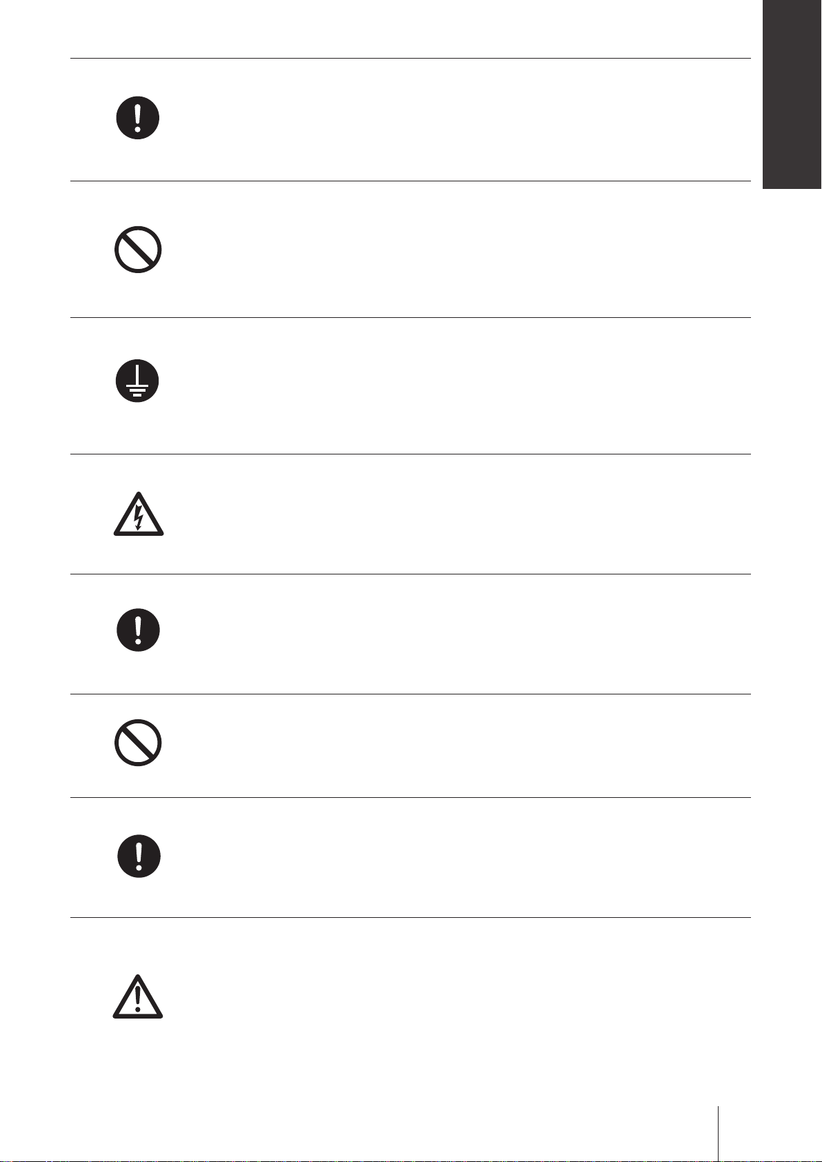
■ Symbols
In this instruction manual, the degree of risk caused by incorrect use is noted with the follow-
ing symbols. Please pay attention to the information associated with the symbols.
Indicates mishandling could lead to a fatal or serious injury
WARNING
CAUTION
A symbol accompanies each precaution, suggesting the use of "Caution", "Prohibited actions"
and specic "Requirement".
accident.
Indicates mishandling could lead to personal injury or prop-
erty damage.
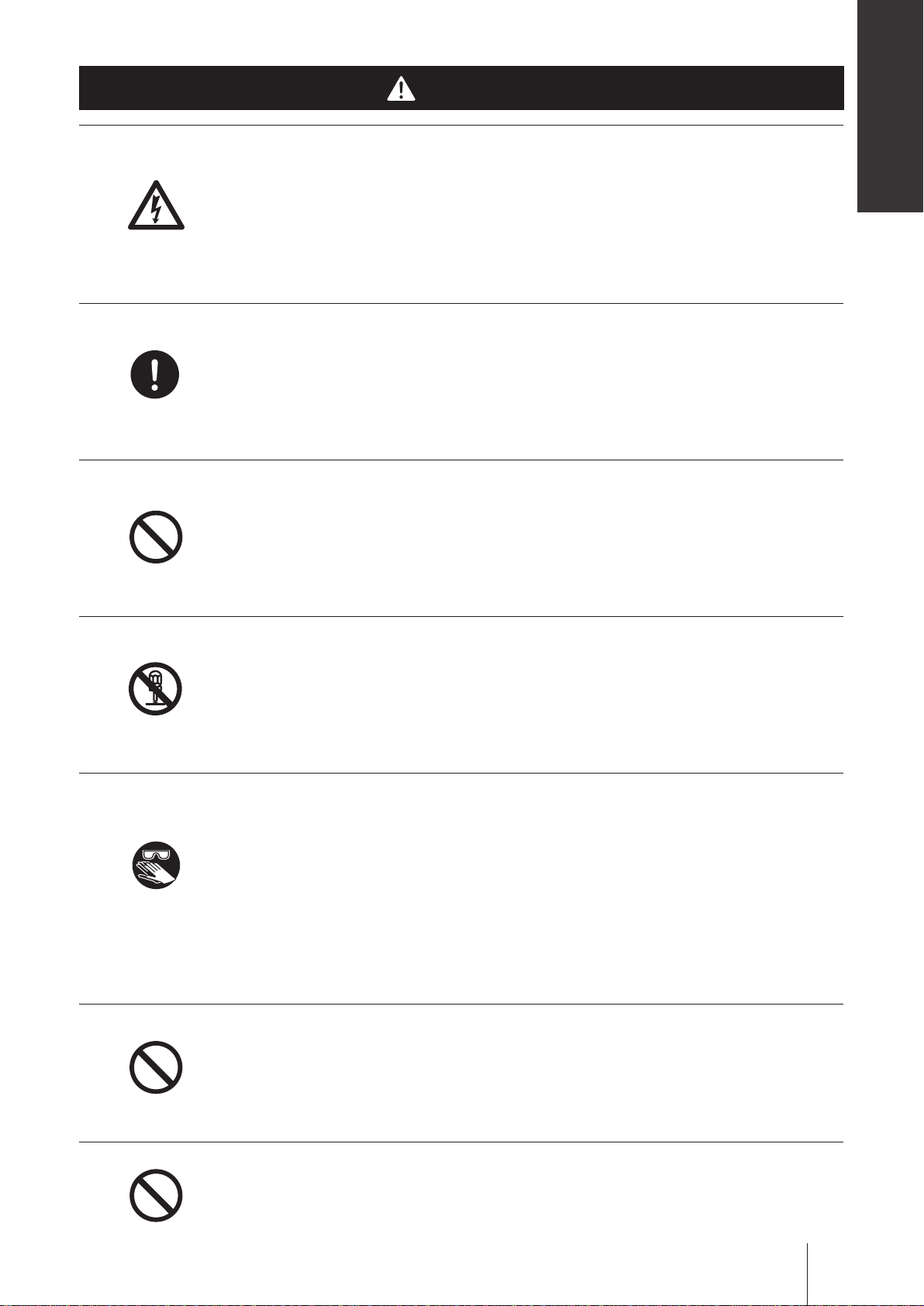
Caution marks Prohibition mark Requirement mark
Caution
Electrical
shock
Prohibition
Do not remodel
Requirement
Wear
protectors
Earthing
Export Restrictions
Technical information contained in this instruction manual might be treated as controlled tech-
nology in your countries, due to agreements in international regime for export control.
Please be reminded that export license/permission could be required when this manual is
provided, due to export control regulations of your country.
Safety instructions
6
Electrical
shock
Requirement
Safety instructions
WARNING
Turn off power before service
Risk of electrical shock. Be sure to turn off power to stop the pump and
related devices before service is performed.
Couper l’alimentation électrique de la pompe avant intervention
Intervenir sur la pompe sans avoir au préalablement coupé l’alimentation
électrique peut déclencher des décharges électriques. Avant d’entreprendre
n’importe quel type d’intervention, veillez à mettre la pompe et tout dispositif
connexe hors tension à l’aide de l’interrupteur prévu à cet effet.
Stop operation
If you notice any abnormal or dangerous conditions, suspend operation
immediately and inspect/solve problems.
Arrêter le fonctionnement
Si vous détectez une anomalie ou des signes suspects et inhabituels
pendant le fonctionnement, interrompez immédiatement les opérations et
inspectez, résolvez les problèmes.
Prohibition
Do not remodel
Wear
protectors
Do not use the pump in any condition other than its intended purpose
The use of the pump in any conditions other than those clearly specied
may result in failure or injury. Use this product in specied conditions only.
Se conformer uniquement aux applications prévues
La pompe doit être utilisée conformément à l’usage pour lequel elle a été
prévue et dans le respect de ses caractéristiques techniques. Toute utilisa-
tion non conforme peut entraîner un incident ou endommager le dispositif.
Do not modify the pump
Alterations to the pump carries a high degree of risk. It is not the manufacturer's
responsibility for any failure or injury resulting from alterations to the pump.
Ne pas modier la pompe
Ne jamais modier une pompe sous peine de causer un incident grave.
Iwaki ne pourra en aucun cas être tenu responsable d’un incident ou de
dégâts survenus à la suite d’une modication du dispositif.
Wear protective clothing
Always wear protective clothing such as an eye protection, chemical re-
sistant gloves, a mask and a face shield during disassembly, assembly or
maintenance work. The specic solution will dictate the degree of protec-
tion. Refer to MSDS precautions from the solution supplier.
Porter un équipement de protection
Toujours porter un équipement de protection (lunettes, gants ré-
sistants aux produits chimiques, masque, casque) durant le démontage,
l’assemblage et la maintenance.
Le travail effectué dictera le degré de protection. Référez-vous au MSDS
de la solution proposée par le fournisseur.
Prohibition
Prohibition
Do not damage the power cable
Do not pull, knot, or crush the power cable. Damage to the power cable
could lead to a re or electrical shock if cut or broken.
Ne pas endommager le câble électrique
Ne pas tirer ou faire un nœud avec le câble électrique. Endommager un
câble électrique pout provoquer une incendie ou une décharge électrique.
Do not operate the pump in a ammable atmosphere
Do not place explosive or ammable material near the pump.
Ne pas utiliser la pompe dans une atmosphère explosive
Pour votre sécurité, du matériel dangereux ou inammable ne doit pas
être placé près de la pompe.
WARNING
7

Risk of electric shock
This pump is supplied with a grounding conductor and grounding-type
attachment plug. To reduce the risk of electric shock, be certain that it is
connected only to a properly grounded, grounding type receptacle.
Electrical
shock
Requirement
Prohibition
Risque de choc électrique
La pompe est fournie avec un conducteur pour mise à la terre et une prise
courant. An de réduire le risque de choc électrique, veillez à ce que la
terre soit correctement raccordée.
CAUTION
Qualied personnel only
The pump should be handled or operated by qualied personnel with a
full understanding of the pump. Any person not familiar with the product
should not take part in the operation or maintenance of the pump.
Opérateur qualié uniquement
La pompe doit être manipulée ou utilisée par du personnel qualié con-
naissant parfaitement la pompe. Tout autre personne étrangère ne doit
pas prendre part à l’utilisation ou à la maintenance de la pompe.
Use specied power only
Do not apply power other than that specied on the nameplate. Otherwise,
failure or re may result. Ensure the pump is properly grounded.
Utilisez une tension appropriée uniquement
Ne pas appliquer une autre tension que celle spéciée sur la plaque sig-
nalétique sinon, il peut en résulter une panne ou une incendie. Assurezvous également de la mise à la terre de la pompe.
Prohibition
Caution
Prohibition
Keep electric parts and wiring dry
Risk of re or electric shock. Install the pump where it can be kept dry.
Ne mouillez pas les parties électriques ou les câbles
Risque d’incendie ou de décharge électrique. Installez la pompe dans un
endroit sec.
Ventilation
Fumes or vapors can be hazardous with certain solutions. Ensure proper
ventilation at the operation site.
Ventilation
Manipuler un produit toxique ou odorant peut provoquer une intoxication.
Prévoyez une ventilation sufsante à l’endroit de la manipulation.
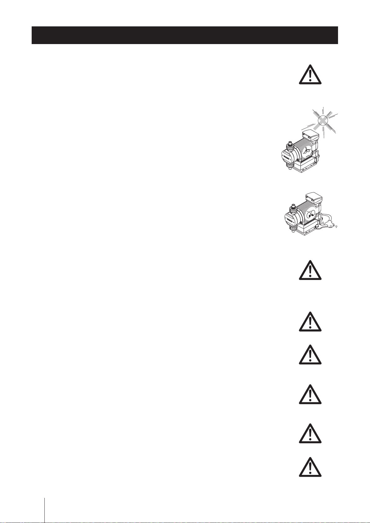
Do not install or store the pump:
• In a ammable atmosphere.
• In a dusty/humid environment.
• Where ambient temperature can exceed 0-50ºC (32-122°F).
• In direct sunlight or wind & rain.
N’installez ou ne stockez pas la pompe dans les endroits suivantes:
• Dans une atmosphère inammable
• Dans un endroit poussiéreux ou humide.
• Dans une place où la température n’est pas comprise entre 0 et 50 °C.
• Directement sous le soleil, le vent ou la pluie.
8
This pump has been evaluated for use with water only.
Cette pompe a été testée uniquement avec de l'eau.
Caution
CAUTION
Spill precautions
Ensure protection and containment of solution in the event of plumbing or
pump damage (secondary containment).
Safety instructions
Requirement
Prohibition
Earthing
Electrical
shock
Déversement accidentel
Prenez des mesures protectrices contre tout incident résultant d’un débit
trop important de la pompe ou d’une casse de tuyauterie.
Do not use the pump in a wet location
The pump is not waterproof. Use of the pump in wet or extremely humid
locations could lead to electric shock or short circuit.
N’utilisez pas la pompe sous l’eau
La pompe n’est pas complètement étanche. Utiliser la pompe dans l’eau
ou dans un endroit très humide peut créer une décharge électrique ou un
court-circuit.
Grounding
Risk of electrical shock! Always properly ground the pump. Conform to lo-
cal electric codes.
Mise à la terre
Veillez à ne pas faire fonctionner la pompe sans avoir au préalable prévu
une mise à la terre. Celle-ci permettra d’éviter d’éventuelles décharges
électriques. Vériez que le câble de mise à la terre est bien branché.
Install a GFCI (earth leakage breaker)
An electrical failure of the pump may adversely affect other devices on the
same line. Purchase and install a GFCI (earth leakage breaker) separately.
Détecteur de fuites à la terre
Un problème électrique peut affecter défavorablement le dispositif. Achet-
ez et installez un détecteur de fuites à la terre.
Requirement
Prohibition
Requirement
Preventative maintenance
Follow instructions in this manual for replacement of wear parts. Do not
disassemble the pump beyond the extent of the instructions.
Remplacement des pièces usées
Suivez les instructions de ce manuel pour remplacer les pièces usées. Ne
démontez pas la pompe au-delà des instructions.
Do not use a damaged pump
Use of a damaged pump could lead to an electric shock or death.
N’utilisez pas une pompe endommagée
Utiliser une pompe endommagée peut provoquer une décharge électrique
ou la mort.
Disposal of a used pump
Dispose of any used or damaged pump in accordance with local rules and
regulations. If necessary, consult a licensed industrial waste disposal company.
Elimination des pompes usées
Elle doit se faire en conformité avec les règles locales en vigueur (consult-
ez une entreprise certiée et spécialisée).
Check pump head bolts
Liquid may leak if any of the M8/M5 pump head bolts become loose. Remove
the bolt cover and tighten the bolts diagonally and evenly by 12N•m (IX-C150)
or 3.5N•m (IX-C060) before initial operation and at regular intervals.
Caution
Serrez la tête de pompe
Il pourrait y avoir une fuite de liquide si les 8 boulons M8/M5 du corps de
pompe ne sont pas bien serrés. Enlevez le cache boulon et resserrez les
boulons diagonalement et uniformément (12N•m: IX-C150, 3.5N•m: IXC060) avant la première utilisation et à intervalles réguliers.
CAUTION
9
Precautions for use
• Electrical work should be performed by a qualified electrician. Otherwise,
personal injury or property damage could result.
Le raccordement électrique de la pompe doit être effectué par du person-
nel qualié sinon, il pourrait y avoir un dommage corporel ou incorporel.
• Do not install the pump:
–In a ammable atmosphere.
–In a dusty/humid place.
–In direct sunlight or wind & rain.
–Where ambient temperature can exceed 0-50ºC (32-122°F).
Ne pas installer la pompe dans les endroits suivants:
–Dans une atmosphère inammable
–Dans une atmosphère poussiéreuse ou humide.
–Sous les rayonnements du soleil, dans le vent ou sous la pluie.
–La température ambiante doit être comprise entre 0 et 50°C.
• Select a level location, free from vibration, that won't hold liquid. Anchor
the pump with four M8 bolts so it doesn't vibrate. If the pump is not in-
stalled level, output may be affected.
Choisissez un endroit où il n’y a pas de vibrations et où le liquide peut
s’évacuer. Fixez la pompe à l’aide de visses M8 de façon à ne pas avoir de
vibrations. Si la pompe est inclinée, le débit peut être réduit.
• When two or more pumps are installed together, vibration may be signifi-
cant, resulting in poor performance or failure. Select a solid foundation
(concrete) and fasten anchor bolts securely to prevent vibration during
operation.
Caution
Si plusieurs pompes sont installées ensemble, elles interagissent et les
vibrations peuvent devenir importantes, ce qui engendre des performances
médiocres ou des ratures. Choisissez un endroit solide et xez les boulons
correctement pour évitez les vibrations pendant le fonctionnement.
• Allow sufficient space around the pump for easy access and maintenance.
Prévoyez de l’espace autour de la pompe pour faciliter l'accès et la mainte-
nance.
• Install the pump as close to the supply tank as possible.
Installez la pompe le plus près possible du tank de produit.
• When handling liquids that generate gas bubbles (sodium hypochlorite or
hydrazine solution), install the pump in a cool and dark place. Flooded suc-
tion installation is strongly recommended.
Installez la pompe dans une place froide à l’abri du soleil lorsqu’il s’agit
du dosage de produits dégazant tels que l’hypochlorite de sodium ou
l’hydrazine. Mettre la pompe en charge est vivement recommandé.
• The suction line I.D. should be equal to or wider than the I.D. of the pump.
La ligne d’aspiration doit être plus large que l’entrée de la pompe.
• Build up a flooded suction system for the viscous liquid delivery of
300mPa•S or more.
Caution
Caution
Caution
Caution
Caution
Pour les liquides ayant une viscosité supérieure ou égale à 300 mPa.s il
faut mettre la pompe en charge.
Precautions for use
10
Caution
• Use measures to keep the pump connections free from stress. Weight and
thermal expansion/contraction of the piping can stress connection points.
Safety instructions
La pompe ne doit pas être soumise à des effets éventuels de dilation ou de
contraction du pipe dus à un stress thermique.
• Overload protection will stop pump operation when discharge pressures
reach 1.3 to 2 times higher than the pump maximum. If the discharge line
cannot conservatively handle the maximum pressure, use a relief valve to
safely depressurize the discharge line.
Un dispositif de protection en cas de surcharge doit pouvoir arrêter le dos-
age quand la pression au refoulement s’élève de 1,3 à 2 fois le maximum
admis. Installez une vanne de sécurité pour relâcher la pression de la ligne
de refoulement si la ligne de refoulement ne peut pas supporter de haute
pression.
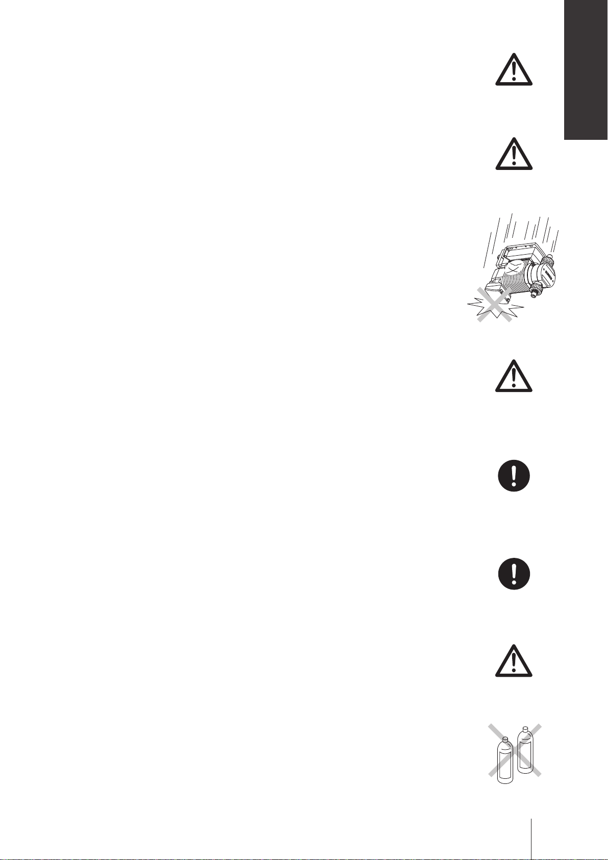
• Use care handling the pump. Do not drop. An impact may affect pump
performance. Do not use a pump that has been damaged to avoid the risk
of electrical damage or shock.
Veillez à ne pas laisser tomber la pompe sur le sol. Un impact important
pourrait réduire les performances de la pompe. Ne pas utiliser une pompe
endommagée sinon il pourrait y avoir un courant de fuite ou une décharge
électrique.
• The pump has a rating of IP65 equivalent, but is not waterproof. Do not op-
erate the pump while wet with solution or water. Failure or injury may result.
Immediately dry off the pump if it gets wet.
Caution
Caution
Le pompe est IP65 équivalent mais n’est pas complètement étanche. Ne
pas laisser la pompe couverte de liquide pompé ou sous la pluie. Il pour-
rait y avoir des ratés ou préjudices. Si la pompe a été mouillée, sechez-la
directement.
• Do not close discharge line during operation. Solution may leak or piping
may break. Install a relief valve to ensure safety and prevent damaged
plumbing.
Ne fermez pas la ligne de refoulement lorsque la pompe est en fonctionne-
ment sinon il pourrait y avoir des fuites de liquide ou la tuyauterie pourrait
céder. Installez une soupape de sécurité pour des raisons de sécurité et
pour éviter tout dommage de la tuyauterie.
• Solution in the discharge line may be under pressure. Release the pres-
sure from the discharge line before disconnecting plumbing or disassembly
of the pump to avoid solution spray.
Le liquide au refoulement peut être sous pression. Relâchez la pression
du refoulement avant de démonter la pompe ou d’enlevez le tubage pour
éviter tout jet de liquide.
• Wear protective clothing when handling or working with pumps. Consult
solution MSDS for appropriate precautions. Do not come into contact with
residual solution.
Portez un équipement de sécurité lorsque vous manipulez la pompe. Consultez le MSDS pour utilisez les précautions appropriées. Evitez tout con-
tact avec le liquide chimique.
Caution
Requirement
Requirement
Caution
• Do not clean the pump or nameplate with a solvent such as benzine or
thinner. This may discolour the pump or erase printing. Use a dry or damp
cloth or a neutral detergent.
Ne nettoyez pas la pompe ou la plaque signalétique à l’aide d’un solvant
comme le benzène ou le white spirit. Cela pourrait décolorer la pompe ou
effacer l’impression. Utilisez un tissu sec ou mouillé avec de l’eau ou un
détergent neutre.
Benzine
Precautions for use
Thinner
11
Overview
Pump characteristics, features and part names are described in this
section.
Introduction
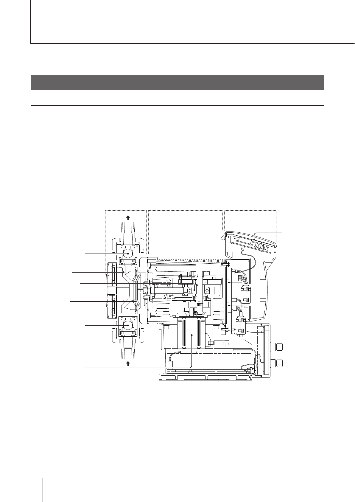
Pump structure & Operating principle
The IX series are diaphragm pumps with a brushless DC (BLDC) motor and feature a high turndown ratio &
automatic controls.
Principle of operation
In the IX series design, a BLDC motor rotation controls the ow rate.
Motor rotation is transmitted to an eccentric cam through a reduction gear and then converted to reciprocating
motion. Volumetric change occurs in the pump chamber as the diaphragm moves back and forth and liquid is
pumped because of the suction and discharge check valves. Discharge speed changes the ow rate while the
suction speed remains the same at any ow rate.
Control unitPump head Drive unit
Pump head valve
(discharge side)
Pump head
Eccentric cam
Diaphragm
Pump head valve
(suction side)
Brushless motor
OUT
Keypads
IN
12
Introduction
Features
● High turndown ratio
Use of a BLDC control motor enables accurate control with a wide turndown ratio.
● High repeatability
Highly-efcient valve design and accurate discharge-/suction-speed controls assure the high repeatability of
chemical dosing (±1%).
● Energy-saving design
Use of helical gears and an assist spring reduces power consumption by 70% compared to our existing me-
tering pump designs (spring back).
● Automatic control
The IX can automatically run along with analogue-, pulse-, batch- or interval batch-operation programming.
● Multivoltage operation
The IX series can be used in all countries thanks to the universal power voltage (100-240VAC).
● Safety design
A diaphragm rupture detection ensures user safety and a pressure overload detection protects the pump and
pipework from an accidental discharge line pressure rise.
● Ingress protection rating of IP65
Overview
Operational functions
Manual mode
Run/stop the pump by key operation. The ow rate can be changed by the up and the down keys at any time
during operation or stop. The operation LED lights in green colour during operation. See page 54 for detail.
Key operation
(Push key)
Run
Pump operation
Stop
Run
Stop
Operational functions
13
EXT mode
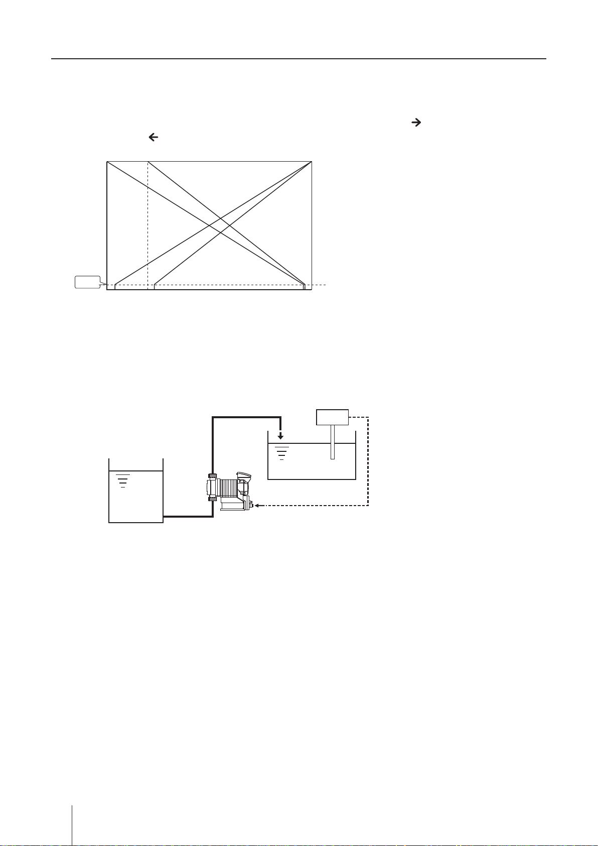
■ Analogue proportional control
ANA. P (analogue preset) programming (see page 42 & 54)
Select a proportional control pattern. 4 - 20mA, 20 - 4mA, 0 - 20mA and 20 - 0mA are available. During opera-
tion, the display shows the current ow rate. To show the current value, push the key. To return to the ow
rate display, push the key.
Max
b
d
Flow rate
[L/H]
c
a
Min
0 4 20
4-20mA analogue signal
Example of use: pH control in a water treatment system
Supply tank
pH meter
Electrode
The left graph shows the flow rate at each
pattern.
a. 4 - 20mA
b. 20 - 4mA
c. 0 - 20mA
d. 20 - 0mA
* The ow rate falls to 0mL/H if the pump runs
beneath the minimum rate.
* The pump does not run over the maximum ow
rate at any current value.
4-20mA signal
Pump
14
Operational functions
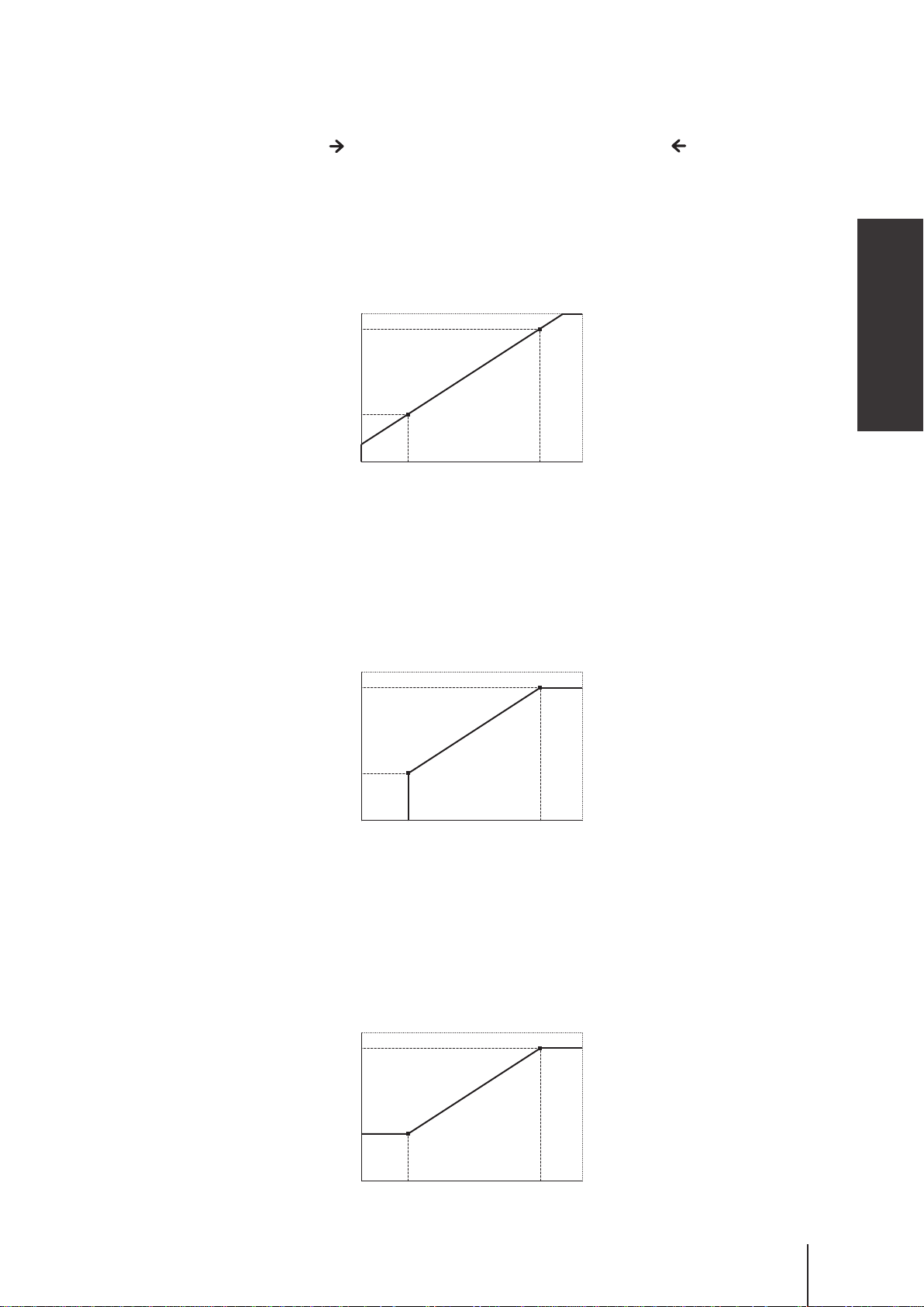
ANA. V (analogue variable) programming (see page 42 & 54)
The pump increases/decreases a stroke/ow rate in proportion to 0-20mA. Determine the operational behav-
iour by programming two set points and choosing one of the LINEAR, BOX and LIMIT patterns.
To show the current value, push the key. To return to the ow rate display, push the key.
<LINEAR>
A stroke/ow rate changes with a current value by a programmed line.
Condition:
Set Point 1 (SP.1) = Ampere : 6mA, Flow rate : 45L/H
Set Point 2 (SP.2) = Ampere : 17mA, Flow rate : 127L/H
150L/H
127L/H
SP.2
Overview
45L/H
0 6
SP.1
17
20mA
<BOX>
A stroke/ow rate changes with a current value by a programmed line. The rate does not exceed the Set Point
2 but then falls to 0 before the Set Point 1.
Condition:
Set Point 1 (SP.1) = Ampere : 6mA, Flow rate : 45L/H
Set Point 2 (SP.2) = Ampere : 17mA, Flow rate : 127L/H
150L/H
127L/H
45L/H
SP.1
0 6
17
SP.2
20mA
<LI M IT>
A stroke/ow rate changes with a current value by a programmed line. The rate does not falls below the Set
Point 1 or exceed the Set Point 2.
Condition:
Set Point 1 (SP.1) = Ampere : 6mA, Flow rate : 45L/H
Set Point 2 (SP.2) = Ampere : 17mA, Flow rate : 127L/H
150L/H
127L/H
45L/H
SP.1
0 6
17
SP.2
20mA
Operational functions
15
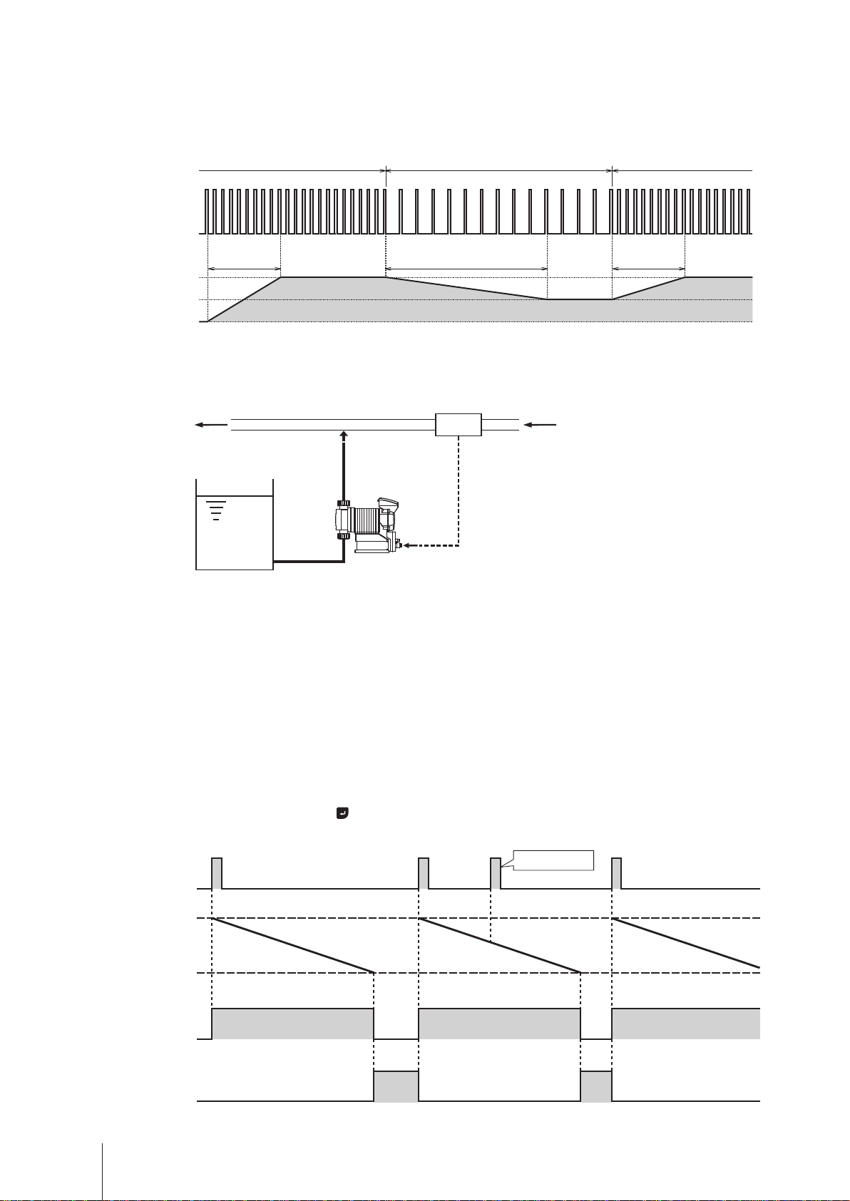
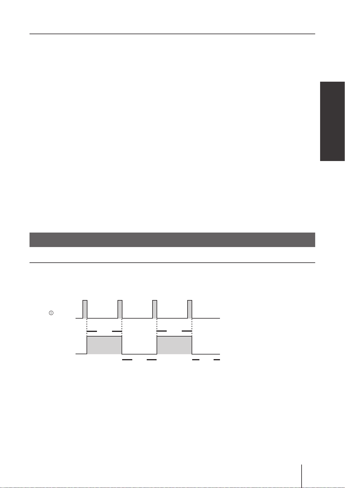
■ Pulse control (see page 42 & 54)
The ow rate is automatically controlled by the ow volume (ml) per pulse and the pulse signal frequency from a
ow meter.
* It takes about 10 pulses for the IX to catch up with the change of the frequency.
10Hz 5Hz 10Hz
Pulse signal
Flow rate at 10Hz
Fow rate at 5Hz
0
Example of use: Chemical dosing in a sewage treatment system
Flow meter
Flow
Supply tank
Pulse signal
Pump
■ Batch control (see page 42 & 54)
The IX discharges a programmed ow volume per pulse and stops when it is completed. The programmed or
remaining ow volume is shown on the controller until it has reduced to zero. In this control mode, the pump
runs at the MAN speed (the pump speed in the manual mode). The pump behaviour can change depending on
the setting of the buffer. See below.
When the buffer is OFF:
Any input of the external pulse signal will be cancelled when the pump is activated for the earlier pulse input.
The next dosing becomes ready after the programmed ow volume has been completed.
*Note the control stops immediately when the key is pushed once.
Cancelled
Pulse input
Programmed
flow volume
Pump
Signal out
(batch comp alarm)
Operational functions
16
Run
Stop
Run
Run
Stop
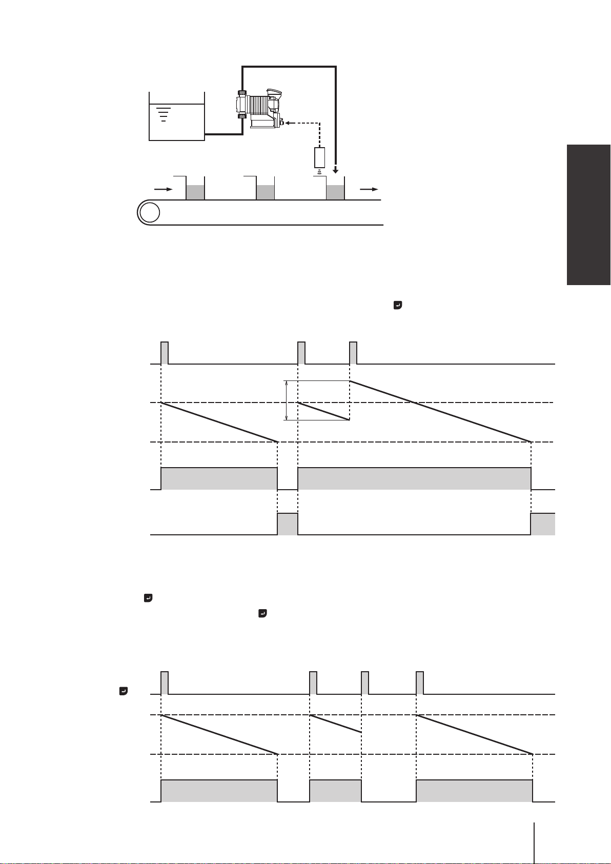
Example of use: Chemical dosing in a production line system
Supply tank
Pump
Pulse
signal
Proximity switch
When the buffer is ON:
Every time the external pulse signal is inputted, the programmed ow volume per pulse is accumulated (max
65535 pulses) even when the pump is activated for the earlier pulse input.
*The control stops immediately and all the pulse accumulation is cleared when the key is pushed once.
Pulse input
Overview
Flow volume for
Programmed
flow volume
Pump
Signal out
(batch comp alarm)
the next signal
Run
Run
Stop Stop
Pulse input by the key:
Instead of the pulse signal input, pushing the key can start or stop the batch control. In this case, the pump
behaves as the control with the buffer OFF even when the buffer is set to ON in the batch control mode.
key
Programmed
flow volume
Pump
Run
Run
Stop Stop
Stop
Operational functions
Run
17
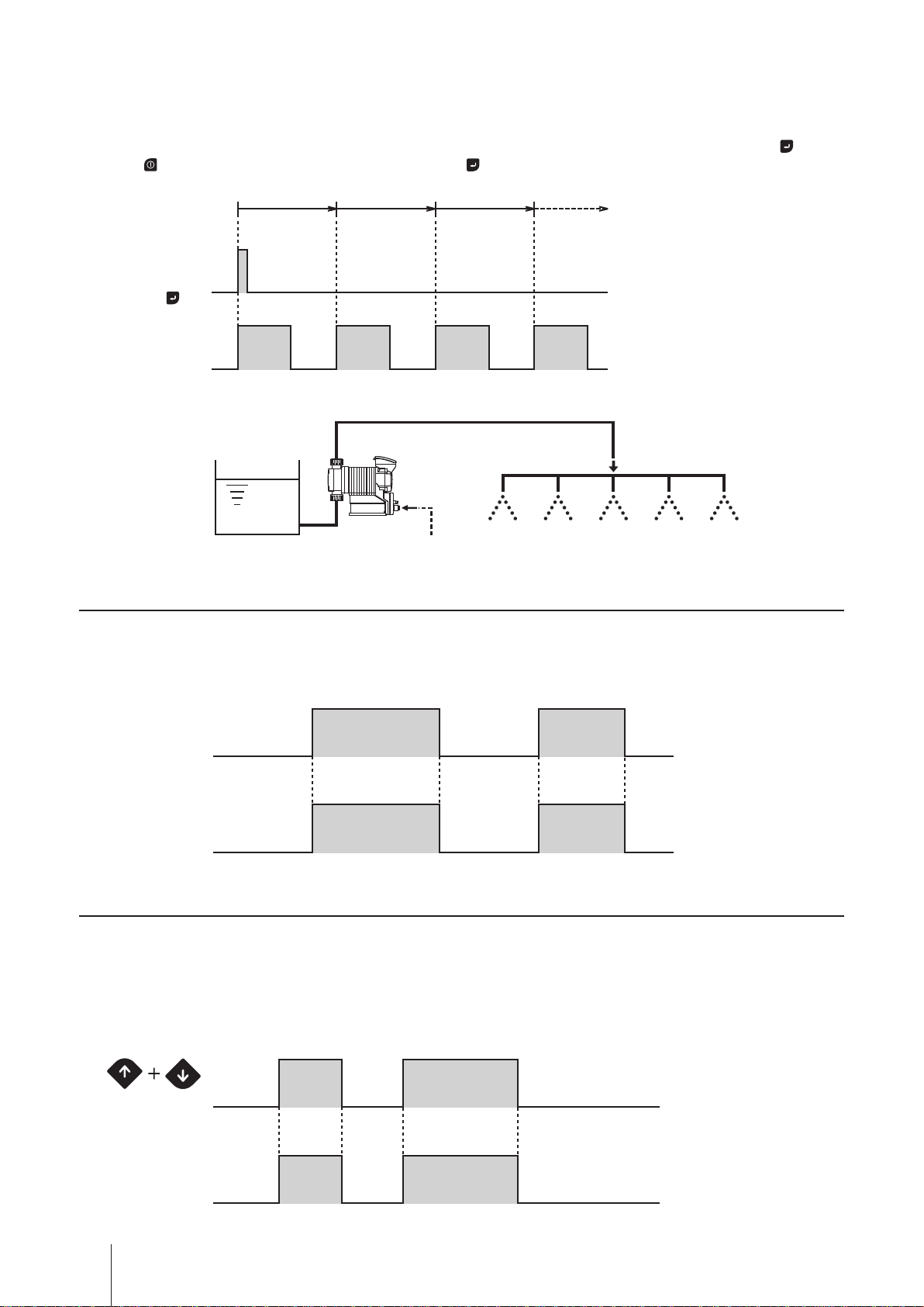
■ Interval batch control (see page 42 & 54)
To make an interval batch control, set a date and time interval and the ow volume. The IX discharges the pro-
grammed ow volume at a set interval. In the diagram below, the interval is set to 1 hour.
* The pump runs at the MAN speed. The control is triggered by either the external pulse signal or the push of the key.
Push the
key to stop the control when it is triggered by the key.
Time
Pulse signal/
Push of
key
Flow
1 hr
2 hr 3 hr
Example of use: Water transfer for a sprinkler system
Pump
Supply tank (water) Pulse signal
AUX function
The pump runs at the AUX speed while receiving the external signal via the AUX terminal. See page 51.
* This function works only when the pump is running in either MAN or EXT mode (see page 40.). The pump returns to the
MAN or EXT mode once the AUX signal stops.
AUX signal
Pump operation
RunStop RunStop
Priming function
The pump runs at the MAN speed (or the maximum stroke rate with default setting) while both the UP and
DOWN keys are pressed. Use this function for priming or degassing. Release both the keys to stop the pump.
See page 55 for detail.
* This function is available at any time except when the pump is in the MAN/EXT selection or menu selection (see page 40.).
Press & hold
Pump operation
RunStop Stop
Press & hold
Run Stop
Operational functions
18
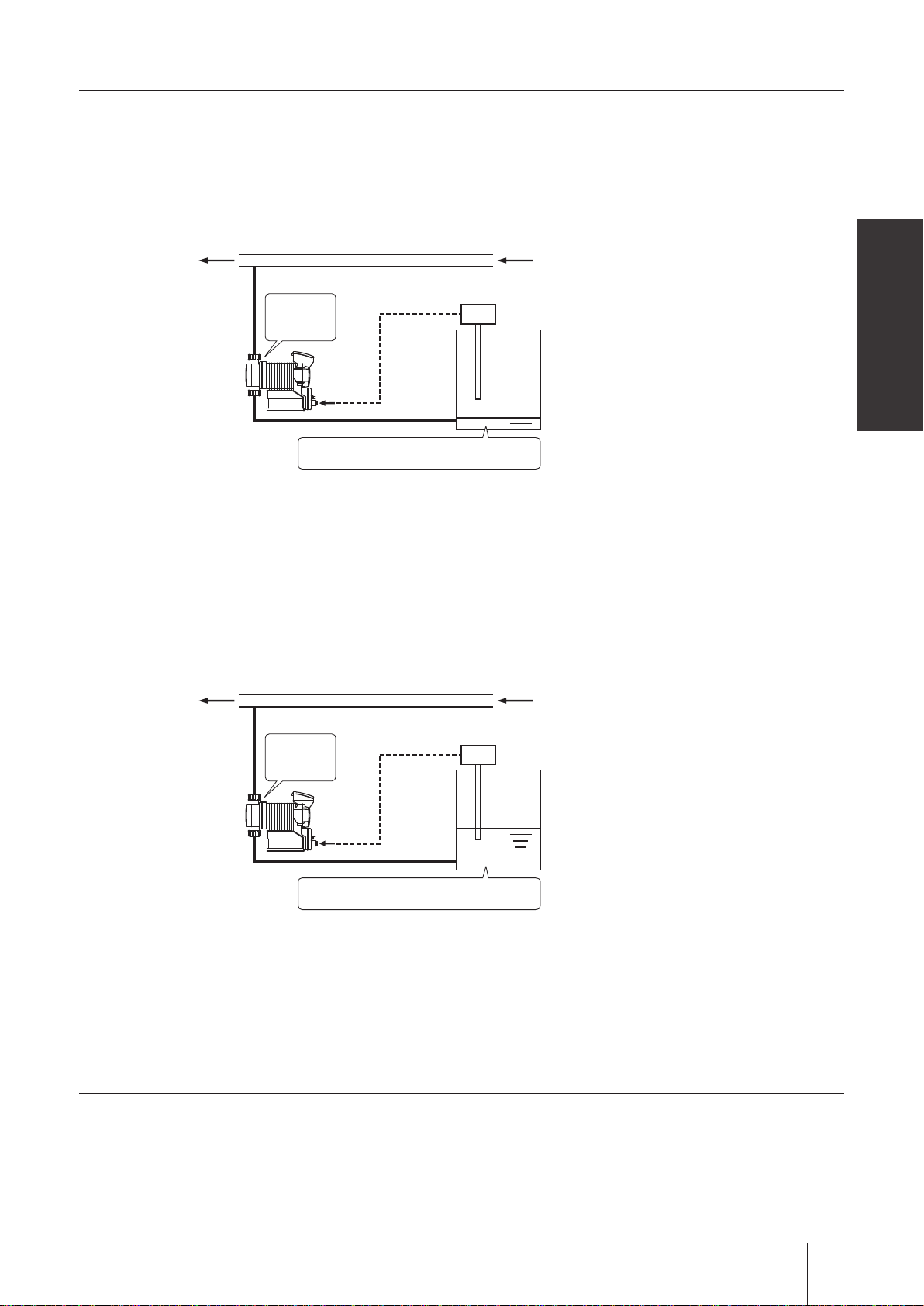
STOP functions
■ STOP function (see page 45)
The start/stop of operation can be controlled by the signal from a level sensor. The operation LED changes
from green to red colour when the pump is receiving the Pre-STOP signal from a level sensor in operation.
See page 32 "STOP IN" for wiring diagram.
Example of use: Liquid level monitoring
Flow
LED lights
in red
Pump OFF
Liquid is below the minimum level
The pump stops when liquid has fallen below the minimum level.
STOP signal
Level sensor
Overview
■ Pre-STOP function (see page 45)
Liquid level in the supply tank can be monitored by the signal from a level sensor. The operation LED changes
from green to orange colour when the pump is receiving the Pre-STOP signal from a level sensor in operation.
See page 32 "STOP IN" for wiring diagram.
Example of use: Liquid level monitoring
Flow
LED lights
in orange
Pump
ON
Liquid is near the minimum level
The operation LED lights in orange colour to inform a user that liquid comes
close to the minimum level in a supply tank.
Pre STOP
Level sensor
signal
Analogue output function
The pump transmits the 0-20mA analogue signal in proportion to the preset ow rates. See page 46.
Operational functions
19
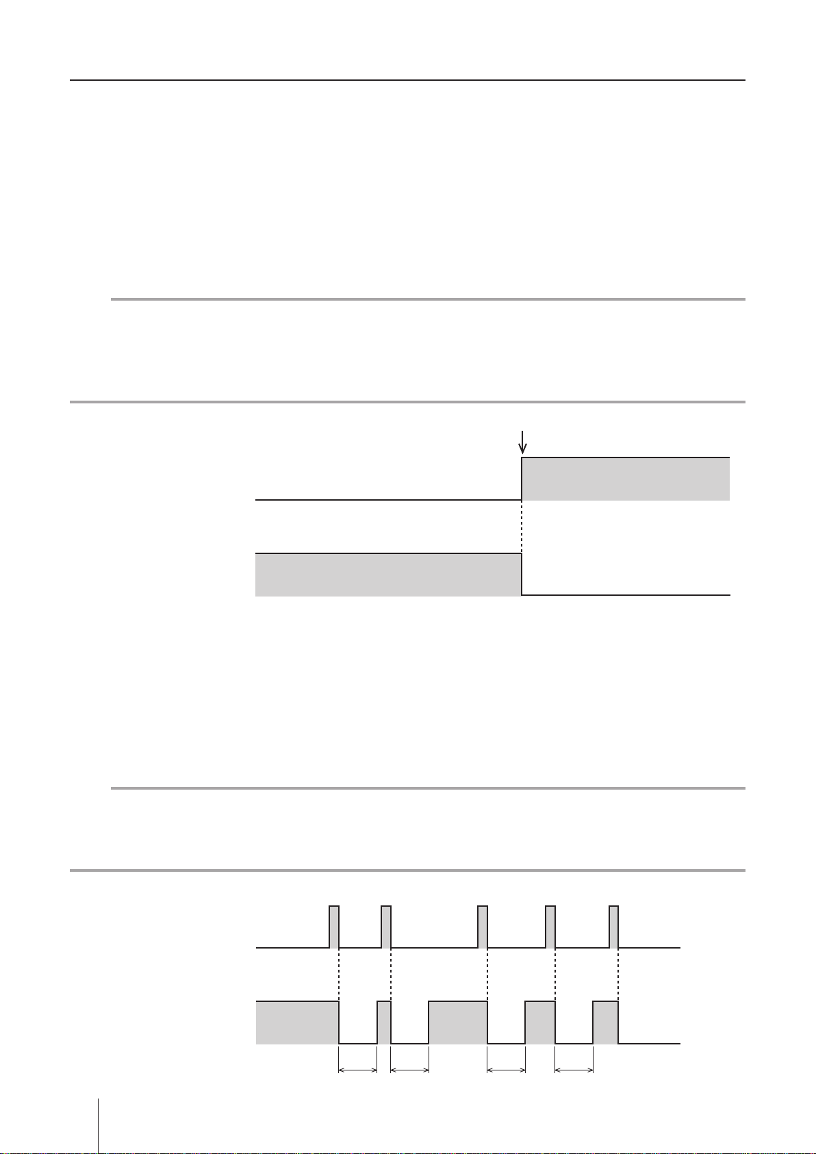
Protective functions
■ Interlock function (see page 32 & 47)
Interlock function works in the same way as the STOP function but uses a preference circuit. Use this function
for emergency stop.
■ Diaphragm rupture detection (see page 45)
The pump stops right after a built-in sensor detects a leak in the compartment at the back of the diaphragm.
In this condition, the operation LED lights in red colour. Replace a broken diaphragm as necessary. See page
63 for diaphragm replacement. To release this error condition, push the start/stop key (or the ESC key under
Probus control.).
NOTE
This capacitance sensor does not work properly if liquid conductivity is 1mS/m or below. Before sending pure
water, oil or any other low-conductivity liquid, check the conductivity to see if it meets the minimum level. If it
is not satised, replace the diaphragm immediately when a leak is found from the drain port. Otherwise, the
pump may fail.
A leak is detected.
ON
Leak detection
OFF
Pump operation
Run Stop
■ Pressure overload/Failed rotation control detection
The pump stops when a built-in pressure sensor detects 1.3-2.0 times higher discharge pressure than the
maximum level or when the hole IC which monitors the motor rotation has failed. In either condition, the operation LED ashes in red colour. The pump resumes operation 30 seconds after the stoppage due to the pres-
sure overload. If the overload has recurred 5 times consecutively, the pump will not resume operation any more
and will keep still. Push the start/stop key to release these error conditions.
NOTE
The activation of this function means the discharge pressure has risen 1.3-2.0 times higher than the maxi-
mum allowable level of the pump. Set up a relief valve to protect the related devices on the discharge line
from the possible pressure rise as necessary.
ON
Overload detection
1 2 3 4 5times
Pump operation
20
Operational functions
OFF
Run Stop
30sec 30sec 30sec 30sec

■ Alarm output function (see page 47)
Enable or disable the output of the batch completion, STOP, Pre-STOP, interlock, diaphragm rupture detection,
pressure overload detection, and/or drive error detection functions which is preset to the Alarm OUT 1 and 2,
or the output of the volume proportional pulse preset only to the Alarm OUT 2. See page 33 "Alarm OUT (DIN
connector)" for wiring diagram.
Alarm OUT 1 (OUT 1) : Mechanical relay output (no voltage contact 1a×1 250VAC 3A, resistive load)
Alarm OUT 2 (OUT 2) : PhotoMOS relay output (no voltage contact 1a×1 24VAC/DC 0.1A, resistive load)
Other functions
■ Suction speed setting (see page 51)
Suction speed is adjustable by 4 levels depending on liquid property. Reduce suction speed so as to reduce
inertia resistance for the delivery of viscous liquid or to prevent cavitation for gaseous liquid. Select 100% (de-
fault), 75%, 50% or 25%.
■ Maximum ow rate setting (see page 51)
The maximum allowable ow rate of the IX can be reduced if necessary. The default setting of the IX-C150 is
150L/H and the IX-C060 is 60L/H.
Overview
■ Diaphragm position adjustment (see page 51)
A pump shaft expands or contracts for easy diaphragm replacement. Select "MAX OUT Pos." through the
"Other Features" menu in order to extend the pump shaft to the maximum. Select "MAX IN Pos." to contract it
to the minimum and mount the pump head. See page 63 "Diaphragm replacement" for detail.
■ Anti chattering programming (see page 51)
Program a pulse recognition time for the IX not to be adversely affected by chattering or noise. Factory default
setting is 5 msec. This means the pump recognizes the pulse length of 5 msec or more. The other options are
1 and 2 msec and should be selected for the shorter pulse length, however, note the shorter the recognition
time is, the more susceptible to the interference of noise the pump becomes. Note the maximum allowable
input frequency of the IX is 100Hz.
■ Output logic setting (see page 51)
Select "normally open" or "normally closed" for the Alarm OUT 1 (OUT 1) and 2 (OUT 2) outputs.
■ Flow unit setting (see page 51)
Select L/H or GPH for the ow rate indication.
■ Language setting (see page 51)
Select your language through the language selection.
■ Keypad lock (see page 56)
The IX-C is shipped with the access codes at default values (00000). In order to prevent against unauthorized
tampering, you will need to change the access codes to your own values.
■ Default setting
Power on the pump while pressing the ESC key to recall default setting. Note the ow volume per shot ob-
tained through the calibration process (see page 37) remains the same.
Operational functions
21
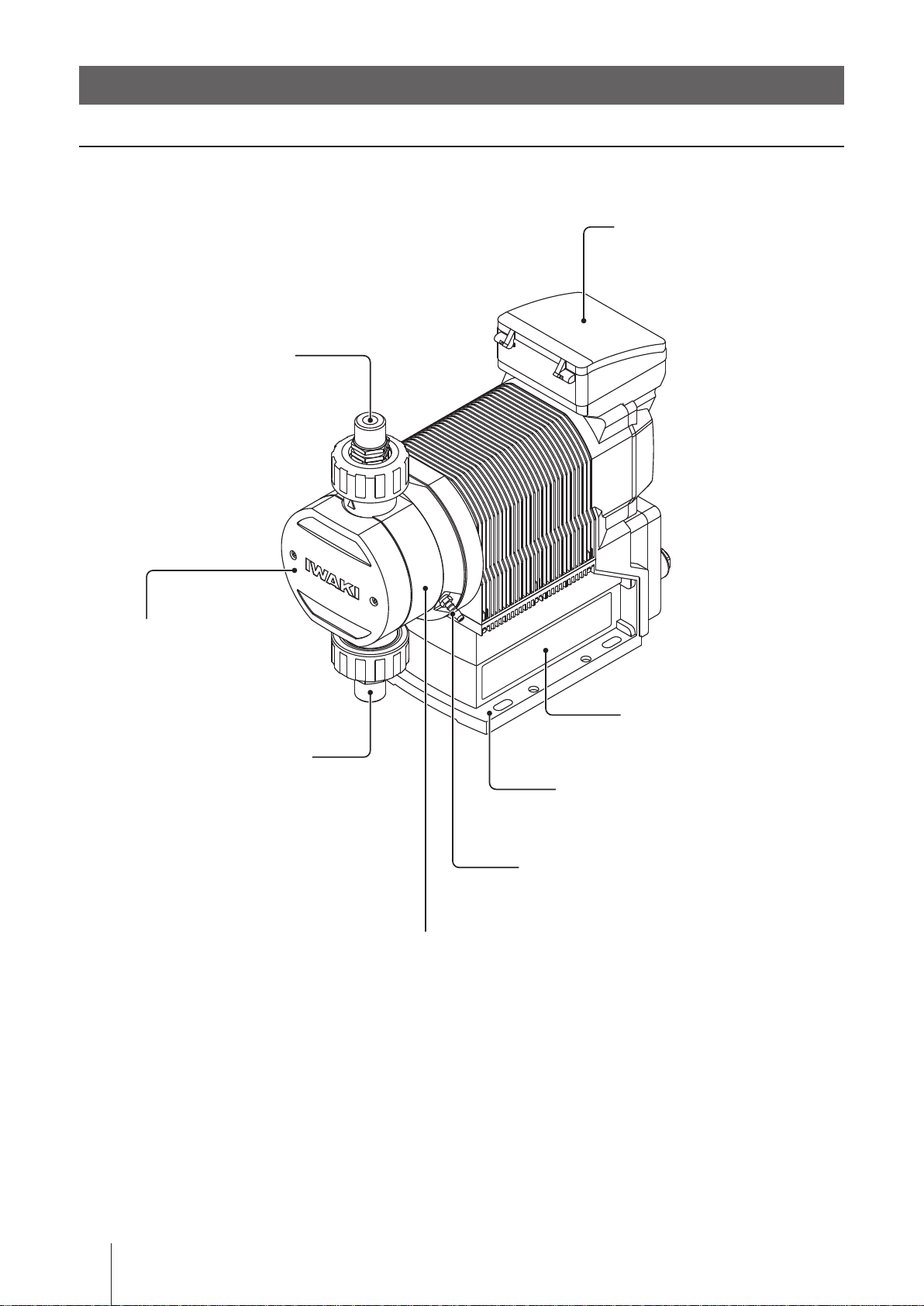
Part names
Pump
Control unit
Used for the start/stop of the pump
and operation control/program-
ming. See next page for detail.
Unhook the cover to open it. Push
down until it clicks once to close it.
Outlet
Bolt cover
Take out the cover to
remove the pump head.
Inlet
Pump head
Nameplate
Describes the pump specifi-
cations.
Base
Always anchor it with bolts.
Drain port (Vent hole)
Chemical liquid will be released from here.
* Do not plumb this drain port to a supply tank
with sodium hypochlorite or any other strong
acid. Make sure this port "breathes" in a clean
atmosphere.
22
Part names
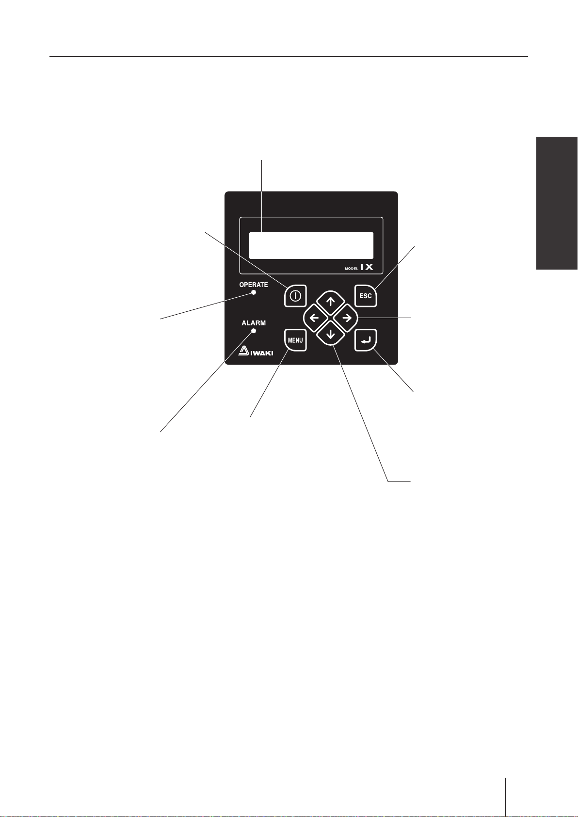
Operation panel
Start/Stop key
Used for starting/stopping the pump
operation or moving back to the MAN/
EXT selection.
Display
An operational status, a selected mode
and programmed values are shown here.
Overview
ESC key
Used for cancelling pro-
gramming and moving back
to a previous menu.
Operation LED
Lights in green in operation
and in red during stoppage,
programming, error conditions.
Lights in orange as Pre-STOP
signal is entered. See page 24.
ALARM LED
Lights to notice the damaged diaphragm, the inter-
lock activation or so.
MENU key
Used in the MAN/EXT
selection screen for calling
up the menu screen.
Left/Right key
Used for moving through
items. Press and hold both
keys for 3 seconds to dis-
able keypads.
Enter key
Used for making a deci-
sion in the menu screen or
MAN/EXT selection.
UP/DOWN key
Used for changing numeric
values or selecting a programming mode.
The pump enter the priming
mode while both the keys
are pressed.
Part names
23
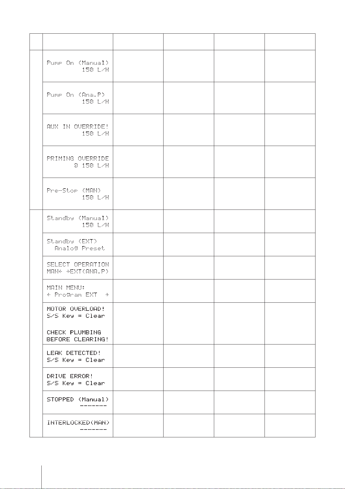
■ Basic displays & Pump states
Display
Operation LED
lights in red
Operation LED
lights in green
Operation LED
lights in orange
ALARM LED
lights in red
Operation
―
―
― AUX operation ― ―
―
― ―
A wait state in
manual mode
Operation in
manual mode
Operation in EXT
mode (Analogue
control)
Operation in prim-
ing mode
― ― ―
― ―
― ―
― ―
Pre-STOP func-
tion is active.
Pre-STOP func-
tion is active.*
A wait state in
EXT mode (ana-
logue control)
MAN/EXT selec-
tion
Menu screen ― ― ―
Pressure overload
Stop
or
protection is ac-
tive.
Diaphragm is bro-
ken.
Failed rotation
control is detected.
Operation stop in
manual mode
― ― ―
― ― ―
Pressure overload
― ―
― ―
― ―
― ―
protection is ac-
tive.*
Diaphragm is bro-
ken (Alarm OUT 1
default setting).*
Failed rotation
control is detect-
ed.*
Operation stop in
manual mode*
― ― ―
* The Alarm LED becomes active when a function is allocated to the Alarm OUT 1 or 2.
Part names
24
Interlock function ac-
tivation (Alarm OUT
2 default setting)*
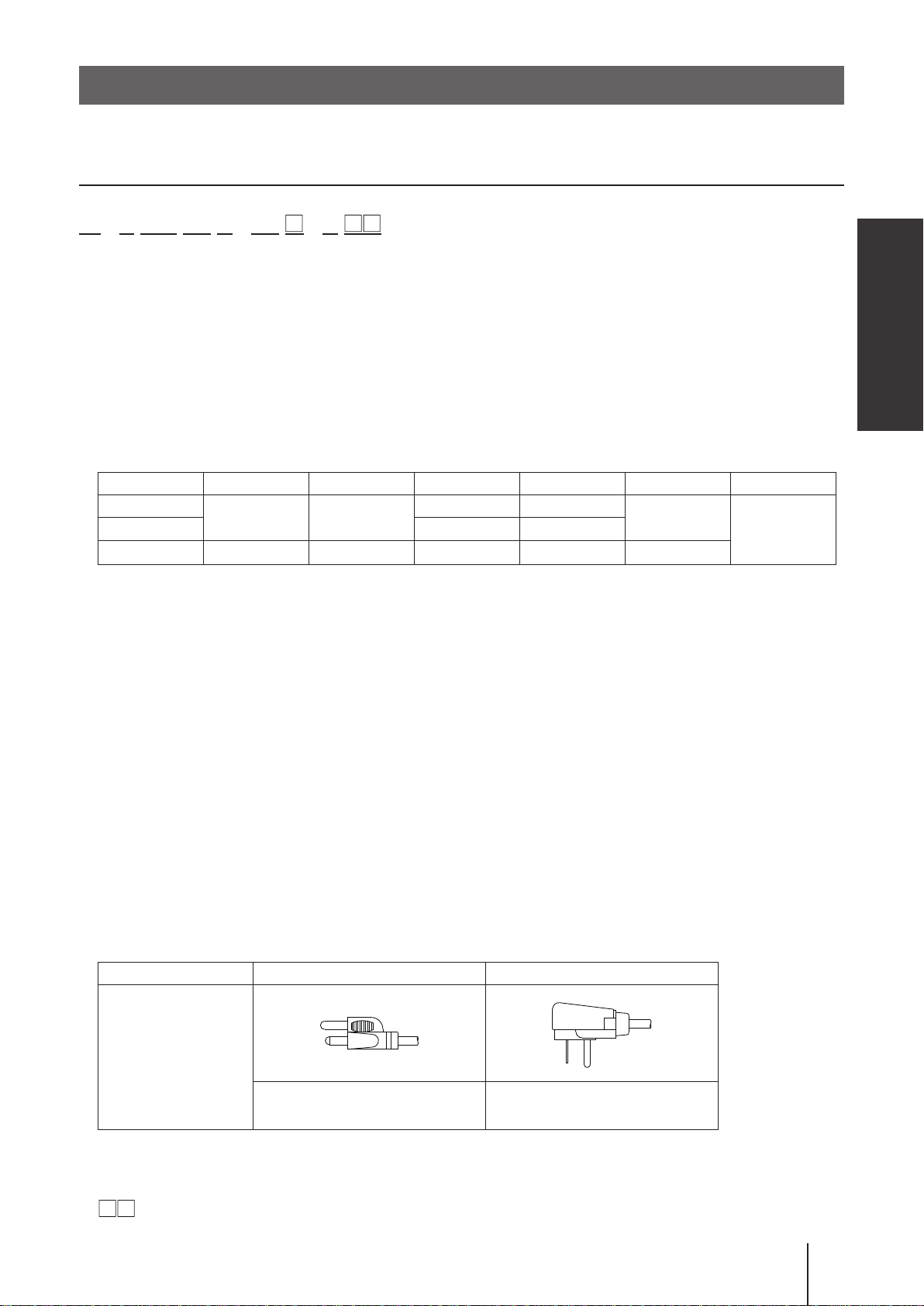
Identication codes
Each code represents the following information.
Pump
IX - C 150 TC N - TB - U
a b c d e f g h i
a. Series name
b. Drive unit
c. Pump unit (Max ow)
150 : 150 [L/H]
060 : 60 [L/H]
d. Wet end materials
Code Pump head Ball valve Valve seat O ring Valve gasket Diaphragm
TC
TE EPDM EPDM
S6 SUS316 SUS316 SUS316
*EPDM is not a wet end.
PVDF CE
FKM FKM
―
―
PTFE
Overview
PTFE+EPDM*
Material code
PVDF : Polyvinylidene diuoride PTFE : Polytetrauoroethylene
EPDM : Ethylene-propylene rubber FKM : Fluorine-contained rubber
CE : Ceramics SUS316 : Austenite stainless
e. Connection
N : NPT thread
FA : ANSI ange
f. Controller housing
TF : Top Front TB : Top Back TR : Top Right TL : Top Left RF : Right Face LF : Left Face
g. Control code
1 : IX-C060
2 : IX-C150
h. Power plug
Code U U2
Plug shape
115V (1950mm length) 230V (1950mm length)
i. Special version
No code : Standard models
: Customized models will be coded.
Identication codes
25
Installation
This section describes the installation of the pump, piping and wiring.
Read through this section before work.
Points to be observed
Observe the following points when installing the pump.
• Risk of electrical shock. Be sure to turn off power to stop the pump and related devices
before service is performed.
If you notice any abnormal or dangerous conditions, suspend operation immediately and
•
inspect/solve problems.
• Do not place explosive or ammable material near the pump.
• Use of a damaged pump could lead to an electric shock or death.
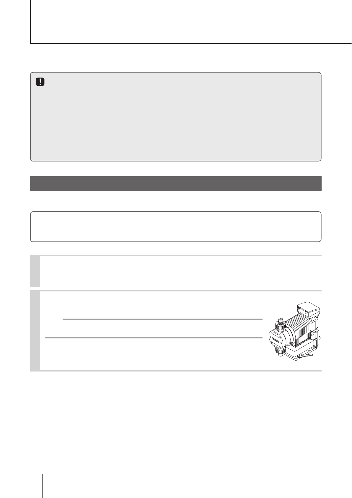
Pump mounting
Select an installation location and mount the pump.
Necessary tools
• Four M8 bolts (pump mounting) • Adjustable wrench or spanner
Select a suitable place.
1
Always select a at oor free of vibrations. See page 10 for detail.
Anchor the pump by four M8 bolts.
2
Be sure to x the pump at four points.
NOTE
Select a level location, or the ow may reduce.
Pump mounting
26
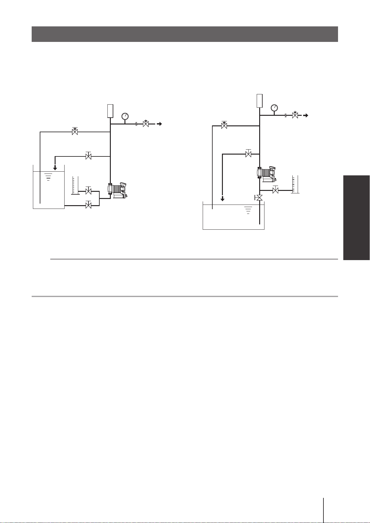
Pipework
■ Piping layout
Flooded suction application Suction lift application
Accumulator/Chamber
Accumulator/Chamber
Pressure gauge
Relief valve
Back pressure valve
Air vent/drain valve
Calibration
cylinder
Pump
Tank
Relief valve
Air vent/
drain valve
Pump
Pressure gauge
Back pressure valve
Installation
Calibration
cylinder
Tank
NOTE
• The suction line I.D. should be equal to or wider than the I.D. of the pump.
• When handling liquids that generate gas bubbles (sodium hypochlorite or hydrazine solution), install the pump
in a cool and dark place. Flooded suction installation is strongly recommended.
Pipework
27
 Loading...