

IWAKI FW-H Series, FW-20HT1, FW-40HT2, FW-20HT2, FW-40HT1 Instruction Manual

Read this manual before use of product
IWAKI
Pne um atic D rive Bel lows Pump
FW-H
Instruction Manual

Thank you for selecting an Iwaki Pneumatic Drive Bellows Pump the FW-H. This instruction manual deals with “Safety instructions”, “Outline”, “Installation”, “Operation” and
“Maintenance” sections. Please read through this manual carefully to ensure the optimum performance, safety and service of your pump.
Contents
Important instructions ···································································· 1
Safety instructions ·········································································· 2
Outline 1. Unpacking & Inspection
..................................................
6
2. Operating principle
..........................................................
6
3. Model codes
.....................................................................
7
4. Specifications
...................................................................
7
5. Outer dimensions
.............................................................
8
6. Part names
........................................................................
9
7. Overview
........................................................................
13
Installation 1. Before installation
..........................................................
15
2 Installation/Piping/Wiring
..............................................
17
Operation 1. Before operation
.............................................................
30
2. Operation
........................................................................
30
3. Check items
....................................................................
31
Maintenance 1. Troubleshooting
..............................................................
33
2. Maintenance & Inspection
.............................................
35
3. Wear parts
......................................................................
36
This instruction manual should be kept on hand by the end user for
quick reference.
Contact us or your nearest dealer if you have any questions.
- 1 -
Impor tant instruc tions
For exportation
Technology related to the use of goods in this instruction manual falls in the category of
technology contained in the Foreign Exchange Order Attachment, which includes complementary export control of technology. Please be reminded that export license, which
is issued by the Ministry of Economy, Trade, and Industry could be required, when this is
exported or provided to someone even in Japan.
Nonobservance or misapplication of “Caution” sections could lead to a personal injury or property
damage.
For the Safe and
Correct Handling of the Pump
●
"Safety Instruction" section deals with important details about handling of the product. Before
use, read this section carefully for the prevention of personal injury or property damage.
●
Observe the instructions accompanied with "WARNING" or "CAUTION" in this manual. These
instructions are very important for protecting users from dangerous situations.
●
The symbols on this instruction manual have the following meanings:
WARNING
Nonobservance or misapplication of “Warning” sections could lead to a serious accident which may
result in death.
CAUTION
Types of Symbols
Indicates that “Warning” or “Caution” must be exercised. Inside this triangle, a concrete and practical image provided as a warning or caution message is depicted.
Indicates a prohibited action or procedure. Inside or near this circle, a concrete and
practical image of the activity to be avoided is depicted.
Indicates an important action or procedure which must be performed or carried out
without fail. Failure to follow the instructions herein can lead to malfunction or
damage to the pump.
WARNING
- 2 -
●
When turning on power
Make sure there is no one around the pump when connecting the power
cable. Any power supply switch is not provided on the pump. Connecting the
power cable, a solenoid valve starts to supply air to run the pump.
●
Do not remodel the pump
Never remodel the pump. We are not responsible for any injury or damage
due to modification.
●
Specified application only
Use of the pump in any application other than those clearly specied may
result in a personal injury or property damage.
●
Drainage
Do not drain chemicals directly onto the ground or a waste channel.
Disposal of chemicals should be in accordance with an applicable law.
●
Do not come in contact with the pump
Risk of burn. The surface temperature of the pump and piping may rise high.
Always wear protective gloves when liquid temperature is more than 50°C.
●
Observe the specified voltage
Risk of a fire or electrical shock. Do not supply any power voltage other than
specified one.
●
Before maintenance
Rinse the pump with pure water. Be sure to wear protective gear (protective
goggles, cap, mask and acid-resistant gloves).
●
Qualified operator only
The pump must be handled by a qualified operator(s) who has trained in the
safe operation of the pump.
●
Use a strong chain or rope to lift the pump up
Otherwise the pump may accidentally fall down, resulting in serious injury or
death.
●
Before use
Rinse the pump with pure water or a liquid to be sent.
●
Countermeasure against efflux
Take a protective measurement against accidental chemical efflux and
splash at pump or piping breakage. Also, take an appropriate measurement
to prevent accidental outflow from directly soaking into the ground.
Safety inst ruc tions
CAUTION
- 3 -
Safety inst ruc tions
●
Power OFF
Be sure to turn off the power before a maintenance/repair work. Make
sure no one turns on the power while working on the pump, otherwise a
serious accident may result. If your work field is noisy or dark, let other
people know about the situation by displaying a notice such as "POWER
OFF(Maintenance)" near the power switch.
●
Storage limit
Risk of fire and/or health damage. Do not instal or store the pump in explosive atmosphere, heavy dust or corrosive gas (such as chlorine gas).
●
Ventilation
Keep good ventilation when handling a toxic/odorous liquid. Always wear
protective gear (protective mask, goggles and gloves, etc.).
●
Pump disposal
Dispose of an used o r da m a ged p u mp i n a ccorda n ce with local l a w s an d r egulations. Con s u l t a l icen se d in d u s trial waste produ cts d is po si n g compa ny.
●
Returning the pump
Drain a chemical and rinse the wet ends for safe transportation before
returns.
●
Observe the maximum stroke rate
Operation above the maximum stroke rate (FW-20HT: 120spm, FW-40HT:
80spm) may reduce the life of bellows. Set the controller not to run over the
maximum stroke rate even under dry running.
●
Do not run the pump with the following liquid
• Liquid easily crystallizes
• Slurry
• Solvent naphtha
●
Liquids to be handled with care
• Stripper
• Solvent (explosion proof is required.)
• Hydrazine
• Fuming sulfuric acid
●
Static electricity
When low electric conductivity liquids such as ultra-pure water and fluor
inactive liquid (e.g. Fluorinert
TM
) are handled, the static electricity may be
generated in the pump and may cause static discharge. Take countermeasures to remove the static electricity.
CAUTION

- 4 -
●
Supply air pressure
Observe the supply air pressure range below. Otherwise the bellows may
deform.
Pump model Liquid temperatrue range Supply air pressure range
FW-20HT1
FW-20HT2
10-100°C 0.196-0.490MPa
101-150°C 0.147-0.294MPa
151-180°C 0.147-0.196MPa
FW-40HT1
FW-40HT2
10-100°C 0.196-0.490MPa
101-150°C 0.147-0.294MPa
151-180°C 0.147-0.196MPa
Always stop the pump before setting a supply air pressure.
●
Liquid temperature
Observe the allowable liquid temperature range.
FW-20HT & -40HT: 10 - 180°C
A sharp liquid temperature change (heat shock) may significantly reduce the
life of the pump. Contact us for detail.
●
When stopping the pump
• Before stopping the pump, release discharge pressure. Otherwise, the bel-
lows may deform due to residual pressure.
• Do not close a discharge valve as stopping the pump. An impact pressure
may deform the bellows or a connecting plate.
●
After stopping the pump
• Do not supply air to both the right and left air-supply ports at once to pre-
vent the bellows deformation.
• Do not leave the pump with any chemical in the bellows for a long period.
Some chemical can penetrate the bellows and corrode metal parts. Run
the pump for ten minutes every day for replacing air.
●
Air exhaust port
Do not narrow an air exhaust line (for example by reducing the tube bore).
The residual pressure in the pump may deform the bellows.
●
During pump operation
Make sure all suction and discharge valves are open in order to fill the lines
with liquid.
●
Electrodes
The electrode occasionally fails to detect leakage depending on operating
condition. Contact us for detail.
Safety inst ruc tions
CAUTION

- 5 -
- 5 -
Outline
1. Unpacking & Inspection ........................6
2. Operating principle................................6
3. Model codes .........................................7
4. Specifications .......................................7
5. Outer dimensions ..................................8
6. Part names ...........................................9
7. Overview .............................................13

- 6 -
- 6 -
OUT
IN
Bellows Air chamber
Compression
Air supply
Pump head
Expansion
Air exhaust
OUT
IN
Compression
Air supply
Expansion
Air exhaust
: Liquid flow
: Air flow
Expansion/compression: Bellows reciprocating motion
1. Unpacking & Inspection
Outline
On unpacking the product, check the following
points. If you find any problems, contact your
nearest dealer.
1. Check the information on nameplate to see if the
product is delivered as per order.
2. Check for transit damage, deformation and
loose bolts.
3. If all accessories are delivered as per order.
a. Controller
(The AC-1, FD-2, SC and FDC-1)
b. Quick exhaust valves
An Iwaki pneumatic drive bellows pump has
fluoric wet ends and is designed for semiconductor manufacturing processes.
The pump unit has two air chambers and a pair
of bellows. The reciprocating motion of the
bellows in the air chambers makes suction and
discharge actions.
a. Liquid is sucked via the inlet as the bellows
expands.
b. Liquid is discharged via the outlet as the bellows
contracts.
2. Operating principle
Wiring work is different at each controller type.

- 7 -
- 7 -
3. Model codes
FW - 20 H T 1 - 01
a b c d e f
a. Series code
b. Maximum flow rate
20 : 20 L/min
40 : 40 L/min
c. Temperature range
T : 10-180°C
d. Pump connection (Inlet/Outlet)
T : Tube (standard)
e. Pump head-Bellows connection
1 : Mechanical
2 : Welded
f. Special specifications
No symbol : Standard
01 : Special specifications (01, 02
······
)
4. Specifications
Item FW-20HT1 & -20HT2 FW-40HT1 & -40HT2
General
Max. flow rate*1 20 L/min 40 L/min
Max. stroke rate 120 spm 80 spm
Suction lift*2 1 m
Liquid temperature range 10-100°C 101-150°C 151-180°C 10-100°C 101-150°C 151-180°C
Supply air pressure (MPa) 0.196-0.490 0.147-0.294 0.147-0.196 0.196-0.490 0.147-0.294 0.147-0.196
Wet ends PFA, PTFE
Pump connection
PFA tube
(O.D. 19 × I.D. 16 mm)
PFA tube
(O.D. 25 × I.D. 22 mm)
Supply air connection Rc 1/4" Rc 3/8"
Max. air consumption
(at max. flow rate and max.
supply air pressure)
330
Nl/min
200
Nl/min
140
Nl/min
480
Nl/min
300
Nl/min
220
Nl/min
Ambient temperature range 0-40°C
Driving method Pneumatic drive
Proximity
switch
Model High-frequency proximity switch
Output NPN DC open/close output
Power voltage 10-30VDC
*1.
The maximum flow rate is based on pumping ambient clean water.
*2
. The suction lift is based on pumping ambient clean water at the maximum spm.
Outline
- 8 -
- 8 -
Outline
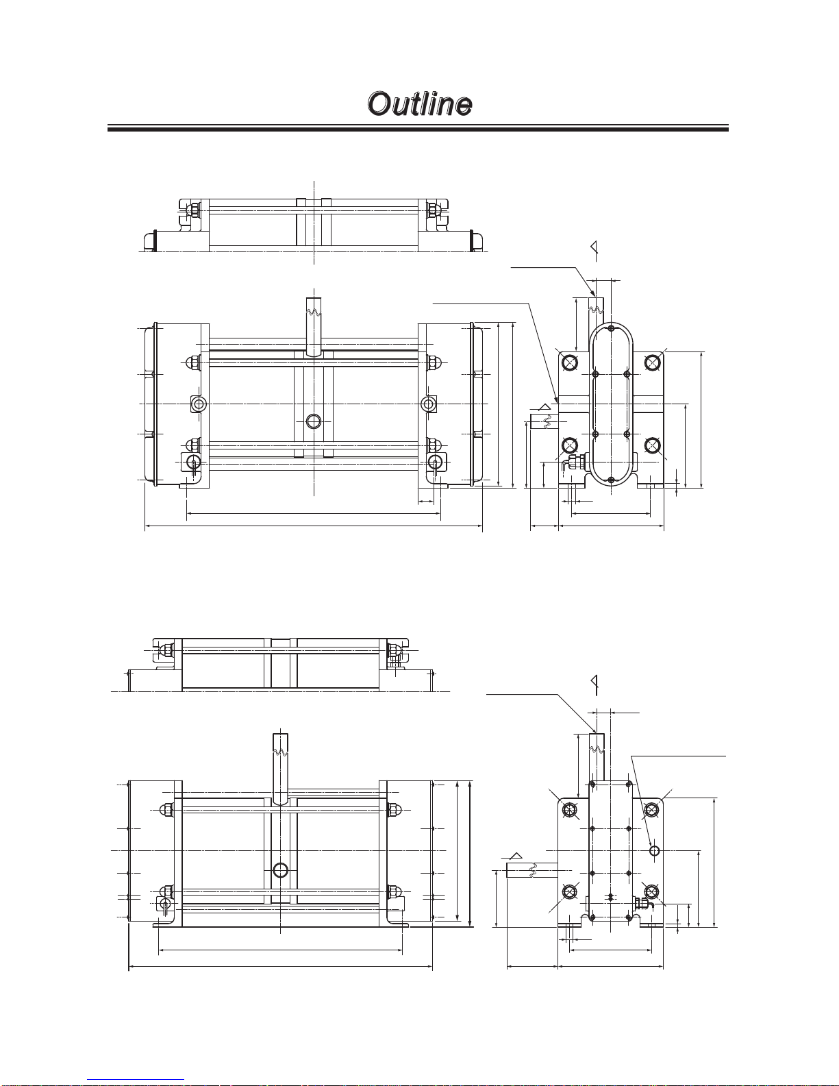
5. Outer dimensions
346
458
218
221
90
35
IN
(100)
140
105
10
112
182
6
22
(100)
OUT
AIR SUP. 2-Rc1/4
21
2- ø19 × ø16
IN
OUT
12
140
180
434
542
240
250
(100)
102
25.5
(100)
6
40
130
220
AIR SUP. 2-Rc3/8
2- ø25 × ø22
FW-20HT Unit: mm
FW-40HT Unit: mm
Weight: 14kg
Weight: 24kg
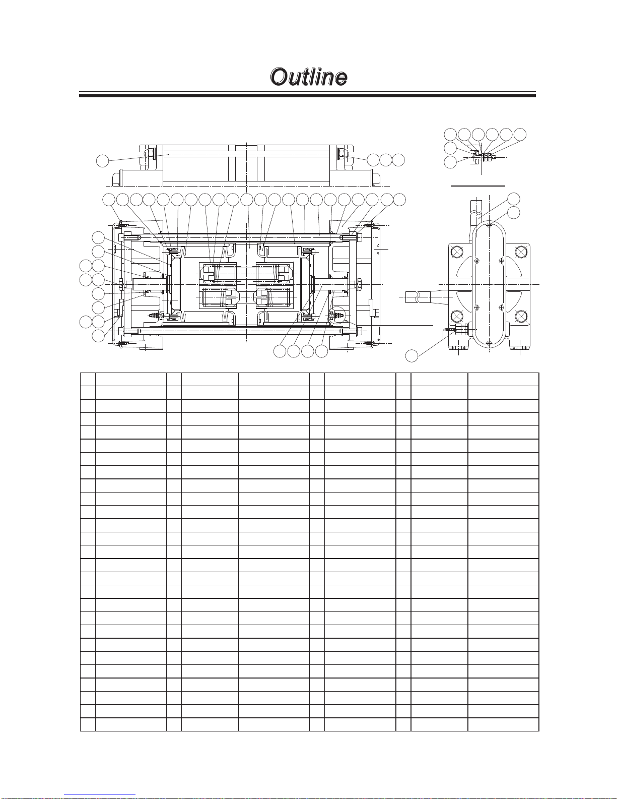
SECTION:N
1 46 6 22 16 15 24 3132 23 144510711124732 17 18
21 13 30 29
8
9
26
19
25
28
51
33
27
20
52
35 36 37
34
40 42 43 38 44 45
41
39
48
50
49
N: LEAK SENSOR
- 9 -
FW-20HT1
Outline
6. Part names
No. Part names
Q'ty
Materials Remarks
Q'ty
Part names
Q'ty
Materials Remarks
1 Pump head 1 PTFE 27 S crew 8 Stainless steel M4×8
2 Valve 4 PTFE 28 Packing 2 FKM
3 Valve spring 4 PTFE 29 Bearing 2 Filled PTFE
4 Valve case 4 PTFE 30 Stop ring 2 Stainless steel Nominal 32
5 Bellows 2 PTFE 31 Guide bush 4 POM
6 Bellows ring 2 SUS304 4F coating 32 Cylinder head cover 2 PPE
7 Bellows plate 2 SUS304 33 Proximity detector 2
8 O ring 2 FKM G-60 34 Stud bolt 4 SUS30 4 4F coating
9 O ring 2 FKM S-25 35 Domed cap nut 8 Stainless steel M10 4F coating
10 Bellows flange 4 SUS304 36 Plate washer 8 Stainless steel M10 4F coating
11
Hex. soch cap bolt
12 Stainless steel M5×16 37
Conical spring washer
24 Stainless steel
Nominal 10 4F coating
12 Spring washer 12 Stainless steel M5 38 Plate washer 4 Stainless steel M4
13 Pump shaft 2 SUS304 Hard chrome plating 39 Leak sensor 4 SUS304
14 Connecting plate 2 SUS304 40 Gasket 4 PTFE
15 Connecting shaft 2 SUS304 41 O ring 4 FKM S-4
16 Shaft cover 2 SUS304 4F coating 42 O ring 4 FKM S-12
17
Hex. soch cap bolt
4 Stainless steel M8×25 43 Gasket C 4 PTFE
18 Spring washer 4 Stainless steel M8 44 Spring washer 8 Stainless steel M4
19 Hex. nut 2 Stainless steel M12 45 Hex. nut 8 Stainless steel M4
20 Spring washer 2 Stainless steel M12 46 O ring 2 FKM AS568-249
21 Stop ring 2 Stainless steel E-15 47 O ring 4 FKM P-16
22 Cylinder 2 A6 063 4F coating 48 Tube 2 PFA
23 Cylinder head 2 ADC12 4F coating 49 Cord gland 2 PP S CL- 6A
24 Gasket 4 FKM 50 Screw 12 Stainless steel M4×8 4F coating
25 Shaft packing 2 FKM 51 Installed base 2 PP
26 Packing stopper 2 SUS304 52 Screw 4 Stainless steel M3×10

SECTION:N
1 22 16 15 24 31 14 23324510711124732 17 18
21 13 30 29
8
9
26
19
25
28
51
33
27
20
52
35 36 37
34
40 42 43 38 44 45
41
39
48
50
49
N: LEAK SENSOR
- 10 -
FW-20HT2
Outline
No. Part names
Q'ty
Materials Remarks
Q'ty
Part names
Q'ty
Materials Remarks
1 Pump head 1 PTFE 27 S crew 8 Stainless steel M4×8
2 Valve 4 PTFE 28 Packing 2 FKM
3 Valve spring 4 PTFE 29 Be ar ing 2 Filled PTFE
4 Valve case 4 PTFE 30 Stop ring 2 Stainless steel Nominal 32
5 Bellows 2 PTFE 31 Guide bush 4 POM
7 Bellows plate 2 SUS304 32 Cylinder head cover 2 PPE
8 O ring 2 FKM G-60 33 Proximity detector 2
-
9 O ring 2 FKM S-25 34 Stud bolt 4 SUS30 4 4F coating
10 Bellows flange 4 SUS304 35 Domed cap nut 8 Stainless steel M10 4F coating
11
Hex. soch cap bolt
12 Stainless steel M5×16 36 Plate washer 8 Stainless steel M10 4F coating
12 Spring washer 12 Stainless steel M5 37 Spring washer 8 Stainless steel M10 4F coating
13 Pump shaft 2 SUS304 Hard chrome plating 38 Plate washer 4 Stainless steel M4
14 Connecting plate 2 SUS304 39 Leak sensor 4 SUS304
15 Connecting shaft 2 SUS304 40 Gasket 4 PTFE
16 Shaft cover 2 SUS304 4F coating 41 O ring 4 FKM S-4
17
Hex. soch cap bolt
4 Stainless steel M8×25 42 O ring 4 FKM S-12
18 Spring washer 4 Stainless steel M8 43 Gasket C 4 PTFE
19 Hex. nut 2 Stainless steel M12 44 Spring washer 8 Stainless steel M4
20 Spring washer 2 Stainless steel M12 45 Hex. nut 8 Stainless steel M4
21 Stop ring 2 Stainless steel E-15 47 O ring 4 FKM P-16
22 Cylinder 2 A6 063 4F coating 48 Tube 2 PFA
23 Cylinder head 2 ADC12 4F coating 49 Cord gland 2 PP S CL- 6A
24 Gasket 4 FKM 50 Screw 12 Stainless steel M4×8 4F coating
25 Shaft packing 2 FKM 51 Installed base 2 PP
26 Packing stopper 2 SUS304 52 Screw 4 Stainless steel M3×10
 Loading...