

Iwaki FS-100NF User Manual
Read this manual before use of product
IWAKI
Pneumatic Drive Bellows Pump
FS-100NF
Instruction Manual

Thank you for selecting IWAKI's Pneumatic Drive Bellows Pump the FS-100NF series.
This instruction manual deals with “Safety Section” “Product outline” “Installation
Section” “Operation Section” and “Maintenance Section”.
Please read through this manual carefully to ensure the optimum performance, safety and
service of the FS-100NF series.
Contents
Before use of the FS-100NF series pumps
IMPORTANT INSTRUCTIONS
Safety Section (Instructions to prevent accidents)
..................................................................
.................................
1
2
PRODUCT OUTLINE
1. Unpacking and Inspection
2. Operation Principle
3. Identification Codes
4. Specifications
5. Outer Dimensions/Mass
6. Names of Parts and Structure of Pump
7. Description on Body and Label
INSTALLATION SECTION
1. Before Use
2. Installation, Piping, and Wiring
OPERATION SECTION
1. Preparation
2. Pump Operation
3. Points to Be Observed in Operation
MAINTENANCE SECTION
1. Causes of Trouble and
Troubleshooting
2. Maintenance and Inspection
3. Consumable Parts
..............................................................................
....................................
...............................................
..............................................
.......................................................
.......................................
..........................
......................................................................
.........................................................
...........................
.........................................................................
.........................................................
.................................................
...................
.....................................................................
..................................................
...............................
..............................................
................
5
6
6
7
7
8
9
10
11
12
14
25
26
26
27
28
29
31
31
This instruction manual should be kept on hand by the end user for quick reference.
If you have any questions, contact us or your nearest dealer.
Before use of the FS-100NF series pumps
Important!
● Composite effective cross section area of exhaust piping should be 43.5
mm2 or more. Use a general quick exhaust valve which is made from aluminium with the pressure resistance of 0.7MPa or more.
● Use of the FDC-1, FD or AC-1 controller is recommended. Note that the
electropneumatic regulator is not applicable for the FDC-1 and FD controllers.
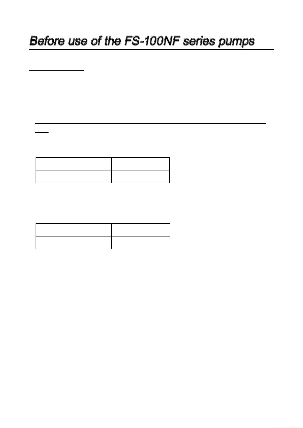
● The maximum stroke speed is limited for the prevention of bellows rupture.
See the table below.
Supply air pressure (MPa)
Max. stroke speed (spm)
0.196 - 0.686
100
● Differential pressure between supply air pressure and exhaust pressure is
limited for the prevention of bellows rupture. See below.
Supply air pressure (MPa)
Differential pressure (MPa)
0.196 - 0.686
0.41
Important Instruction
For the Safe and
Correct Handling of the pump
●
"Safety Instruction" section deals with important details about handling of the product. Before
the use of the pump, read this section carefully for the prevention of personnel injury or loss.
●
Observe the instructions accompanied with "WARNING" or "CAUTION" in this manual. These
instructions are very important for protecting pump users from dangerous situations.
●
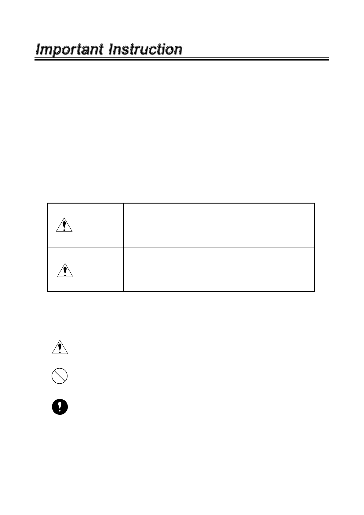
The symbols on this instruction manual have the following meanings:
Nonobservance or misapplication of the contents of
WARNING
“Warning” section could lead to a serious accident
which may result in death.
Nonobservance or misapplication of the contents of
CAUTION
“Caution” section could lead to a personal injury or
damage to the product.
Types of Symbols
Indicates that “Warning” or “Caution” must be exercised. Inside this triangle, a con-
crete and practical image provided as a warning or caution message is depicted.
Indicates a prohibited action or procedure. Inside or near this circle, a concrete and
practical image of the activity to be avoided is depicted.
Indicates an important action or procedure which must be performed or carried out
without fail. Failure to follow the instructions herein can lead to malfunction or
damage to the pump.
- 1 -
Safety section
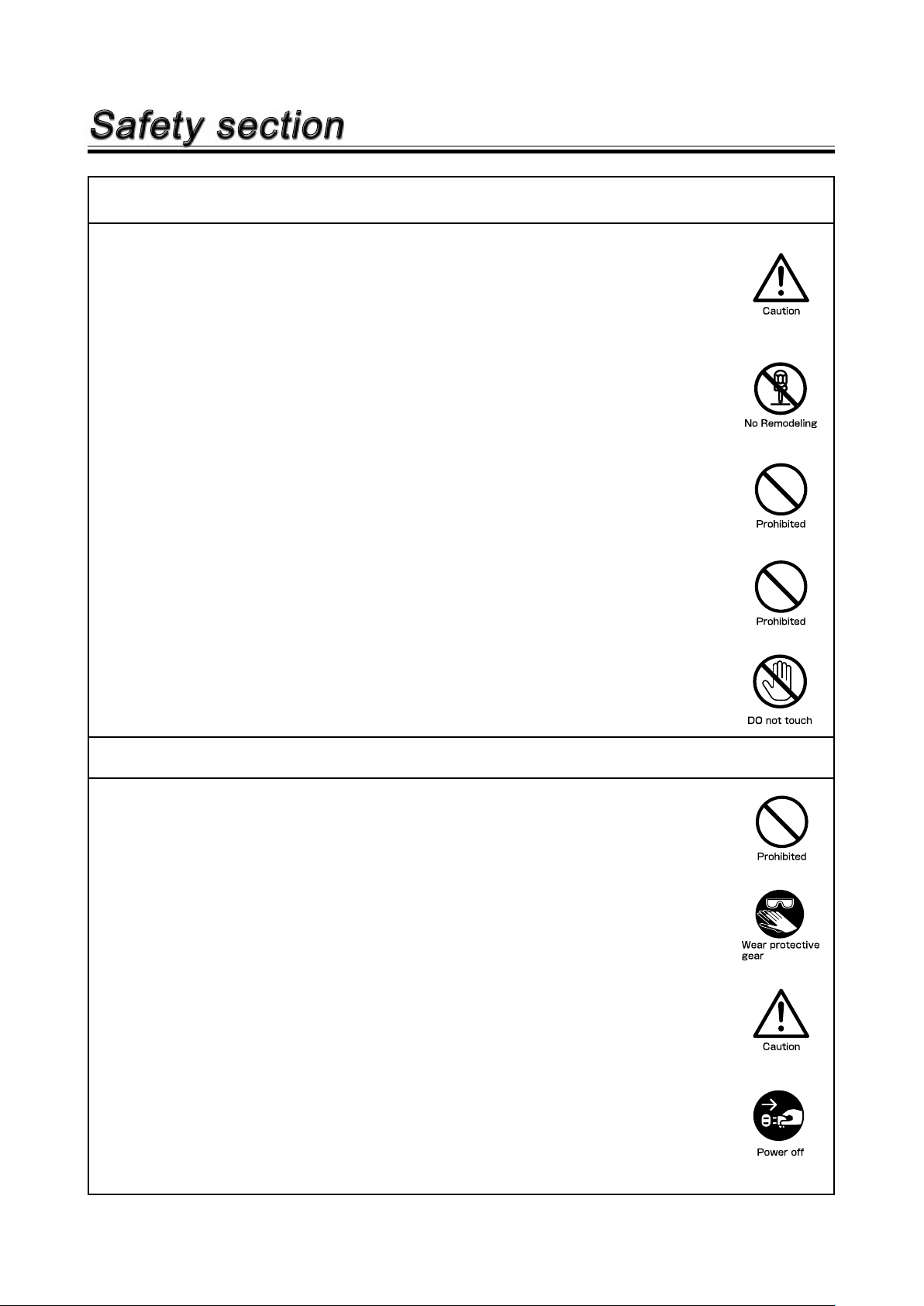
WARNING
●
Look around
Make sure there is no one around the pump when connecting the power
cable. Any power supply switch is not provided on the pump. Connecting
the power cable, the a solenoid valve starts to supply the air and the pump
starts to run.
●
Do not remodel the pump
Never remodel the pump. We are not responsible for any injury or damage
due to modification.
●
For specified application only
Use of the pump in any application other than those clearly specified may
result in injury or damage. Use the pump strictly in accordance with the
pump specifications and application range.
●
Do not drain
Do not drain chemicals directly onto the ground or a waste channel.
Disposal of chemicals should be in accordance with an applicable law.
●
Do not come in contact with the products
When the pump is sending a high temperature liquid of 50 deg.C or more,
the surfaces of the pump and piping become hot. Do not touch with the bare
hand. Wear protective gloves.
CAUTION
●
Do not exceed the specified voltage
Do not supply any power voltage other than specified one. Otherwise, a fire
or electric shock may result.
●
Wear protectors
Be sure to wear protective gear (protective goggles, cap, mask, acid-resistant gloves) when working on the pump. Rinse the pump with pure water in
advance.
●
Qualified operator only
The pump must be operated by operator(s) who has trained in the safe
operation of the pump.
●
Power OFF
Be sure to turn off the power before starting a maintenance/repair work.
Make sure no one turns on the power while working on the pump, otherwise
it may result in a serious accident. If your work field is noisy or dark, let other
people know about the situation by displaying a notice such as "POWER
OFF(Maintenance)" near the power switch.
- 2 -
Safety section
CAUTION
●
Storage limit
Risk of fire and/or health damage. Do not instal or store the pump in explosive atmosphere, dusty place, or corrosive gas (such as chlorine gas).
●
Keep ventilation
When handling a toxic liquid or odorant, keep your working site ventilation.
Always wear protective gear (protective mask, goggles, gloves, etc.).
●
Pump disposal
Any used or damaged pump must be disposed of in accordance with local
laws and regulations. Consult a licensed industrial waste products disposing
company.
●
Return
Before return drain a chemical from the pump and clean the inside with
water for safe transportation.
●
Stroke speed/Supply air pressure/Liquid temperature
The maximum stroke speed is 100spm at an air pressure between 0.196 -
0.686 MPa. Do not continuously run the pump beyond the operating range,
otherwise the pump may be deformed or damaged. The permissible liquid
temperature is between 5-60deg.C. Any operation beyond the permissible
liquid temperature can lead to the deformation of the bellows.
Supply air pressure range
Max. stroke speed
●
Permissible differential pressure in the bellows
Do not operate the pump continuously beyond 0.41 MPa. The life of bellows
may shorten.
Supply air pressure range
Differential pressure on bellows
●
Prohibited liquids
Do not operate the pump with the following liquid.
• Liquid easily crystallizes
• Liquid containing slurry
• Solvent naphtha
0.196 - 0.686 MPa
100 spm
0.196 - 0.686 MPa
0.41 MPa
●
Liquids to be handled with care
• Stripper
• Solvent-type liquid
• Fuming sulfuric acid
• Fuming nitric acid
- 3 -
Safety section
CAUTION
●
Static electricity
When low electric conductivity liquids such as ultra-pure water and fluor
inactive liquid (e.g. FluorinertTM) are handled, the static electricity may generate in the pump and may cause static discharge. Take countermeasures to
remove the static electricity.
●
Ambient temperature
Use this product between 0 - 40 deg.C. of surrounding temperature.
●
When stopping the pump
• Before stopping the pump, first release discharge side pressure.
Otherwise, the bellows may be deformed due to discharge side pressure.
• Do not close any valves right after stopping the pump. The resulting impact
pressure may deform the bellows or the connecting plate.
●
Pump at halt
• Do not supply air to both the right and left air-supply ports at the same time
to prevent the bellows from becoming deformed.
• Do not have the pump unused with any chemical in the bellows for a long
period. Some chemical can penetrate the bellows and corrode metal material.
●
Composite effective cross section area
Composite effective cross section area should be 43.5 mm2 or more.
●
Air exhaust port
Do not narrow the air exhaust port (for example by reducing the tube bore).
The residual pressure in the pump may deform the bellows.
●
During pump operation
• Make sure all the valves on both suction and discharge side piping are
open.
●
Note for the electrode
The electrode occasionally fails to detect leakage depending on operating
condition. Contact IWAKI for detail.
- 4 -

PRODUCT OUTLINE
1. Unpacking and Inspection ................. 6
2. Operating Principle ........................... 6
3. Identification Codes .......................... 7
4. Specifications .................................... 7
5. Outer Dimensions/Mass ................... 8
6. Names of Parts and
Structure of Pump ............. 9
7. Description on Body and Label ....... 10
- 5 -
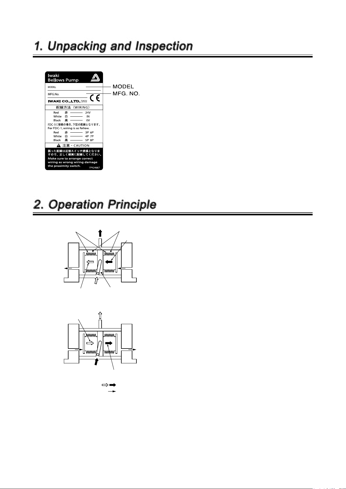
OUT
IN
Bellows Air chamber
Compression
Air supply
Pump head
Suction
Air exhaust
OUT
IN
Compression
Air supply
Suction
Air exhaust
: Liquid flow
: Air supply flow
Suction/compression: Created by bellows stroke
1. Unpacking and Inspection
After unpacking the product, check the following points to ascertain that the product is
exactly as you ordered. If you find anything
wrong, please contact your dealer.
[1] Does the model indicated on the nameplate
[2] Are there any transit damage?
[3] Are all optional items such as controller deliv-
[4] Regarding the quick exhaust valve, use alu-
2. Operation Principle
represent what you ordered?
ered with the pump?
minium one with the pressure resistance of
0.7MPa or more.
Our pneumatic drive pumps are designed for
semiconductor manufacturing and chemical dosing processes. And wet-ends are all
fluororesin.
The pump unit consists of two air chambers
and a pair of bellows. The bellows are reciprocated by supply air and make pumping action
continuously.
[1] A liquid is sucked into the pump head through
an inlet when the bellows expand (suction
motion).
[2] The liquid is then pumped through an outlet
when the bellows contract (discharge motion).
- 6 -- 6 -
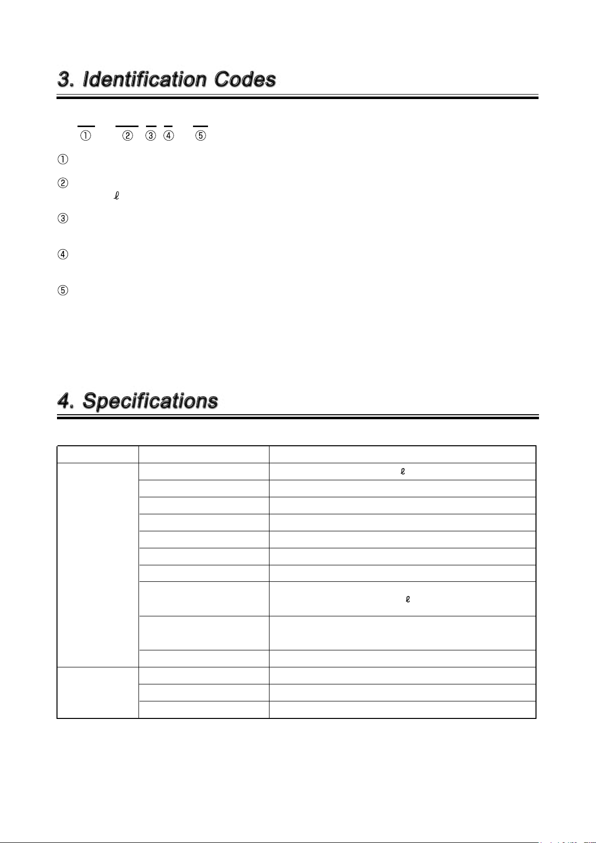
3. Identification Codes
FS - 100 N F - 01
Series code
Maximum discharge volume
100: 100 /min
Operating temperature
N: 5 - 60 deg.C
Pump connection port (discharge port/suction port)
F: Flange type connection (Standard)
Special specifications
No symbol: Standard
01 : Special specifications (01, 02······)
4. Specifications
Item Specifications
Max. discharge volume (Note 1)
Supply air pressure range 0.196-0.686 MPa
Max. stroke speed
Permissible differential pressure
Self-priming ability (Note 2) 1 m
General Specification
Proximity switch
arrangement
Pump connection por t JIS 20K 25A flange
Supply air connection port Rc 1/2"
Max. air consumption
(at max. discharge volume,
max. supply air pressure)
Liquid temp. range (deg.C) 5~60 deg.C
Ambient temp. 0~40 deg.C
Driving method External forced switching of driving air
Type High-frequency type proximity switch
Output NPN DC open/close output
Source voltage DC10V~DC30V
100 /min
100 spm
0.41 MPa
1495 N /min
Note 1. The maximum discharge volume is on pumping clean water at room temperature.
Note 2. The self-priming height is on pumping clean water at the maximum stroke speed at room temperature.
- 7 -
- 7 -
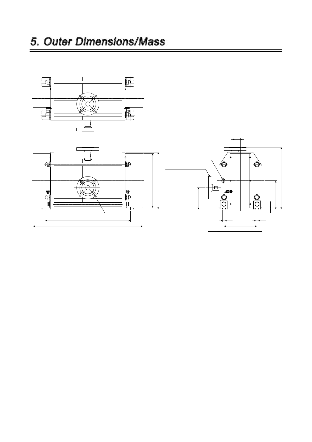
5. Outer Dimensions/Mass
13
13
185
240
(61)
119.5
30
475
612
302
317
158.5
6
344.5
4-ø19
2-JIS20K25A flange or equivalent
Air supply port 2-Rc1/2
FS-100NF Mass : 55.5kg
Unit : mm
- 8 -- 8 -
 Loading...