

IWAKI EWN-B16 VC, EWN-C16 VC, EWN-C21 VC, EWN-C31 VC, EWN-C36 VC Instruction Manual
...
2008 IWAKI CO., LTD.
Iwaki
Electromagnetic Metering Pump
EWN-R (Standard)
Safety instructions
Overview Installation Operation Maintenance Specication
Instruction manual
Thank you for choosing our product.
Please read through this instruction manual before use.
This instruction manual describes important precautions and
instructions for the product. Always keep it on hand for quick
reference.
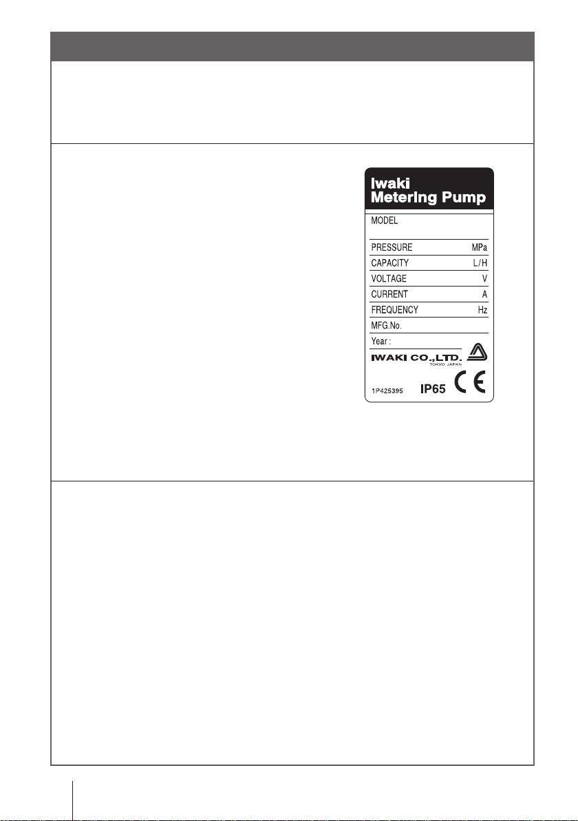
Order conrmation
After unpacking, check the following points. Contact us or your nearest
distributor if the delivery is imperfect.
a. Check if the delivery is as per order.
Check the nameplate to see if the information such as discharge capacity,
discharge pressure and power voltage
are as per order.
b. Check if the delivery is damaged or deformed.
Check for transit damage and loose bolts.
2
Order conrmation

Contents
Order conrmation ............................................................................................. 2
Safety instructions .......................................................................6
Warning ............................................................................................................. 7
Caution .............................................................................................................. 8
Precautions for use ........................................................................................10
Overview ......................................................................................12
Introduction .....................................................................................................12
Pump structure & Operating principle .........................................................12
Features .......................................................................................................14
Operational functions...................................................................................14
Part names.......................................................................................................19
Pump............................................................................................................19
Operational panel .......................................................................................20
Basic displays & Pump states ................................................................21
Identication codes ....................................................................................... 23
Pump/Drive units ........................................................................................ 23
Installation ..................................................................................25
Pump mounting .............................................................................................. 25
Pipework .........................................................................................................26
Tube connection ......................................................................................... 26
Check valve mounting ................................................................................ 28
Wiring .............................................................................................................. 30
Power voltage/Earthing .............................................................................. 30
Signal wire connection................................................................................ 32
Connections .......................................................................................... 34
Contents
3

Operation .....................................................................................37
Before operation .............................................................................................37
Points to be checked ...................................................................................37
Retightening of pump head xing bolts .......................................................37
Use of hexagon wrench instead of a torque wrench ............................. 38
Degassing ................................................................................................... 38
Flow rate adjustment ...................................................................................41
Stroke rate adjustment ...........................................................................42
Stroke length adjustment....................................................................... 44
Before a long period of stoppage (One month or more) ............................. 45
Operation programming ............................................................................... 45
Programming ow ....................................................................................... 46
Manual operation ........................................................................................ 48
EXT operation ............................................................................................. 49
EXT mode .............................................................................................49
EXT mode programming ....................................................................... 50
User mode ..................................................................................................59
STOP/Pre-STOP function .....................................................................60
STOP/Pre-STOP function cancellation ................................................. 62
OUTPUT function .................................................................................. 64
ANA-V/-R selection ...............................................................................66
Buffer ON/OFF selection ....................................................................... 68
PIN number entry ...................................................................................70
Keypad lock .................................................................................................72
Keypad lock activation ............................................................................73
Keypad lock release ...............................................................................73
Calibration mode .........................................................................................74
Unit change ..................................................................................................75
spm indication ..............................................................................................75
4
Contents

Maintenance ................................................................................76
Troubleshooting ............................................................................................. 77
Inspection ....................................................................................................... 79
Daily inspection ...........................................................................................79
Periodic inspection ......................................................................................79
Wear part replacement .................................................................................. 80
Wear part list ............................................................................................... 80
Before replacement .....................................................................................81
Valve set replacement .................................................................................81
Discharge valve set dismantlement/assembly .......................................81
Suction valve set dismantlement/assembly ..........................................83
Spacer set replacement (Auto degassing type) ....................................84
Air vent valve set replacement (Auto degassing type) .......................... 85
Diaphragm replacement .............................................................................85
Exploded view ................................................................................................ 88
Pump head, Drive unit & Control unit .........................................................88
Pump head ................................................................................................. 89
EWN-[B09•B11•B16•B21•C16•C21] [VC•VH•PC•PH•TC] ..................... 89
EWN-[B31•C31•C36] [VC•VH•PC•PH•TC] ............................................ 90
EWN FC .................................................................................................91
EWN C31PC/P6-V ................................................................................ 92
EWN SH/SH-H/SH-H2 .......................................................................... 93
EWN with an Automatic air vent ............................................................ 94
Specications/Outer dimensions ................................................................ 95
Specications .............................................................................................95
Pump unit ..............................................................................................95
Power cable ............................................................................................97
Pump colour ...........................................................................................97
Outer dimensions........................................................................................ 98
Contents
5
Safety instructions
Requirement
Read through this section before use. This section describes
important information for you to prevent personal injury or
property damage.
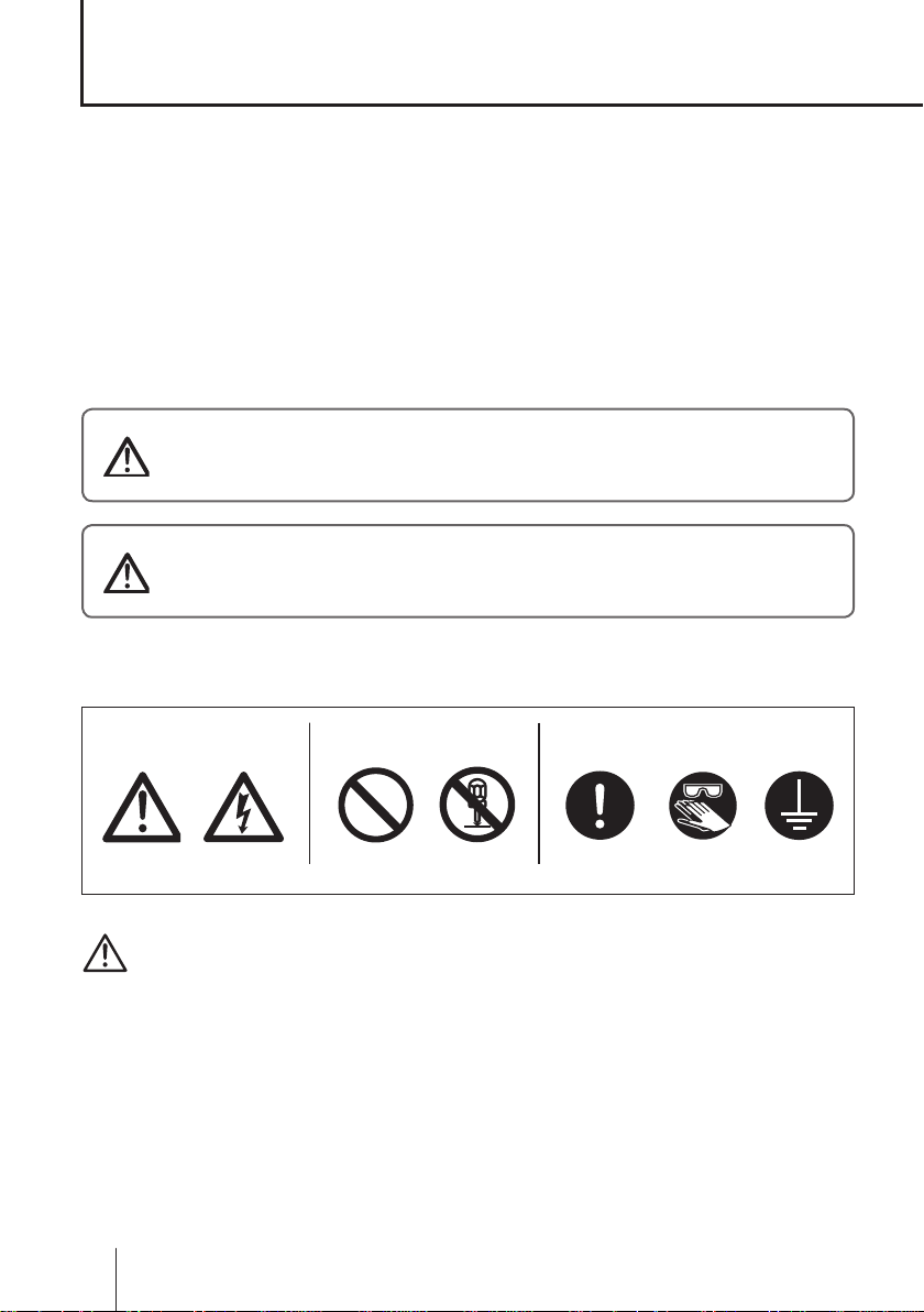
■ Symbols
In this instruction manual, the degree of risk caused by incorrect use is noted
with the following symbols. Please pay attention to the information associated
with the symbols.
WARNING
CAUTION
Indicates mishandling could lead to a fatal or
serious accident.
Indicates mishandling could lead to personal
injury or property damage.
A symbol accompanies each precaution, suggesting the use of "Caution", "Pro-
hibited actions" or specic "Requirements".
Caution marks Prohibited mark Requirement mark
Caution
Electrical
shock
Prohibited
Do not rework
or alter
Wear
protection
Grounding
Export Restrictions
Technical information contained in this instruction manual might be treated
as controlled technology in your countries, due to agreements in international
regime for export control.
Please be reminded that export license/permission could be required when this
manual is provided, due to export control regulations of your country.
6
Safety instructions
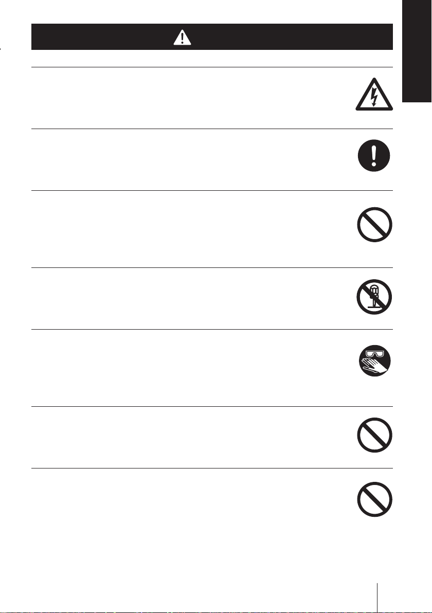
WARNING
shock
Turn off power before work
Risk of electrical shock. Be sure to turn off power to stop the pump
and related devices before work.
Stop operation
On sensing any abnormality or danger, suspend operation immedi-
ately and inspect/solve problems.
Do not use the pump in anything other than a specied purpose
The use of the pump in any purpose other than those clearly speci-
ed may result in failure or injury. Use this product in a specied
condition.
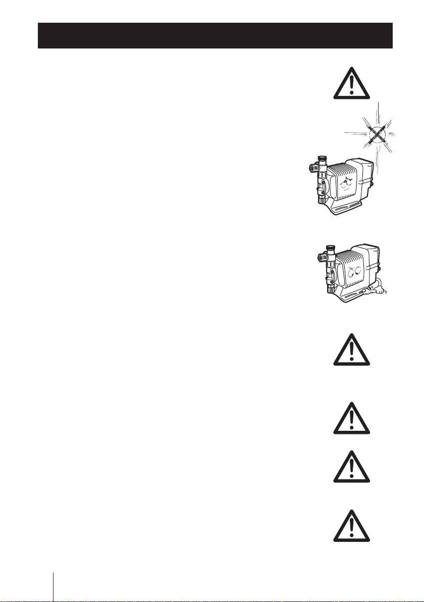
Do not modify the pump
Remodelling the pump carries a high degree of risk. We are not
responsible for any failure or injury results from remodelling.
Safety instructions
Electrical
Requirement
Prohibition
Do not remodel
Wear protective clothing
Always wear protective clothing such as an eye protection, chemi-
cal resistant gloves, a mask and a work cap during dismantlement,
assembly or maintenance work.
Do not damage a power cable
Do not pull or knot a power cable or place a heavy stuff on it. Dam-
age to the cable could lead to a re or electrical shock.
Do not use the pump in a ammable atmosphere
Do not place dangerous or ammable goods near the pump for your
safety.
protectors
Prohibition
Prohibition
WARNING
Wear
7
CAUTION
A qualied operator only
The pump must be handled or operated by a qualied person with a
full understanding of the pump. Any person who is not familiar with
this product should not take part in operation or management.
Use a specied power only
Do not apply any power other than the one specied on the nameplate.
Otherwise, failure or re may result. Also, be sure to earth the pump.
Do not run pump dry
Do not run pump dry for more than 30 minutes (even when the
pump runs for degassing). Otherwise, the pump head xing screws
may loosen and liquid may leak. Optimise your system in order for
the pump not to run dry. If the pump runs dry for a long period (for
more than 30 minutes), the pump head and the valve cases may
deform by friction heat and consequently leakage results.
Requirement
Prohibition
Caution
Do not wet electric parts or wiring
Risk of re or electrical shock. Install the pump free from liquid spill.
Observe an applicable MSDS
Take account of installation environment. Chemicals should be
controlled in accordance with a MSDS.
Do not install or store the pump in the following places where...
• Under a ammable atmosphere or in a dusty/humid place.
• Ambient temperature exceeds 40ºC or falls below 0ºC.
• Under direct sunlight or wind & rain.
Countermeasure against efux
Take protective measures against an accidental chemical overow
results from pump or piping breakage.
8
CAUTION
Prohibition
Caution
Prohibition
Requirement

Do not use the pump in a water place
Requirement
Caution
Caution
The pump is not totally waterproof. The use of the pump in water or
high humidity could lead to electrical shock or short circuit.
Earthing
Risk of electrical shock. Always earth the pump.
Install an earth leakage breaker
An electrical failure of the pump may adversely affect related devices. Purchase and install an earth leakage breaker separately.
Wear part replacement
Follow instructions in this manual for wear part replacement. Do not
dismantle the pump beyond the extent of the instructions.
Do not use a damaged pump
Using a damaged control unit could lead to an electric leak or shock.
Safety instructions
Prohibition
Earthing
Prohibition
Disposal of the used pump
Dispose of any used or damaged pump in accordance with relevant regulations. Consult a licensed industrial waste products disposing company.
Tighten the pump head
Liquid may leak if pump head xing bolts are loose. Tighten the
bolts evenly to the following torque in diagonal order before initial
operation. Periodically retighten them for the prevention of leakage.
Tightening torque
EWN - B11 /-B16/-B21/-C16/-C21 : 2.16 N•m
EWN-B31/-C31/-C36 : 2.55 N•m
Solution compatibility
This pump has been evaluated for use with water only. The suitability of this pump for use with liquids other than water, such as acid
and alkaline, is the responsibility of the user. For liquids other than
water, select the best-suited liquid end material combination using a
chemical compatibility chart.
Requirement
Caution
CAUTION
9
Precautions for use
• Electrical work should be performed by a qualied opera-
tor. Otherwise, personal or property damage accident may
result.
• Do not install the pump in the following places where...
–Under a ammable atmosphere or in a dusty/humid place.
–Under direct sunlight or wind & rain.
– Ambient temperature exceeds 40ºC or falls below 0ºC.
Protect the pump with a cover when installing it out of
doors.
• Select a level location where is free from vibration and liq-
uid can't stay. Anchor the pump with M5 bolts so as not to
vibrate. If the pump is installed at a tilt, a ow may reduce.
• When two or more pumps are installed, the pump opera-
tion interacts each other and vibration becomes signicant,
resulting in poor performance or failure of internal electri-
cal devices. Select an installation location where tolerates
vibration to enough degree.
Caution
Caution
• Keep an ample working area around the pump for inspec-
tion and maintenance.
• Install the pump as close to a supply tank.
• Install the pump in a cool and dark place when handling
liquids that readily generate gas bubbles such as sodium
hypochlorite or hydrazine solution. Flooded suction applica-
tion is strongly recommended for these liquids.
10
Precautions for use
Caution
Caution
Caution
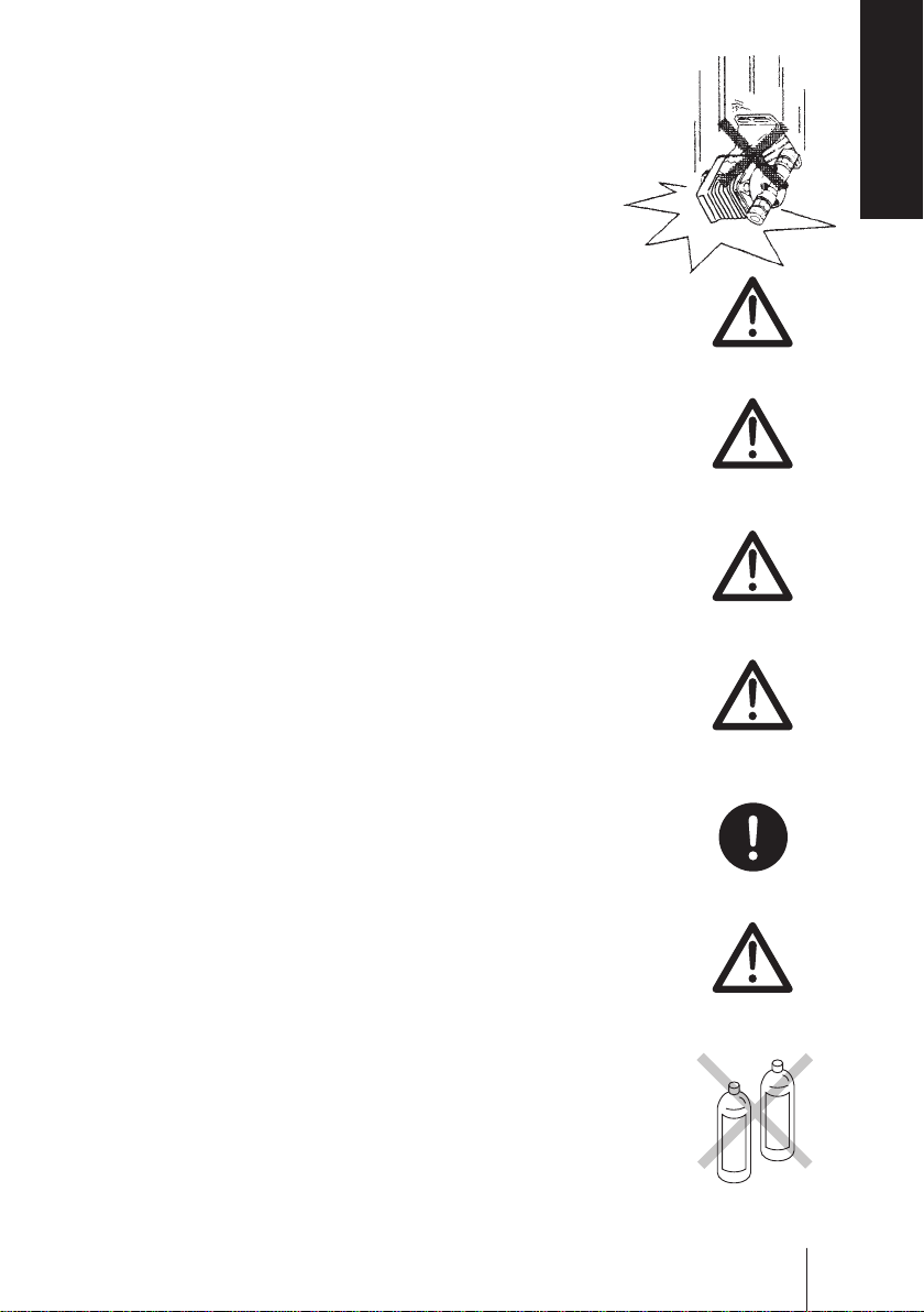
• Be careful not to drop the pump onto the oor. A strong
impact may reduce pump performance. Do not use a pump
which has once damaged. Otherwise an electrical leak or
shock may result.
• The pump is a light water-/dust-proof structure of IP65, but
is not totally waterproof. Do not have the pump wet with the
liquid handled or rainwater.
• Never wet the pump head, control unit and drive unit. Oth-
erwise, failure or an accident may result. Immediately wipe
off liquid if the pump has got wet.
• Do not close a discharge line during operation. Otherwise,
liquid may leak or tubing may break.
Safety instructions
Caution
Caution
Caution
• Do not remove the control unit. Note that an applicable con-
trol unit differs with each drive unit. Do not attach a control
unit to a different drive unit. Otherwise, an electrical circuit or
the drive unit may fail.
• Release pressure from a discharge line before dismantling
the pump or removing tubing. Otherwise, chemical liquid
gushes out.
• Be careful not to come in contact with residual liquid.
• Do not clean the pump or nameplate with a solvent such
as benzine and thinner. This may discolour the pump or
erase printing. Use a dry cloth or a wet cloth with water
or neutral detergent.
Precautions for use
Caution
Requirement
Caution
Thinner
Benzine
11
Overview
The information such as characteristics, features and part
names are described in this section.
Introduction
Pump structure & Operating principle
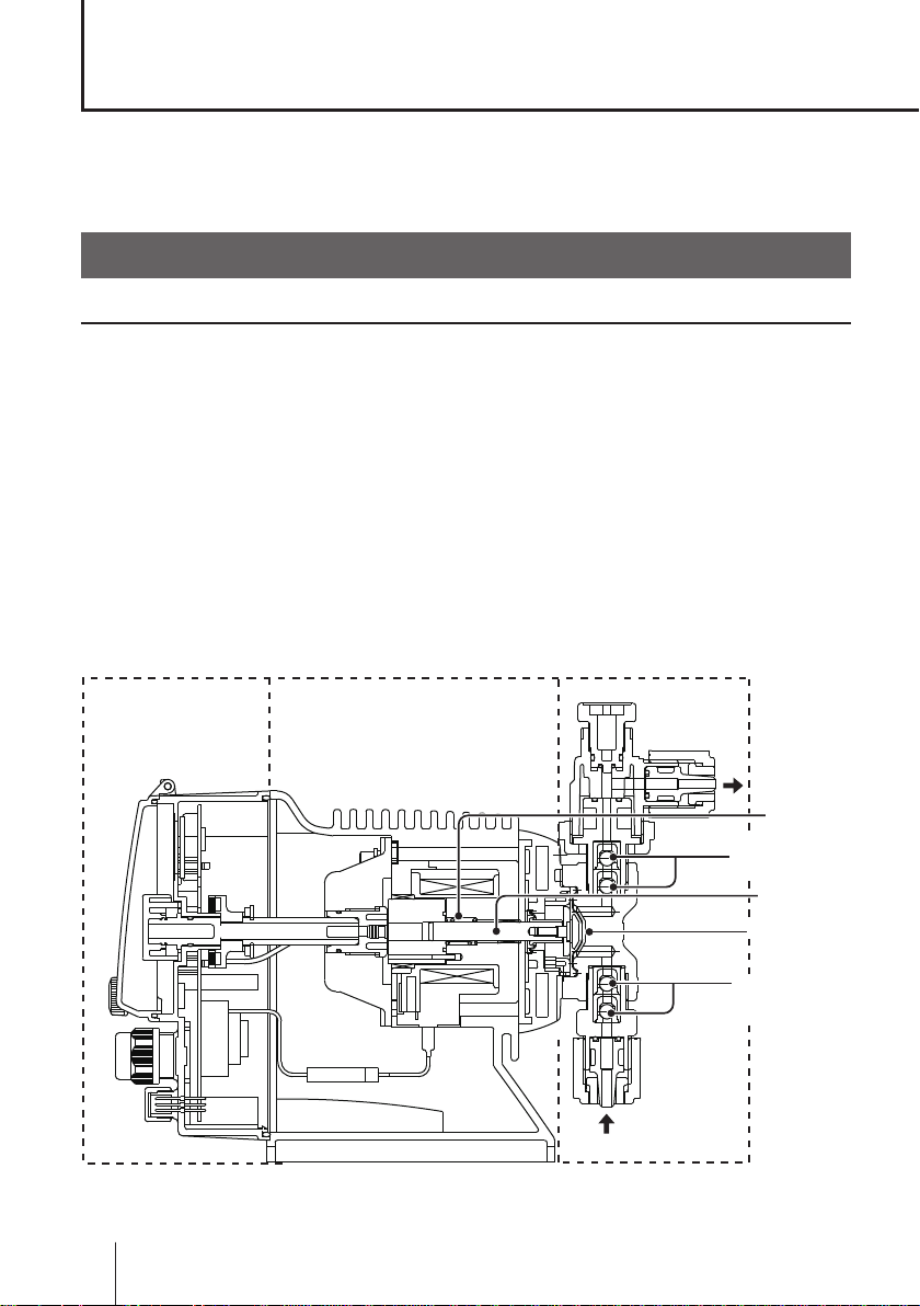
The EWN series is a diaphragm metering pump which consists of a pump
head, drive unit and control unit. A diaphragm is directly driven by electromagnetic force.
Principle of operation
The pulse signal controls the electromagnetic force and spring force in order
to make reciprocating motion. The reciprocating motion is transferred to a
diaphragm through a plunger and then volumetric change occurs in the pump
head. This action transfers liquid along with pump head valve action.
Control unit Pump headDrive unit
12
Introduction
OUT
Spring
Pump head valve
(Discharge side)
Plunger
Diaphragm
Pump head valve
(Suction side)
IN
● Auto degassing system
Discharge port Air vent port
AIR
OUT
Automatic air
vent valve body
LOCK
Pump head valve
Air vent valve
Pump head
Suction port
• Once air is entrained through the suction port, the working pressure difference
between the pump head valve and the air vent valve separates entrained air
from liquid.
• Entrained air is expelled to open air through the automatic air vent valve body.
• Only liquid is delivered to a discharge line through the discharge port. Note a
small amount of liquid is expelled with entrained air.
Overview
Introduction
13
Features
Pump operation
● Multivoltage operation
The EWN-R series is a multivoltage type (100-240VAC) and can be selected
without concern for local power voltage.
● High turndown ratio
Digitally-controlled stroke rate range is 0.1-100%. The stroke length shifts for
a ne ow adjustment.
● Waterproof and dustproof structure (IP65)
With the aim of improving resistance to exposure to liquid, the control unit is
installed on the back of the pump and the control panel is protected with a
cover as standard equipment. A rubber gasket is provided between the pump
head and the bracket to prevent water from entering from the periphery of
the pump head.
* This pump is not completely water resistant. Protect the pump with a cover when
installing it out of doors.
Operational functions
● Manual operation (see page 48)
The start/stop of the pump by key operation
Key operation
(Push key)
*Manual operation can be done at any time during operation or stop.
● EXT operation (see page 49)
The pump operation by the external signal.
The external operation is available after multiplier or divisor programming.
14
Introduction
Run Run
Stop
Stop
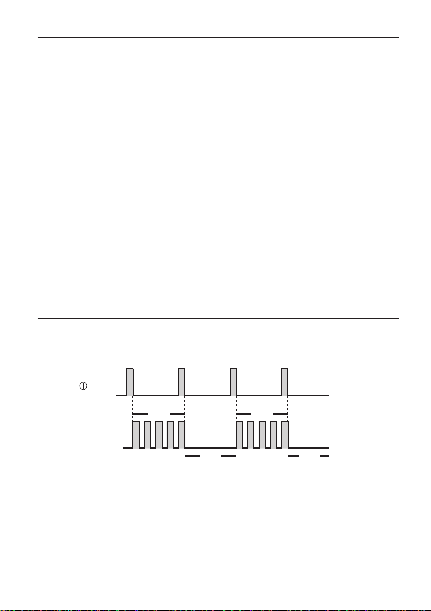
Multiplier programming (See page 51)
1-9999 shots can be programmed to one pulse signal.
*In the EXT operation, the pump runs at the manual operation stroke rate.
*The pump makes one shot per pulse when the multiplier is programmed to 1.
Example) When the multiplier is programmed to 5, the pump makes ve
shots per signal.
Pulse signal input
Pump operation
1 2 3 4 5 1 2 3 4 5
A buffer works when the pump receives an external signal before the pro-
grammed shots per signal is completed.
Pulse signal input
Pump operation
1 2 3 4 5 1 2 3 4 5 1 2 3 4 5 1 2 3
*The buffer stores the external signals for up to 65535 shots.
Overview
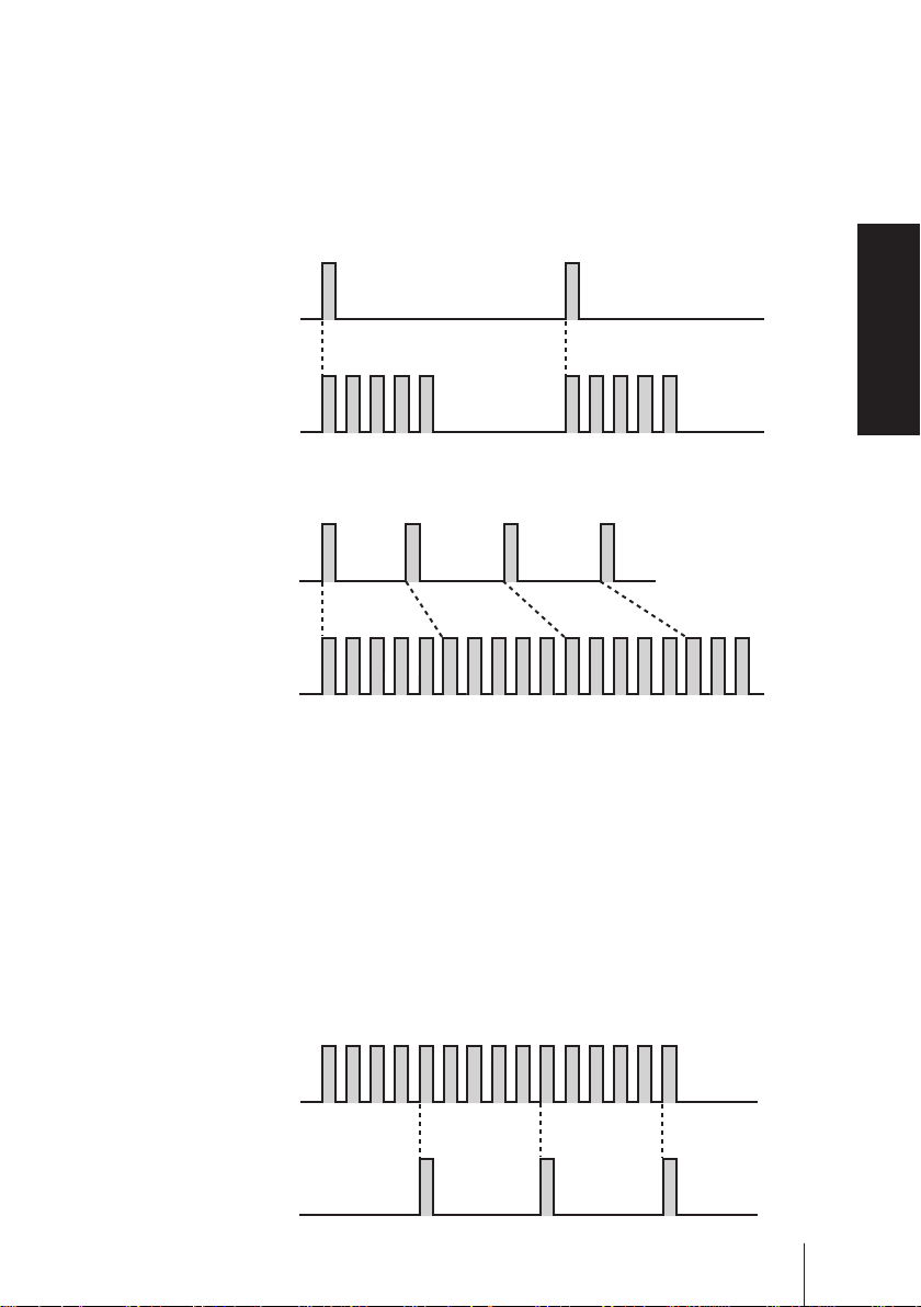
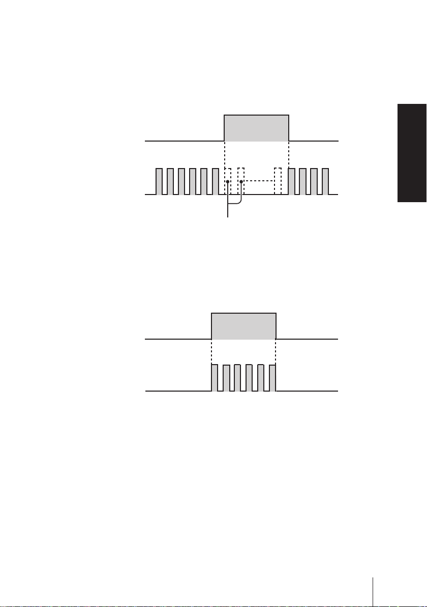
Divisor programming (See page 53)
1-9999 pulse signals can be programmed to make one shot.
* The pump can not run over a programmed stroke rate (max. 100%) even if a divisor
is set to run the pump faster.
*The pump makes one shot per pulse when a divisor is programmed to 1.
Example) When a divisor is programmed to 5, the pump makes one shot per
5-signal.
Pulse signal input
1 2 3 4 5 1 2 3 4 5 1 2 3 4 5
Pump operation
Introduction
15
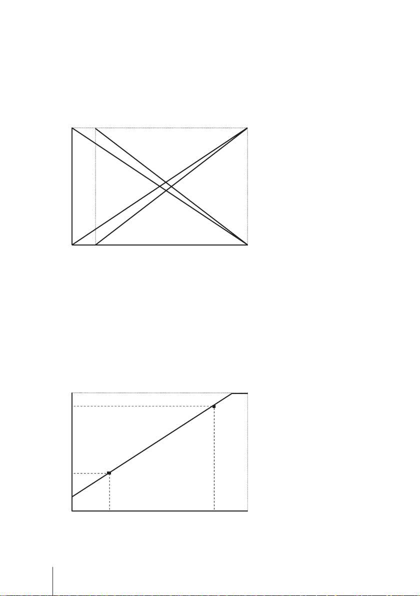
ANA. R (analogue rigid) programming (See page 57)
The pump increases/decreases a flow rate in proportion to 0-20mA. Four (4-
20, 20-4, 0-20, 20-0) programs are provided.
In "4-20" or "20-4" program a disconnection sensor works to stop the pump
as a current value falls below 4mA ("DISCN" blinks on the screen). Check
wiring as necessary. Pushing the start/stop key, this state is released.
100%
0 4
b
d
c
a
20mA
Condition
The left graph is in the following
programs.
a. 4-20 (Default setting)
b. 20-4
c. 0-20
d. 20-0
ANA. V (analogue variable) programming (See page 55)
The pump increases/decreases a flow rate in proportion to 0-20mA.
Setting two points can draw a straight line. Depending on the position of the
two points, 0 % may not come at 0mA in some cases. When a stroke rate
could become over 100% at some mA due to the setting, pump speed is lim-
ited to 100%.
100%
85
P2
Condition
The left graph is in the following
setting.
P1 = 6 mA, 30%
P2 = 17 mA, 85%
30
0 6
16
Introduction
P1
20mA
17
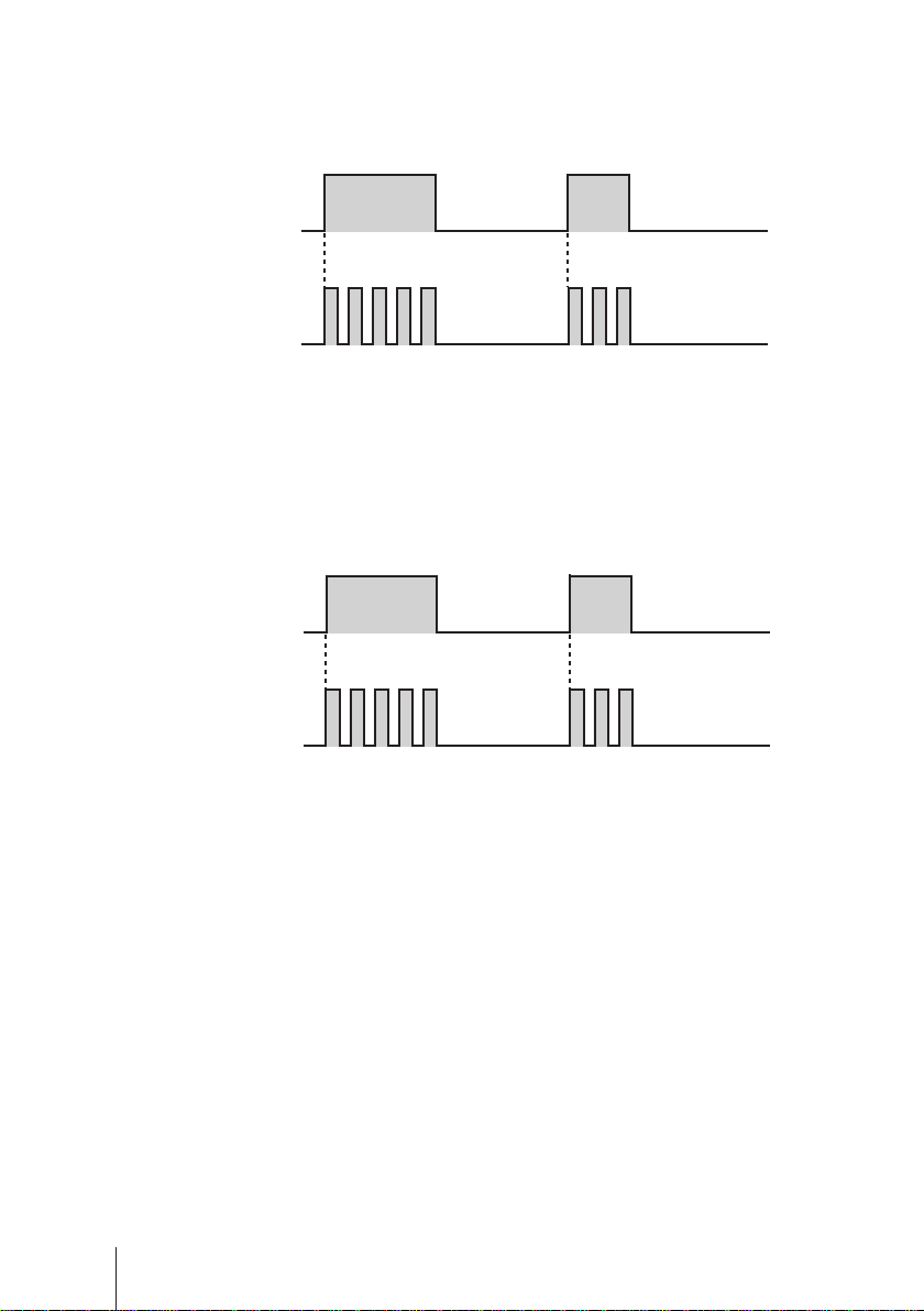
● STOP function (See page 60)
The start/stop of the pump can be controlled by the external signal.
When "NOR. OP" is selected...
The pump stops while receiving the external signal via the STOP terminal.
*The pump resumes operation when the STOP signal is released.
STOP signal input
Run Run
Pump operation
Stop
The pump stops running while
the STOP signal is inputted.
When "NOR. CL" is selected...
The pump runs while receiving the external signal via the STOP terminal.
*The pump stops operation when the stop signal is released.
STOP signal input
Run
Pump operation
Stop Stop
Overview
● Pre-STOP function (See page 60)
When "NOR. OP" is selected...
The STOP LED lights orange while the pump is receiving the external signal
via the Pre-STOP terminal (a contact is closed). Note the pump does not
stop running.
When "NOR. CL" is selected...
The STOP LED stops lightening while the pump is receiving the external
signal via the Pre-STOP terminal (a contact is closed).
Introduction
17
● AUX function (See page 40)
The pump runs at the maximum stroke rate while receiving the external sig-
nal via the AUX terminal. Use this function for degassing.
Pulse signal input
Pump operation
1 2 3 4 5 1 2 3
● Priming function (See page 40)
The pump runs at the maximum stroke rate while both the UP and DOWN
keys are pressed. Use this function for degassing.
Press Press
▲+▼ keys
Pump operation
1 2 3 4 5 1 2 3
● OUTPUT function (See page 64)
Signals can be sent via the output terminal in sync with manual operation.
The terminal can be set to on or off.
18
Introduction
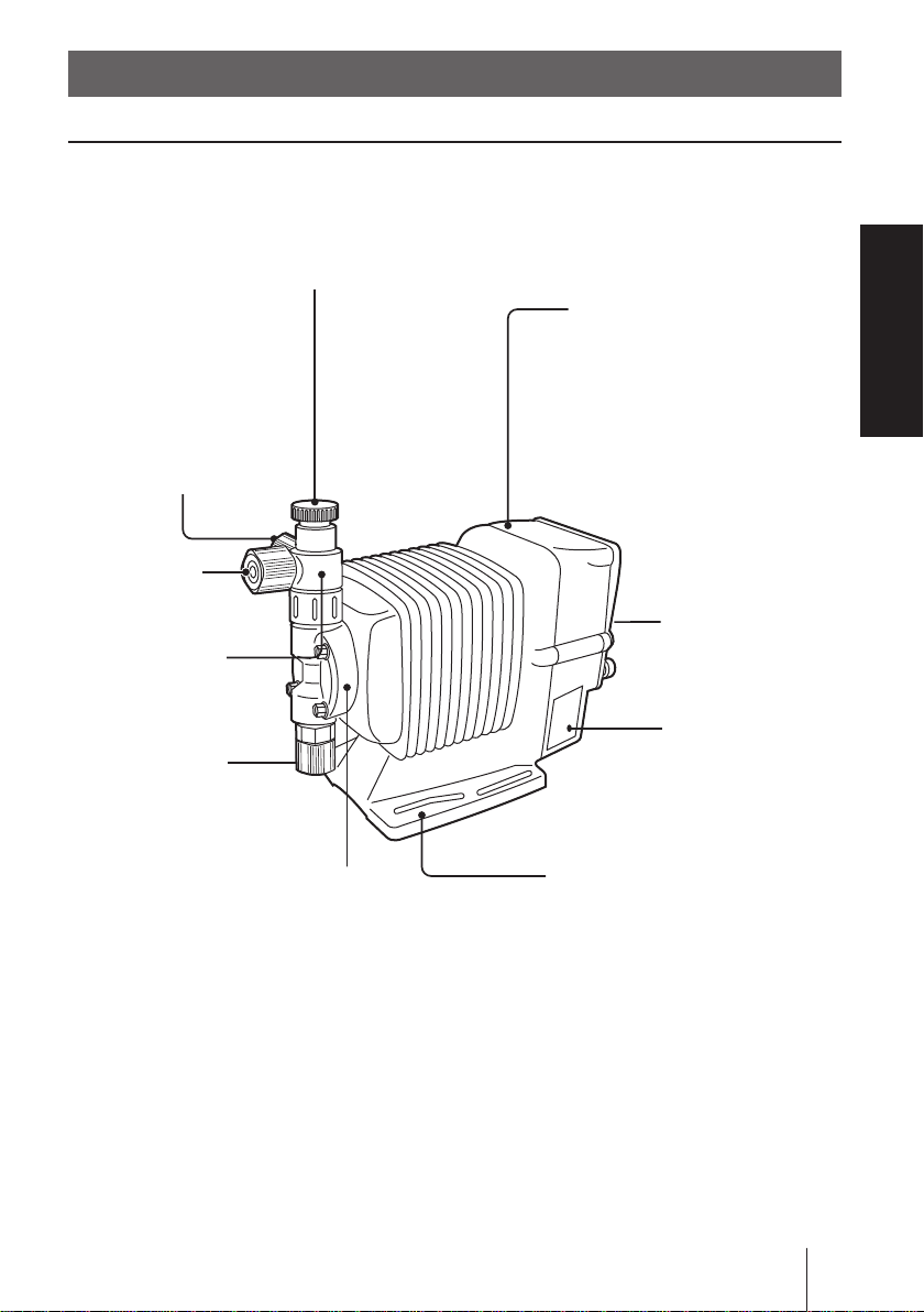
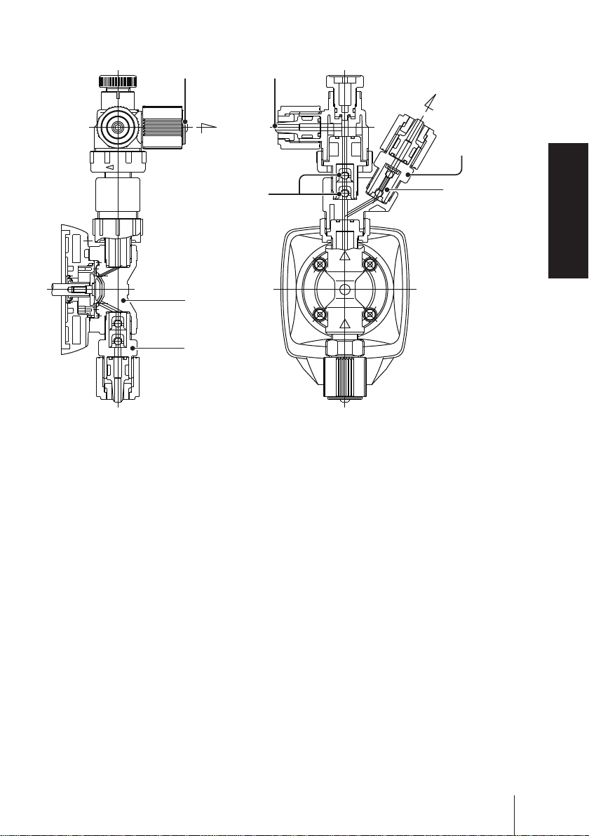
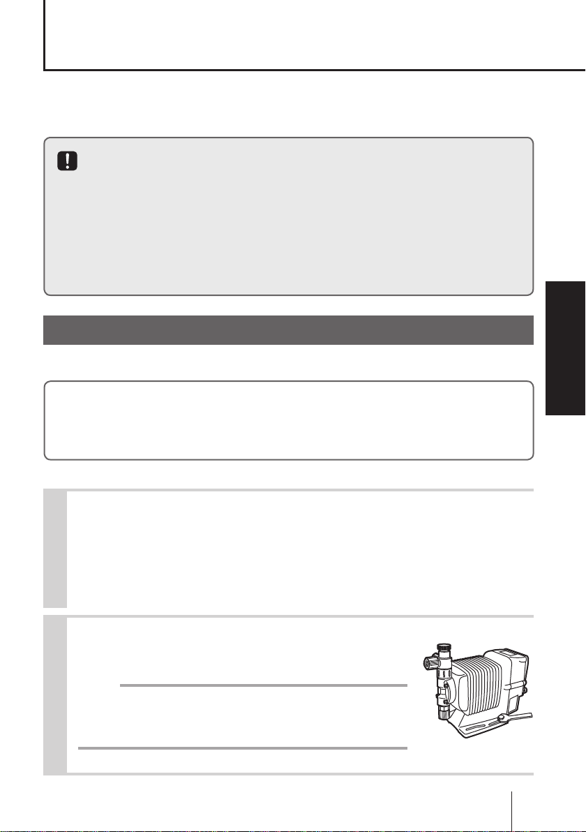
Part names
Pump
Adjusting screw
Used for opening the air vent port.
Air vent por t
Always connect a tube.
Be sure to return the tube
end to a supply tank or a
cont ainer.
The air vent port can
rotate 90 degrees.
Outlet
Air vent body
Inlet
Pump head
Overview
Control unit
Used for the start/stop of the
pump and stroke rate adjustment/programming.
Stroke length
adjusting knob
Used for adjusting
a flow rate.
Nameplate
Describes the
pump specifications.
Base
Always fix with bolts.
Part names
19
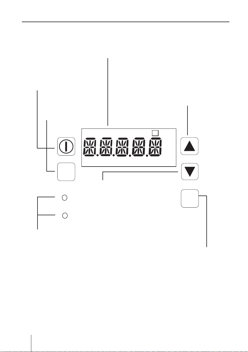
Operational panel
Display
An operational status, a selected mode and
a programmed value are shown here.
START/STOP key
Used for starting/stopping
the pump operation.
EXT key
Used for entering the
EXT mode.
UP key
Used for increasing numeric values or selecting a programming
mode.
MAN DIV MULT ANA. RV P
OVER P1 2 LOCK Err Disp SET
EXT
DOWN key
Used for decreasing numeric
values or selecting a program-
ON
STOP
LED
Lights as the pump is turned
on and blinks at each shot.
ming mode.
!
spm
L/h
mA
DISP
DISP key
Used for checking flow information or changing units.
20
Part names
■
MULT
ANA. R
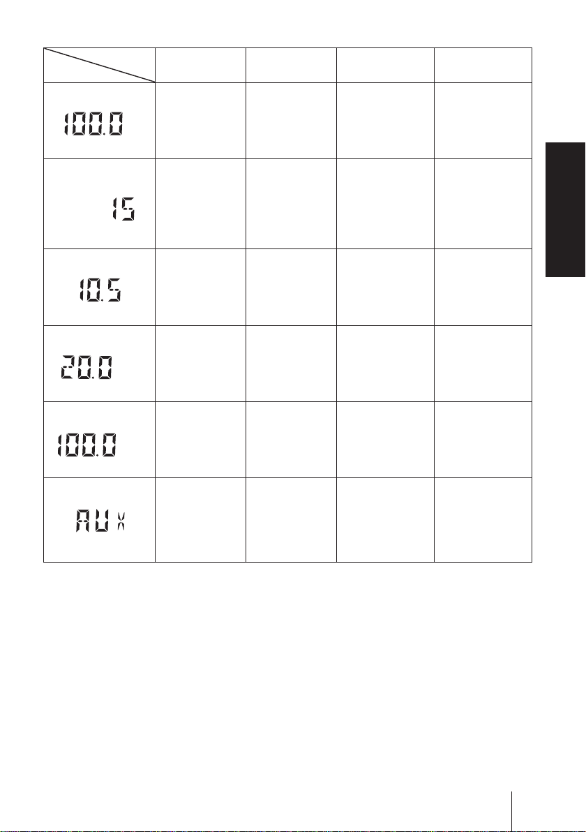
Basic displays & Pump states
STOP LED
lights red
MAN
%
DIV
― ―
%
%
ANA. V
%
―
― ―
― ―
― ―
― ― ―
ON LED lights
orange
Manual wait
state. Display
shows stroke
rate in %.
ON LED lights
green
―
EXT(Multiply)
mode. The
pump is waiting
for the external
signal.
EXT(Divide)
mode. The
pump is waiting
for the external
signal.
EX T(ANA.
R) mode. The
pump is waiting.
EX T(ANA.
V) mode. The
pump is waiting.
ON LED blinks
green
The pump
is running in
manual mode.
Display shows
stroke rate in %.
EXT(Multiply)
mode. The
pump is making
the displayed
# of shots per
signal.
EXT(Divid e)
mode. The
pump is running
at the displayed
stroke rate.
EX T(ANA.
R) mode. The
pump is running
at the displayed
stroke rate.
EX T(ANA.
V) mode. The
pump is running
at the displayed
stroke rate.
AUX mode.
The pump
is running at
the maximum
stroke rate.
Overview
Part names
21
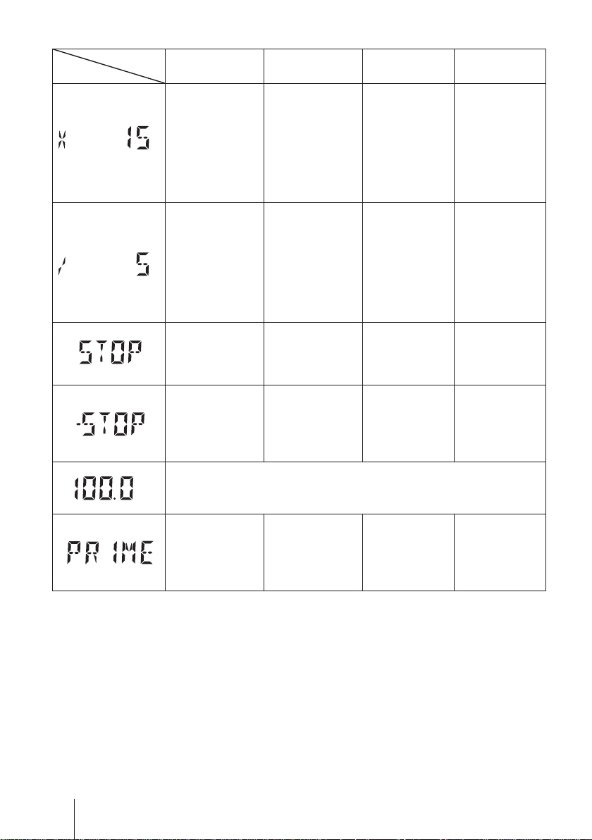
STOP LED
LOCK
SET
MULT
lights red
ON LED lights
orange
ON LED lights
green
ON LED blinks
green
EXT(Multiply)
programming
mode. The
SET
―
pump is set
to make the
displayed #
― ―
of shots per
signal.
EXT(Divid e)
programming
DIV
―
mode. The
pump is set
to make one
― ―
shot for the
displayed # of
signals.
Operation stop
by the STOP
signal. ON LED
― ― ―
lights green.
STOP signal
input in the
manual wait
― ― ―
state. ON LED
lights orange.
MAN
Keypads are locked. Keypad operation is ineffective in this state.
Release keypad lock before operation.
%
22
Part names
PRIME mode.
The pump
― ― ―
is running at
the maximum
stroke rate.
Identication codes
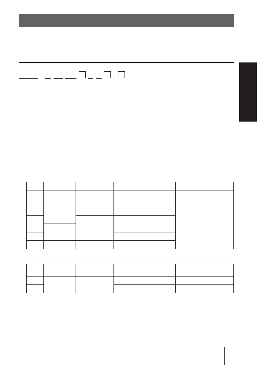
The model codes of the pump/drive units and the control unit represent the following information.
Pump/Drive units
EWN - B 11 VC
E R -
a b c d e f g h i
a. Series name
EWN: Multivoltage electromagnetic metering pump
b. Drive unit (Average power consumption)
B: 20W
C: 24W
c. Diaphragm effective diameter
09: 8mm 11: 10mm 16: 15mm
21: 20mm 31: 30mm 36: 35mm
d. Wet end materials
Code Pump head Valve O ring Valve seat Gasket Diaphragm
VC
VH HC276 EPDM EPDM
PC
PH HC276 EPDM EPDM
FC
TC FKM FKM
SH SUS316 HC276 SUS316
PVC
GFRPP
PVDF CE
CE FKM FKM
CE FKM FKM
PCTFE
―
―
PTFE
Overview
PTFE
+ EPDM
Automatic air vent (Auto degassing type)
Air vent valve
Code
VC
VH HC276 HC276 EPDM EPDM
guide A
PVC PVC
Material code
PVC : Transparent polyvinyl chloride GFRPP :
PVDF : Polyvinylidene diuoride EPDM : Ethylene-propylene rubber
FKM : Fluorine-contained rubber PTFE : Polytetrauoroethylene
HC276 : HASTELLOY C276 SUS316 : Austenite stainless steel
CE : Alumina ceramics PCTFE : Polymonochlorotriuoroethyle
Air vent valve
guide B
Valve Separate pin Valve seat O ring
CE Titanium FKM FKM
Glassber-reinforced polypropylene
Identication codes
23

e. Tube connection bore
No. Hose size (ID×OD) Wet end materials Pump model
ø4×ø6*²
ø6×ø8*²
ø9×ø12 VC/VH/PC/PH EWN-31 & -36
ø10×ø12 TC EWN-31 & -36
No
code*¹
1 ø4×ø9
2 ø4×ø6
3 ø6×ø8
4 ø8×ø13 VC/VH/PC/PH EWN-31 & -36
6 ø10×ø12 VC/VH/PC/PH EWN-31 & -36
7 ø1/4"×ø3/8 "
8 ø3/8"×ø1/2" VC/VH/PC/PH/TC EWN-31 & -36
9 Rc1/4 VC/VH/PC/PH/TC/VC-C/VH-C
23 ø6×ø12 VC EWN -11/-16/-21/-31 & -36
24 ø5×ø8 VC/TC/VC- C EWN-09/-11/-16 & -21
1/27
2/27
3/27
7/27
ø6×ø12 VC-C/VH-C EWN-09/-11/-16 & -21
Rc 1/4 FC/SH/SH-H/SH-H2 EWN-11/-16/-21/-31 & -36
IN: ø15×ø22
OUT: ø9×ø12
IN/AIR: ø4×ø6*²
OUT: R1/4
IN/AIR: ø6×ø8*²
OUT: R1/4
IN: ø4×ø9
OUT: R1/4
IN: ø4×ø6
OUT: R1/4
IN: ø6×ø8
OUT: R1/4
IN: ø1/4"×ø3/8"
OUT: R1/4
*¹ ø4×ø6 and ø6×ø12 are equipped to the EWN-09/-11/-16/-21 (VC-C type).
*² European standard hose size is ø4×ø6. Australian standard hose size is ø6×ø8
(VC/VH/PC/PH/TC/VC-C/VH-C/VC-A/VH-A).
VC/VH/PC/PH/TC/VC-C/VH-C/
VC-A/VH-A
VC/VH/PC/PH/TC/VC-C/VH-C/
VC-A/VH-A
PC/P6-V EW N-31
PC/PH-H/PH-H2 EWN-11 & -16
PC/PH-H/PH-H2 EWN-11 & -16
VC/VH/PC/PH/VC-C/ VH-C/
VC-A/VH-A
VC/VH/PC/PH/VC-C/ VH-C/
VC-A/VH-A
VC/VH/PC/PH/TC/VC-C/VH-C/
VC-A/VH-A
VC/VH/PC/PH/TC/VC-C/VH-C/
VC-A/VH-A
PC/PH-H EWN-11 & -16
PC/PH-H EWN-11 & -16
PC/PH-H EWN-11 & -16
PC/PH-H EWN-11 & -16
EWN-09/-11/-16 & -21
EWN-09/-11/-16 & -21
EWN - 09 /-11/-16 & -21
EWN-09/-11/-16 & -21
EWN-09/-11/-16 & -21
EWN-09/-11/-16 & -21
EWN-09/-11/-16/-21/-31 & -36
f. Power cable
E: European type A: Australian type
g. Control unit function
R: Standard
h. Special version
C: High compression type H: High pressure type
V: High viscosity type A: Auto degassing type
i. Special conguration
H: High pressure type (2MPa)
24
Identication codes
Installation
This section describes the installation of the pump, tubing and
wiring. Read through this section before work.
Observe the following points when installing the pump.
• Be sure to turn off power to stop the pump and related devices before work.
• Upon sensing abnormality or danger, stop work immediately. Remove
problems before resuming work.
• Do not place dangerous or ammable goods near the pump for your safety.
• Risk of an electrical leak or shock. Do not use a damaged pump.
Pump mounting
Select an installation location and mount the pump.
Necessary tools
• Four M5 bolts (pump mounting)
• Adjustable wrench or spanner
Installation
Select a suitable place.
1
Always select a at oor free of vibration. See page 10 for detail.
Flooded suction is recommended when handling a gaseous liquid such
as sodium hypochlorite.
Anchor the pump by the M5 bolts.
2
Be sure to x the pump at four points.
NOTE
Install the pump horizontally. If the pump is installed at a
tilt, a ow may reduce.
Pump mounting
25

Pipework
Connect tubes to the pump and install a check valve.
Before operation
• Cut the tube ends at.
Necessary tools
• Adjustable wrench or spanner
Tube connection
a. Pass a tube into the tting nut and
hose stopper and then slide it down to
the hose adapter as far as it will go.
b. Fit the tube end (hose adapter) to the
tting. Then hand tighten the tting nut.
c. Retighten the tting nut by turning it
180 degrees with an adjustable wrench
or spanner.
* The plastic tting nut may be broken if it is
tightened too much.
Tube end (Side view)
Tube
Fitting nut
Hose
stopper
Slide it
down
Hose
adapter
Fitting
Connect tubes into the inlet and
1
outlet.
26
Pipework
Tube
Tube
Outlet
Inlet
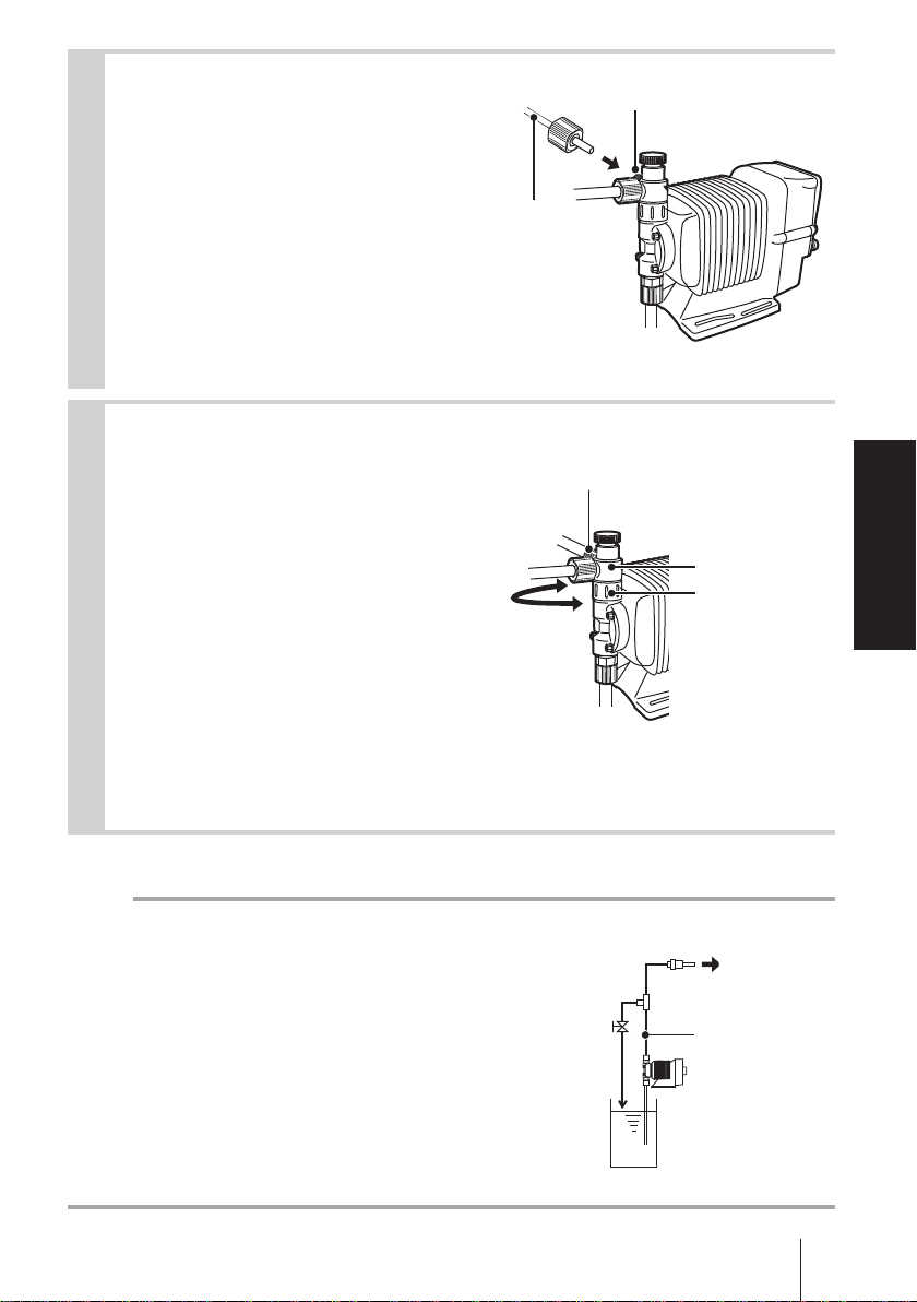
Connect an air bleed tube into the
2
air vent port.
Route back the other tube end to a
supply tank or a container.
For the auto degassing type, con-
nect another air bleed tube into the
automatic air vent valve body as
well.
Determine an air vent port direction.
3
The air vent port can rotate 90 de-
grees.
a. Turn the lock nut anticlockwise.
b. Adjust the direction of the air vent
port.
c. Hand-tighten the lock nut, holding
the air vent body A.
d. Turn the lock nut 90 degrees
clockwise further with an adjustable
wrench or spanner.
Tube
Air vent port
Air vent port
Installation
Air vent body A
Lock nut
NOTE
The air vent port is not provided to the EWN-
FC type. Purchase and install an air vent valve.
Air vent
valve
Check valve
Three way joint
Discharge line
Pump
Pipework
27

Check valve mounting
Install an optional check valve to the EWN (or a back pressure valve to the FC
type) for the prevention of a back ow, siphon and overfeeding.
In the following cases be sure to install the check valve.
• A suction side liquid level is higher than a discharge side (See the diagram
below). Or an injection point is below a suction side liquid level at atmospher-
ic pressure.
Suction side
Discharge side
• The elevation difference between two liquid levels is ve meters or below,
even if a discharge side liquid level is higher than a suction side.
5m or below
Discharge side
Suction side
• A suction side pressure is higher than a discharge side pressure.
• A discharge pressure (including pipe resistance and discharge head) is below
0.13MPa. (0.049MPa for B31 and C36).
28
Pipework
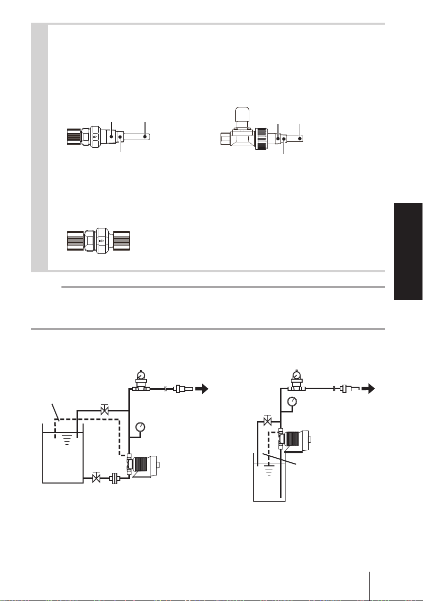
Mount a check valve at the discharge tube end.
1
* The CAN/CBN check valve and the BVC back pressure valve have R1/2 and
R3/8 thread connections as well as a tube connection. Cut off and adjust the
connection length to t the check valves into tubing.
CAN check valve BVC back pressure valve
Outer dia Ф9R1/2
R3/8
* The CBN check valve of which the both ends are tube connections is also
available. Contact us or your nearest distributor.
CBN check valve
Outer dia Ф12R1/2
R3/8
NOTE
Periodically clean or replace a check valve with new one for the prevention of crystal
clogging.
Tubing layout
Flooded suction application Suction lift application
Accumulator/Chamber
Air vent line
Accumulator/Chamber
Check valveCheck valve
Installation
Pump
Pump
* Flooded suction is recommended when handling a gaseous liquid such as sodium
hypochlorite. For the auto degassing type, keep a suction lift at 1m or below. Other-
wise, the air vent valve may not function. Before resuming operation, always perform
degassing by using the adjusting screw.
Air vent line
Pipework
29
Wiring
Wiring for a power voltage and an external signal.
Observe the following points during wiring work.
• Electrical work should be performed by a qualied operator. Always ob-
serve applicable codes or regulations.
• Observe the rated voltage range, or the electrical circuit in the control
unit may fail.
• Do not perform wiring work while electric power is on. Otherwise, an
electrical shock or a short circuit may result. Be sure to turn off the power
before wiring work.
• Be careful for electric power not to be turned on during work.
• Replacement of a power cable should be conducted by a manufacturer,
his agency or a skilled person. Otherwise, an accident may result.
Necessary tools
• Adjustable wrench or spanner • Phillips screw driver
• Precision screw driver
Power voltage/Earthing
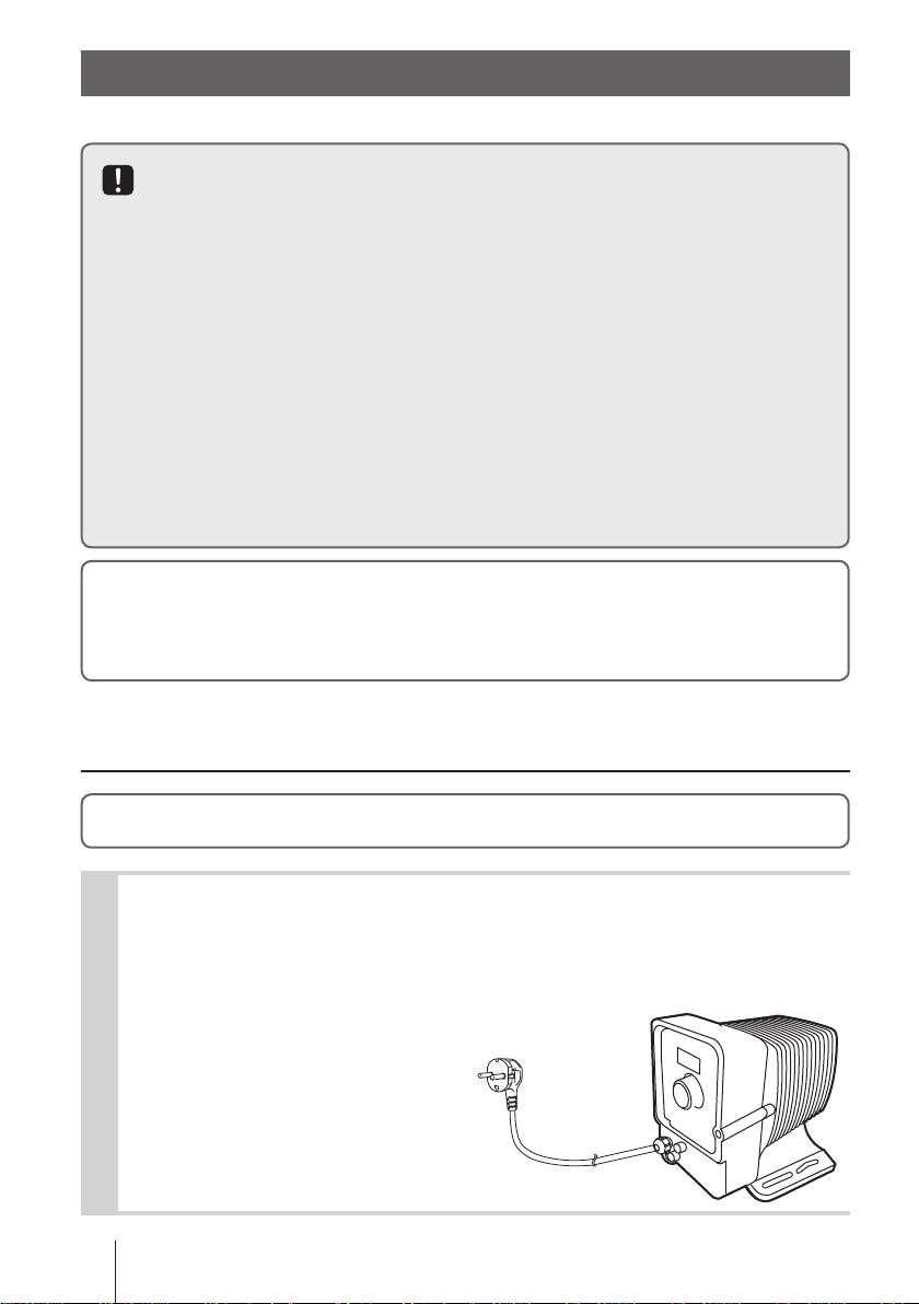
Check that the main power is turned off.
Insert the plug all the way seated in a jack.
1
This product have two power wires and one earth
wire, and is classied as class Ι.
*Make sure the earth plug is seated in securely as well.
30
Wiring
 Loading...