

IWAKI EK Series Instruction Manual

IWAKI PUMPS
EK Series Electronic Metering Pump
Instruction Manual
Five Boynton Road Hopping Brook Park Holliston, MA 01746 USA
TEL: 508-429-1110 WEB: www.walchem.com

Notice
© 2016 WALCHEM, Iwaki America Inc. (hereinafter “Walchem”)
Five Boynton Road, Holliston, MA 01746 USA
tel (508) 429-1110
All Rights Reserved
Printed in USA
Proprietary Material
The information and descriptions contained herein are the property of WALCHEM. Such information and
descriptions may not be copied or reproduced by any means, or disseminated or distributed without the express
prior written permission of WALCHEM.
This document is for information purposes only and is subject to change without notice.
Statement of Limited Warranty
WALCHEM warrants equipment of its manufacture and bearing its identication to be free from defects in
workmanship and material for a period of two years from date of delivery from the factory or authorized
distributor under normal use and service and otherwise when such equipment is used in accordance with
instructions furnished by WALCHEM and for the purposes disclosed in writing at the time purchased, if any.
WALCHEM’s liability under this warranty shall be limited to replacement or repair, F.O.B. Holliston, MA
U.S.A. of any defective equipment or part which, having been returned to WALCHEM, transportation charges
prepaid, has been inspected and determined by WALCHEM to be defective.
THIS WARRANTY IS IN LIEU OF ANY OTHER WARRANTY, EITHER EXPRESS OR IMPLIED, AS TO
DESCRIPTION, QUALITY, MERCHANT-ABILITY, FITNESS FOR ANY PARTICULAR PURPOSE OR
USE, OR ANY OTHER MATTER.
P/N E00269.C
April 2016

Thank you for choosing a Walchem E-Class metering pump. This instruction manual deals with the correct installation,
operation, maintenance and troubleshooting procedures for the EK model metering pumps. Please read through it carefully to ensure the optimum performance, safety and service of your pump.
Contents
1.0 INTRODUCTION ..........................................................................................1
1.1 Safety and Caution Notes ...................................................................................................................... 1
1.2 Principle of Operation ............................................................................................................................ 1
1.3 Model Code ............................................................................................................................................. 2
1.4 Specications ......................................................................................................................................... 2
1.4.1 Electrical ................................................................................................................................ ...... 2
1.4.2 Operating Conditions .................................................................................................................. 2
1.4.3 Capacity/Pressure Rating ............................................................................................................ 3
1.4.4 Adjustment Range ....................................................................................................................... 3
1.4.5 Materials of Construction
1.5 Dimensions ................................................................................................................................... 4
2.0 INSTALLATION ............................................................................................ 6
2.1 Unpacking ............................................................................................................................................... 6
2.2 Location .................................................................................................................................................. 6
2.3 Supply Tubing ......................................................................................................................................... 7
2.4 Discharge Tubing ................................................................................................................................... 8
2.5 Installing Injection/BackPressure Valve ............................................................................................... 8
2.6 Interlocking Pump .................................................................................................................................. 9
2.7 Electrical ................................................................................................................................................. 9
3.0 OPERATION ............................................................................................... 10
3.1 Pump Operation & Programming ....................................................................................................... 10
3.1.1 Programming .............................................................................................................................. 11
3.1.2 Pump Operation ......................................................................................................................... 11
3.2 External Inputs & Outputs ................................................................................................................... 11
3.3 Adjustment ............................................................................................................................................ 12
3.4 MultiFunction Valve Operation ............................................................................................................ 13
3.5 Auto Degassing Valve Operation ........................................................................................................ 14
3.6 Priming .................................................................................................................................................. 14
3.7 Calibration ............................................................................................................................................. 14
3.8 AC Power Interruption ........................................................................................................................ 14
4.0 MAINTENANCE .........................................................................................15
4.1 Diaphragm Replacement ..................................................................................................................... 15
4.2 Valve Replacement ............................................................................................................................... 15
5.0 EXPLODED VIEW & PARTS GUIDE ......................................................... 16
6.0 TROUBLESHOOTING ...............................................................................27
7.0 SERVICE POLICY ...................................................................................... 27
1.0 INTRODUCTION
1.1 Safety and Caution Notes
Always wear protective clothing, eye protection and gloves before working on or near a metering pump.
Follow all recommendations of the supplier of the solution being pumped. Refer to the MSDS from the
solution supplier for additional precautions.
Walchem E-Class metering pumps should be installed where ambient temperatures do not exceed 122°F
(50°C) or do not fall below 32°F (0°C). Pumps should always be shielded from direct exposure to the
elements. Black UV resistant tubing should be used if the tubing is exposed to strong UV radiation (sun-
light/lamps). The EK Series is specically designed to withstand the elements and can be mounted directly
outdoors within the temperature speccations. To protect and maintain the IP rating of the pump, the clear
covers that protect the electronic controls MUST be left in a secured/tightened condition at all times other than
during adjustment of the pump.
WARNING Risk of electrical shock! This pump is supplied with a grounding conductor and grounding-type
attachment plug. To reduce the risk of electrical shock, be certain that it is connected only to a properly
grounded, grounding type receptacle with ratings conforming to the data on the pump data plate. Prior to
performing any maintenance on a pump, disconnect the pump from the electrical power source.
Plumbing Precautions
All tubing must be securely attached to the ttings prior to starting the pump (see Section 2.3). Only use
Walchem tubing with your pump. Tubing should be shielded to prevent possible injury in case of rupture or
damage. UV resistant tubing should be used if the tubing is exposed to UV light. Always adhere to local
plumbing codes and requirements. Be sure that the installation does not constitute a cross connection.
Walchem is not responsible for improper installations. Prior to performing any maintenance on a pump,
depressurize the discharge tubing.
If you are pumping downhill or into little or no system pressure, a back pressure/anti-syphon device must be
installed to prevent over-pumping. Contact your Walchem distributor for additional information.
Solution Compatibility
CAUTION! This pump has been evaluated for use with water only. The suitability of this pump for use with
liquids other than water, such as acid and alkaline, is the responsibility of the user. For liquids other than
water, select the best-suited liquid end material combination using a chemical compatibility chart.
1.2 Principle of Operation
The E-Class electronic metering pumps consist of a pump unit, a drive unit, and a control unit. The drive unit is an
electromagnetic solenoid. When the solenoid coil is energized by the control unit the armature shaft moves forward
due to the magnetic force of the solenoid. The shaft is attached to a PTFE faced diaphragm which is part of the
pump unit. The diaphragm is forced into the pump head cavity decreasing volume and increasing pressure which
forces liquid in the pump head out through the discharge check valves. When the solenoid coil is de-energized, a
spring returns the armature to its starting position. This action pulls the diaphragm out of the head cavity increasing
volume and decreasing pressure. Atmospheric pressure then pushes liquid from the supply tank through the suction
check valves to rell the pump head.
1

1.3 Model Code
EK B16 R 1 - VC A
1 2 3 4 5 6
1 Pump Series
EK IP 67 aggressive environment rated electronic metering pump with external pulse control or
manual speed control (adjustable to 360 strokes per minute) and manually adjustable stroke length.
(Turndown ratio 1800:1.)
2 Capacity/Pressure Rating (See Section 1.4 for detailed chart.)
3 Control Module
R For use on all EK models, features external pulse input control and stop input.
4 Voltage
1 115 VAC, 50/60 Hz
2 230 VAC, 50/60 Hz
5 Liquid End (See Section 1.4 for detailed chart.)
6 Options
A Auto Degassing Valve (ADV) is supplied under the manual air vent valve. Available for
B11/16/21 and C16/21 sizes with -VC/-VE liquid ends only.
M Multifunction Valve is supplied in place of the manual air vent valve. Available on all pumps except
for -FC/-SH liquid ends.
1.4 Specications
1.4.1 Electrical
(50/60 Hz, Single phase)
EKB
EKC
1.4.2 Operating Conditions
Ambient temperature 32°F to 122°F (0°C to 50°C)
Relative humidity 95% (EK) non-condensing
Liquid temperature 32° to 104°F (0 to 40°C) for PVC based liquid ends
115 VAC±10% 0.8 Amp max. 20 watt avg.
230 VAC±10% 0.4 Amp max. 20 watt avg.
115 VAC±10% 1.2 Amp max. 22 watt avg.
230 VAC±10% 0.6 Amp max. 22 watt avg.
32° to 140°F (0 to 60°C) for PP, PVDF, SS based liquid end
Below 32°F (0°C), pump is limited to 70% of max. pressure. Liquid
cannot freeze.
2
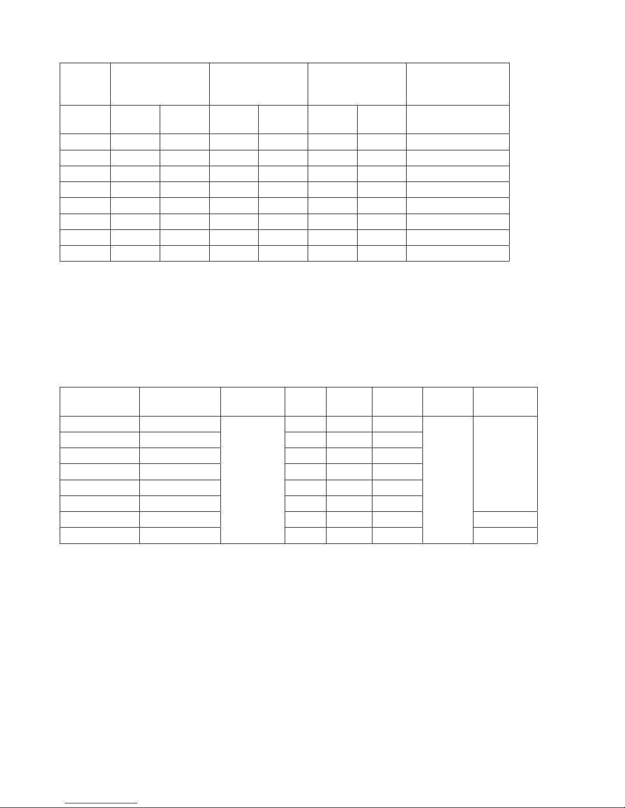
1.4.3 Capacity/Pressure Rating
Connection
Tubing O.D
Size
Maximum
Output Capacity
(Gal/hr)
(mL/
min)
1
Output
per Stroke (mL)
Maximum
Pressure
Min. Max. PSI MPa
B11 0.6 38 0.03 0.11 150 1.0 3/8
B16 1.0 65 0.04 0.18 105 0.7 3/8
B21 1.8 115 0.07 0.32 60 0.4 3/8
B31 3.3 210 0.12 0.58 30 0.2 1/2
C16 1.3 80 0.05 0.22 150 1.0 3/8
C21 2.3 145 0.08 0.40 105 0.7 3/8
C31 4.3 270 0.15 0.75 50 0.35 1/2
2
C36
1
Auto Degassing valve (ADV) reduces output capacity by approximately 20% of rated.
2
Output of the EW/EKC36-TC/FC/SH is 6.3 GPH (400 ml/min)
6.7 420 0.24 1.17 30 0.2 1/2
1.4.4 Adjustment Range
Stroke length adjustment range
Frequency adjustment range
20% to 100%
0 to 360 strokes per minute
1.4.5 Materials of Construction
Liquid End
Code
PC GFRPP
PE GFRPP CE EPDM EPDM
VC PVC CE FKM FKM
VE PVC CE EPDM EPDM
VF PVC PTFE EPDM EPDM
TC PVDF CE FKM FKM
FC PVDF CE PCTFE PTFE
SH (N) 316 SS HC 316SS PTFE ¼” NPTF
CE Alumina ceramic PVC Polyvinylchloride (translucent)
PE Polyethylene GFRPP Glass ber reinforced polypropylene
EPDM Ethylene propylene diene monomer PVDF Polyvinylideneuoride
PTFE Polytetrauoroethylene HC Hastelloy C276
FKM Fluoroelastomer SS 316 stainless steel
PCTFE Polychlorotriuoroethylene
Pump Head
& Fittings
Diaphragm
PTFE
(bonded to
EPDM)
Valve
Balls
Valve
Seat
Valve
Seals
CE FKM FKM
Gasket Tubing
Size (in)
PE
PTFE
3
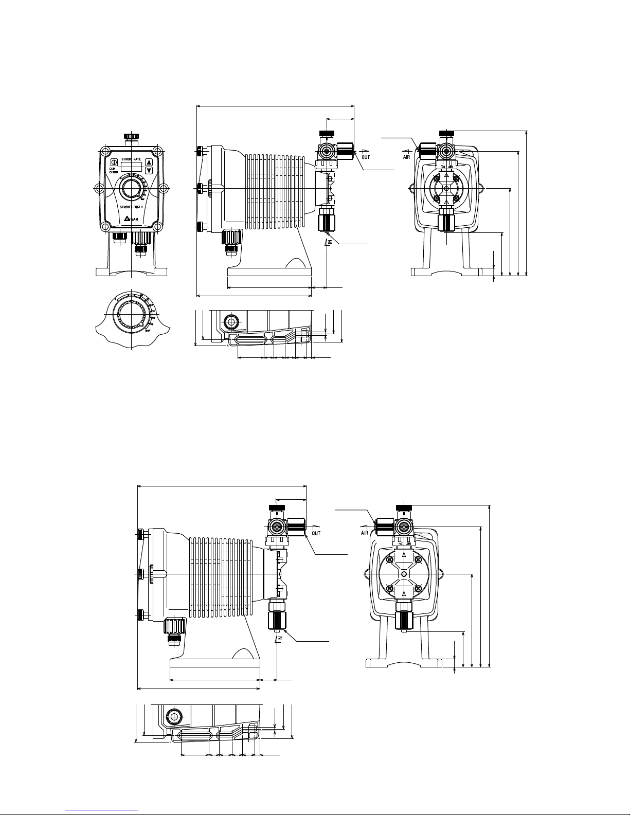
1.5 Dimensions
(All dimensions in inches)
EK-11,16 and 21 Models with thermoplastic liquid end materials
10.65” (see note 1)
1.85”
ø1/4” x ø3/8”
ø1/4” x ø3/8”
ø1/4” x ø3/8”
0.51”
2.91”
5.91”
9.8” (see note 3)
8.43” (see note 2)
7.78”
1.02”5.71”
3.15”
4.33”
4.80”
3.94”
1.77”
0.67”
0.79”
0.67” 0.79”
0.24”
0.31”
Notes:
1. Addition of a Multifunction valve increases overall length by 0.10".
2. Addition of a Multifunction Valve increases discharge height by 2.62". The Auto Degassing Valve increases discharge height by 1.82".
3. Addition of a Multifunction Valve increases overall liquid end height by 1.25". The Auto Degassing Valve increases height by 1.82"
EK-31 and 36 Models with thermoplastic liquid ends
10.73” (see note 1)
1.85”
ø1/4” x ø3/8”
ø1/4” x ø3/8”
7.78”
3.94”
4.80”
1.77”
0.79”
0.67”
10.28” (see note 3)
8.96” (see note 2)
5.91”
ø1/4” x ø3/8”
0.51”
2.24”
1.08”5.71”
4.33”
3.15”
0.24”
0.79”0.67”
0.31”
4
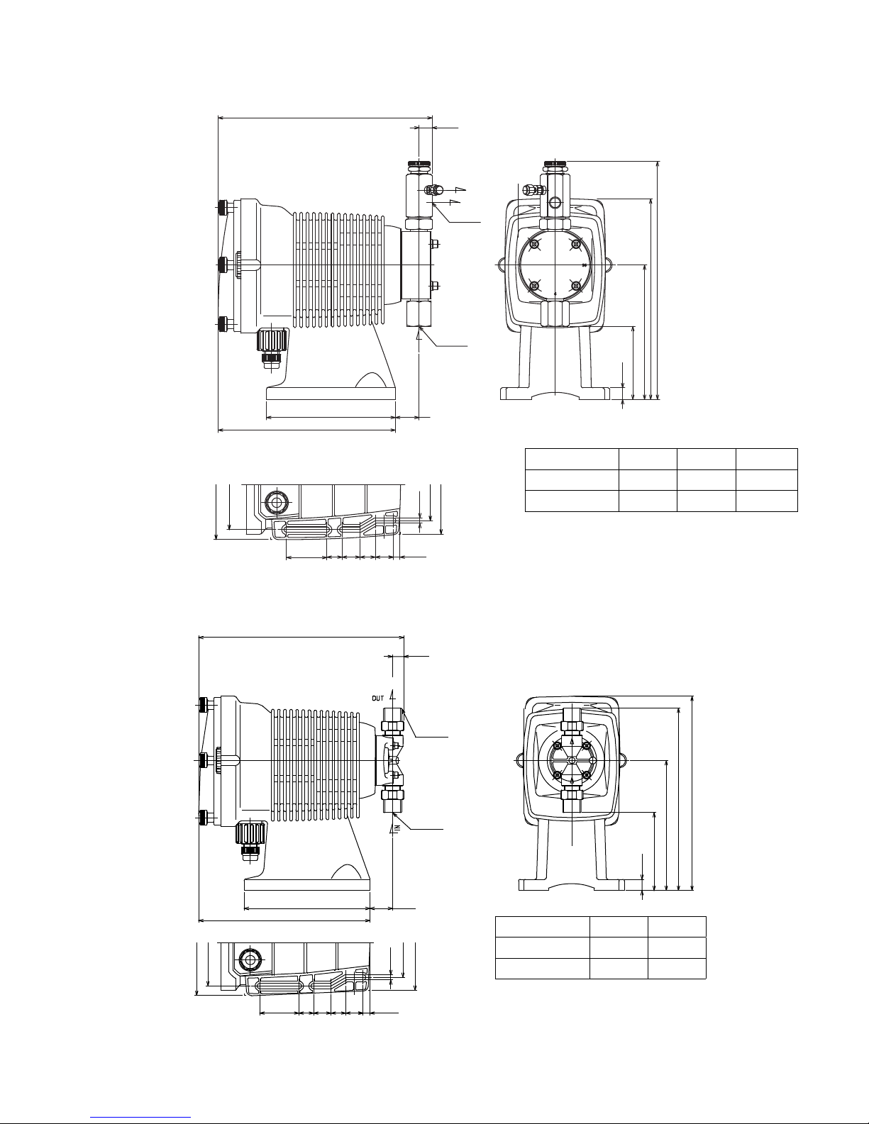
EK Models with SH liquid end
9.39”
0.57”
AIR
OUT
1/4” NPT
Y
4.80”
3.94”
7.78”
1.77”
9.31”
1/4” NPT
IN
5.66”
0.67” 0.79”
0.67” 0.79”
0.29”
0.24”
1.04”
3.15”
4.33”
EK Models with FC liquid end
0.51”
36
6
Z
5.91”
X
0.51”
Model Size X Y Z
11,16, 21 3.70" 8.07" 9.88"
31, 36 3.31" 8.54" 10.37"
7.78”
3.94”
4.80”
1.77”
5.71” 1.02”
3.15”
0.24”
0.67” 0.79”
0.67” 0.79”
0.31”
1/4” NPT
1/4” NPT
4.33”
Y
8.82”
5.91”
X
0.51”
Model Size X Y
11,16, 21 3.54" 8.28"
31, 36 2.88" 8.88"
5
2.0 INSTALLATION
2.1 Unpacking
Open the shipping carton and inspect contents for damage. If any items are missing or damaged contact your local
distributor.
Pumps are pre-primed with water at the factory. If the application is not compatible with water, drain and
dry before use. Be sure to remove caps from ttings before attaching tubing.
CAUTION: Head bolts may have loosened during storage or shipment. Be sure to check and tighten to
19 lb-in torque, if necessary.
2.2 Location
Choose a location for the pump which is clean, dry, vibration-free, close to an electrical outlet, and allows convenient
access to stroke length control, frequency control, and tubing connections. Avoid areas where ambient temperature
exceeds 122°F (50°C) or falls below 32°F (0°C). Pumps should always be shielded from direct exposure to the elements.
Black UV resistant tubing should be used if the tubing is exposed to strong UV radiation (sunlight/lamps).
The EK Series is specically designed to withstand the elements and can be mounted directly outdoors within the
temperature specications.
This pump is cord connected and not intended for permanent mounting to a building structure. However, temporary
mounting to stabilize the pump during operation may be necessary as long as tools are not required for the installation
or removal of the pump.
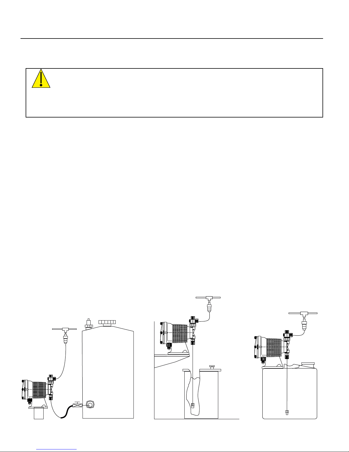
Flooded suction (mounting the pump below the level of liquid in the supply tank) is strongly recommended, especially
when pumping liquids that readily generate gas bubbles. Sodium hypochlorite and hydrogen peroxide are common
examples of such liquids. (See Figure 1.)
If ooded suction mounting is not possible, a shelf adjacent to (but not directly above) the supply tank often works
well. (See Figure 2.) The supply tank or cover can also be used if it has provisions for mounting a pump. (See Figure
3.) In any case, the total suction lift should not exceed 5 ft (1.5m).
Figure 1 Flooded suction
Recommended for liquids
that out-gas
Figure 2 Shelf mount Figure 3 Tank mount
6
 Loading...