

IWAKI EHN-YN Instruction Manual

Iwaki
Electromagnetic Metering Pump
EHN-YN
Safety instructions Overview Installation Operation Maintenance Specifications
Instruction manual
Thank you for choosing our product.
Please read through this instruction manual before use.
This instruction manual describes important precautions and instructions for the product. Always keep it on hand for quick reference.
©2010 IWAKI CO., LTD.
Order confirmation
Open the package and check that the product conforms to your order. If any problem or
inconsistency is found, immediately contact your distributor.
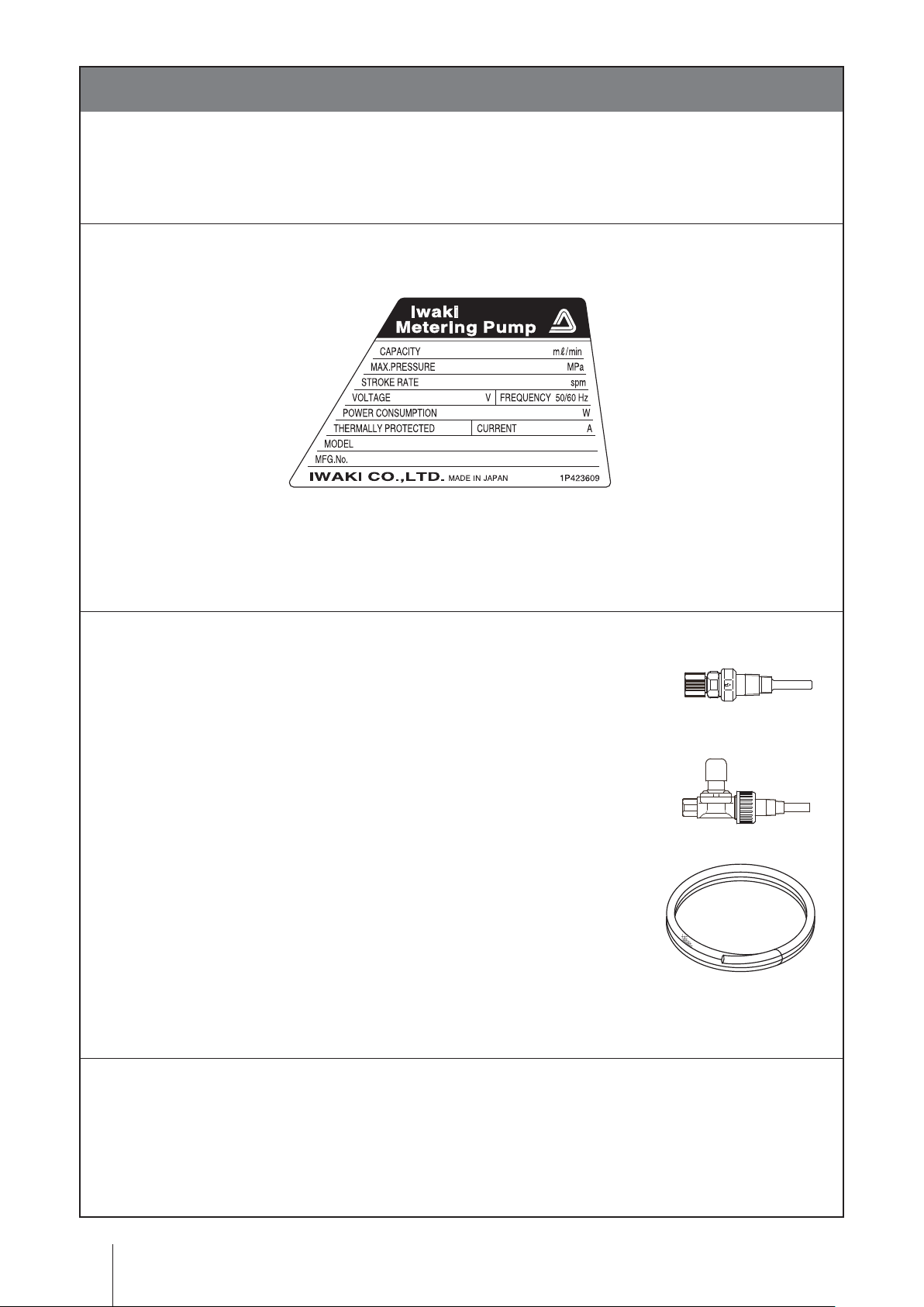
a. Check if the delivery is correct.
Check the nameplate to see if the information such as model codes, discharge capacity, discharge pressure
and power voltage are as ordered.
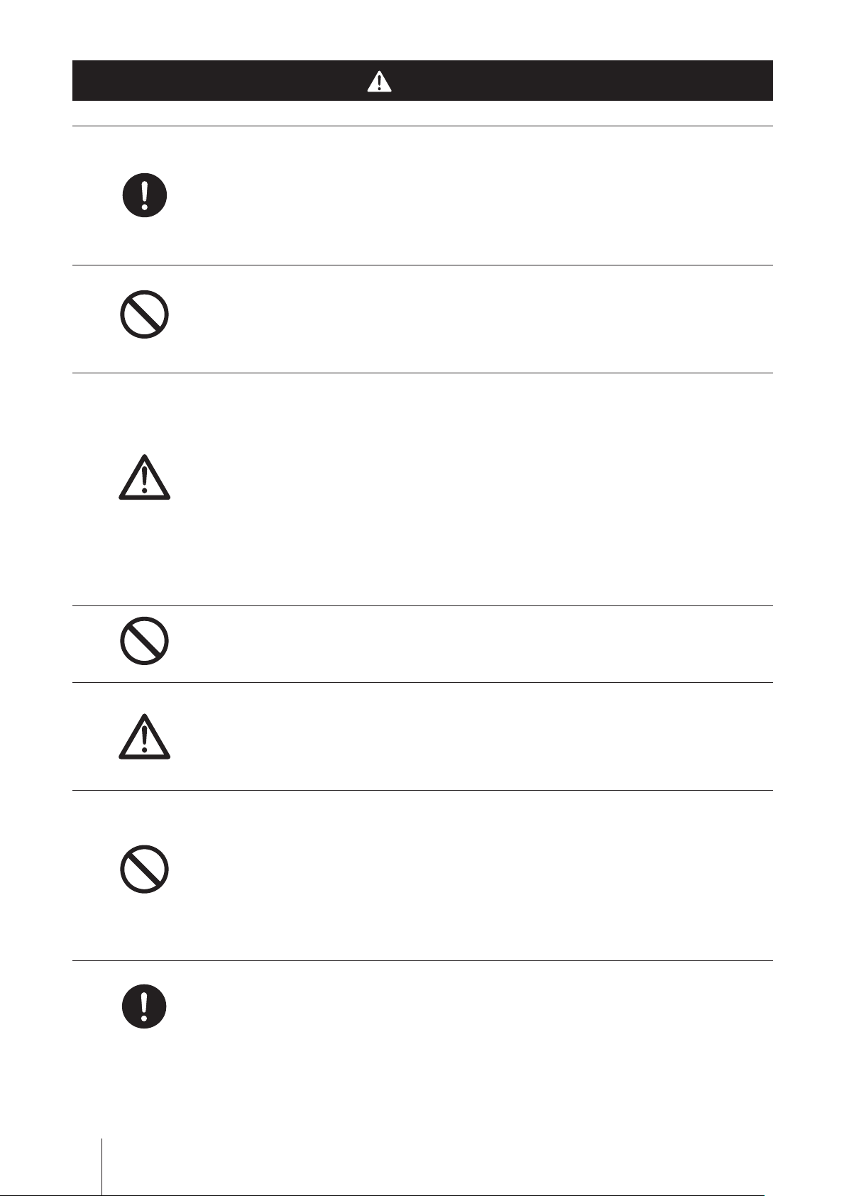
b. Check accessories are complete.
• A check valve or a back pressure valve
* The attached check valve and back pressure valve vary with pump models. See page 73
for accessory list.
• A 3m PVC braided tube (ø4×ø9 or ø8×ø13)
* ø4×ø9 or ø8×ø13 EVA tube is attached to the PP type.
*No tube is attached to all the FC and SH types.
c. Check if the delivery is damaged or deformed.
Check valve
Back pressure valve
Check for transit damage and loose bolts.
Order confirmation
2

Contents
Order confirmation ..........................................................................................................................................2
Safety instructions .................................................................... 6
Warnings ........................................................................................................................................................ 7
Cautions ......................................................................................................................................................... 8
Precautions for use .................................................................................................................................... 10
Overview ...................................................................................12
Introduc tion ................................................................................................................................................. 12
Pump structure & Operating principle ...................................................................................................... 12
Features ...................................................................................................................................................13
Operational function ................................................................................................................................... 13
Manual mode ........................................................................................................................................... 13
EXT mode ................................................................................................................................................ 14
Proportional control ............................................................................................................................. 14
Multiplier programming ....................................................................................................................... 14
Divisor programming ........................................................................................................................... 15
STOP function .....................................................................................................................................15
Priming function ..................................................................................................................................16
Auto restoration ...................................................................................................................................16
Part names ................................................................................................................................................... 17
Pump ........................................................................................................................................................ 17
Operation panel ........................................................................................................................................ 18
Basic displays .....................................................................................................................................19
Alarm displays .....................................................................................................................................20
Other displays .....................................................................................................................................20
Auto restoration displays (FCM type) ..................................................................................................21
Identification codes ....................................................................................................................................22
Pump ........................................................................................................................................................22
Control unit ...............................................................................................................................................23
Installation .............................................................................. 24
Pump mounting ...........................................................................................................................................24
Plumbing ......................................................................................................................................................25
Tube connection .......................................................................................................................................25
VC/VH/PC/PH/PP/FC/SH types .......................................................................................................... 25
SH type ...............................................................................................................................................26
Check valve mounting ..............................................................................................................................27
Wiring ...........................................................................................................................................................29
Power voltage/Earthing ............................................................................................................................ 29
Signal wire connection .............................................................................................................................30
Contents
3

Operation ................................................................................. 33
Before operation .........................................................................................................................................33
Points to be checked ................................................................................................................................33
Retightening of pump head fixing bolts .................................................................................................... 33
Use of a hexagon wrench instead of a torque wrench ........................................................................ 33
Degassing ................................................................................................................................................34
EHN-B/-C 11/16/21 VC/VH/PC/PH/PP/SH .........................................................................................34
EHN-B/-C 11/21 FC and EHN-B/-C 31/36 VC/VH/PC/PH/PP/FC ......................................................36
Flow rate adjustment ................................................................................................................................ 37
Flow rate, stroke rate and stroke length .............................................................................................. 37
Precautions of flow rate adjustment ....................................................................................................37
Stroke rate adjustment ........................................................................................................................38
Stroke length adjustment ....................................................................................................................39
Before a long period of stoppage (One month or more) ..........................................................................39
Operation programming ............................................................................................................................. 40
Programming flow .................................................................................................................................... 41
Operation .....................................................................................................................................................42
Manual operation .....................................................................................................................................42
EXT operation .......................................................................................................................................... 42
Analog control programming ...............................................................................................................42
Digital control programming ................................................................................................................ 44
STOP function ..........................................................................................................................................48
Keypad lock .............................................................................................................................................. 49
Keypad lock activation ........................................................................................................................49
Keypad lock release ............................................................................................................................ 49
Priming function .......................................................................................................................................49
Auto restoration (FCM type) .....................................................................................................................50
Auto restoration programming ............................................................................................................50
Auto restoration (FCM type) .....................................................................................................................53
Reset of "PErr" (Full speed operation to resolve air lock) ...................................................................53
Reset of "FLOW" (Suspended operation after failing to resolve air lock) ...........................................53
Maintenance ............................................................................ 54
Troublesho oting ..........................................................................................................................................54
Pump ...................................................................................................................................................54
Inspection ....................................................................................................................................................56
Daily inspection ........................................................................................................................................56
Periodic inspection ...................................................................................................................................56
Wear part replacement ............................................................................................................................... 57
Wear part list ............................................................................................................................................ 57
Before replacement ..................................................................................................................................58
Contents
4

Discharge valve set disassembly/assembly ........................................................................................ 58
Suction valve set disassembly/assembly ............................................................................................60
Air vent valve set replacement (SH type) ................................................................................................. 61
Air vent valve set replacement (NAE type)...............................................................................................62
Flow checker replacement (FCM/XFCM) .................................................................................................62
Diaphragm replacement ...........................................................................................................................64
Exploded view .............................................................................................................................................66
Pump head, Drive unit & Control unit .......................................................................................................66
Pump head ...............................................................................................................................................67
EHN-B11/-B16/-B21/-C16/-C21 VC/VH/PC/PH .................................................................................. 67
EHN-B31/-C31/-C36 VC/VH/PC/PH ...................................................................................................67
EHN-B11/-B16/-B21/-B31/-C16/-C21/-C31/-C36 PP ...........................................................................68
EHN-B11/-B16/-B21/-B31/-C16/-C21/-C31/-C36 FC ...........................................................................68
EHN-B11/-B16/-B21/-B31/-C16/-C21/-C31/-C36 SH ........................................................................... 69
EHN-B11/-B16/-B21/-B31/-C16/-C21/-C31/-C36 -NAE .......................................................................69
EHNB-11/-B16/-B21/-B31/-C16/-C21/-C31/-C36 -FCM/-XFCM ..........................................................70
Check valve (VC/VH/PC/PH) ................................................................................................................... 70
Specifications/Outer dimensions .............................................................................................................. 71
Specifications ........................................................................................................................................... 71
Pump ................................................................................................................................................... 71
Control unit ..........................................................................................................................................72
Power cable ........................................................................................................................................72
Pump colour ........................................................................................................................................ 72
Accessories ......................................................................................................................................... 73
Options ................................................................................................................................................73
Outer dimensions ..................................................................................................................................... 74
EHN-B11/-B16/-B21 VC/VH/PC/PH/PP .............................................................................................. 74
EHN-B31 VC/VH/PC/PH/PP ............................................................................................................... 74
EHN-C16/-C21 VC/VH/PC/PH/PP ...................................................................................................... 75
EHN-C31/-C36 VC/VH/PC/PH/PP ...................................................................................................... 75
EHN-B11/-B21 FC ............................................................................................................................... 76
EHN-C21 FC ....................................................................................................................................... 76
EHN-C31/-C36 FC ..............................................................................................................................77
EHN-B11/-B21 SH ...............................................................................................................................78
EHN-C21 SH ....................................................................................................................................... 78
EHN-C31 SH .......................................................................................................................................79
EHN-C36 SH ......................................................................................................................................79
EHN- B11/-B16-N AE ............................................................................................................................80
EHN-C16/-C21-NAE ...........................................................................................................................80
EHN- B11/-B16-/B21-FCM/-XFCM ....................................................................................................... 81
EHN-C16/-C21-FCM/-XFCM ..............................................................................................................81
Contents
5

Safety instructions
Read through this section before use. This section describes important
information for you to prevent personal injury or property damage.
■
Symbols
In this instruction manual, the degree of risk caused by incorrect use noted with the following
symbols. Please pay attention to the information associated with the symbols.
Indicates mishandling could lead to a fatal or serious
WARNING
CAUTION
A symbol accompanies each precaution, suggesting the use of "Caution", "Prohibited actions"
and specific "Requirement".
accident.
Indicates mishandling could lead to personal injury or prop-
erty damage.
Caution marks Prohibition mark Requirement mark
Caution
Electrical
shock
Prohibited
Do not rework
or alter
Requirement
Wear
protection
Grounding
Export restrictions
Technical information contained in this instruction manual might be treated as controlled tech-
nology in your countries, due to agreements in international regime for export control.
Please be reminded that export license/permission could be required when this manual is
provided, due to export control regulations of your country.
Safety instructions
6

Electrical
shock
Requirement
Safety instructions
WARNINGS
Turn off power before service
Risk of electrical shock. Be sure to turn off power to stop the pump and
related devices before service is performed.
Stop operation
If you notice any abnormal or dangerous conditions, suspend operation
immediately and inspect/solve problems.
Do not use the pump in any condition other than its intended purpose
The use of the pump in any conditions other than those clearly specified
Prohibited
Do not remodel
Wear
protectors
Prohibited
may result in failure or injury. Use this product in specified conditions only.
Do not modify the pump
Alterations to the pump carries a high degree of risk. It is not the manufactur-
er's responsibility for any failure or injury resulting from alterations to the pump.
Wear protective clothing
Always wear protective clothing such as an eye protection, chemical re-
sistant gloves, a mask and a face shield during disassembly, assembly or
maintenance work. The specific solution will dictate the degree of protec-
tion. Refer to MSDS precautions from the solution supplier.
Do not damage the power cable
Do not pull, knot or crush the power cable. Damage to the power cable
could lead to a fire or electrical shock if cut or broken.
Do not operate the pump in a flammable atmosphere
Prohibited
Do not place explosive or flammable material near the pump.
WARNINGS
7
Requirement
CAUTIONS
Qualified personnel only
The pump should be handled or operated by qualified personnel with a
full understanding of the pump. Any person not familiar with the product
should not take part in the operation or management of the pump.
Use specified power only
Do not apply power other than that specified on the nameplate. Otherwise,
Prohibited
Caution
Prohibited
failure or fire may result. Ensure the pump is properly grounded.
Do not run pump dry
Do not run pump dry for more than 30 minutes (even when the pump runs
for degassing). Otherwise, the pump head fixing screws may loosen and
liquid may leak. Optimise your system in order for the pump not to run
dry. If the pump runs dry for a long period (for more than 30 minutes), the
pump head and the valve cases may deform by friction heat and conse-
quently leakage results.
Keep electric parts and wiring dry
Risk of fire or electric shock. Install the pump where it can be kept dry.
Ventilation
Fumes or vapours can be hazardous with certain solutions. Ensure proper
Requirement
CAUTIONS
8
Caution
Prohibited
ventilation at the operation site.
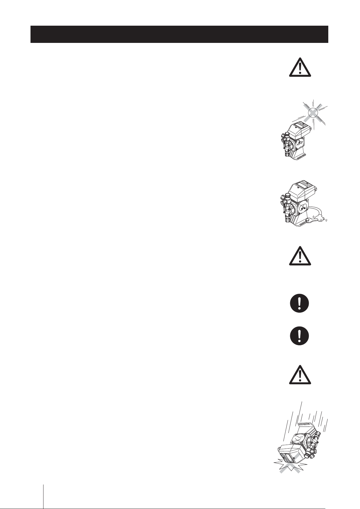
Do not install/store the pump:
• In a flammable atmosphere.
• in a dusty/humid environment.
• Where ambient temperature can exceed 0-40ºC.
• In direct sunlight or wind & rain.
Spill precautions
Ensure protection and containment of solution in the event of plumbing or
pump damage (secondary containment).
Do not use the pump in a wet location
The pump is not waterproof. Use of the pump in wet or extremely humid
Safety instructions
Prohibited
Grounding
Electrical
shock
Requirement
Prohibited
locations could lead to electric shock or short circuit.
Grounding
Risk of electrical shock! Always properly ground the pump. Conform to lo-
cal electric codes.
Install a GFCI (earth leakage breaker)
An electrical failure of the pump may adversely affect other devices on the
same line. Purchase and install an earth leakage breaker separately.
Preventative maintenance
Follow instructions in this manual for replacement of wear parts. Do not
disassemble the pump beyond the extent of the instructions.
Do not use a damaged pump
Using a damaged pump could lead to an electric leak or shock.
Requirement
Caution
Requirement
Disposal of a used pump
Dispose of any used or damaged pump in accordance with local rules
and regulations. If necessary, consult a licensed industrial waste disposal
company.
Check the pump head bolts
Liquid may leak if any of pump head bolts become loose. Tighten the bolts
evenly to the specified torque below in diagonal order before initial opera-
tion and at regular intervals.
Tightening torque
EHN-B11/-B16/-B21/-C16/-C21 : 2.16 N•m
EHN-B31/-C31/-C36 : 2.55 N•m
Install a relief valve
Install a relief valve on a discharge line near the pump so as to automati-
cally release the discharge pressure when it exceeds the maximum level.
CAUTIONS
9
Precautions for use
• Electrical work should be performed by a qualified electrician. Otherwise,
personal injury or property damage may result.
• Do not install the pump:
–In a flammable atmosphere.
–In a dusty/humid place.
–In direct sunlight or wind & rain.
–Where ambient temperature can exceed 40ºC or falls below 0ºC.
Protect the pump with a cover when installing it out of doors.
• Select a level location, free from vibration, that won't hold liquid. Anchor
the pump with four M5 bolts so it doesn't vibrate. If the pump is installed
level, output may be affected.
• When two or more pumps are installed together, vibration may be signifi-
Caution
cant, resulting in poor performance or failure. Select a solid foundation
(concrete) and fasten anchor bolts securely to prevent vibration during
operation.
• Allow sufficient space around the pump for easy access and maintenance.
• Install the pump as close to the supply tank as possible.
• When handling liquids that generate gas bubbles (sodium hypochlorite or
hydrazine solution), install the pump in a cool and dark place. Flooded suc-
tion installation is strongly recommended.
• Use care handling the pump. Do not drop. An impact may affect pump
performance. Do not use a pump that has been damaged to avoid the risk
Caution
Requirement
Requirement
Caution
of electrical damage or shock.
Precautions for use
10
• The pump has a rating of IP65, but is not waterproof. Do not operate the
pump while wet with solution or water. Failure or injury may result. Immedi-
ately dry off the pump if it gets wet.
• Do not close discharge line during operation. Solution may leak or tub-
ing may break. Install a relief valve to ensure safety and prevent damaged
plumbing.
• Do not remove the control unit. Note that an applicable control unit differs
with each drive unit. Do not attach a control unit to a different drive unit.
Otherwise, an electrical circuit or the drive unit may fail.
Safety instructions
Caution
Caution
Caution
• Solution in the discharge line may be under pressure. Release the pres-
sure from the discharge line before disconnecting plumbing or disassembly
of the pump to avoid solution spray.
• Wear protective clothing when handling or working with pumps. Consult
solution MSDS for appropriate precautions. Do not come into contact with
residual solution.
• Do not clean the pump or nameplate with a solvent such as benzine and
thinner. This may discolour the pump or erase printing. Use a dry or a
damp cloth or a neutral detergent.
Requirement
Caution
Thinner
Benzine
Precautions for use
11
Overview
Pump characteristics, features and part names are described in this section.
Introduction
Pump structure & Operating principle
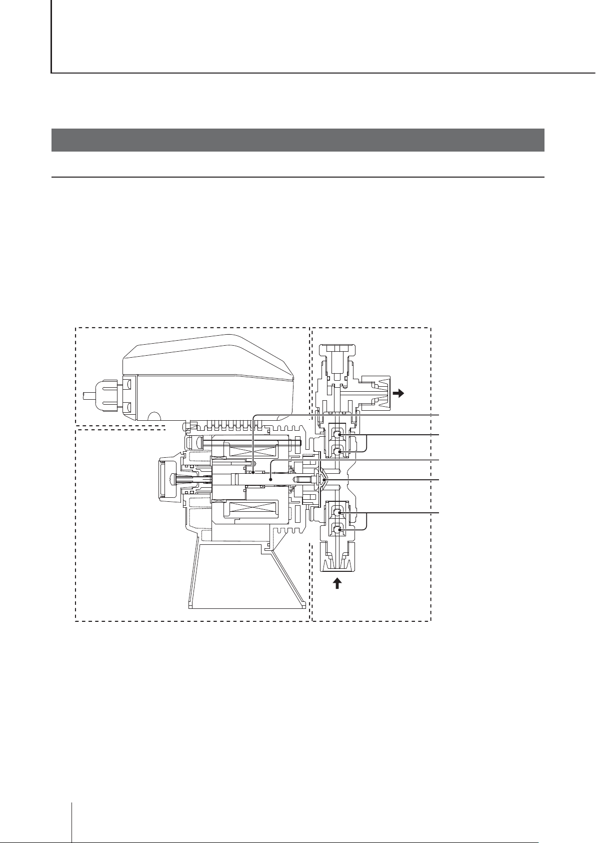
The EHN series is a diaphragm metering pump which consists of a pump head, drive unit and control unit. A
diaphragm is directly driven by electromagnetic force.
Principle of operation
Electromagnetic force and spring force make reciprocating motion. The reciprocating motion is transferred to a
diaphragm through a plunger and then volumetric change occurs in the pump head. This action transfers liquid
along with pump head valve action.
Control unit Pump head
Stroke length
adjusting knob
OUT
Spring
Pump head valve
(Discharge side)
Plunger
Diaphragm
Pump head valve
(Suction side)
IN
Drive unit
12
Introduction

Features
● Multivoltage operation
The EHN series is a multivoltage type (100-240VAC) and can be selected without concern for local power
voltage.
● High turndown ratio
Offers a digitally-controlled range of 1-360 (1spm resolution).
● IP rating of 66
The sealed drive unit and control unit assure IP66.
* This pump is not water resistant. Protect the pump with a cover when installing it out of doors.
● External control
External signals through an analogue and a digital input can control operation. Use the analogue input to
make proportional control and the digital input to run the pump with a multiplier or a divisor.
● Auto degassing system (Auto degassing type)
Enables gaseous liquid delivery, expelling gas to open air to prevent gas lock in the pump head.
● Auto restoration (FCM type)
The pump starts to run at a full speed (360spm) once a flow checker detects gas lock in the pump head.
* The pump stops when having failed to resolve gas lock.
* The XFCM type flow checker can not be connected to the EHN-YN. Connect it to an external controller to make feed-
back control.
Overview
Operational function
Manual mode
Run/stop the pump by the start/stop key. A stroke rate (MAN speed) can be changed in the range of 1-360spm
by the up and the down keys at any time during operation or stop. See page 42 for detail.
Key operation
(Push
Pump operation
key)
Run
Stop
Run
Stop
Operational functions
13

EXT mode
■ Proportional control (Analogue control : See page 42)
The pump increases/decreases a stroke rate in the range of 0-360spm in proportion to 0-20mA.
Setting two points can draw a straight line. Depending on the position of the two points, 0spm may not come
at 0mA or a stroke rate may go over 360spm (The maximum stroke rate is 360spm and the pump does not
exceed that rate.).
360spm
P2
Conditions
a. A1 and A2 must be 20mA or below
b. P1 and P2 must be 360spm or below
c. A1 and A2 must be different mA
d. P1 and P2 must be different spm
P1
0
A1
A2 20mA
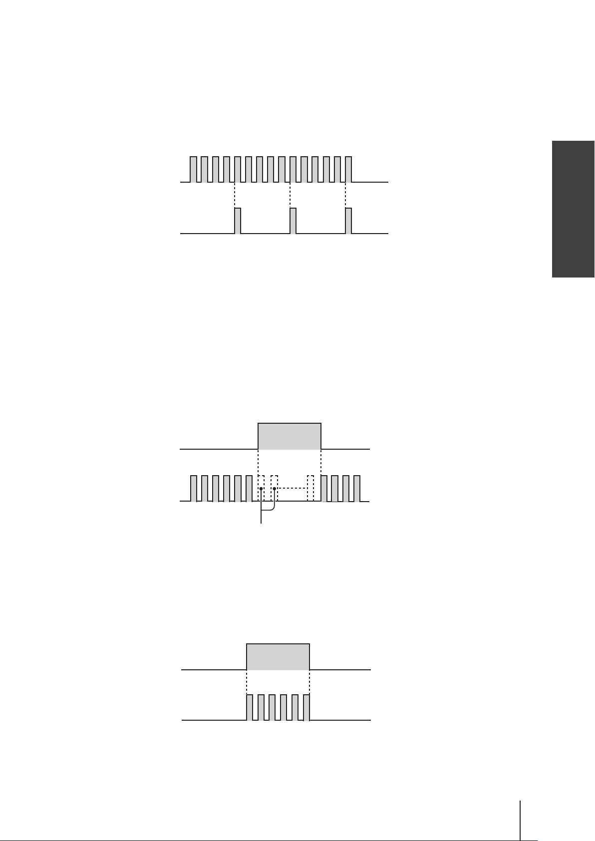
■ Multiplier programming (Digital control : See page 44)
The pump operation by the external signal. Program a multiplier before operation. 1-999 shots can be allocated
to one pulse signal. See page 44 for detail.
*In the EXT operation, the pump runs at a MAN speed.
*The pump makes one shot per pulse when a multiplier is programmed to 1.
Example) When the multiplier is programmed to 5, the pump makes five shots per signal.
Pulse signal input
Pump operation
1 2 3 4 5 1 2 3 4 5
A buffer works when the pump receives an external signal before the programmed shots per signal
is completed.
*The buffer stores up to 255 pulses.
Pulse signal input
Pump operation
1 2 3 4 5 1 2 3 4 5 1 2 3 4 5 1 2 3
14
Operational functions
■ Divisor programming (Digital control : See page 46)
The pump operation by the external signal. Program a divisor before operation. 1-999 pulse signals can be al-
located to make one shot.
* The pump can not run over a MAN speed even if a divisor is set to run the pump beyond that speed.
*The pump makes one shot per pulse when a divisor is programmed to 1.
Example) When a divisor is programmed to 5, the pump makes one shot every 5 signals.
Pulse signal input
1 2 3 4 5 1 2 3 4 5 1 2 3 4 5
Pump operation
■ STOP function (See 48 page)
The start/stop of the pump can be controlled by the external STOP signal.
Operation stop at the STOP signal input: "M-OF"
The pump stops while receiving the STOP signal.
*The pump resumes operation when the stop signal is released.
STOP signal input
Overview
Run Run
Pump operation
Stop
The pump stops running while
the STOP signal is inputted.
Operation resumption at the STOP signal input: "M-ON"
The pump runs while receiving the STOP signal.
*The pump stops operation when the stop signal is released.
STOP signal input
Run
Pump operation
Stop Stop
Operational functions
15
■ Priming function (See page 49)
The pump runs at the maximum stroke rate while both the UP and DOWN keys are pressed. Use this function
for priming or degassing.
Press Press
▲+▼ keys
Pump operation
1 2 3 4 5 1 2 3
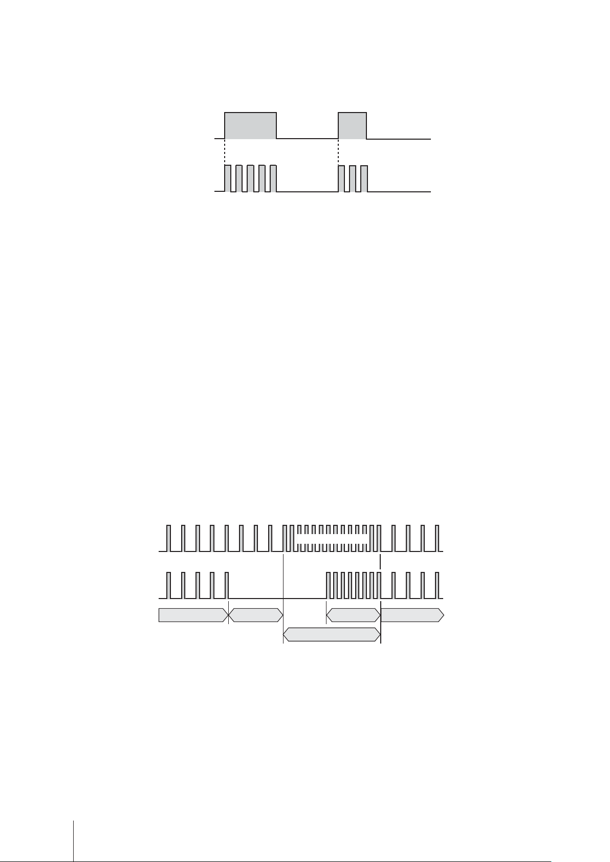
■ Auto restoration (FCM type : See page 50)
The pump starts to run at a full speed (360spm) once a flow checker detects gas lock in the pump head. Pro-
gram the following time periods before operation.
Pre-Alarm time programming
Set a time period from the detection of gas lock to the start of full speed operation. The pump keeps running
along with setting during this period.
Alarm time programming
Set a time period of the full speed operation. The pump stops when having failed to resolve gas lock in this
period.
Return time programming
Set a time period from the resolution of gas lock to the resumption of set operation. The pump keeps running
at the full speed during this period.
Pump operation
Pulse signal input
Normal operation
Pre-Alarm time
Full speed operation
Return time
Alarm time
Nromal operation
Operational functions
16
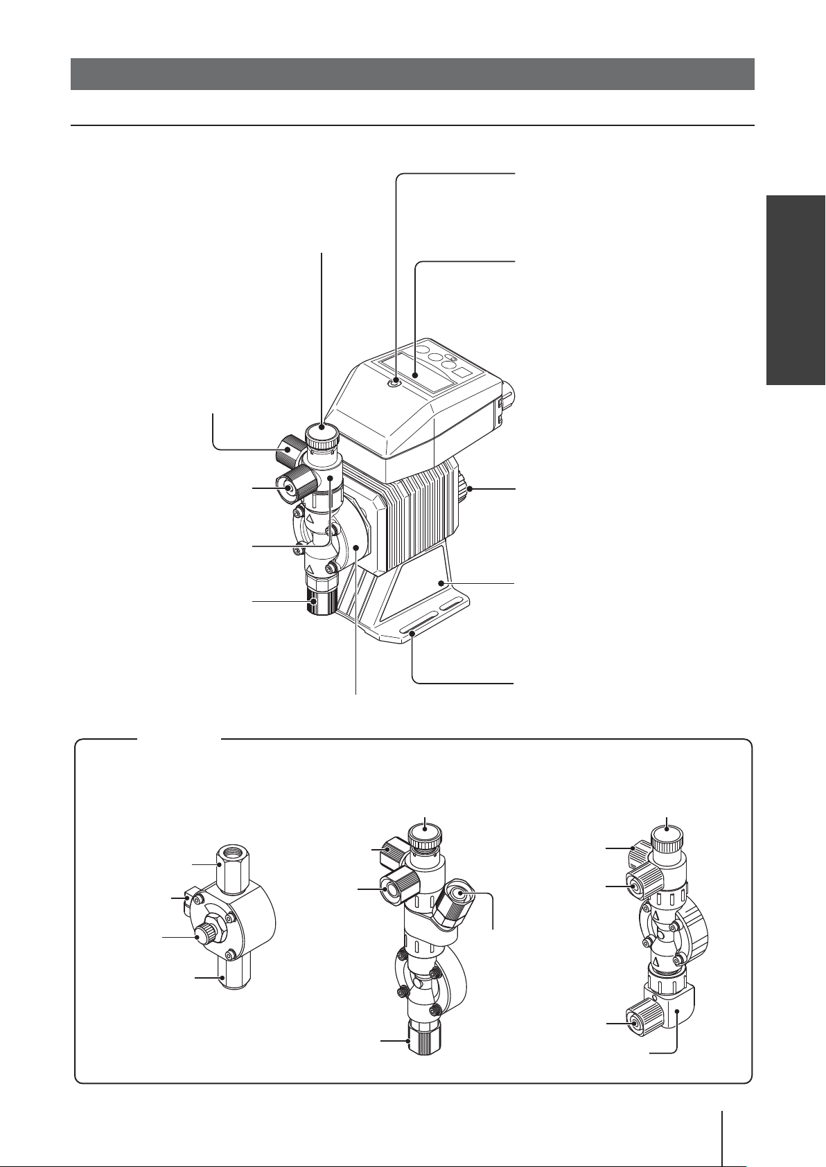
Part names
Pump
Gasket
Covers a control unit mounting
screw.
Adjusting screw
Used for opening the air vent port.
Air vent port
Always connect a tube.
Be sure to return the tube
end to a supply tank or a
container.
The air vent port can
rotate 90 degrees.
Outlet
Air vent body
Inlet
Overview
Control unit
Used for the start/stop of the
pump and stroke rate adjustment/programming.
Stroke length adjusting knob
Used for adjusting a flow rate.
Nameplate
Describes the pump specifications.
Pump heads
Outlet
Air vent port
Adjusting
screw
Inlet
Base
Pump head
SH type AUTO degassing type FCM/XFCM type
Adjusting screw
Air vent port
Outlet
AUTO air
vent por t
Inlet
Always fix with bolts.
Adjusting screw
Air vent port
Outlet
Inlet
Flow checker
Part names
17
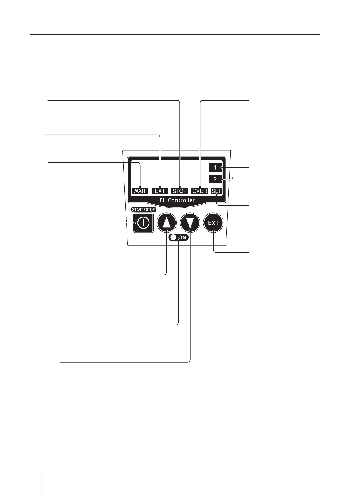
Operation panel
STOP
Lights as the pump stops
running by the STOP signal.
EXT
Lights during EXT operation.
WAIT
Lights during a wait state.
START/STOP key
Used for starting/stopping operation or entering a setting.
OVER
Lights when the pump is set
to run over 360spm through
an EXT mode.
Set point 1 and 2
Lights when set point 1 and
2 are being set for analogue
control.
SET
Appears at the Analogue/
Digital selection mode or
in the EXT mode programming.
EXT key
Used for starting EXT
operation.
UP key
Used for increasing numeric values or scrolling up options.
Push this key while pressing the
EXT key to call up the Analogue/
Digital selection mode.
ON LED
Lights as turning on power and
flashes at each stroke.
DOWN key
Used for decreasing numeric values
or scrolling down options.
Push this key while pressing the
EXT key to program the EXT mode.
18
Part names
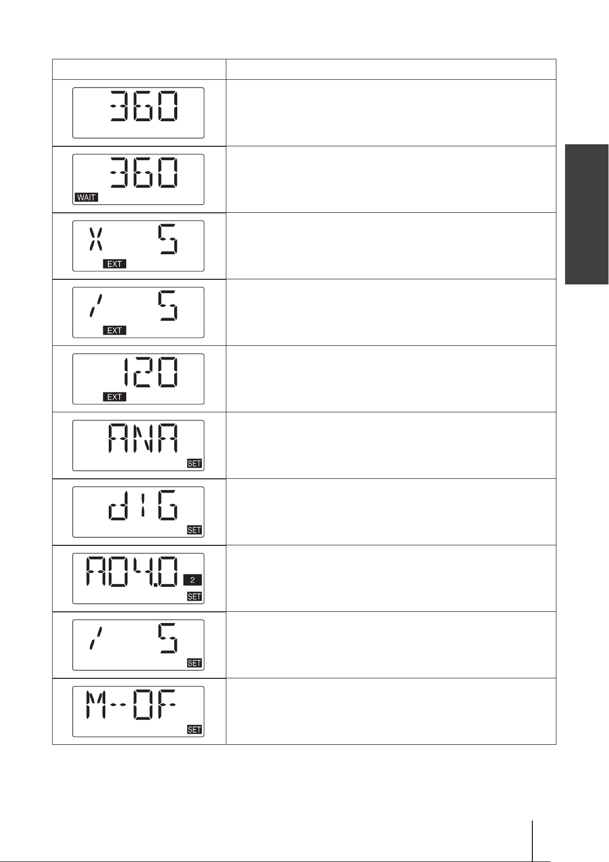
■ Basic displays
Display States
Manual mode. The pump is running at 360spm.
A waiting state. "WAIT" indication appears.
Numerical value shows a MAN speed.
EXT mode with a multiplier 5. The pump is making five shots per
signal.
EXT mode with a divisor 5. The pump is making one short per
5-signal.
EXT mode with analogue signals. The pump is running at 120spm.
Analogue control is selected to EXT mode.
Overview
Digital control is selected to EXT mode.
Analogue control is being set.
Digital control is being set.
M-OF or M-ON is being set for STOP function. An input of STOP
signal stops operation with the left choice (M-OF).
Part names
19
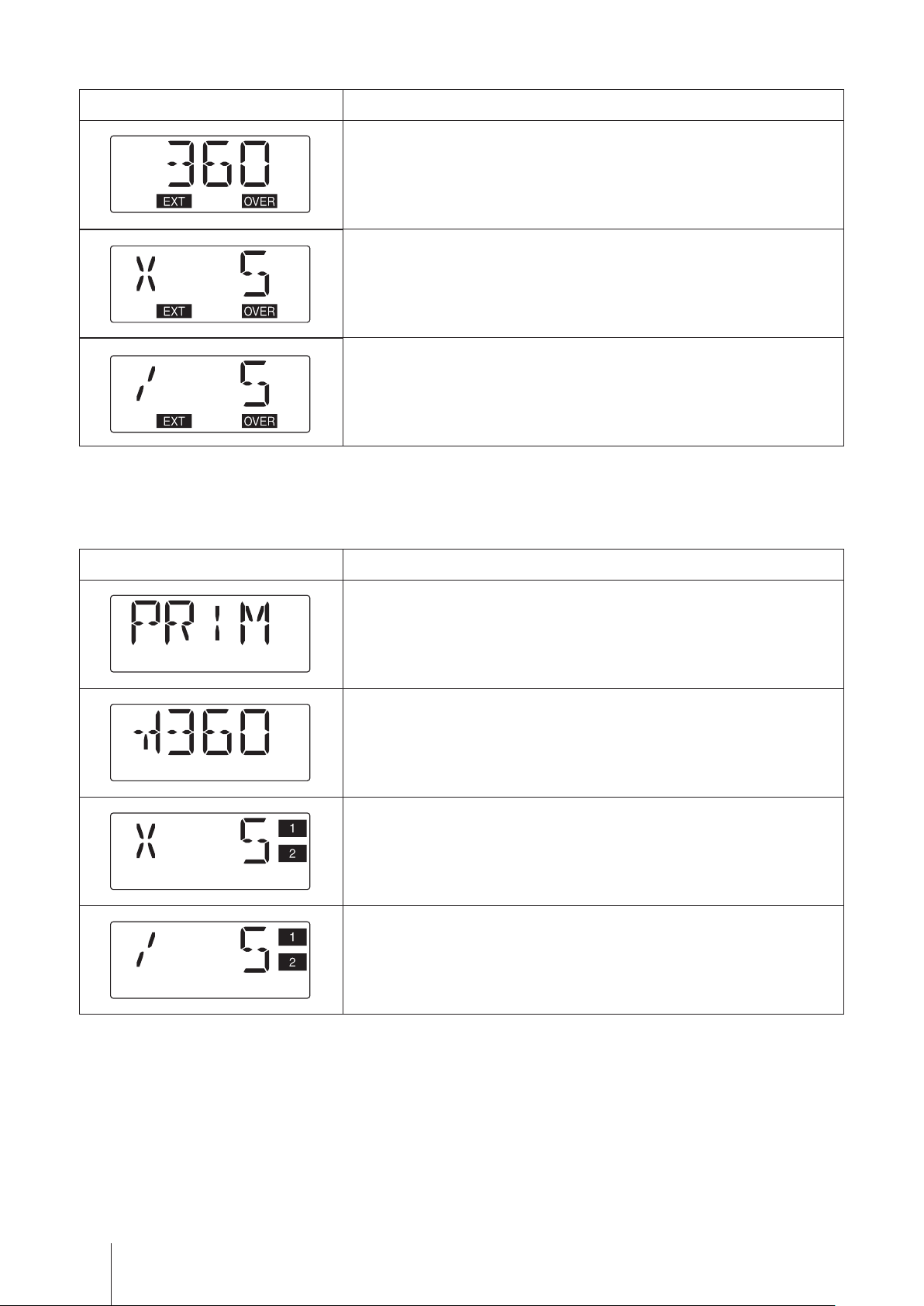
■ Alarm displays
Display States
"EXT" and "OVER" indications appear when the pump is set to run
over 360spm by current signal input under analogue control, however,
the pump does not exceed that maximum rate at any current value.
"EXT" and "OVER" indications appear when the pump under digital
control receives an external signal before the programmed shots per
signal is completed. This unprocessed signal is stored (Max. 255 sig-
nals) and processed in series.
"EXT" and "OVER" indications appear when the pump is set to run
over a MAN speed by pulse signal input under digital control, however,
the pump does not exceed the MAN speed at any number of signals,
storing unprocessed signals (Max. 255 signals).
■ Other displays
Display States
The pump is running at the priming speed (360spm).
Keypad is locked. Any key operation is cancelled. See page 49 to
release this state.
Keypad is locked. Any key operation is cancelled. See page 49 to
release this state.
Keypad is locked. Any key operation is cancelled. See page 49 to
release this state.
20
Part names
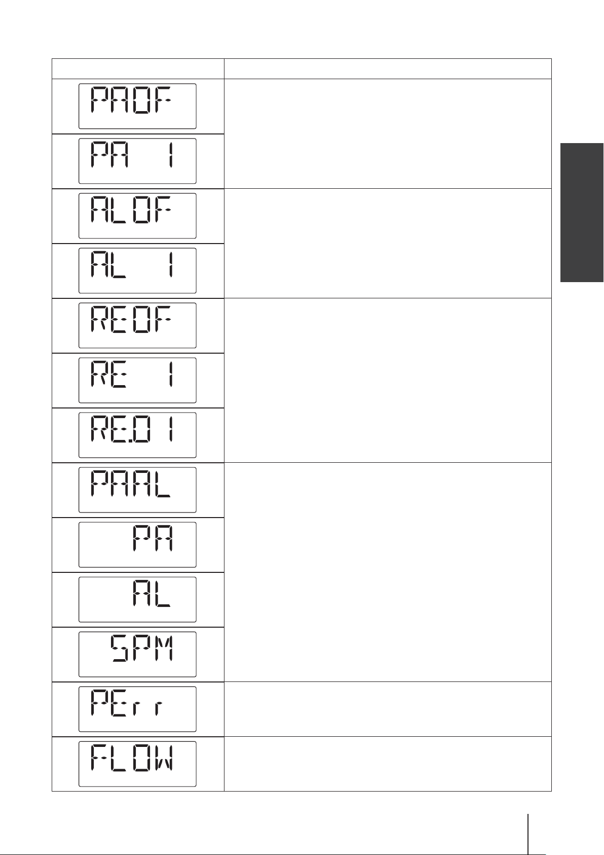
■ Auto restoration displays (FCM type)
Display States
Pre-Alarm time is being set.
Alarm time is being set.
Overview
Return time is being set.
Alarm out is being set.
The pump is running at full speed after the detection of air lock.
The pump has stopped after failing to remove air lock.
Part names
21
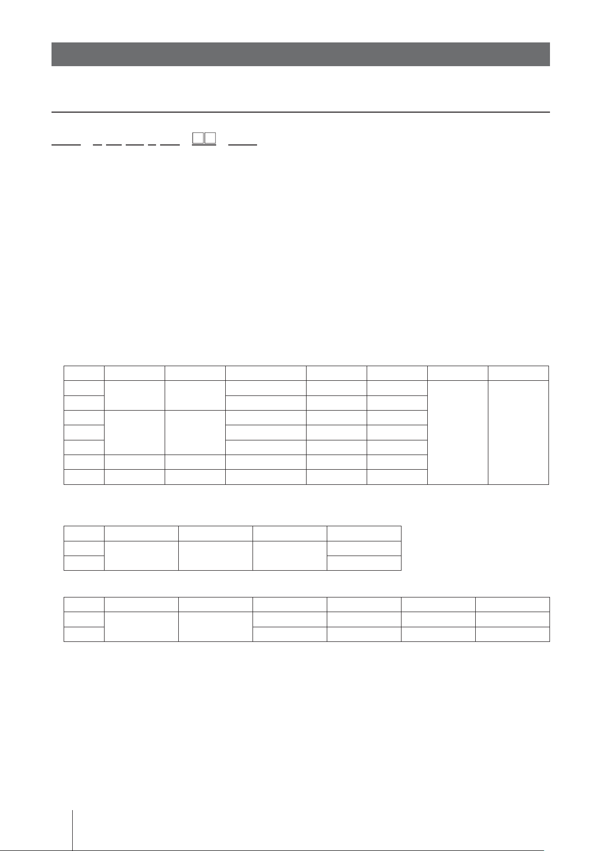
Identification codes
Each code represents the following information.
Pump
EHN - B 11 VC 1 YN - - FCM
a b c d e f g h
a. Series name
EHN : Multivoltage electromagnetic metering pump
b. Drive unit (Average power consumption)
B : 20W
C : 24W
c. Diaphragm effective diameter
11 : 10mm 16 : 15mm 21 : 20mm
31 : 30mm 36 : 35mm
d. Wet end materials
Pump
Code Pump head Fitting Valve O ring Valve seat Gasket Diaphragm
VC
VH HC276 EPDM EPDM
PC
PH HC276 EPDM EPDM
PP Alumina ceramic FKM PCTFE
FC PVDF PVDF Alumina ceramic ― PCTFE
SH SUS316 SUS316 HC276 ― SUS316
*EPDM is not a wet end.
PVC PVC
GFRPP GFRPP
Alumina ceramic FKM FKM
Alumina ceramic FKM FKM
PTFE
PTFE
+EPDM*
Flow checker (FCM type)
Code Body Float Plate O ring
VC
VH EPDM
PVC PVC PVC
FKM
Automatic air vent (Auto degassing type)
Code
Air vent valve guide A Air vent valve guide B
VC
VH HC276 HC276 EPDM EPDM
PVC PVC
Valve Separate pin Valve seat O ring
Alumina ceramic Titanium FKM FKM
Material code
PVC : Transparent polyvinyl chloride GFRPP : Glassfiber-reinforced polypropylene
PVDF : Polyvinylidene difluoride EPDM : Ethylene-propylene rubber
FKM : Fluorine-contained rubber PTFE : Polytetrafluoroethylene
PCTFE: Polymonochlorotrifluoroethyle HC276 : HASTELLOY C276
Identification codes
22
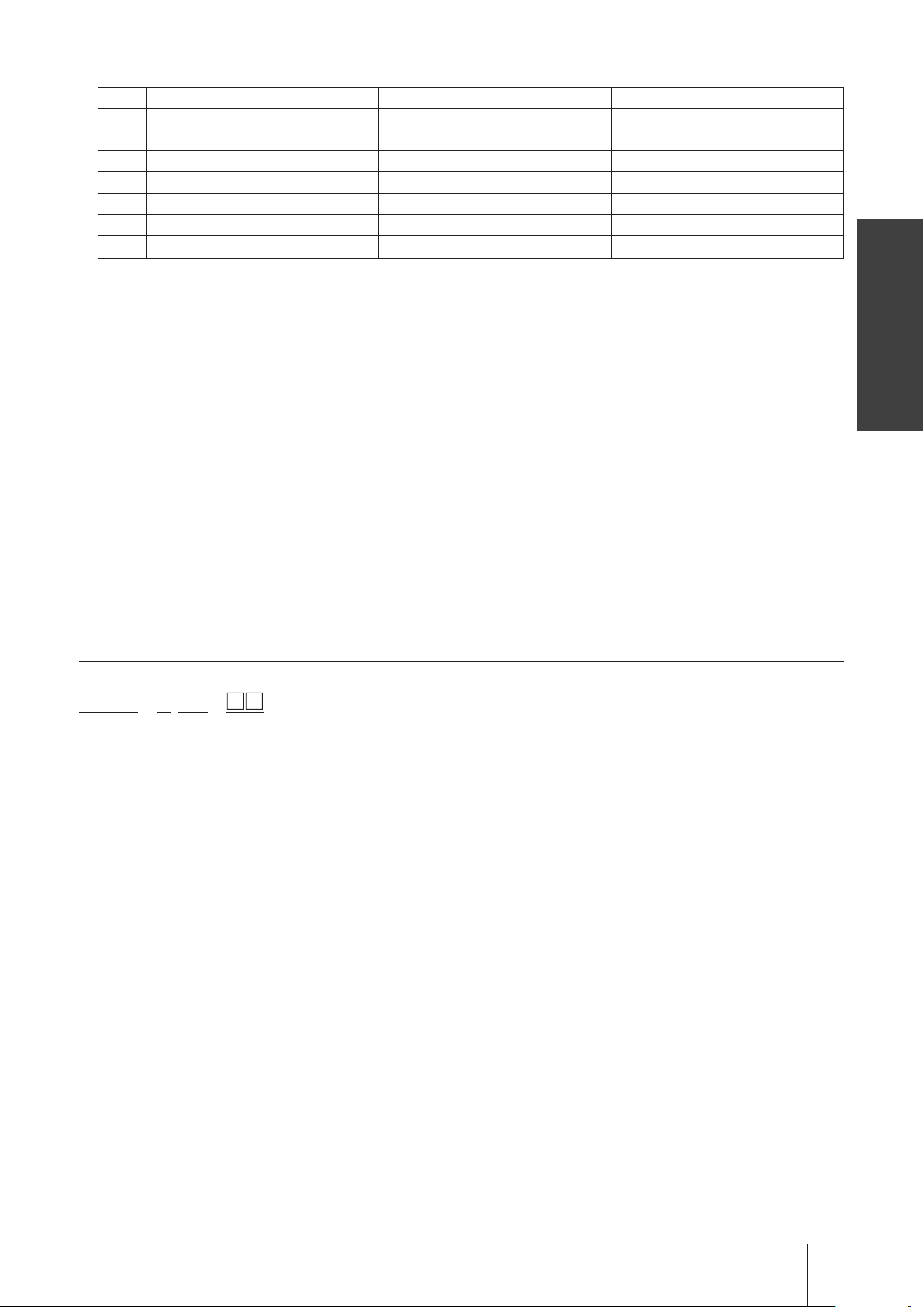
e. Tube connection bore
No. Tube connection bore Tube type Remarks
1 ø4×ø9 PVC braided tube or EVA tube
*
2
*
3
4 ø8×ø13 PVC braided tube or EVA tube
*
5
6ø10×ø12 Teflon tube EHN-31/-36 FC types
9Rc1/4 female thread
* means Special version. Others are standard specifications.
ø4×ø6 Teflon or polyethylene tube EHN-11/-16/-21 FC types
ø6×ø8 Teflon or polyethylene tube
ø9×ø12 Teflon or polyethylene tube
―
All EHN SH types
f. Control unit function
YN : High functional
g. Special version
55 : High compression type
NAE : Auto degassing type
h. Flow checker
FCM : Built-in flow checker (preinstalled or retrofitted)
XFCM: Built-in flow checker (external wiring)
Overview
Control unit
EHNC - B YN -
a b c d
a. Model
EHNC: Multivoltage control unit
b. Drive unit
B : 20W
C : 24W
c. Control unit function
YN : High functional
d. Special version
01-99 : Customized model
Identification codes
23
Installation
This section describes the installation of the pump, piping and wiring.
Read through this section before work.
Points to be observed
Observe the following points when installing the pump.
Be sure to turn off power to stop the pump and related devices before service is per-
•
formed.
If you notice any abnormal or dangerous conditions, suspend operation immediately and
•
inspect/solve problems.
• Do not place explosive or flammable material near the pump.
• Use of a damaged pump could lead to an electric shock or death.
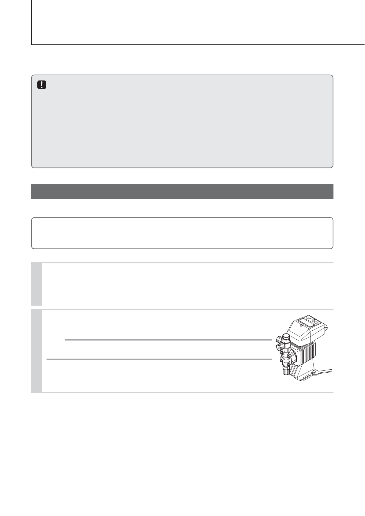
Pump mounting
Select an installation location and mount the pump.
Necessary tools
• Four M5 bolts (pump mounting) • Adjustable wrench or spanner
1
Select a suitable place.
Always select a flat floor free of vibrations and liquid can't stay. See page 10 for detail.
Build up a flooded suction system for the viscous liquid delivery.
Anchor the pump by four M5 bolts.
2
Be sure to fix the pump at four points.
NOTE
Install the pump horizontally. If the pump is installed at a tilt, the flow may reduce.
Pump mounting
24
Plumbing
Connect tubes to the pump and install a check valve.
Before operation
• Cut the tube ends flat.
Necessary tools
• Adjustable wrench or spanner.
Tube connection
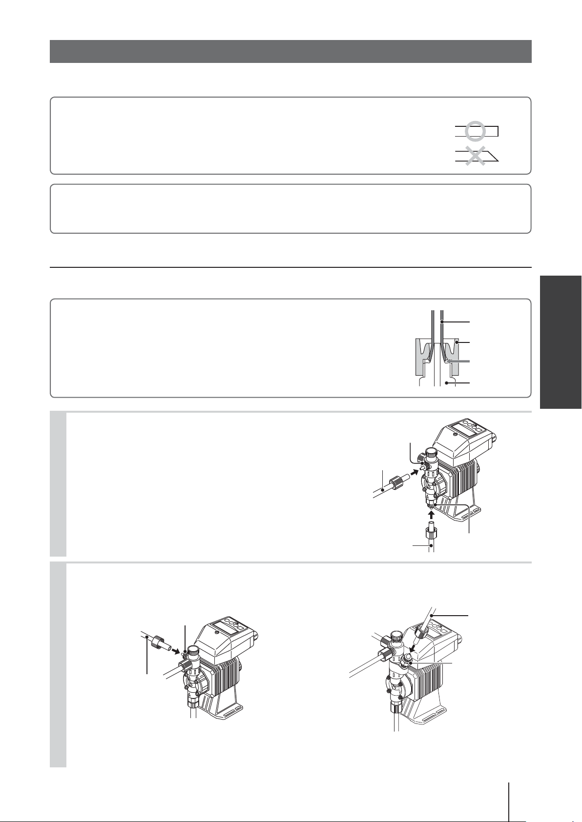
■ VC/VH/PC/PH/PP/FC/SH types
a. Pass a tube into the fitting nut and slide it down to the hose adapter as far as
it will go. Then hand tighten the fitting nut.
b. Turn further the fitting nut 180 degrees clockwise with an adjustable wrench
or spanner.
* The plastic fitting nut may be broken if it is tightened too much.
Tube end (Side view)
Installation
Tube
Fitting nut
Slide it down
Fitting
1
Connect tubes into the inlet and outlet.
Connect an air bleed tube into the air vent port or automatic air vent port (the NAE type).
2
Route back the other tube end to a supply tank or a container.
Air vent port
Air bleed tube
Tube
Outlet
Tube
Inlet
Air bleed tube
Automatic air
vent por t
NAE type
Plumbing
25
3
Determine an air vent port direction.
The air vent port can rotate 90 degrees.
a. Turn the lock nut anticlockwise.
b. Adjust the direction of the air vent port.
c. Hand-tighten the lock nut, holding the air vent body A.
d. Turn the lock nut 90 degrees clockwise further with an adjustable
wrench or spanner.
NOTE
The air vent port is not provided to the EHN-31/-36 and FC types. Install an air
vent valve as the right diagram shows. An optional air vent valve is available ex-
cept for the FC type. See page 73 for detail.
Air vent port
Air vent
valve
Air vent body A
Lock nut
Check valve
Three way joint
Discharge line
Pump
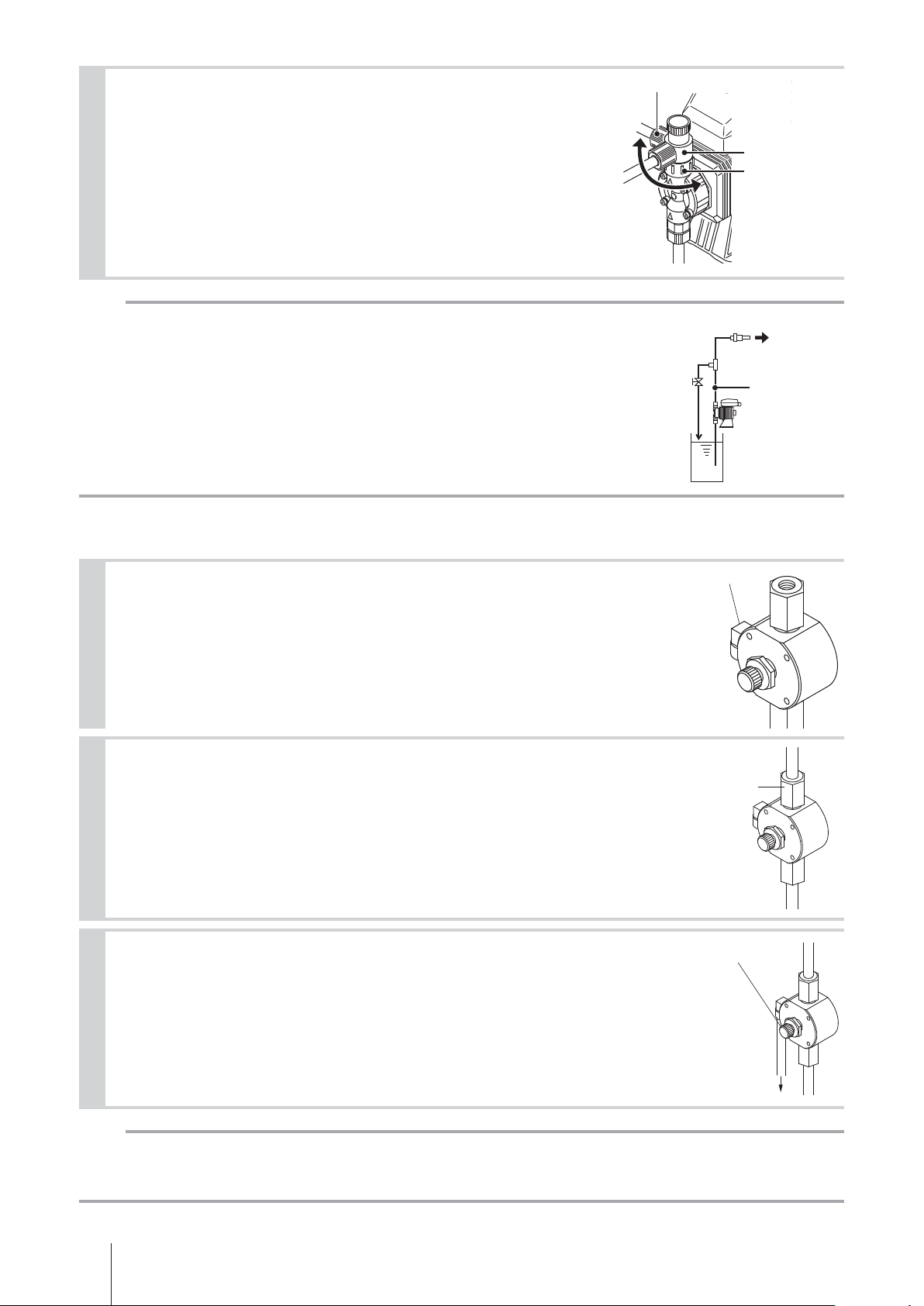
■ SH type
Fit the elbow into the pump head.
1
Wrap a sealing tape to the male thread of the elbow and then screw it into the
threaded hole on the side of the pump head.
Connect a suction and a discharge pipe into the inlet and outlet.
2
The fitting has a Rc1/4 female thread. Connect applicable pipes to the fitting so
as to reduce the possibility of a leak or air ingress.
Connect a ø4mm air bleed tube into the elbow.
3
Route back the other tube end to a supply tank or a container.
Elbow
Fitting
Adjusting screw
Route back to a supply tank.
NOTE
The adjusting screw of the SH type is provided for reducing pressure from the pump head only. It can not re-
lease discharge line pressure. Install air vent valve on a discharge line for depressurization of that line.
Plumbing
26
 Loading...