

IWAKI EHN-B21SH, EHN-C21SH, EHN-C31SH, EHN-B11SH, EHN-SH Series Instruction Manual
...
EHN-SH
Instruction Manual
IWAKI
Electromagnetic Metering Pump
Read this instruction manual before use of product
Thank you for choosing the EHN type electromagnetic metering
pump.
This instruction manual consists of "Safety Section", "Outline
Section", "Installation Section", "Operation Section" and
"Maintenance Section", and deals with the correct installation,
operation, maintenance and troubleshooting procedures.
Please read through this manual carefully to ensure the optimum
performance, safety and service of your pump.
Contents
Instruction for safety
Outline of product 1. Unpacking and inspection
Installation 1. Before installation
Operation 1. Operation
Maintenance Instruction for safety
Exploded view
Outline dimension
...........................................................................
............................
2. Principle of operation
3. Model identification
4. Specif ication
5. Operating function
6. STOP function
7. O ve rview
2. Precaution on handling
3. Installation
4. Tubing
5. Electrical wiring
2. Operation of controller
1. Troubl esh oot ing
2. Maintenance and inspection
3. Wear parts
4. Dismantlement and assembly
..................................................................................
............................................................................
...................................................
.................................................
....................................................
..............................................
...................................................
..................................
.....................................
................................................
.......................................
.............................................
......................................
..........................
...................................
..........................
......................................
...........................................
........................
.......................
10·11
14~18
19~23
24~35
42·43
44·45
1~3
8·9
10
12
13·14
36
37
37
38
Instruction for safety
For the Safe and
Correct Handling of the Pump
●
"Safety Instruction" section deals with important details about
the handling of the product. Before the use of controller, read
through this section carefully for the prevention of personnel
injury or loss.
●
Observe the instructions accompanied with "WARNING" or
"CAUTION" in this manual. These instructions are very impor-
4
4
5
6
7
8
36
tant to avoid dangerous situations.
●
The symbols on this instruction manual have the following
meanings:
Nonobservance or misapplication of the
Warning
Caution
contents of the “Warning” section could
lead to a s er i ou s a cc i de nt w h ic h m ay
result in death.
Nonobservance or misapplication of the
contents of the “Caution” section could
lead to the personal injury to users or
serio us d a m ag e t o t he p ro d uc t.
Types of Symbols
Indicates a prohibited action or procedure. Inside or near this circle, a concrete and practical image of the activity to be avoided is
depicted.
Indicates an important action or procedure which must be performed or carried out without fail. Failure to follow the inst ructions
herein can lead to malf unction or damage to the pump.
- 1 -
Electrical Shock
Prohibited
No Remodeling
Wear protective
gear
Prohibited
Do not wet
or dampen
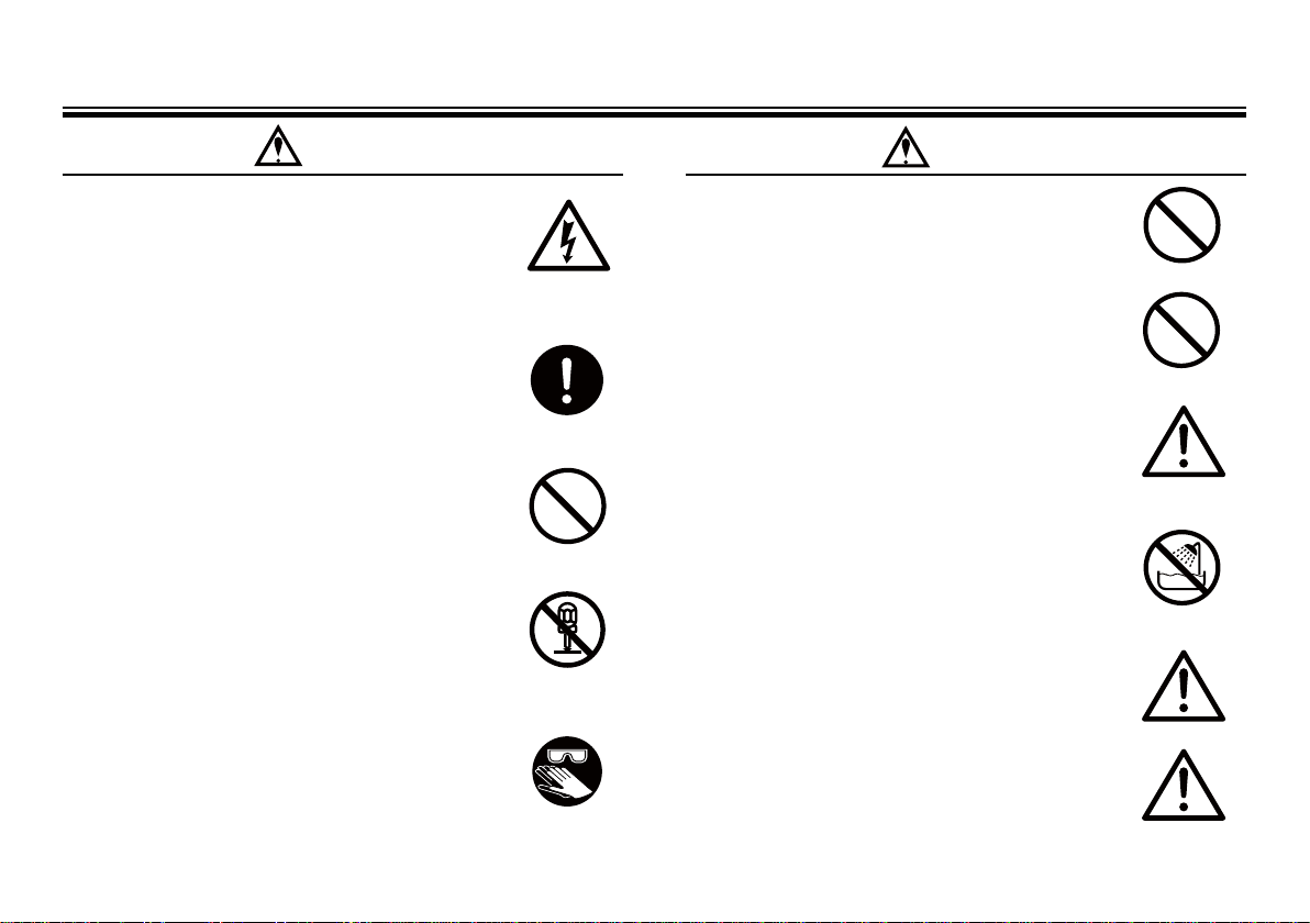
Instruction for safety
Caution
Warning
• Turn off power
Working on the pump with power ON may cause an elec-
trical shock. Before work ing on the pump, make sure to
discon nect the power cord in order to stop the pump and
other related devices.
• Terminate operation
Detecting or becoming aware of any dangerous sig n or
abnormal condition, stop the operation immediately and
resta rt it from the beginning.
• For specified application only
The use of the pump in any application other than those
clearly specified may result in inju ry or damage to the
pump. Use the pump within specifications and applica-
tion range.
• No remodeling
Never try to modif y the pump. Ser ious accidents may
result. We are not responsible for any accident or damage
due to modification without first obtaining permission or
instructions from Iwaki.
• Wear protectors
Always wear protective clothing, eye protection and
gloves before any dismantlement/assembly of the pump
or maintenance.
Caution
• Qualified operators only
Any operation of the pump is permitted to only t he per-
son with a enough understanding of the pump.
• Specified power only
Do not apply any power other than specif ied one on the
nameplate. Otherwise damage or fire will may happen.
• Pay attention to dry running
Do not r un pump dry for more than 30 minutes. The bolt
on the pump head may loosen and result in liquid leak-
age. Install the pump so that dry running can not occu r.
Take extra care not to run the pump dry unintentionally
for more than 30 minutes for air elimination.
• Do not wet or dampen
If any electric part or wiring gets wet with the liquid
spilled over accidentally, a fi re or electrical shock may
be caused. Install the system in a place free f rom liquid
spillage or leakage.
• Ventilate
Poisoning may result when handling toxic or odorous
liquid. Ventilate the operating site suff iciently.
• Spill-out accident
Protective measures should be taken against any acciden-
tal spill-out or leakage of the operating liquid as a result
of unexpected damage on the pump or the related piping.
Prohibited
Caution
Caution
- 2 -
Prohibited
Caution
Prohibited
Electrical Shock
Electrical Shock
Prohibited
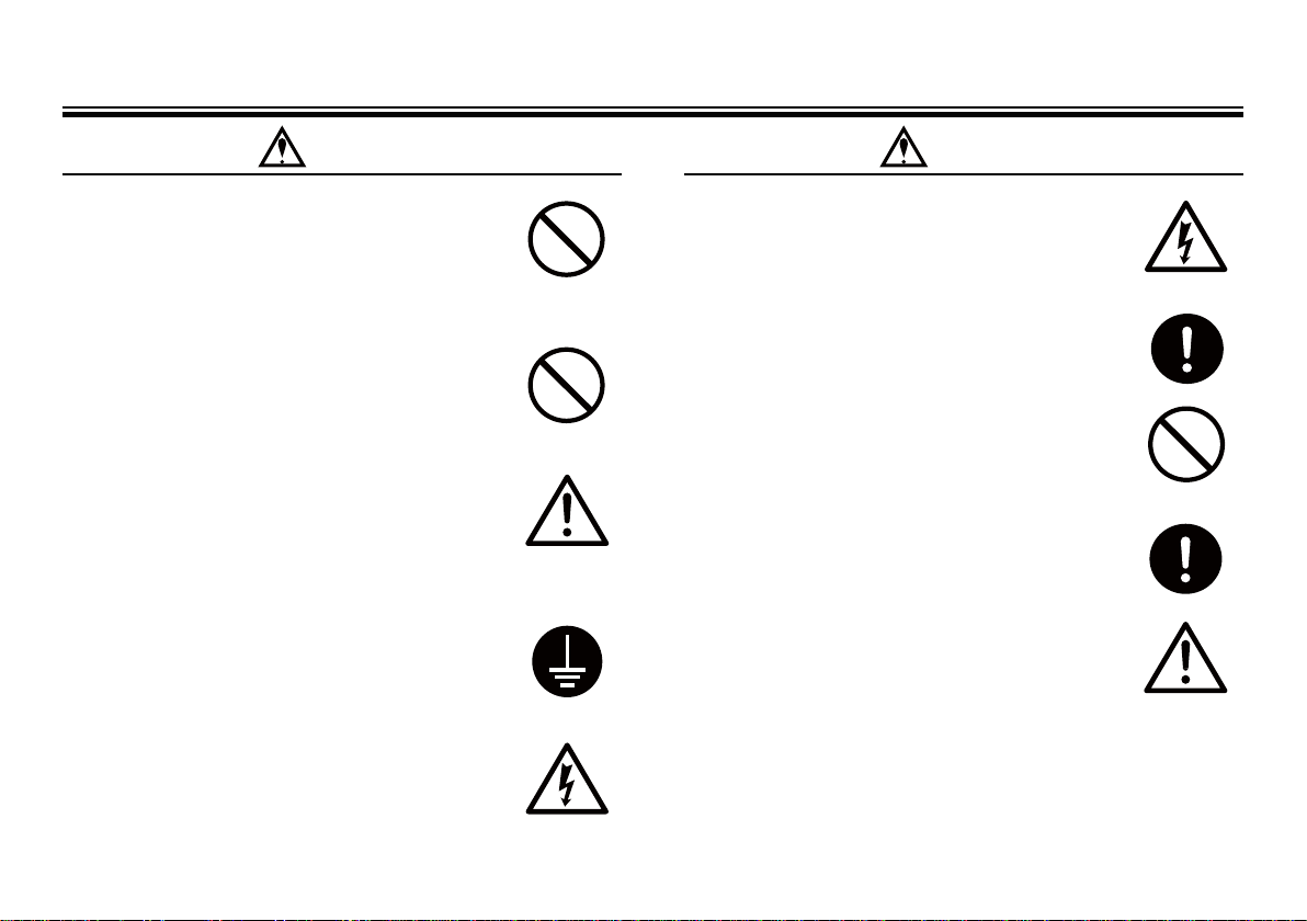
Instruction for safety
Caution
Caution Caution
• Limited operating site and storage
Do not install or store the pump in the following places:
* Flammable gas or material is used or stored.
* Ambient temperat ure is extremely high (40 dig.C or
higher) or ext remely low (0 dig.C or lower).
• Do not place the pump close to water
The pump is not water-proof construction. If the pu mp
is used in a place where liquid is splashed on pump or at
humid place, electrical shock or short-circuit may happen.
• Do not damage or change power cable
Do not scratch, damage, process, or pull the power cable
forcibly. An extra load onto the cable, such as heati ng
the cable or placing something heavy on the cable, may
damage the cable and finally cause a fire or an electrical
shock.
• Arrange grounding
Be su re to connect grounding wire before operation.
Other wise, an electrical shock may result. Make sure the
grounding wire is connected with the grounding terminal.
• Install an earth leakage breaker (option)
Pu mp operation without using an earth leakage breaker
may cause a n electrical shock. Purchase an optional leak-
age breaker and install in the system.
Grounding
• Handling of the power cable
Use of a defective or damaged power cable may result in a
fire or electrical shock. Handle the power cable carefully.
• When replacing parts
Replace the consumable parts by following the descrip-
tions in the instr uction manual. Do not disassemble the
pump beyond the extent shown on the instruction manual.
• Damaged pump
Never operate a damaged pump. A damaged pump may
cause leakage or electrical shock.
• Disposal of used pump
Dispose of the used or damaged pump in accordance with
the relevant local laws and regulations. (Consult a licensed
industrial waste products disposing company.)
• Tightening torque of the pump head
Leakage may occur when the pump head fixing bolts are
loose. Make sure that the pump head is secured by tighten-
ing the 4 f ixing bolts diagonally at the first operation.
Tightening torque
EHN-B11 • 21 • C21 : 2.16N•m
EHN- C31 • 36 : 2.55N•m
- 3 -
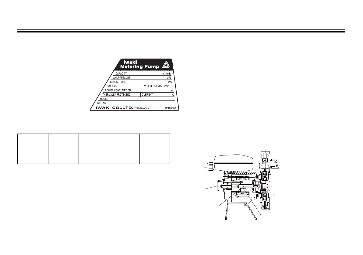
Outline of product
Control unit
Pump head
Driving unit
Stroke length
adjusting knob
Plunger
Diaphragm
Spring
1. Unpacking and inspection
1) Check the model code, discharge capacity, discharge
pressure and voltage etc.
shown on nameplate to
confirm the pump is in your
specification.
2) Check if accessories are
attached.
a. Check valve or back pres-
sure valve : One piece
Model
CS-1S 0.2
CS-1SL
Set press.
MPa
Connection Wet-end material
SUS316
RC1/4
Hastelloy C
PTFE
Applied pump
model
EHN-B11ּ21
EHN-C21ּ31
EHN-C360.05
3) Check if the product is not damaged and any parts are not lost in
transit. Check that any bolts or nuts are not loosened.
If you find any abnormality, ask us.
2. Principle of operation
IWAKI electromagnetic metering pump the EHN series is a diaphragm metering pump which consists of a pump head, driving unit,
and control unit. A diaphragm is directly driven by electromagnet
force.
A reciprocating motion is made by a spring and electromagnetic
force generated by pulse current coming from a control unit. The
reciprocating motion is transferred to a diaphragm through a plunger
and makes volumetric change in a pump chamber. Pumping action is
obtained by volumetric change and by valve action in pump head.
- 4 -
Outline of product
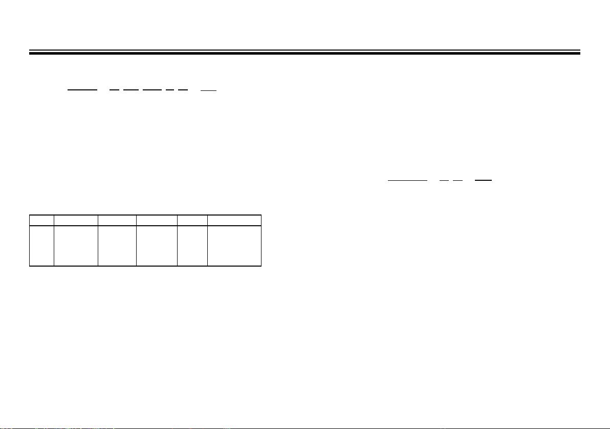
3. Model identification
Pump : EHN - B 11 SH 9 R -
□□
1 2 3 4 5 6 7
1. Series
EHN multi voltage type
2. Driving unit code (Average power consumption)
B : 20W C : 24W
3. Diaphragm effective diameter
11 : 10mm 21 : 20mm
31 : 30mm 36 : 35mm
4. Wet-end material
Code Pump head Valve Valve seat Gasket
SH SUS316
Mate rial code EPDM: Ethylene-propylene-diene-methylene P TFE: Poy tetr aflu ro ethylene
Hastelloy C
SUS316 PTFE
Diaphragm
PTFE
+
EPDM
(Not wet-end)
5. Connection hose diameter code
9: Rc1/4 Female screw
6. Controller function code
R: Standard type
7. Special type code
01 ~ 99 : Non standard material, Non standard connection, etc.
Control unit : EHNC - B R -
□□
1 2 3 4
1. Control unit type
EHNC: Multi voltage type (with crimp contact)
2. Driving unit code
B or C
3. Controller function code
R: Standard type
4. Special type code
01 ~ 99 : Non standard specification.
- 5 -
Outline of product
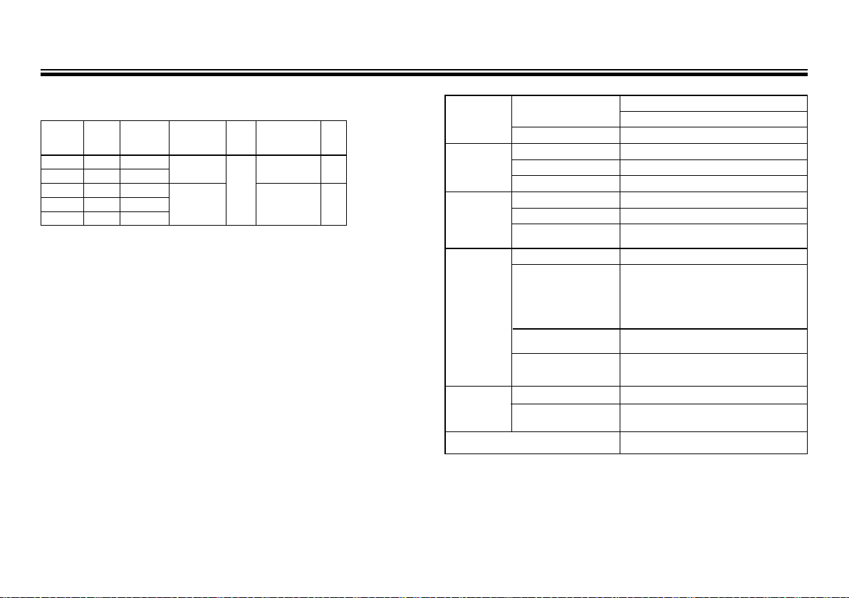
4. Specification
4-1. Pump specification
Disch.
capacity
ml/min
notice.
Max. disch.
Model
EHN-B11 38 1.0
EHN-B21 100 0.4
EHN-C21 130 0.7
EHN-C31 270 0.35
EHN-C36 410 0.2
Note1. Per formance is obtained by pumping clean water at ambient temp in the
rated voltage.
2. Discharge capacity on the table are obtained at max. discharge pressure
(100% stroke length, 360 spm stroke rate.). When discharge pressure
is low, the pump discharges liquid much more than discharge capacity
shown as above.
3. Permissible ambient temperature : 0 ~ 40 deg. C
4. Permissible liquid temperature : 0 ~ 40 deg. C
5. Permissible voltage fluctuation: Within ±10% of the rated voltage
● Ask us for special cases such as transferring slurry liquid or so.
● Specification may be changed for product improvement without prior
press.
MPa
Stroke length
mm
(%)
0.5~1.0
(50~100)
0.5~1.25
(40~100)
Stroke
rate
spm
1~360
Average power
consumption
W
20
24
Mass
kg
2.4
4.1
4-2. Control unit
Operation
mode
Stroke rate
STOP input
EXT input
Display
Power source voltage
Note 1: Max. charged voltage to the contact is 12V and 5mA current. If the con-
tact such as relay is used, its applicable load should be 5mA or below.
Note 2: The input signals over the upper limit stroke rate are stored up to 255
signals.
Note 3: The residual input signals over 360 spm are cancelled.
Note 4: Do not apply any voltage other than the specified one. It causes the
pump failure. Allowable power voltage is between AC90 - 264V.
Mode
Switching Key operation
Set range 1 ~ 360 spm
Set method Up or down key
Memory function By non-volatile memory
When M - OFF Pump stops when contact signal comes.
When M - ON Pump runs when contact signal comes.
Input signal
Upper limit stroke rate Stroke rate indication of manual mode
Pump operation
Input signal
Dividing ratio/Multiply
ratio setting range
Figures
Pump movement
EXT(Pule dividing or multiply )
Potential free contact or open collector
1 input signal : "n" pumping(s)
"n" input signal(s) : 1 pumping
When "n" is 1, the pump starts synchronized operation
Potential free contact or open collector
(Blinks synchronous with pump operation)
AC100V~240V, 50/60Hz Note 4
Manual
Note 1
(Pulse multiply) Note 2
(Pulse dividing) Note 3
Note 1
1~999
(Dividing or multiply)
4 digits LCD
Green LED (one)
- 6 -
Outline of product
Pump operation
Operation Operation
Stop
Key operation
EXT input(Multiply)
×
n operation (n=5)
External pulse
Pump operation
1
2 3 4
5 1 2
3
4 5
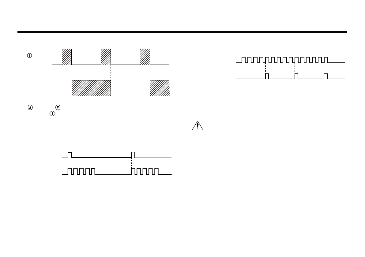
5. Operating function
5-1. Manual operation
Use (UP) and (DOWN) keys to set a stroke rate between 1 ~
360 spm. Use (Stop/start) key to start/stop the pump. Stroke rate
can be adjusted when the pump runs or stops.
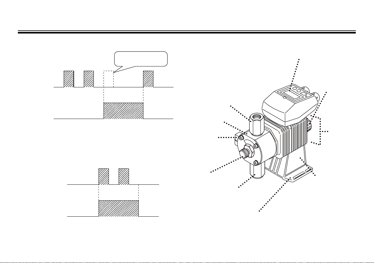
5-2. EXT operation
EXT input (Multiply) when a set number of pumping is 5
EXT input operation (Pulse multiply)
Pump operates with a set number of pumping between 1~999 for a
external pulse signal. The preset stroke rate in manual operation is
applied as the upper limit stroke rate in EXT operation. The pulse
signals which come while pumping for the set number of times for
a external pulse signal are stored up to 255 pulses. When the set
number of pumping is set to 1, pump operates synchronously with a
external pulse in the ratio of 1:1.
EXT input (Dividing) when a set number of pumping is 5
EXT input(Dividing) /n operation (n=5)
External pulse
1 2 3 4 5
1 2 3 4 5 1 2 3 4 5
Pump operation
EXT input operation (Pulse dividing)
Pump operates with a pumping for external pulse signals. The preset
stroke rate in manual operation is applied as the upper limit stroke
rate in EXT operation. Residual input signals over 360 spm are
cancelled. When the set number of external signals is set to 1, pump
operates synchronously with a external pulse in the ratio of 1:1.
Caution
When the set number of external pulse signals for a pumping
is set to 1 in pulse dividing operation, pump operation can be
unstable due to the residual signal cancellation function but it
is not malfunction of pump. Set the number of pumping for a
external pulse signals to 1 for 1:1 operation in the pulse multiply
operation.
- 7 -
Outline of product
6. STOP function
6-1. M – OF setting
Pumps does not operate
because of STOP signal.
Pump operation
STOP signal
The pump stops while STOP signal is comming(contact closed).
The pump starts running when STOP signal is stopped.
6-2. M – ON setting
Pump operation
STOP signal
Pump operates while STOP signal comes (contact closed). The pump
operates in EXT mode while STOP signal is coming.
7. Ove r view
7-1. Overview of pump
Discharge port
Pump head
Bleed port
Be sure to connect
a tube and return it
to the suction
side tank.
Adjusting
screw
Suction port
Control unit
For the pump operation,
the flow rate adjustment
and the st roke rate
adjustment·setting.
Stroke length
adjustment
knob
Driving unit
Pay attention
to mounting
location.
Do not have
them wet.
Nameplate
Use the pump
according to the
specif ication on
the nameplate.
Base
Fix base with screws.
- 8 -
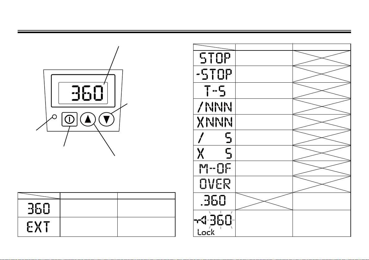
Outline of product
ON
STROKE RATE
Start/Stop key
Use this key to
start/stop the pump.
Down key
Pu sh t his key t o
ch ange mo de or
se tt ing val ue.
Display
Operation state or
ea ch setting value a re
displayed.
Up key
Pu sh t his key t o
ch ange mo de or
se tt ing val ue.
7-2. Overview of controller
ON lamp lights ON lamp blinks
The pump is waiting in
manual operation mode.
The pump is in E XT mode.
EXT setting can be done.
The pump is running in
manual operation mode. The
stroke rate blinks, too.
The pump is running in EXT
mode.
7-3. Basi c disp lay.
( )
- 9 -
ON lamp lights.
The pump is stopped by
STOP signal..
The pump is stopped in
manual waiting mode while
STOP signal comes.
Chattering is being set.
T-10 or T-50 is displayed
other than T-5.
Pulse dividing mode is
selected in EXT setting.
Pulse multiply mode is
selected in EXT setting.
The dividing ratio of EXT mode
is being set. The left display
shows 1 pum ping for 5 pulses .
The multiply ratio of EXT mode
is being set. The left display
shows 5 pumpings for a pulse.
STOP function is set to
M-OF. M-ON is displayed
when M- ON is selected.
EXT input signals exceed the
pump uppe r limit spm in EX T
mode. Pum p operates at its
upper limit spm.
Key is locked. Key operations are ineffective in this
state. Release the key lock
function before operation.
ON lamp blinks.
Pump is running in pulse dividing/multiply operation for external input pulses. The indication
shows spm .
Key is locked. Key operations are ineffective in this
state. Release the key lock
function before operation.
Installation
1. Before installation
"Strictly observe the following points."
Operators and maintenance service staff must read the instr uction
manual thoroughly before installing the products. Do not operate the
pump system unless all of the contents in this manual are completely
understood.
Warning
●
Turn off power
Working with power ON may cause an electrical shock. Before
working on the pump, make sure turn off main power.
●
Terminate operation
On detecting or becoming aware of any dangerous sign or abnor-
mal condition in operation, terminate the operation immediately
and start it from the beginning again.
●
Specified power only
Be sure to connect earth wire. Do not apply any power other than
specified power on nameplate.
●
Keep the pump away from heat or flame
Do not place any dangerous materials or flammable objects near
the pump for the prevention of fire or accident.
●
Damaged pump
Never operate any damaged pump. A damaged pump may cause
leakage or electrical shock.
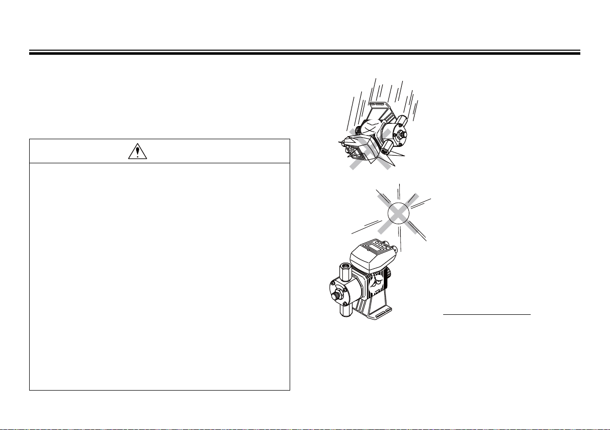
2. Precaution on handling
●
Dropping the pump or subjecting
it to strong impacts may result in
faulty performance. Handle the
pump with care.
●
When installing the pump, avoid
places where...
• The pump is exposed to direct
sunlight or rain.
• Ambient temperature is 40 deg.
C or more.
• Relative humidity is 85% or
more.
Though the pump has a simple
waterproof and dustproof structure,
do not install it outdoor.
●
Select an installation site convenient
for future maintenance and inspection, and fix the pump on a flat
floor free of vibrations.
- 10 -
Installation
Prohibited
Prohibited
Benzine
Thinner
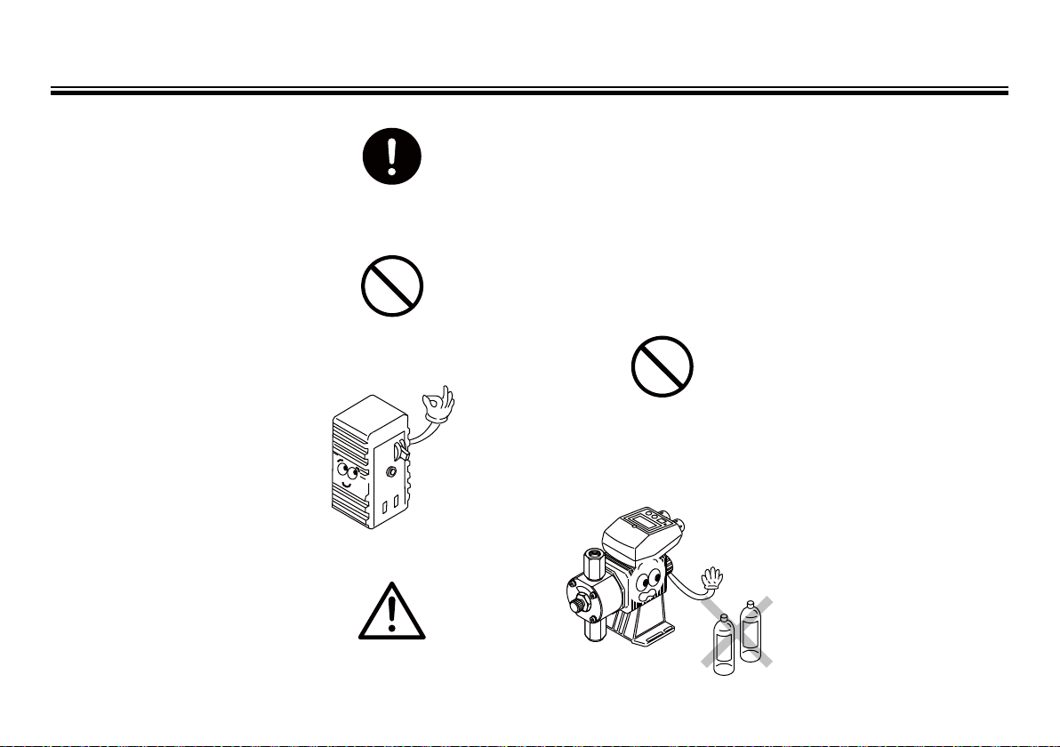
●
Ventilate.
Poisoning may result when
toxic or odorous liquid is used.
Ventilate the operating site sufficiently.
●
Do not wet or dampen.
If an electric part or wiring gets
wet with the liquid spilled over
accidentally, a fire or electrical
shock may be caused. Install
the system in a place free from
liquid spillage or leakage.
●
Install an earth leakage
breaker (option).
Pump operation without an
earth leakage breaker may lead
to an electrical shock. Purchase
an optional leakage breaker and
install in the system.
●
The control unit can be
detached, however, do not
detach it unless it is not
required. Never use the detached
control unit with other pump
models.
Caution
- 11 -
●
Grounding.
Risk of electrical shock. Do
not operate the pump without
grounding.
●
Limited operating site and
storage
Do not install or store the
pump in the following places:
• Flammable gas or material is
used or stored.
• Ambient temperature is
extremely high (40 deg.C or
higher) or extremely low (0
deg.C or lower).
• Under direct sunlight or
rainwater
• Relative humidity is 85% or
more.
●
Cleaning
Do not wipe the pump body
or the nameplate with a cloth
soaked with solvent such as
benzene, thinner, or kerosene.
Coating may be removed or
colour may be changed. Use
a dry cloth or a cloth soaked
with water or neutral detergent.

Installation
3. Installation
Caution
Detecting or becoming aware of a dangerous sign or abnor-
mal condition in operation, stop the operation and take the
procedure from the top.
●
Installation
Install the pump at a site where
ambient temperature does not
exceed 40 deg.C and relative
humidity does not exceed 85%.
(There should be no dew condensation in the control unit.)
The site must be selected keeping in mind ease and efficiency
for maintenance and inspection
work.
Do not expose the pump to
sunlight or rainwater. Cover the
pump when placing it outside.
●
Place the pump as close to the
suction tank as possible.
Caution
●
If the pump is used to feed any
liquid that generates air bubbles easily (Hydrazine solution,
etc.), it must be positioned in
a cool, dark place away from
direct sunlight.
When using a tank, realize a
flooded suction system.
●
Anchoring pump
Select a flat floor free of liquid
splash for installation of the
pump. Use M5 bolts to f irmly
anchor the pump so as not to
allow any vibration.
- 12 -
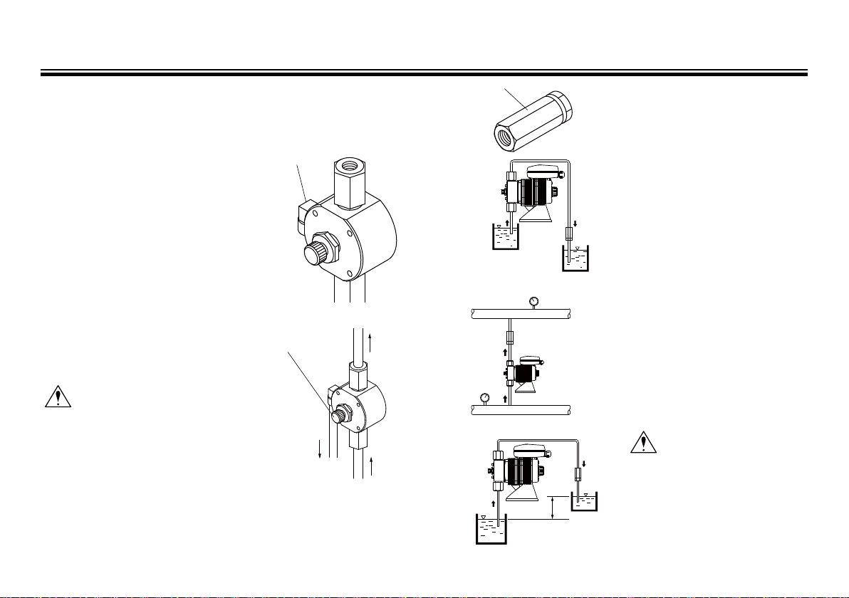
Installation
Fig.C
5m
Suction side tank
Discharge side tank
Bleed port
Check valve
OUT
IN
Fig.B
Discharge
Suction
Return the end
tube to a tank.
Adjusting screw
4. Tubing
1) Tape the air bleeding union
(Attached to the pump) and screw it
in the pump head.
2) Have the piping short and less
bends as much as possible to reduce
flow resistance.
3) The fitting bore is Rc1/4 female
thread. Be sure to connect each
connection on both suction/discharge piping to eliminate liquid/
air leakage.
4) Piping for air elimination.
Be sure to return the end of hose to
a tank or container after connecting a hose to the bleed port.
Caution
Regarding the SH type, discharge
pressure can not be fully opened
by the adjusting screw. Install a
discharge valve on discharge pipe
for opening pressure.
- 13 -
Suction side tank
Fig.A
5) Mounting check valve
A check valve is packed to
avoid over feeding. Be sure to
install the check valve in following condition.
a. Suction side liquid level is
higher than discharge side
liquid level. (See Fig. A)
Injection point is below
suction side liquid level at
atmospheric pressure.
Discharge side tank
b. Suction side pressure is
higher than that of injection
point. (See Fig. B.)
c. Difference of liquid level in
height is 5 meters or less,
even if discharge side liquid
level is higher than suction
side. (See Fig. C.)
Caution
Periodically wash or replace
the check valve with new one
because it may be clogged by
crystal.

Installation
Power
When power is charged at a setting When power is charged gradually
ON
OFF
Power
ON
OFF
d. Discharge pressure (Pipe
resistance, discharge head or
so) is below 0.13MPa. (Load
pressure is 0.049MPa for C36).
• The check valve should be
installed at discharge tube end at
least 1 meter away from pump.
5. Electrical wiring
Caution
Electrical works must be done by a qualified person. We are
not responsible for any injury and damage by any person
other than a qualified person,
5-1. Wiring of power source
1) Confirm that main power source is tur ned off before wiring.
2) Wiring must be done according to your electrical works standard
using good wiring equipment/device.
Caution
Power voltage should be charged at a sitting via switch or
relay. Otherwise malfunction of CPU may happen.
For selecting a relay, refer to P16 which mentions the precaution
when pump is controlled by relay ON/OFF.
- 14 -
 Loading...