

IWAKI EH-E 31, EH-E 56, EH-E 36, EH-E 46 Instruction Manual

Read this manual before use of product
IWAKI
Electromagnetic Metering Pump
EH-E Type
Instruction Manual

Contents
IMPORTANT INSTRUCTION
..........................................................
1
Safety Instruction
............................................................................
2
Outline
...........................................................................................
5
1. Unpacking
...............................................................
6
2. Operating Principle
.................................................
6
3. Identification Code
..................................................
7
4. Features
.................................................................
9
5. Specification
.........................................................
10
6. Operating Function
11
7. Display and Keys
..................................................
13
Installation
.....................................................................................
16
1. Notes on Installation
.............................................
17
2. Location
................................................................
19
3. Tubing
...................................................................
20
4. Electrical Wiring
....................................................
23
Operation
......................................................................................
27
1. Preparation for Operation
......................................
28
1-1. Bleeding
........................................................
28
1-2. Adjustment of Discharge Capacity
................
30
2. Operation
..............................................................
32
2-1. Overview Operating Scheme
........................
32
2-2. Setting and Operation of Controller
...............
34
Maintenance
..................................................................................
44
1. Troubleshooting
....................................................
45
2. Maintenance and Inspection
.................................
46
3. Disassembly and Assembly
..................................
49
4. Optional Accessories
............................................
53
5. Exploded Views and Dimension Drawing
..............
53
Thank you for selecting the electromagnetic metering pump EH-E series. This instruction
manual deals with “Safety Section” “Product outline” “Installation Section” “Operation
Section” and “Maintenance Section”.
Please read through this manual carefully to ensure the optimum performance, safety and
service of the EH-E series.
-
1 -
Important instructions
Export Restrictions
Information contained within this instruction manual may be considered controlled technol-
ogy as set by the Japanese Ministry of Economy, Trade and Industry (METI). An export
license issued by METI may be required when exporting or providing the manual to a 3rd
party.
Nonobservance or misapplication of “Caution” sections could lead to personal injury or property damage.
For the Safe and
Correct Handl ing of the Pump
●
"Safety Inst r uct ion" section deals with important details about handl ing of the product. Before
use, read this section carefully for the prevention of personal injury or property damage.
●
Observe the instructions accompanied with "WARNING" or "CAUTION" in this manual. These
instructions are very important for protecting users from dangerous situations.
●
T he s ymb ol s o n t his ins truc tion m anu a l h a ve t h e fol lowi ng m e a ni n gs:
WARNING
Nonobservance or misapplication of “Warning” sections could lead to a serious accident which may
result in death.
CAUTION
Types of Symbols
Indicates that “Warning” or “Caution” must be exercised. Inside this triangle, a concrete and practical im age provided as a warn i ng or caution message is depicted.
Indicates a prohibited action or procedure. Inside or near this circle, a concrete and
practical image of the activity to be avoided is depicted.
Indicates a n i mp or t a nt act ion or pro cedure which must be pe r for med or ca r r ied out
without fail. Failure to follow the instr uctions herein can lead to malf unct ion or
damage to the pump.
-
2 -
WARNING
● Wear protectors
If you touch or come in contact with any type of hazardous chemical liquid, including
but not limited to chemicals, you may experience a serious injury. Wear protective
gear (protective mask, gloves, etc.) during the pump operation.
● Turn off the power supply
Working without disconnecting the power supply cause an electrical shock. Before
engaging upon any working procedures involving the pump, make sure to turn the
power supply switch off and to stop the pump and other related devices.
● Terminate operation
When you detect or become aware of a dangerous sign or abnormal condition during
operation, terminate the operation immediately and start from the beginning again.
● For specified application only
The use of a pump in any application other than those clearly specified may result
in injury or damage to the pump. Use the pump strictly in accordance with the pump
specifications and application range.
● No remodeling
Never remodel a pump. Otherwise, a serious accident may result. Iwaki will not be
responsible for any accident or damage of any kind which is caused by the user
remodeling the pump without first obtaining permission or instructions from lwaki.
● Operating site must be free of water and humidity
The pump is not designed to be water-proof or dust-proof. The use of the pump in
places where water splashes or humidity is high may result in an electrical shock or
short circuit.
Safety instructions
No Remodelin
g
Prohibited
Electrical Shock
Prohibited
Wear protective
gear
-
3 -
CAUTION
● Spill-out accident
Protective measures should be taken against any accidental spill-out or leakage of
the operating liquid as a result of unexpected damage on the pump or the related pip-
ing.
● Qualified operators only
The pump operator and pump operation supervisor must not allow any operators who
have little or no knowledge of the pump to run and operate the pump. Pump operators
must have a sound knowledge of the pump and its operation.
● Specified power only
Do not operate the pump on voltage which is not specified on the nameplate. Failure
to do so may result in damage or fire. Only the specified power level is to be applied.
● Do not run the pump dry
Do not run the pump dry (without liquid inside the pump). Heat generated as a result
of abrasion between elements inside the pump during operation without liquid may
damage the inside of the pump.
● Do not wet or dampen
If an electric part or wiring gets wet with the liquid spilled over accidentally, a fire or
electrical shock may be caused. Install the system in a place free from liquid spillage
or leakage.
● Frequent stop and start of pump should be done by using STOP function (ON and
OFF of STOP terminal). If you can not use STOP function and are forced to operate
pump by turning OFF and ON of power source, ON and OFF of power source should
be limited to six times an hour.
● Ventilate
Poisoning may result during an operation which involves, toxic or odorous liquid.
Ventilate the operating site sufficiently.
● Damaged pump
Never operate a damaged pump. A damaged pump may cause leakage or electrical
shock.
● Do not damage or change power cable
Do not scratch, damage, process, or pull the power cable forcibly. An extra load onto
the cable, such as heating the cable or placing something heavy on the cable, may
damage the cable and finally cause a fire or an electrical shock.
Safety instructions
Prohibited
Prohibited
Prohibited
Do not wet
or dampen
Prohibited
Caution
Caution
Caution
-
4 -
CAUTION
● Arrange grounding
Do not operate the pump without connecting the grounding wire. Otherwise, an elec-
trical shock may result. Make sure the grounding wire is connected with grounding
terminal.
● Install an earth leakage breaker
The operation of a pump without using an earth leakage breaker may cause an elec-
trical shock. Please install a leakage breaker in the system.
● Handling of power cable
Use of a defective or damaged power cable may result in a fire or electrical shock.
Handle the power cable carefully.
● Follow the instruction manual
Replace the consumable part by following the descriptions in the instruction manual.
Do not disassemble any part of the pump if the disassembling procedure for the part
in question is not included in the instruction manual.
● Disposal of used pump
Disposal of used or damaged pumps must be done in accordance with the relevant
local law and regulations. (Consult a licensed industrial waste products disposing
company.)
● Limited operating site and storage
Do not install or store the pump in the following places :
Places where a flammable gas or material is used or stored.
Places where the ambient temperature is extremely high (40 °C or higher) or extreme-
ly low (0 °C or lower).
Safety instructions
Electrical Shock
Prohibited
Electrical Shock
Grounding

-
5 -
1. Unpacking
...........................................
6
2. Operating Principle
.............................
6
3. Identification Code
..............................
7
4. Features
.............................................
9
5. Specification
.....................................
10
6. Operating Function
...........................
11
7. Display and Keys
..............................
13
Outline
-
6 -
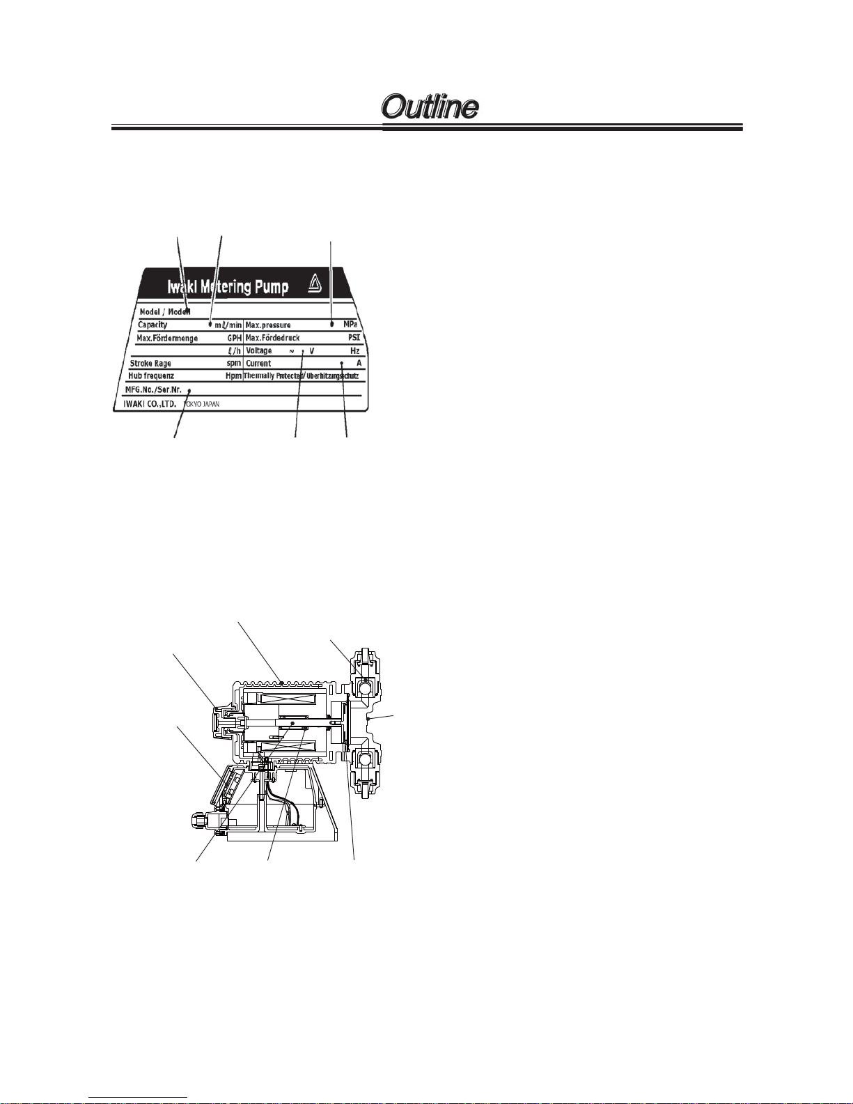
After unpacking the goods, check the following
points to ascertain that the product is exactly as
you ordered.
If you find anything wrong, please get in touch with
your dealer.
(1) Do the model, voltage, etc., shown on the
nameplate represent what you ordered?
(2) Has the goods been damaged in transit? Are
the bolts and nuts loose?
The EH Series electronic metering pump consists
of a pump unit, a drive unit, and a control unit. The
drive unit is an electromagnetic solenoid. When the
solenoid coil is energized by the control unit the
armature shaft moves forward due to the magnetic
force of the solenoid. The shaft is attached to a
PTFE faced diaphragm which is part of the pump
unit. The diaphragm is forced into the pump head
cavity decreasing volume and increasing pressure
which forces liquid in the pump head out though
the discharge check valves. When the solenoid
coil is de-energized, a spring returns the armature
to its starting position. This action pulls the dia-
phragm out of the head cavity increasing volume
and decreasing pressure. Atmospheric pressure
then pushes liquid from the supply tank through
the suction check valves to refill the pump head.
Control unit
Stroke length
adjusting dial
Drive unit
Pump
head
Valve
SpringPlunger Diaphragm
Outline
1. U n p a c k i n g
2. Ope rating Principle
Model
Capacity
Max. Pressure
Manufacturing number
Voltage Current
-
7 -
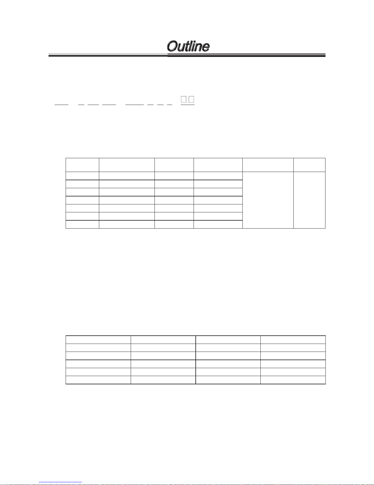
3. Identification Code
• Pump identification
EH - E 31 PC - 23U P E 8 -
(1) (2) (3) (4) (5) (6) (7) (8) (9)
(1) Series name EH Series
(2) Drive component E : 48 W
(3) Diaphragm effective diameter 31 : 30 mm 36 : 35 mm 46 : 45 mm 56 : 55 mm
(4) Material of liquid end
Codes
Pump head
& Fittings
Valve balls
Valve seat &
O-ring (Gasket)
Diaphragm Gasket
VC PVC CE FKM
PTFE
Bonded to EPDM
PTFE
V6 PVC SUS316 EPDM
PC GFRPP CE FKM
VM M-PVC CE FKM
FC PVDF CE PCTFE (PTFE)
SH SUS316 HC276 SUS316 (PTFE)
HP6 GFRPP SUS316 PCTFE (EPDM)
PVC : Polyvinyl chloride (Transparent)
GFRPP : Glass fiber reinforced polypropylene
M-PVC : Polyvinyl chloride (Machined)
CE : Alumina ceramic
SUS316 : 316 Stainless steel
FKM : Fluoroelastomer
EPDM : Ethylene propylene diene methylene
PTFE : Polytetrafluoroethylene
PVDF : Polyvinylidenefluoride
HC276 : Hastelloy C276
(5) Voltage symbol
Codes Voltage Input voltage Frequency
100 100VAC 90 -110VAC 50/60Hz
11U 110 /115AC 90 -12 6VAC 5 0/ 60 Hz
20J 200VAC 180-220VAC 50/60Hz
23U 230VAC 207-253VAC 50/60Hz
20E 220/230/240VAC 198-264VAC 50/60Hz
Outline
-
8 -
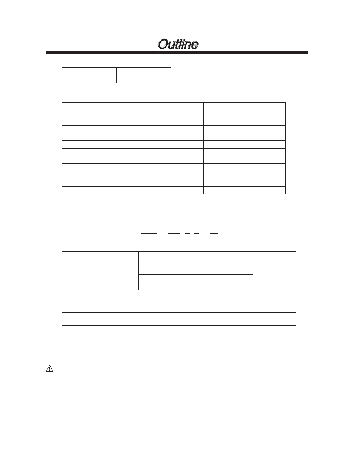
(6) Power code
P with a plug
No symbol without a plug
(7) Controller E : E type
(8) Connection
Codes Applicable hose dia. (ID × OD) Type
4 ø8 × ø13 (mm) VC, V6, PC, VM
5 ø9 × ø12 (mm) VC, V6, PC, VM
6ø10 × ø12 (mm) FC
8 ø3/8" × ø1/2" (inch) VC, V6, PC, VM, FC
9Rc 1/4" SH
10 NPT 1/4" SH
11 ø10 × ø16 (mm) VC, V6, PC, VM
14 Rc 3/8" SH
15 NPT 3/8" SH
21 IN ø15 × ø22, OUT ø9 × ø12 (mm) HP6
22 IN ø15 × ø22, OUT ø3/8" × ø1/2" (inch) HP6
(9) Special configuration
01-99: Special material, special connection port diameter, etc.
• Controller identification
EHC - 100 P E - * *
(1) (2) (3) (4) (5)
(1) Controll er nam e EH
(2) Voltage codes
10 0 100VAC 90-126VAC
50/60Hz
11 U 110 /115 VAC 90 -126VAC
20 J 200VAC 180-220VAC
20 E 220/230/240VAC 198-264VAC
23 U 230VAC 207-253VAC
(3) Lead wire
P: with a plug
No code: without a plug
(4) Controller E
(5) Special configuration
0-99
HV: High viscosity type
Points to be noted in handling
1. Do not detach the control unit unless unavoidable.
2. Never use the control unit with pumps having different symbols for driving unit and power source voltage
specified on the control unit. (Check the nameplate.)
CAUTION
Operation with a pump having different symbols for driving unit and power source voltage other than
those specified may cause failure or trouble in the electronic circuit of the control unit or the driving
unit of the pump.
Outline

-
9 -
Driving unit
●Electromagnet and spring force makes diaphragm
reciprocate responding to the command of control
unit.
Pump body
●Reciprocating movement of diaphragm changes
the volume of pump chamber to make pumping.
Control unit
●The control part to operate pump stop/start,
adjustment of flow rate and stroke speed.
Stroke length adjusting knob
●To adjust discharge capacity per stroke in the
range of 20 to 100%.
● Control unit
Pump operation is done electronically by control unit in which microcomputer is built-in.
● Easy operation
Pump operation and flow rate control is done by keys on control unit, which enables simple control of flow
rate.
● Memory back-up function
If power is turned off, memory back-up function puts the set value in memory. When the power is turned
on again, pump operates at the value which had been set before the power was turned off.
Outline
4. Features
-
10
-
5. Spe cification
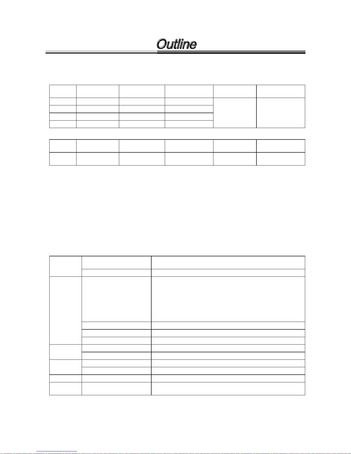
• Pump specification
Standard types
Model
Output capacity
(ml/min)
Output per stroke
(ml/stroke)
Maximum pressure
(MPa)
Stroke frequency
(spm)
Permissible stroke
length % (mm)
31 340 0.19- 0.9 4 1
0-360
20-100
(0.3-1.5mm)
36 520 0.29-1.44 0.7 (0.6)
46 750 0.42-2.08 0.4
56 1250 0.69-3.47 0.2
High viscosity type
Model
Output capacity
(ml/min)
Output per stroke
(ml/stroke)
Maximum pressure
(MPa)
Stroke frequency
(spm)
Permissible stroke
length % (mm)
36 300 0.25-1.25 0.7 0-240
20-100
(0.3-1.5mm)
NOTE 1. The performance data is based on clean water at 25 deg. C under rated voltage.
NOTE 2. Capacity is that at the max. pressure. (at max. stroke length and max. stroke frequency)
Capacity exceeds the value when pump operates under low pressure.
NOTE 3. Operating ambient temperature : 0 to 40 deg. C
Relative humidity : 35 % to 85 % (Non condensing)
NOTE 4. Liquid temperature : 0 to 40 deg. C (PC/SH/FC/HP6 : 0 to 60 deg. C)
NOTE 5. Permissible voltage fluctuation : Within ±10 % of rating
NOTE 6. Ask us for liquid containing slurries or so.
NOTE 7. Value in ( ) of Maximum pressure is the value for type SH.
NOTE 8. Adjustment range of stroke length for EH-E46, 56SH is 50-100% (0.75-1.5mm).
• Control unit specification
Mode
Mode
MAN (Manual)
EXT (External)
Changeover Entering by keys (EXT, START/STOP)
Function
Parameters
EXT :
Digital input pulse multiply 1 : n n = 1 - 999
Digital input pulse dividing n : 1 n = 999 - 1
Analog input SET point1 : Current 0 - 20 mA
Stroke rate 0 - 360 spm
SET point2 : Current 0 - 20 mA
Stroke rate 0 - 360 spm
MAN : Stroke rate 1 - 360 spm
Keys 4 keys (START/STOP, EXT, ▲, ▼)
Upper limited spm 360 spm
Stop By receiving stop signal from outside
Indication
Display 4 digit LCD Operating condition, set value etc.
Stroke Green LED (Blinks synchronous with stroke.)
Input
Stop signal Potential free or open collector (NOTE 2)
Pulse (NOTE1) Potential free or open collector (NOTE 2)
Output Power source for sensor 12VDC 10mA or below
Power
source
100 AC : 90 - 127VAC 110/115AC : 90 - 127VAC
200 AC : 180 - 242VAC 230AC : 198 - 264 VAC
NOTE 1. Max. frequency of input pulse : 100Hz
NOTE 2. Max. applied voltage and amperage to open collector : 5V, 1.1 mA
NOTE 3. Max. spm of the high viscosity type : 240spm
Outline

-
11
-
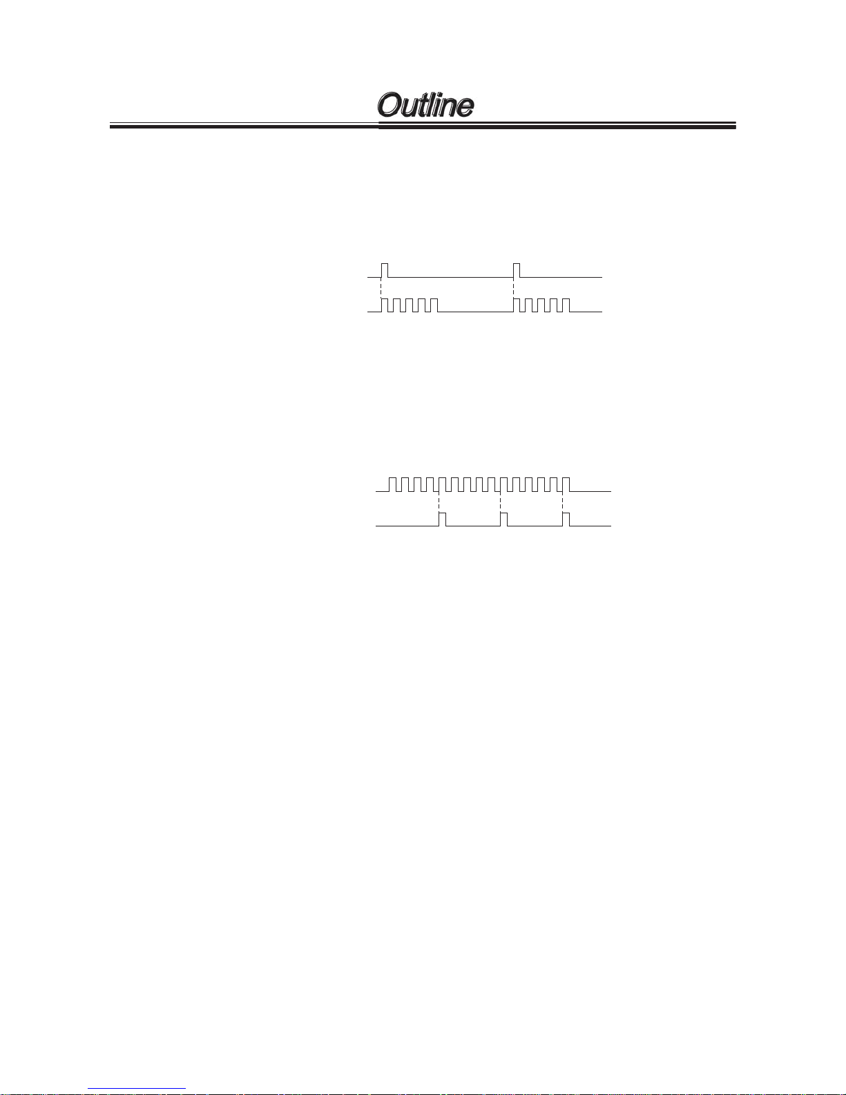
run
stop
run
ON
ON
ON
Operation chart
START/STOP key
Operation
• Analog input operation (0 - 20 mA)
0 - 360 spm operation in proportion to 0 - 20 mA current input. Pump is fixed at 360 spm when came the
input signal exceeding 360 spm.
Straight line is automatically made by setting two points. So, the pump may not come to 0 spm even if 0 mA
current comes.
Straight line is drawn automatically by setting two points.
0 mA is not always 0 spm. It depends on set point. It is possible that 0 mA or 20 mA does not make 0 spm
or 20 mA respectively because of the error of electronics parts. In this case adjust it by setting value.
0A
1
SET point 1
Current
A
2
SET point 2
Current
20 mA
360 spm
SET point 2 spm
SET point 1 spm
6. Operating Function
• Manual operation
Stroke rate can be set from 0 to 360 spm with keys ▲ and ▼, and pump start and stop can be done with
keys START/STOP. Both setting can be done while the pump stops or operates.
Outline
-
12
-
• Digital input (pulse multiply) operation
Pump makes strokes from 1 to 999 responding to external pulse signal. Stroke rate is the spm set for man-
ual operation. The pulses which came while operation are put in memory up to 255 pulses. (It is possible to
make the pulses not to be put in memory.)
Digital input (multiplying) example (× 5)
Pump stroke
Ext. pulse
12345 12345
• Digital input (pulse dividing) operation
Pulse dividing operation by external pulse signals for 999 : 1 to 1 : 1. Stroke rate is the one set for manual
operation. When the signals exceeding the set stroke rate came, excessive signals can be put in memory
up to 255 pulses.
Digital input (Dividing) is set at 5 = /5
External pulse
Pump stroke
123451234512345
Outline
-
13
-
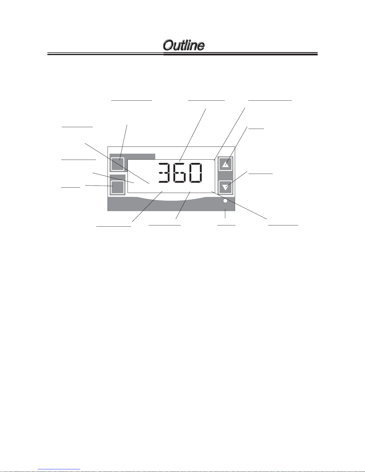
EXT
START/STOP
EH-E
ON
WAIT
EXT
STOP
OVER
SET
Numeric display
1
2
STOP indicator
Over indicator
EXT indicator
WAIT indicator
START/STOP key
ON light
EXT key
SET indicator
DOWN key
UP key
Lit when pump is
operated by external
input.
Lit when pump is in
WAIT mode and
stops.
Set value is shown.
Lit when pump is
stopped by external
stop signal. Pump
stops when lit.
Lit when signal exceeding
360 spm comes in EXT
mode.
To increase set value or to
change setting.
To move to mode for toggling
between analog and digital
by two keys pushing (UP key
and EXT key).
SET point indicator
Lit when SET point 1 and 2
are set at EXT mode analog
input operation.
To decrease set value or to
change setting.
To move to mode to toggle
between analog and digital
by pushing two keys (DOWN
key and EXT key).
Lit when toggling
between analog and
digital also when
external setting mode.
Push to start
pump for external
input operation.
Also used for two
keys pushing.
Manually starts or stops
pump.
Also used to enter set value
and to move to wait mode.
Lit when power is
on and blinks per
stroke.
NOTE: Two keys pushing means to push simultaneously two keys of EXT key and UP or DOWN key.
Outline
7. Displa y a nd Key s
• Controller display and panel
-
14
-
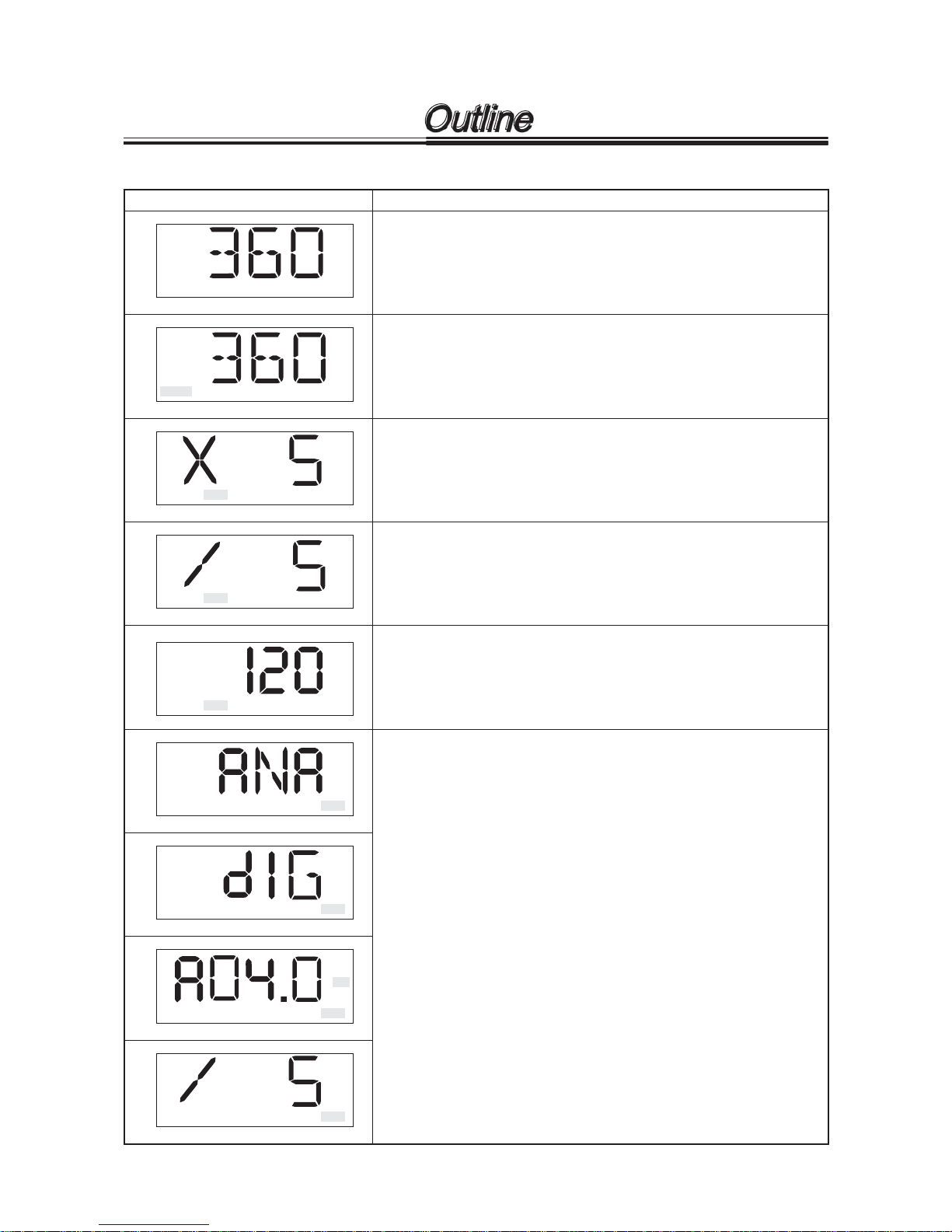
Display examples Meanings
Running at manual operation mode.
Value shows set spm.
WAIT EXT STOP OVER SET
1
2
EXT STOP OVER SET
1
2
WAIT
EXT STOP OVER SET
1
2
WAIT
EXT STOP OVER SET
1
2
WAIT
Waiting at WAIT mode.
Displayed value is set value at manual operation mode.
EXT STOP OVER SET
1
2
WAIT
Running at EXT operation mode (Pulse multiply).
Display shows running at 1 : 5 multiply.
EXT STOP OVER SET
1
2
WAIT
Running at EXT operation mode (Dividing).
Display shows running at 5 : 1 dividing.
EXT STOP OVER SET
1
2
WAIT
Running at EXT operation mode (Analog input 0 - 20 mA).
Display shows running at 120 spm speed responding to input current.
EXT STOP OVER SET
1
2
WAIT
In setting mode. (SET lights.)
EXT STOP OVER SET
1
2
WAIT
• Basic display
Outline
-
15
-
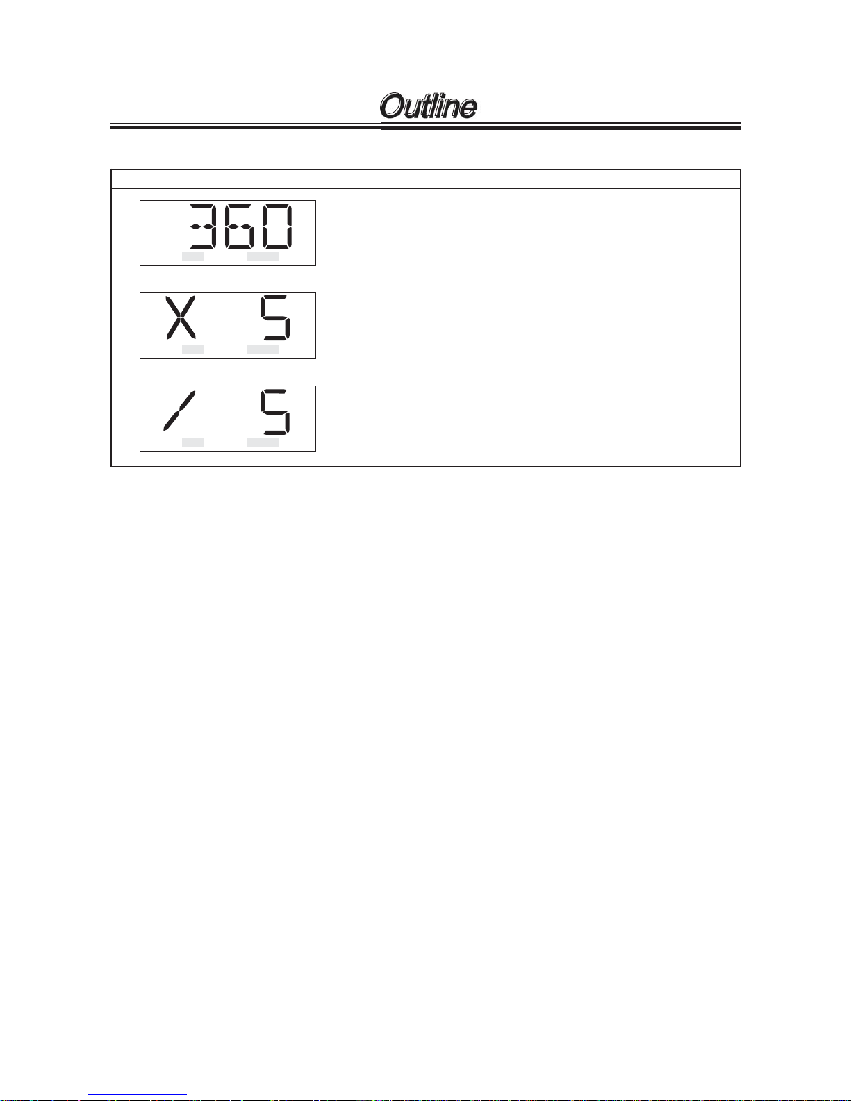
• Alarm display
Display examples Meanings
Display for excess spm at EXT operation (analog input operation). (OVER
lights.)
In analog input operation, visible if external signal exceeding 360 spm operation comes. While visible, pump runs at fixed speed of 360 spm.
Display for excess spm at EXT operation (Pulse multiply operation). (OVER
lights.)
In multiply operation, visible if next pulse comes when the pump is making
the strokes. While visible, max. 255 pulses can be put in storage. You can
set not to put them in storage.
Display for excess spm at EXT operation (Pulse dividing operation). (OVER
lights.)
In dividing operation, visible if signal which exceeds max. preset number
of strokes comes. While visible, the pump runs at fixed max. number of
strokes. You can set so that excessive input pulses can be put in storage up
to 255 pulses.
EXT STOP OVER SET
1
2
WAIT
EXT STOP OVER SET
1
2
WAIT
EXT STOP OVER SET
1
2
WAIT
Outline

-
16
-
1. Notes on Installation
.........................
17
2. Installation
........................................
19
3. Tubing
...............................................
20
4. Electrical Wiring
................................
23
Installation
-
17
-
1. Notes on Operation
Operators and maintenance service staff must read the instruction manual thoroughly before using the prod-
ucts. Do not operate the pump system unless all of the contents in the manual are completely understood.
CAUTION
•
Turn off the power supply
Working without disconnecting the power supply may cause an electrical shock.
Before engaging upon any working procedures involving the pump, make sure to turn
the power supply switch off and to stop the pump and other related devices.
•
Terminate operation
When you detect or become aware of a dangerous sign or abnormal condition during
operation, terminate the operation immediately and start it from the beginning again.
•
Specified power only
Do not operate the pump on voltage, which is not specified on the name plate.
Failure to do so may result in damage or fire. Only the specified power level is to be applied.
•
Keep from heat or flame
Do not place any dangerous materials or flammable objects near the pump for the prevention of fire or accident.
•
Damaged pump
Never operate a damaged pump. A damaged pump may cause leakage or electrical shock.
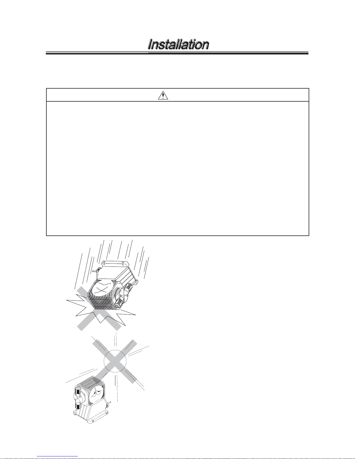
1. Dropping the pump or subjecting it to strong
impacts may result in faulty performance.
Handle the pump with care.
2. When installing the pump, avoid places exposed
to direct sunlight or direct rain with an ambient
temperature of above 40°C, or with a relative
humidity or above 90 %. Though the pump has
a simple waterproof and dust proof structure, a
sheltered location is recommended.
Installation
-
18
-
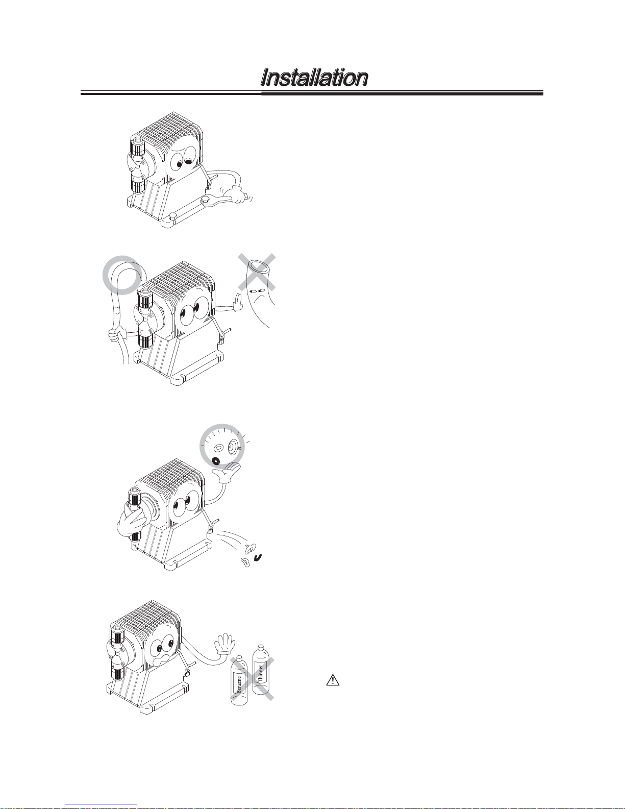
3. Install the pump at the place convenient for the
maintenance/inspection works in the future.
Securely fix the pump so that the pump can not
vibrate horizontally.
4. Use the tube corresponding to the pump suction
and discharge port sizes. Securely connect the
tube so that liquid can not leak or air can not be
sucked in.
5. Make bleeding when you use the pump for the
first time or when you replaced the chemical
tank.
Refer to item "Bleeding procedure" on page 28.
6. When you disassemble the pump head, replace
diaphragm, O ring, valve gasket and valve unit
by new ones.
7. Do not wipe the pump body with the cloth in
which is soaked by solvent such as benzene,
kerosene or thinner. Otherwise, the body may be
discoloured. To clean pump body, use dry cloth
or the cloth in which are soaked by water or neu-
tral detergent.
CAUTION
Liquid splash on driving unit and control
unit may cause failure or accident. Pay
attention the liquid not to be splashed.
Installation
 Loading...