

IWAKI EH-E Instruction Manual
IWAKI
Electromagnetic Metering Pump
Instruction Manual
EH-E Type
Read this manual before use of product

Thank you for choosing an Iwaki’s EH-E Series metering pump. This instruction manual deals with
the correct installation, operation, maintenance, and troubleshooting procedures for the EH-E model
metering pump. Please read through it carefully to ensure the optimum performance, safety and
service of your pump.
Contents
IMPORTANT INSTRUCTION ------------------------------------------1
Safety Section ------------------------------------------2
1.INTRODUCTION ------------------------------------------5
1. Unpacking ------------------------------------------6
2. Operation Principle ------------------------------------------6
3. Specifications ------------------------------------------7
4. Dimensions ----------------------------------------10
2.INSTALLATION ----------------------------------------14
1.
Before Use ----------------------------------------15
2.
Location ----------------------------------------16
3.
Supply Tubing ----------------------------------------16
4.
Discharge Tubing ----------------------------------------17
5.
Electrical ----------------------------------------17
3.OPERATION ----------------------------------------18
1.Priming ----------------------------------------19
2.
Adjustment ----------------------------------------20
3.
Calibration ----------------------------------------20
4.
External Control
4,1Display/Keypad and Wiring Overview -----------------------------21
4,2 Quick Reference ----------------------------------------22
4,3 Digital Mode ----------------------------------------25
4,4 Analog Mode / STOP Function ---------------------------------------26
4,5 AC Power Inte rruption ----------------------------------------28
5.MAINTENANCE ----------------------------------------29
1.
Maintenance ----------------------------------------30
2.
Diaphragm Replacement ----------------------------------------30
3.
Valve Replaceme nt ----------------------------------------30
4.
Tubing ----------------------------------------30
5.
Names of Part and Structure ----------------------------------------31
6.
Troubleshooting ----------------------------------------35
1.Troubleshooting ----------------------------------------36

Important Instruction
For the Safe and Correct Handling of the Pump
Read the "Safety Instructions" sections car efully to prevent accidents involving your customers
or other personnel and to avoid damage or loss of other assets. Always follow the inst ructions
and advice found in these sections.
Observe and abide by the instructions described in this manual.These instructions are very
important for protect ing pum p users fr om dang erous conditions and sit uations related with t he
use of the pump system.
The symbols relate to the following meanings descr ibed below.
Warning.
Nonobservance or misapplication of the contents of the
"Warning" section could lead to a serious accident,including
death or injury.
Caution.
Nonobservance or misapplication of the contents of the
"Caution" section could lead to serious physical injury to the
user or serious damage to the product.
Types of Symbols
Indicates that "Warning" or "Caution" must be exercised. Inside this triangle, a
concrete and practical image provided as a warning or caution message is
depicted.
Indicates a prohibited action or procedure.Inside or near t his cir c le, a concret e
and practical image of the activity to be avoided is depicted.
Indicates an important action or procedure which must be performed or carried
out without fail. Failure to follow the inst r uct ions herein can lead to malfunction
or damage to the pump.
- 1 -
Safety Section
Warning.
Turn off the power supply
Working without disconnecting the power supply cause an electrical shock.
Before engaging upon any working procedures involving the pump ,
make sure
to turn the power supply switch off and to stop the pump and other related
devices.
Electrical shock
Terminate operation!
!!
!
When you detect or become aware of a dangerous sign or abnormal condition
during operation , terminate the operation immediately and start from the
beginning again.
For specified application only.
..
.
The use of a pump in any application other than those clearly specified may
result in injury or damage to the pump . Use the pump strictly in accordance with
the pump specifications and application range .
Prohibited
No remodeling !
!!
!
Never remodel a pump .Otherwise ,a serious accident may result.Iwaki will not
be responsible for any accident or damage of any kind which is caused by the
user remodeling the pump without f irst obtaining permission or inst ructions from
lwaki .
No remodeling
Wear protectors.
..
.
If you touch or come in contact with any type of hazardous chemical liquid ,
including but not limited to chemicals, you may experience a serious injury. Wear
protective gear (protective mask, g loves , etc.)during the pump operation.
Wear protective
gear
Operating site must be free of water and humidi t y .
The pump is not designed to be water-proof or dust-proof . The use of the
pump in places where water splashes or humidity is high may result in an
electrical shock or short circuit.
Prohibited
- 2 -
Safety Section
Caution.
Qualified operators only!
!!
!
The pump operator and pump operation supervisor must not allow any operators
who have little or no knowledge of the pump to run and operate the pump . Pum p
operators must have a sound knowledge of the pump and it s oper ation.
Prohibited
Specified power only.
..
.
Do not operate the pump on voltage which is not specified on the nameplate.
Failure to do so may result in damage or fire . Only the specif ied power level is to
be applied.
Prohibited
Do not run the pump dry.
..
.
Do not run the pump dry (without liquid inside the pump).Heat generated as a
result of abrasion between elements inside the pump during operation without
liquid may damage the inside of the pum p.
Prohibited
Do not wet or dampen!
!!
!
If an electric part or wiring get s wet with the liq uid spilled over accident ally , a f ire
or electrical shock may be caused . Install the system in a place f ree from liq uid
spillage or leakage .
Do not wet or
dampen
Ventilate!
!!
!
Poisoning may result during an oper ation which involves, toxic or odorous liquid.
Ventilate the operating site sufficiently.
Caution
Spill-out accident!
!!
!
Protective measures should be taken against any accidental spill-out or leakage
of the operating liquid as a result of unexpected damage on the pump or the
related piping.
Caution
Damaged pump
Never operate a damaged pump. A damaged pump may cause leakage or
electrical shock.
Prohibited
Do not damage or change power cable !
Do not scratch, damage ,process, or pull the power cable forcibly. An extra load
onto the cable ,such as heating the cable or placing something heavy on the
cable ,may damage the cable and finally cause a fire or an elect r ical shock.
Caution
- 3 -
Safety Section
Caution.
Arrange grounding!
!!
!
Do not operate the pump without connecting the gr ounding wire. Otherwise, an
electrical shock may result . Make sure the grounding wire is connected with
grounding terminal.
Grounding
Install an earth leakage breaker (option)!
!!
!
The operation of a pump without using an earth leak age breaker may cause an
electrical shock . Please purchase an optional leak age breaker and inst all in the
system.
Electrical
Shock
Handling of power cable
Use of a defective or damaged power cable may result in a fire or electrical
shock.Handle the power cable carefully.
Electrical
Shock
Follow the instruction manual
Replace the consumable part by following the descriptions in the instruction
manual .Do not disassemble any part of the pump if the disassembling procedure
for the part in question is not included in t he instruction manual.
Limited operating site and storage
Do not install or store the pump in the following places:
Places where a flammable gas or material is used or stor ed.
Places where the ambient temperature is extremely high(40℃ or higher)or
extremely low (0℃ or lower).
Prohibited
Disposal of used pump
Disposal of used or damaged pumps must be done in accordance with the
relevant local law and regulations .(Consult a licensed industrial waste products
disposing company.)
- 4 -

1.INTRODUCTION
1. Unpacking -----------------------------6
2. Operation Principle ------------------6
3. Specifications--------------------------7
4. Specifications of Control Unit------9
5. Dimensions---------------------------10
- 5 -
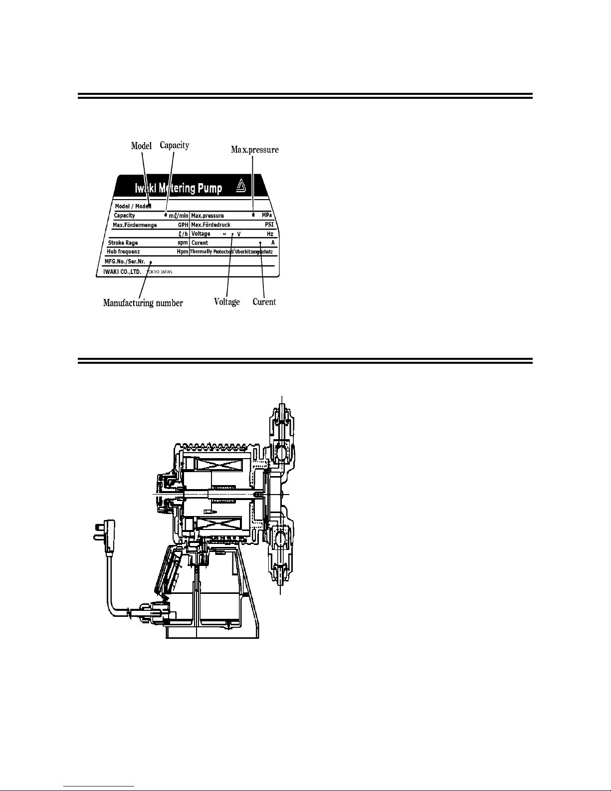
1.Unpacking
After unpacking the goods, check the following points
to ascertain that the product is exactly as you ordered.
If you find anything wrong, please get in touch with
your dealer.
(1) Do the model, voltage, etc., shown on the nameplate
represent what you ordered?
(2) Has the goods been damaged in transit? Are the
bolts and nuts loose?
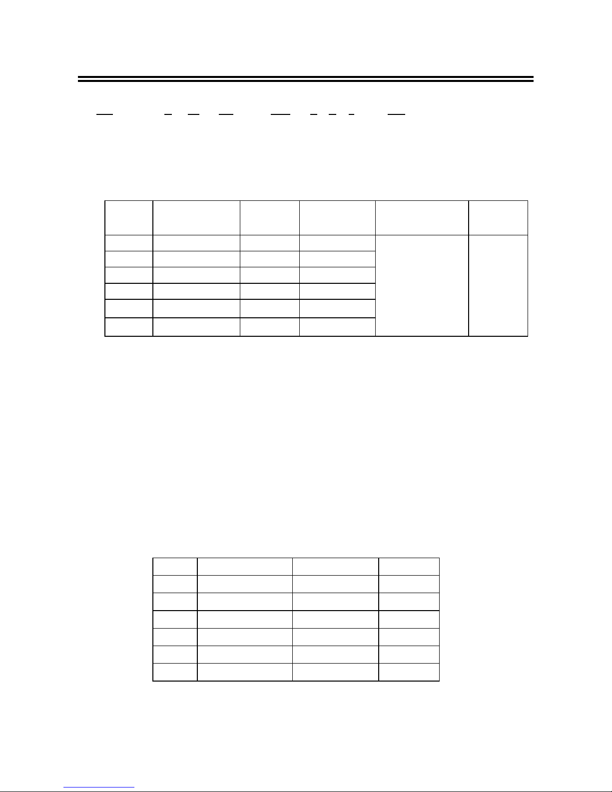
2.Operation Principle
The EH Series electronic metering pump consists of a
pump unit, a drive unit, and a control unit. The drive
unit is an electromagnetic solenoid. When the
solenoid coil is energized by the control unit the
armature shaft moves forward due to the magnetic
force of the solenoid. The shaft is attached to a PTFE
faced diaphragm which is part of the pump unit. The
diaphragm is forced into the pump head cavity
decreasing volume and increasing pressure which
forces liquid in the pump head out though the
discharge check valves. When the solenoid coil is deenergized, a spring returns the armature to its starting
position. This action pulls the diaphragm out of the
head cavity increasing volume and decreasing
pressure. Atmospheric pressure then pushes liquid
from the supply tank through the suction check valves
to refill the pump head.
- 6 -
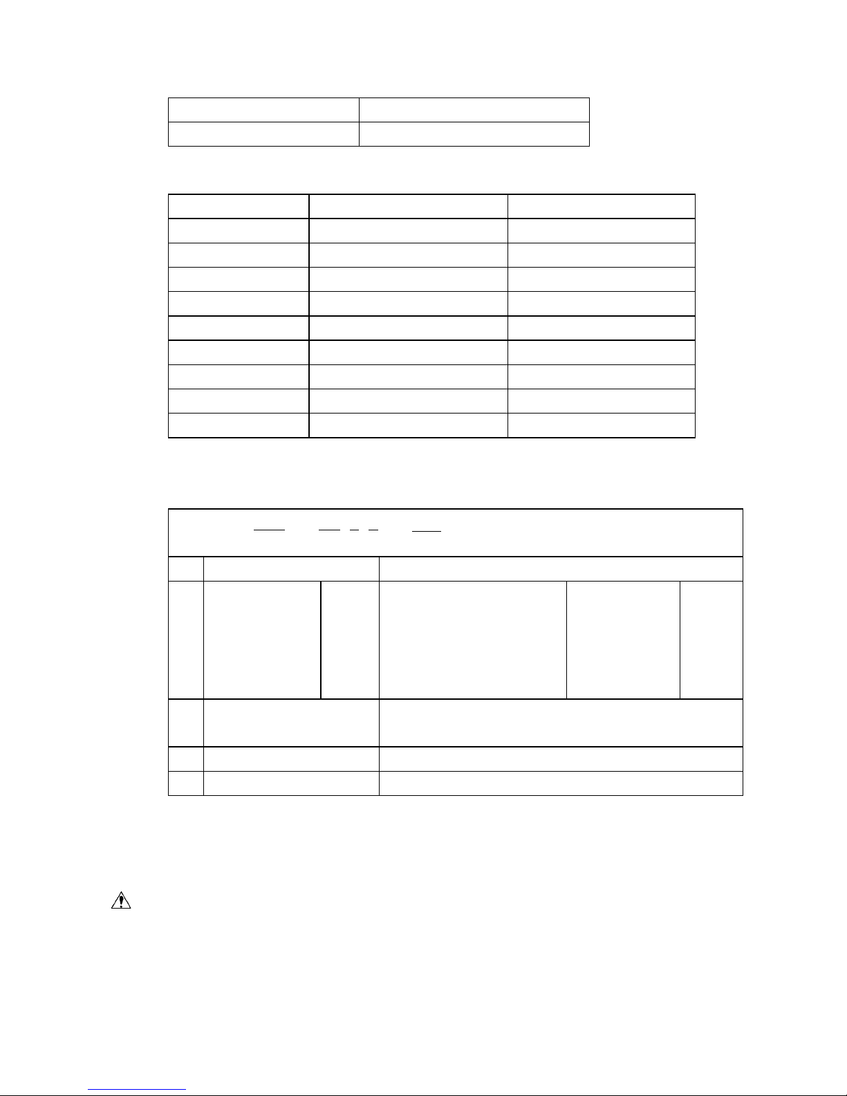
3.Specifications
Pump identification
EH -E30 PC - 23U P E 8 -
①②③④⑤⑥⑦⑧⑨
① Series name EH Series
② Drive component E : 48 W
③ Diaphragm effective diameter 30:30mm 35:35mm 45:45mm 55:55mm
④ Material of liquid end
Symbol Pump head
& Fittings
Valve Balls Valve seat &
O-ring(Gasket)
Diaphragm Gasket
VC PVC CE FKM
V6 PVC SUS316 EPDM
PC GFRPP CE FKM
VM M-PVC CE FKM
FC PVDF CE PCTFE(PTFE)
SH SUS316 HC276 SUS316(PTFE)
PTFE
(bonded to EPDM)
PTFE
PVC : Polyvinyl chloride (Transparent)
GFRPP : Glass fiber reinforced polypropylene
M-PVC : Polyvinyl chloride (Machined)
CE : Alumina ceramics
SUS316 : 316 Stainless steel
FKM : Fluoroelastomer
EPDM : Ethylene propylene diene methylene
PTFE : Polytetrafluoroethylene
PVDF : Pplyvinylidenefluoride
HC276 : Hastelloy C276
⑤ Voltage symbol
Symbol Voltage Input voltage Frequency
100 AC100V
AC 90 ~ 110V
50-60 Hz
11U AC 110V, 115V
AC 90 ~ 126V
50-60 Hz
20J AC 200V
AC 180 ~ 220V
50-60 Hz
23U AC 230V
AC 207 ~ 253V
50-60 Hz
20E AC 220,230,240V
AC 198 ~ 264V
50-60 Hz
20E AC 220,230,240V
AC 198 ~ 264V
50-60 Hz
- 7 -
⑥ Power code
P with plug
No symbol without plug
⑦ Controller E : E type
⑧ Connection
Symbol
Applicable hose dia. (ID×OD)
Type
4
φ 8 × φ 13 (mm)
VC,V6,PC,VM
5
φ 9 × φ 12 (mm)
VC,V6,PC,VM
6
φ 10 × φ 12(mm)
FC
8
φ 1/2” × φ 3/8”(inch)
VC,V6,PC,VM,FC
9 Rc 1/4” SH
10 NPT 1/4” SH
11
φ 10 × φ 16(mm)
VC,V6,PC,VM
14 Rc 3/8” SH
15 NPT 3/8” SH
⑨ Special configuration
01~99: Special material , special connection port diameter , etc.
Controller identification
EHC - 100
P E
- **
****
**
① ② ③④ ⑤
①
Controller name EH
②
Voltage symbol
10 0
11 U
20 J
20 E
23 U
AC100V
AC110V,AC115V
AC200V
AC220V,AC230V,AC240V
AC230V
AC 90 ~126V
AC 90 ~ 126V
AC180 ~ 220V
AC198 ~ 264V
AC207 ~ 253V
50-60
Hz
③
Lead wire
P: with plug
No symbol: without plug
④
Controller E
⑤
Special configuration 0 ~ 99
Points to be noted in handling
1.Do not detach the control unit unless unavoidable.
2.Never use the control unit with pumps having different symbols for driving unit and power source
voltage specified on the control unit. (Check the nameplate.)
Caution
Operation with a pump having different symbols for driving unit and power source voltage other than
those specified may cause failure or trouble in the electronic circuit of the control unit or the driving
unit of the pump.
- 8 -

Pump specifications
Model
Output
capacity
(ml/min)
Output per
Stroke
(ml/stroke)
Maximum
Pressure
(MPa)
Stroke
frequency (spm)
Stroke
length %
(mm)
30 340
0.19~0.94
1
35(SH) 520
0.29~1.44
0.7(0.6)
45 750
0.42~2.08
0.4
E
55 1250
0.69~3.47
0.2
0~360
20~100
(0.3~1.5mm)
Note 1.
The performance data is based on clean water at 25℃ under rated voltage.
Note 2.
Capacity is that at the max. pressure.(at max.stroke length and max.stroke frequency)
Capacity exceeds the value at max.pressure w hen pump operates under low
pressure.
Note 3.
Operating ambient temperature : 0 ~ 40
℃
Relative humidity : 30% to 90% non-condensing
Note 4.
Liquid temperature : PVC/PVDF 0℃ ~ 40℃ (PC/SH : 0℃ ~ 60℃)
Note 5.
Permissible voltage fluctuation : Within ±10% of rating
*Please note that for the purpose of improvement,parts which have no effect on specif ications
and fitting sizes are subject to change without pr ior not ice.
*For SH type, install air chamber of approx. 500 ml volume at the location as close to pump
discharge port.
Adjustment Range Recommended stroke length adjustment range 20% to 100%
Recommended frequency adjustment range 0 to 360 stroke per minute
Control unit specifications
Control
function
Selection of Function.
The function is selected
with the operation key.
MAN : Manual control
EXT : External signal control
(EXT,START/STOP)
EXT
Digital input dividing
Digital input counter
1 : n , n=1~999
n : 1 , n=999~1
Setting
Analog input
Analog input
MAN
DC 4~20 mA ,DC 0~20 mA
DC 20~4 mA ,DC 20~0 mA
Stroke rate 0~360spm
Setting method Operation 4keys START/STOP,EXT,
Max spm Fixed at stroke rate of 360 spm
Control
Stop(Input stop) Stopped when contact signal is input.
Data LCD,4-digit,State of drive,Set value etc.,Display
Pump operation Green LED(Flashes in sync with pump stroke)
Pules input No-voltage contactInput signal
Stop input No-voltage contact
Output Sensor power DC 12V , 10mA
Power supply
AC 100 : AC 90 ~ 110 V , AC110V・・・・ AC115V:AC 90 ~ 127V
AC 200 : AC 180 ~242 V , AC 230 : AC198 ~264 V
- 9 -
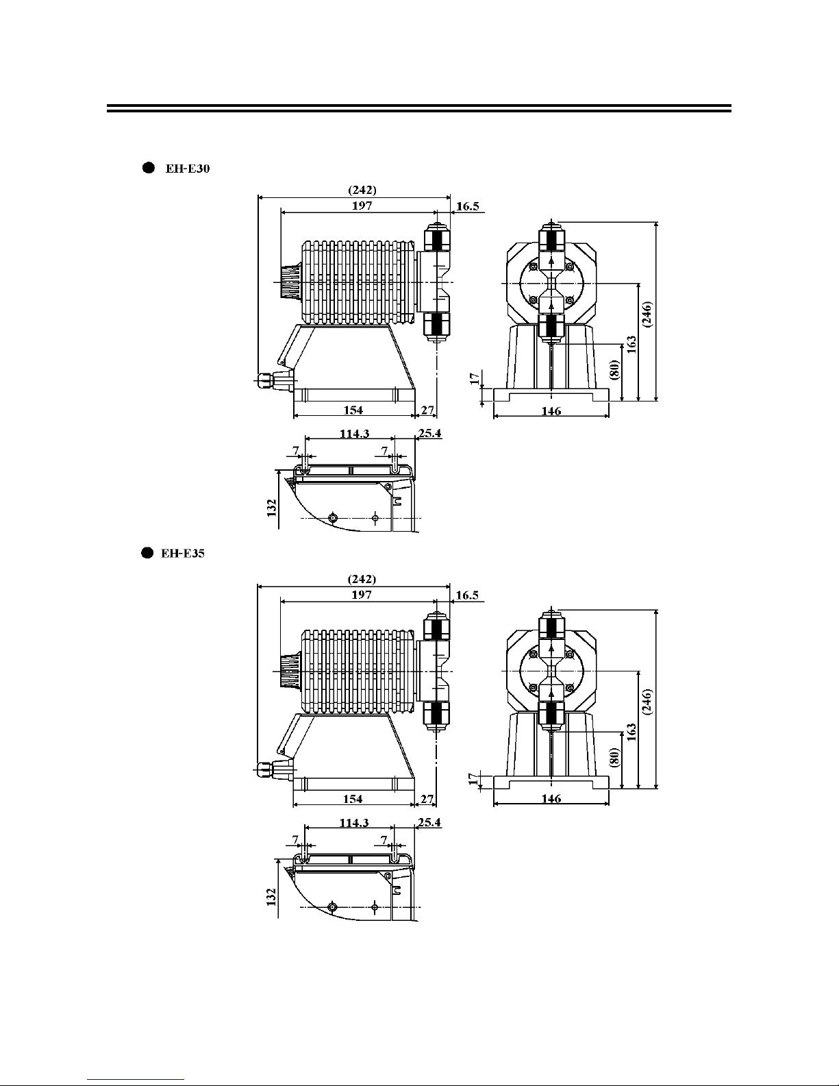
5. Dimensions (
Material symbol: VC/V6/PC/VM/FC
)
- 10 -
 Loading...