

Ivy Biomedical Systems 7600, 7800 Operation Manual

Part No. 2718-55-16
OPERATION MANUAL
© 2017 IVY Biomedical Systems Inc. All Rights Reserved.
Part No. 3232-00-16 Rev.12 EN
Cardiac Trigger Monitor
Model 7600/7800
Model 7800 shown

TABLE OF CONTENTS
TABLE OF CONTENTS
1.0 USER RESPONSIBILITY .......................................................................................................................... 1
2.0 MANUAL REVISION HISTORY .............................................................................................................. 2
3.0 WARRANTY ................................................................................................................................................ 3
4.0 INTRODUCTION ........................................................................................................................................ 4
5.0 SAFETY ........................................................................................................................................................ 5
5.1 Electrical ......................................................................................................................................... 5
5.2 Explosion ......................................................................................................................................... 6
5.3 Patient Connections ........................................................................................................................ 6
5.4 MRI .................................................................................................................................................. 7
5.5 Pacemakers ..................................................................................................................................... 7
5.6 Electrosurgery Protection .............................................................................................................. 7
5.7 Defibrillation Protection ................................................................................................................ 7
5.8 Signal Amplitude ............................................................................................................................ 7
5.9 EMC ................................................................................................................................................ 7
5.10 Accessories ...................................................................................................................................... 8
5.11 Description of Symbols Used ....................................................................................................... 11
6.0 MONITOR DESCRIPTION ...................................................................................................................... 12
6.1 Intended Use ................................................................................................................................. 13
6.2 Patient Population ........................................................................................................................ 13
6.3 Contraindications ......................................................................................................................... 13
6.4 Classification (in accordance with ANSI/AAMI ES60601-1:2005) .......................................... 13
6.5 Controls and Indicators ............................................................................................................... 14
6.6 Display ........................................................................................................................................... 15
6.7 Alarm Messages ............................................................................................................................ 15
6.8 Programmable Touch Keys ......................................................................................................... 15
6.9 Menu Structure............................................................................................................................. 16
6.10 Rear Panel ..................................................................................................................................... 17
6.11 Fuse Ratings .................................................................................................................................. 17
6.12 Rear Panel Description ................................................................................................................ 18
7.0 MONITOR SE TUP .................................................................................................................................... 19
7.1 Monitor Installation ..................................................................................................................... 19
7.2 To Set Up the Instrument for Operation .................................................................................... 19
7.3 Setting the Date and Time ........................................................................................................... 20
7.4 Setting the QRS and Alarm Volume ........................................................................................... 20
7.5 Setting the Alarm Limits.............................................................................................................. 20
7.6 Setting the Trace Speed ............................................................................................................... 20
7.7 Default Settings ............................................................................................................................. 21
8.0 SYNCHRONIZED OUTPUT (TRIGGER) .............................................................................................. 22
8.1 The Synch Pulse ............................................................................................................................ 22
8.2 Trigger Mark ................................................................................................................................ 22
8.3 Polarity Lock (P-Lock) ................................................................................................................ 22
Model 7600/7800 Operation Manual i

TABLE OF CONTENTS
9.0 ECG MON ITORING ................................................................................................................................. 23
9.1 Safety Considerations ................................................................................................................... 23
9.2 Patient Connections ...................................................................................................................... 24
9.3 ECG Electrodes ............................................................................................................................ 25
9.4 Impedance Measurement (Model 7800 Only) ............................................................................ 26
9.5 ECG Waveform Amplitude (Size)............................................................................................... 27
9.6 ECG Notch Filter.......................................................................................................................... 27
9.7 Lead Selection ............................................................................................................................... 28
9.8 Low Signal Message ..................................................................................................................... 29
9.9 Pacemaker ..................................................................................................................................... 29
9.10 Alarm Limits ................................................................................................................................. 30
10.0 SYSTEM INTERLOCK OPERATION ................................................................................................. 31
10.1 X-Ray Status Messages (Model 7800 Only)................................................................................ 31
11.0 ECG DATA STORAGE AND TRANSFER ........................................................................................... 32
11.1 ECG Data Transfer Using the USB Port (Model 7800 Only) ................................................... 32
11.2 USB Port........................................................................................................................................ 32
12.0 RECORDER OPERATION ................................................................................................................... 33
12.1 Changing Paper ............................................................................................................................ 33
12.2 Recorder Modes ............................................................................................................................ 34
12.3 Recorder Speed ............................................................................................................................. 35
12.4 Sample Printouts .......................................................................................................................... 35
13.0 ALARM MESSAGES .............................................................................................................................. 36
13.1 Reminder Signals .......................................................................................................................... 36
13.2 Patient Alarms .............................................................................................................................. 36
13.3 Technical Alarms .......................................................................................................................... 37
13.4 Informatory Messages .................................................................................................................. 37
14.0 MONITOR TESTING .............................................................................................................................. 38
14.1 Internal Test .................................................................................................................................. 38
14.2 ECG Simulator ............................................................................................................................. 38
15.0 TROUBLESHOOTING ........................................................................................................................... 40
16.0 MAINTENANCE AND CLEANING ...................................................................................................... 41
16.1 The Monitor .................................................................................................................................. 41
16.2 Patient Cables ............................................................................................................................... 41
16.3 Preventive Maintenan c e ............................................................................................................... 41
17.0 ACCESSORIES ........................................................................................................................................ 42
18.0 DISPOSAL ................................................................................................................................................ 43
18.1 WEEE Directive 2012/19/EU ....................................................................................................... 43
18.2 RoHS Directive 2011/65/EU ......................................................................................................... 43
18.3 Standard of the Electronics Industry of the Peopl e ’s Republic of China SJ/T11363-2006 .... 43
19.0 SPECIFICATIONS .................................................................................................................................. 44
ii Model 7600/7800 Operation Manual
USER RESPONSIBILITY
1.0 USER RESPONSIBILITY
This product will perform in conformity with the description contained in this Operation Manual and accompanying
labels and/or inserts, when assembled, operated, maintained and repaired in accordance with the instructions
provided. This product must be checked periodically. A defective Product should not be used. Parts that are broken,
missing, plainly worn, distorted or contaminated should be replaced immediately. Should such repair or replacement
become necessary, Ivy Biomedical Systems, Inc. recommends that a telephone call or written request for service
advice be made to Ivy Biomedical Systems, Inc.’s Service Department. This product or any of its parts should not be
repaired other than in accordance with instructions provided by Ivy Biomedical Systems, Inc.’s trained personnel.
The product must not be altered without the prior written approval of Ivy Biomedical Systems, Inc.’s Quality
Assurance Department. The user of this Product shall have the sole responsibility for any malfunction which results
from improper use, faulty maintenance, improper repair, damage or alteration by anyone other tha n Ivy Biomedical
Systems, Inc.
CAUTION: US Federal law restricts this device to sale by or on the order of a licensed medical practitioner.
Ivy Biomedical Systems, Inc.
11 Business Park Drive
Branford, Connecticut 06405 USA
(203) 481-4183 (800) 247-4614 FAX (203) 481-8734
www.ivybiomedical.com e-mail: sales@ivybiomedical.com
Model 7600/7800 Operation Manual 1

MANUAL REVISION HISTORY
_____________________________________________________________________________
Revision
Date
Description
00
August 11, 2011
Initial Release of Model 7600 Operation Manual
01
March 13, 2012
Changed title to Model 7600/7800 Operation Manual.
Operation Manual.
02
May 7, 2012
Revised Operation Manual to comply with IEC 60601-1 3rd
edition.
03
June 4, 2012
Added Patient Population and Contraindications statements
to Monitor Description section of the Operation Manual.
04
June 5, 2012
Revised Power/Standby symbol and added IPX1 statement.
05
September 28, 2012
Added warning statement regarding reducing the
of the Operation Manual.
06
January 31, 2013
Increased Operating Environment and Storage
Environment Temperature Range.
07
November 20, 2013
Updated China RoHS table and Warning and Caution
symbols.
08
December 9, 2013
Corrected typographical errors in sections 7.3 and 7.4.
09
March 9, 2015
Updated EMC Guidance and Manufacturer’s Declaration
fuse rating and type to T .5A, 250V.
10
September 2, 2015
Revised all references to fuse rating and type to T 0.5AL,
250V.
11
June 8, 2016
Revised sections 6.10 and 6.12.
12
March 1, 2017
Revised section 19.0 to include additional regulatory
standards.
2.0 MANUAL REVISION HISTORY
Added model 7800 description, specifications etc. to
possibility of a tripping hazard to the Monitor Setup section
on pages 8, 9 and 10. Added EAC symbol to User
Responsibility section on page 1. Updated all references to
WEEE Directive to 2012/19/EU. Revised all references to
2 Model 7600/7800 Operation Manu al

WARRANTY
3.0 WARRANTY
All products manufactured by Ivy Biomedical Systems, Inc. under normal use, are warranted to be free from defects
in material and workmanship and to operate within published specifications, for a period of 13 months from date of
original shipment.
All accessories such as patient cables and lead wires, supplied by Ivy Biomedical Systems, Inc. under normal use,
are warranted to be free from defects in material and workmanship and to operate within published specifications, for
a period of 90 days from date of original shipment.
If an examination by Ivy Biomedical Systems, Inc. discloses such product(s) or component part(s) to have been
defective, then Ivy’s obligation is limited at Ivy’s option, to repair or replacement.
When a product or products need to be returned to the manufacturer for repair or examination, contact service
personnel at Ivy Biomedical Systems to obtain a Return Material Authorization number (RMA #) and the correct
packing instruct ions:
Service / Tech Support:
Telephone: (203) 481-4183 or (800) 247-4614
Fax: (203) 481-8734
E-mail: service@ivybiomedical.com
All products being returned for warranty repair shall be shipped prepaid to:
Ivy Biomedical Systems, Inc
Attn: Service Department
11 Business Park Drive
Branford, CT 06405 USA
Ivy will send the shipment of the repaired or replacement product to customer at Ivy’s expense.
Model 7600/7800 Operation Manual 3

INTRODUCTION
4.0 INTRODUCTION
This manual provides information on the correct use of the Model 7600/7800 Cardiac Trigger monitor. It is up to the
user to ensure that any applicable regulations regarding the installation and operation of the monitor are observed.
The Model 7600/7800 is ME EQUIPMENT (Medical Electrical Equipment) that is intended to monitor patients
under medical supervision. The Model 7600/7800 monitor must be operated by trained and qualified medical
personnel o nly.
Using This Manual
We recommend that you read this manual before operating the equipment. This manual is written to include all
options. If your monitor does not include all options, menu selections and display data for those options will not
appear on your monitor.
Use the Monitor Description section for general descriptions of controls and displays. For details on the use of each
option, refer to the section of the manual dealing with the appropriate option.
Boldface type is used in text to refer to the labeling on user controls. Brackets [ ] surround menu select ions used
with the programmable touch keys.
Manufacturer’s Responsibility
The manufacturer of this equipment is responsible for the effects on safety, reliability, and performance of the
equipment only if:
• Assembly operations, extensions, re-adjustments, or repairs are carried out by persons authorized by the
manufacturer
• The electrical installation complies with all applicable regulations
• The equipment is used in accordance with the instructions in this manual
Incorrect operation or failure of the user to maintain the monitor in accordance with proper maintenance procedures
relieves the manufacturer or his agent from all responsibility for consequent non-compliance, damage, or injury.
Ivy Biomedical Systems, Inc.
11 Business Park Drive
Branford, Connecticut 06405
(203) 481-4183 or (800) 247-4614
Fax (203) 481-8734
E-mail: sales@ivybiomedical.com
This manual expla ins how to set up and use the Model 7600/7800. Importa nt safety information is located
throughout the manual where appropriate. READ THE ENTIRE SAFETY INFORMATION SECTION BEFORE
YOU OPERATE THE MONITOR.
4 Model 7600/7800 Operation Manual

SAFETY
5.0 SAFETY
5.1 Electrical
This product is intended to be operated from a mains power source of 100-120V~ or 200-230V~, 50/60 Hz and a
maximum ac power consumption of 45VA.
protective earth. Connect the monitor only t o a three-wire, grounded, hospital grade receptacle. The three-conductor
plug must be inserted into a properly wired three-wire receptacle; if a three-wire receptacle is not available, a
qualified electrician must install one in accordance with the governing electric code.
defeat this protection by modifying the cable or by using ungrounded adapters or extension cables. The power cord
and plug must be intact and undamaged. To di sconnect the equipment from the mains power; unplug the power
cord.
WARNING: To avoid risk of electric shock, this equipment must only be connected to a supply mains with
WARNING: Do not under any circumstances remove grounding conductor from the power p l ug.
WARNING: The power cable supplied with this equipment provides for this protection. Do not attempt to
WARNING: Do not connect to an electrical outlet controlled by a wall switch or dimmer.
WARNING: If there is any doubt about the integrity of th e protecti ve ground cond uctor arrangement, do not
operate the monitor until the ac power source protective conductor is fully functional.
WARNING: For po wer interrupti ons exceeding 30 seconds, the monitor must be turned on manually by
pressing the Power On/Standby switch. When monitor power is restored, the monitor will return to manufacturer's
DEFAULT settings. (An option is available which will allow monitor to use the last used or STORED settings.)
WARNING: To avoid unacceptable RISK caused by power interruptions, connect the monitor to an
appropriate medical-grade uninterruptable power source (UPS).
WARNING: Do not place the monitor in an y position that may cause it to fall on the patient. Do not lift the
monitor by the power supply cord or patient cable.
WARNING: Carefully route monitor cables (patient cables, power cords, etc.) to reduce the possibility of a
tripping hazard.
WARNING: Do not position the monitor in a way that would cause difficulty to the operator to disconnect it
from the power source.
WARNING: Electric shock hazard! Do not remove covers or panels. Refer service to trained and
qualified service personnel.
Model 7600/7800 Operation Manual 5
SAFETY
WARNING: Disconnec t the moni to r fro m its power source whe n ser vic ed . Refer service to trained and
qualified service personnel.
WARNING: All replaceable parts should be replaced by trained and qualified service personnel.
WARNING: To avoid electrical shock, disconnect the monitor from its power source before changing fuses.
Replace fuse only with same rating and type: T 0.5AL, 250V.
WARNING: Do not clean monitor while it is p lugged into a power source.
WARNING: If unit is accidentally wet, immediately disconnect the monitor from its power source.
Discontinue use until dry and then test unit for proper operation before reuse on a patient.
WARNING: This unit uses a common isolation path for the ECG leads and Electrodes. Do not allow the
ECG leads and/or Electrodes to come in contact with other conductive parts including earth ground. Do not connect
any non-isolated accessories to the ECG input when connected to a patient, as this may compromise the safety of the
unit. When attached to other devices, ensure that the total chassis leakage currents of all units do not exceed 300
μA.
WARNING: The synchr onized output pulse is not designed to synchronize a defibrillator discharge or a
cardioversion procedure.
WARNING: To ensure proper monitor ve ntilation, do not use the monitor witho ut the bottom cover feet or
the optional bottom cover mountin g pla te .
WARNING: Do not modify this equipment without authorization of the manufac turer.
5.2 Explosi on
WARNING: Explosion hazard! Do not use this equipment in the presence of flammable anesthetics or
other flammable substance in combination with air, oxygen-enriched environment or nitrous oxide.
5.3 Patient Connections
Patient connections are electrically isolated. For all connections use isolated probes. Don’t le t patient connections
contact other conductive parts, including earth ground. See inst ructions for patient connections in this man ual.
Carefully route patient cables to reduce the possibility of patient entanglement or strangulatio n.
Leakage current is limited internally by this monitor to less than 10 μA. However, always consider cumulative
leakage current that can be caused by other equipment used on the patient at the same time as this monitor.
To ensure that the leakage current protection remains within the specifications, use only the patient cables specified
in this manual. This monitor is supplied with protected lead wires. Do not use cables and leads with unprotected
6 Model 7600/7800 Operation Manual

SAFETY
lead wires having exposed conductors at the cable end. Unprotected lead wires and cables may pose an
unreasonable risk of adverse health consequences or death.
Line isolation monitor transients may resemble actual cardiac waveforms and thus inhibit heart rate alarms. To
minimize this problem, ensure proper electrode placement and cable arrangement.
If an alarm condition occurs while the alarms are set to off, neither visual no r audio alarms will be present.
5.4 MRI
The Model 7600/7800 should not be used within the magnetic field during M agnetic Resonance Imaging.
5.5 Pacemakers
WARNING – PACEMAKER PATIENTS: Rate meters might continue to count the pacemaker rate during
occurrences of cardiac arrest or some arrhythmias. Do not rely entirely on rate meter ALARM SIGNALS. Keep
pacemaker PATIENTS under close surveillance. See the SPECIFICATIONS section in this manual for disclosure of
the pacemaker pulse rejection cap a bilities of this instrument. AV sequential pacemaker pulse rejection has not been
evaluated; do not rely on pacemaker rejection with patients with dual chamber pacemakers.
5.6 Electrosurgery Protection
This equipment is protected against ele c trosurgery potentials. To avoid the potential of electrosurgery burns at
monitoring sites, ensure proper connection of the electrosurgery return circuit as described by the manufacturer’s
instructions. If improperly connected, so me electrosurgery units might allow energy to return through the ECG
electrodes.
5.7 Defibrillation Protection
This equipment is protected up to 360 J defibrillator discharge. The monitor is internally protected to limit current
through the electrodes to prevent injury to the patient and damage to the equipment as long as the defibrillator is
used in conformance with the manufacturer’s instructions. Use only Ivy specified accessories (see Accessories).
5.8 Signal A mplitude
WARNING: The minimum patient physiological “R-wave” signal amplitude is 0.5 mV.
The use of the Model 7600/7800, below the above amplitude value, may cause inaccurate results.
5.9 EMC
This equipment has been certified to be protected to emissions and immunity according to IEC-60601-1-2.
Electromagnetic Compatibility IEC 60601-1-2:2007
CAUTION: Medical Equipment needs special precautions regarding EMC and needs to be installed and put
into service according to the EMC information provided in the Operation Manual.
CAUTION: Portable and mobile RF communications equipment can affect medical electrical equipment.
Model 7600/7800 Operation Manual 7

SAFETY
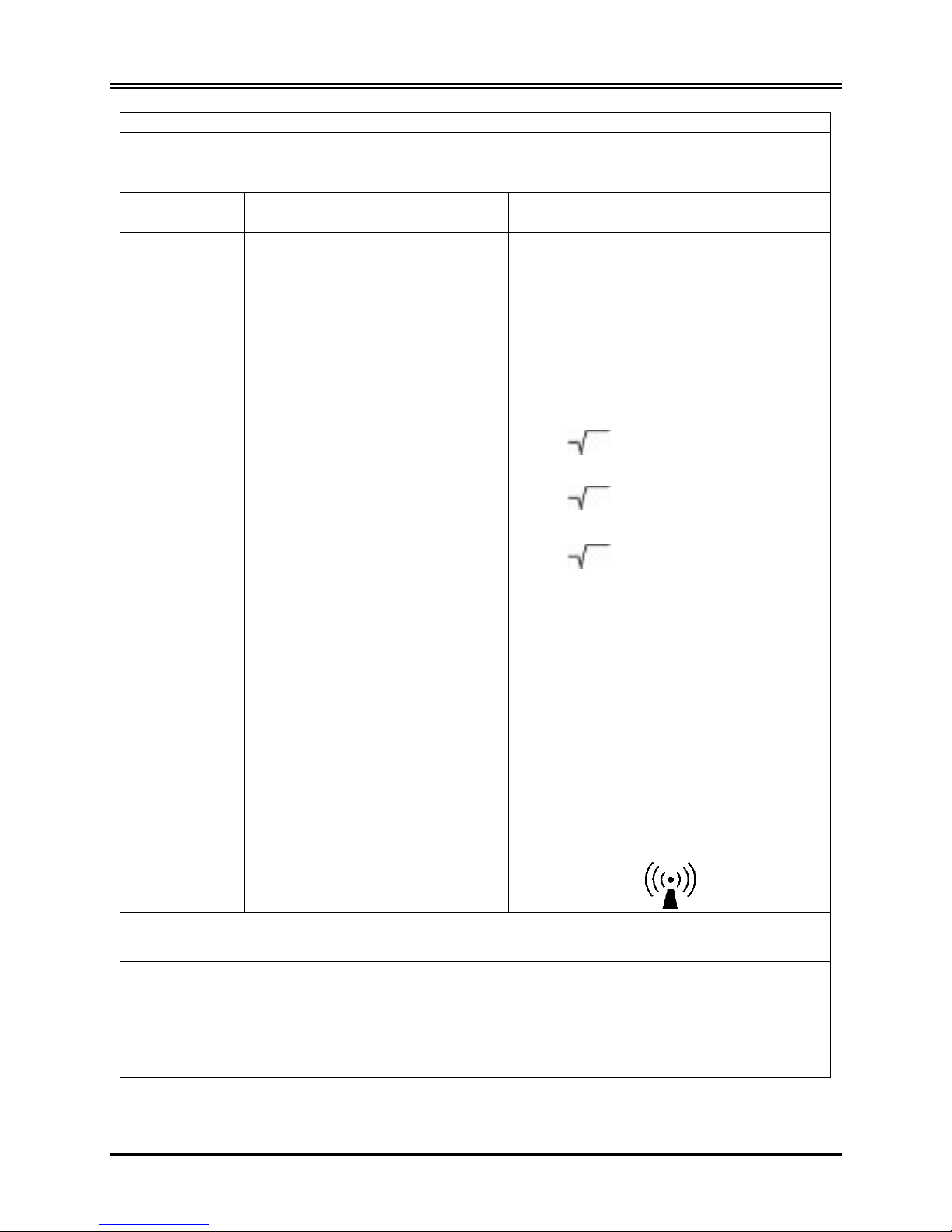
Guidance and manufacturer’s declaration – Electromagnetic emissions
The Model 7600/7800 monitor is intended for use in the electromagnetic environment specified
environment.
Emissions test
Compliance
Electromagnetic environment - guidance
RF emissions
Group 1
The Model 7600/7800 uses RF energy only for its
in nearby electronic equipment.
RF emissions
CISPR 11 Conducted
Class B
The Model 7600/7800 is su ita b le fo r use in al l
Harmonic emissions
IEC 61000-3-2
Class A
Voltage fluctuations/
IEC 61000-3-3
Class A
WARNING: The Model 7600/7800 should not be used adjacent to or stacked with other equipment.
However, if adjacent or stacked use is necessary, the Model 7600/7800 should be observed to verify normal
operation in the configuration in which it will used.
5.10 Accessories
WARNING: The use of accessories other than those specified below may result in increased emissions or
decreased immunity of the equipment.
Ivy P/N Description
590432 Low Noise, Four Lead ECG Patient Cable, 10 ft. Long, Colors: White, Green, Red, Black
590433 Set o f Four Shielded Lead Wires, 24 Inches Long, Colors: White, Green, Red, Black
590435 Se t of Four Radiotranslucent Lead Wires, 30 Inches Long, Colors: White, Green, Red, Black
590442 Set of Four Radiotranslucent Lead Wires, 36 Inches Long, Colors: White, Green, Red, Black
590446 Low Noise, Four Lead ECG Patient Cable, 10 ft. Long, IEC Colors: Red, Black, Green, Yellow
590447 Set of Four Shielded Lead Wires, 24 Inches Long, IEC Colors: Red, Black, Green, Yellow
590451 Set of Four Radiotranslucent Lead Wires, 30 Inches Long, IEC Colors: Red, Black, Green, Yellow
590452 Set of Four Radiotranslucent Lead Wires, 36 Inches Long, IEC Colors: Red, Black, Green, Yellow
590436 Radiotranslucent ECG electrodes, Box of 40 (10 pouches of 4 electrodes)
below. The customer or the user of the Model 7600/7800 should ensure that it is used in such an
CISPR 11 Radiated
flicker emissions
Class B
internal function. Therefore, their RF emission s are
very low and are not likely to cause any interference
establishments other than domestic and those
directly connected to the public low-voltage power
supply network that supplies buildings used for
domestic purposes.
8 Model 7600/7800 Operation Manual

SAFETY
Guidance and manufacturer’s declaration – Electromagnetic immunity
The Model 7600/7800 monitor is intended for use in the electromagnetic environment specified
environment.
Immunity test
IEC 60601 test
level
Compliance level
Electromagnetic environment –
guidance
Electrostatic
±6 kV contact
±9 kV contact
Floors should be wood, concrete,
least 30%.
Electrical fast
±2 kV for power
input/output lines
±3 kV for power
input/output lines
Mains power quality should be
Surge
±1 kV differential
mode
±1.5 kV
mode
Mains power quality should be
Voltage dips, short
<5 % UT
for 5 sec cycle
<5 % UT
for 5 sec cycle
Mains power quality should be
Power frequency
3 A/m
10 A/m
Power frequency magnetic fields
environment.
below. The customer or the user of the Model 7600/7800 should ensure that it is used in such an
discharge (ESD)
IEC 61000-4-2
Transient/burst
IEC 61000-4-4
IEC 61000-4-5
interruptions, and
voltage variations
on power supply
input lines
IEC61000-4-11
±8kV air
supply lines
±1 kV for
mode
±2 kV common
(>95 % dip in UT)
for 0.5 cycle
40 % U
(60 % dip in U
T
) for
T
5 cycles
70 % U
(30 % dip in U
T
) for
T
25 cycles
<5 % U
(>95 % dip in U
T
T
±12kV air
supply lines
±1.5 kV for
differential mode
±3 kV common
(>95 % dip in UT)
for 0.5 cycle
40 % U
(60 % dip in U
for 5 cycles
70 % U
(30 % dip in U
for 25 cycles
<5 % U
(>95 % dip in U
)
or ceramic tile. If floors are
covered with synthetic material,
the relative humidity should be at
that of a typical commercial or
hospital environment.
that of a typical commercial or
hospital environment.
that of a typical commercial or
hospital environment. If the user
of the Model 7600/7800 requires
T
continued operation during power
mains interruptions, it is
)
T
recommended that the Model
7600/7800 be powered from an
T
T
uninterruptible power supply.
)
T
)
T
(50/60 Hz)
magnetic field
IEC 61000-4-8
Model 7600/7800 Operation Manual 9
should be at levels characteristic
of a typical location in a typical
commercial or hospital
SAFETY
Guidance and manufacturer’s declaration – Electromagnetic immunity
The Model 7600/7800 monitor is intended for use in the electromagnetic environment specified
environment.
Immunity test
IEC 60601 test
level
Compliance
level
Electromagnetic environment – guidance
Portable and mobile RF communications
NOTE 1 – At 80 MHz and 800 MHz, the higher frequency range applies.
reflection from structures, objects, and people.
a
Field strengths from fixed transmitters, such as base stations for radio (cellular/cordless) telephones and land mobile
Over the frequency range 150 KHz to 80 MHz, field strengths should be less than 3 V/m.
below. The customer or the user of the Model 7600/7800 should ensure that it is used in such an
Conducted RF
IEC 61000-4-6
Radiated RF
IEC 61000-4-3
3 Vrms
150 kHz to 80 MHz
3 V/m
80 MHz to 2.5 GHz
5 Vrms
10 V/m
equipment should be used no closer to any
part of the Model 7600/7800, including
cables, than the recommended separa t ion
distance calculated from the equation
applicable to the frequency of the
transmitter.
Recommended separation distance
d = 1.2
p
d = 1.2 p 80 MHz to 800 MHz
d = 2.3
p 800 MHz to 2.5 GHz
Where p is the maximum output power
rating of the tran smitter in watts (W )
according to the transmitter manufacturer
and d is the recommended separation
distance in meters (m).
Field strengths from fixed RF transmitters,
as determined by an electromagnetic site
survey
level in each frequency range
a
, should be less than the compliance
b
Interference may occur in the vicinity of the
equipment marked with the following
symbol:
NOTE 2 – These guidelines may not apply in all situations. Electromagnetic propagation is affected by absorption and
radios, amateur radios, AM and FM radio broadcast, and TV broadcast cannot be predicted theoretically with accuracy. To
assess the electromagnet ic environment due to fixed R F transmitters, and electromagnetic site survey should be considered.
If the measured field strength in the location in which the Model 7600/7800 is used exceed s the applicable RF compl iance
level above, the Model 7600/7800 should be observed to verify normal operation. If abnormal performance is observed,
additional measures may be n ecessary, such as re-orienting or relocating the Model 7600/7800.
b
10 Model 7600/7800 Operation Manual

SAFETY
∼
5.11 Description of Symbols Used
Consult instructions for use Warning
Type CF Applied Part,
Defibrillator proof
Equipotential ground connector RoHS Complian t
Fuse type / rating Output Signal
Protective earth (Ground) Input Signa l
Earth (Ground) Input / Output Signal
Caution
Power On/Standby Manufacturer
Date of Manufacture Alarm Mute
WEEE Compliant
Electric shock hazard: Do not remove covers or panels. Refer service to qualified service personnel.
Model 7600/7800 Operation Manual 11
Alternating Current

MONITOR DESCRIPTION
6.0 MONITOR DESCRIPTION
The Model 7600/7800 is an easy-to-use Cardiac Trigger Monitor that features a bright color touch screen LCD
display. The Model 7600/7800 displays two simultaneous ECG vectors and the patient’s heart rate. The Trigger
ECG vector (top ECG waveform) can be selected from Leads I, II III or Auto. The Second ECG vector (bottom
ECG waveform) can be selected from Leads I, II or III. In addition, high and low heart rate alarm limits can be
adjusted to bracket the patient’s heart rate so that a violation of these limits produces an audible and visual
indication of the violation. The M odel 7600/7800 color display includes dual ECG traces, large heart rate numbers
and alphanumeric characters for other data, alarm messages, menus and user information.
• The Model 7600/7800 monitor is intended primarily for use on patients in applications r e quiring precision
R-wave synchr onization such as timed imaging studies.
• The Model 7600/7800 includes an AUTO lead select feature (Trigger lead only). When selected, this
feature will determine which lead (I, II or III) provides the best quality ECG signal and, thus, a more
reliable cardiac trigger.
• The Model 7600/7800 has an electrically isolated RS-232 micro-D connector that provides two-way
communications between the monitor and the external console for the transfer of ECG data.
• The Model 7600/7800 is available with different options; not all options are included in all monitors. An
optional integ ral recorder is av ail able. Set u p of recorder f u nctions is m ade through the monitor touch screen
menus.
• The Model 7600/7800 is suitable for use in presence of electrosurgery.
• The Model 7600/7800 is not intended for use with any other physiological monitoring unit.
• The Model 7600/7800 is restricted to use on one patient at a time.
Model 7800 Only:
• The Model 7800 has special hardware and software that allows for the measurement of skin to electrode
impedance.
• The Model 7800 provides two Ethernet channels from a single RJ45 connector. The first channel provides
two way communications between the monitor and the CT console for the transfer of ECG data, trigger
timing data and the receipt of patient identification information. The second channel provides ECG data to
the CT Gantry display. These functions will only operate when the Model 7800 is electrically connected to
a CT console and CT gantry capable of displaying ECG data.
• The Model 7800 has a USB drive that allows the operator to store and retrieve ECG data on a USB
memory stick device.
• The Mode l 7800 has an Auxiliary 9-pin D-subminiature connecto r that provides a customized interface for
specific installations.
12 Model 7600/7800 Operation Manual

MONITOR DESCRIPTION
6.1 Intended Use
The Ivy Biomedical Model 7000 Series Cardiac Trigger Monitors are simple-to-use instruments for monitoring ECG
and Heart Rate. The y are designed for us e in the ICU, CCU and operating room conditions. They can sound an
alarm when HR falls outside of preset limits. They provide an output pul s e, synchro nized to the R-wave for use in
applications requiring precision R-wave sync hronization.
6.2 Patient Population
The Model 7000 Series Cardiac Trigger Monitor is intended to perform ECG monitoring and R-wave pulse
detection on adult, geriatric, pe diatric and neonatal patients. R-Wave synchr onization i s typically used for gating
nuclear scanners, CT scanners, or other imaging devices.
6.3 Contrain dications
The Model 7000 Series is limited to use by trained and qualified medical professionals. This device is not intended
for use as life support equipment or for performing cardiac diagnostics. The product is not intended for use in home
care monito ring or for us e in an MRI e nvironment .
6.4 Classification (in accordanc e with ANSI/AAMI ES60601-1:2005)
Protection against electric shoc k: Class 1.
Degree of protection against electric shock: Type CF applied part. Defibrillator proof: ECG
Degree of protection against harmful ingress of water: Ord i nary Equipment IPX1 per IEC-60529
Methods of Maintenance and Cleaning: See Maintenance and Cleaning section of this manual
Degree of safety of application in the presence of a Equipment not suitable for use in the presence of a
flammable anesthetic mixture with air or oxygen flammable anesthetic mixture
or nitrous oxid e:
Mode of operation: Continuous
Model 7600/7800 Operation Manual 13
 Loading...