

Page 1

Installation Manual
Rego 5101
ok
6 720 641 739-37.1I
6 720 645 172 (2010/07) en
Page 2

Table of Contents
6 720 645 172 (2010/07) en
2
Table of Contents
1 Key to symbols and safety precautions . . . . . . . 3
1.1 Explanation of symbols . . . . . . . . . . . . . . . 3
1.2 Safety precautions . . . . . . . . . . . . . . . . . . 3
2 I/O connections . . . . . . . . . . . . . . . . . . . . . . . . . 4
3 Control panel . . . . . . . . . . . . . . . . . . . . . . . . . . . 5
3.1 Panel overview . . . . . . . . . . . . . . . . . . . . . 5
3.2 Status lamp . . . . . . . . . . . . . . . . . . . . . . . . 5
3.3 On/Off button . . . . . . . . . . . . . . . . . . . . . . 5
3.4 Menu display . . . . . . . . . . . . . . . . . . . . . . . 5
3.5 Return button . . . . . . . . . . . . . . . . . . . . . . 5
3.6 Navigation buttons . . . . . . . . . . . . . . . . . . 5
3.7 Alarm button . . . . . . . . . . . . . . . . . . . . . . . 5
3.8 Initial menu . . . . . . . . . . . . . . . . . . . . . . . . 6
3.9 Finding desired function and changing
values . . . . . . . . . . . . . . . . . . . . . . . . . . . . . 6
3.10 Operating information . . . . . . . . . . . . . . . . 8
3.11 Access levels . . . . . . . . . . . . . . . . . . . . . . . 9
4 Settings . . . . . . . . . . . . . . . . . . . . . . . . . . . . . . . 10
4.1 Communication . . . . . . . . . . . . . . . . . . . . 10
4.2 Settings\Addressing . . . . . . . . . . . . . . . . 11
4.3 Settings\Room temperature . . . . . . . . . . 11
4.4 Settings\Additional heat . . . . . . . . . . . . . 14
4.5 Settings\Hot water . . . . . . . . . . . . . . . . . 18
4.6 Settings\Accessories . . . . . . . . . . . . . . . . 21
4.7 Settings\Circulation pumps . . . . . . . . . . 24
4.8 Settings\Collector circuit . . . . . . . . . . . . 25
4.9 Settings\External control . . . . . . . . . . . . 25
4.10 Settings\General alarm . . . . . . . . . . . . . . 25
4.11 Settings\Inversions . . . . . . . . . . . . . . . . . 25
4.12 Settings\Sensor calibration . . . . . . . . . . 26
4.13 Function test . . . . . . . . . . . . . . . . . . . . . . 26
4.14 Quick restart . . . . . . . . . . . . . . . . . . . . . . 26
4.15 Read out . . . . . . . . . . . . . . . . . . . . . . . . . 27
4.16 Quick log-out . . . . . . . . . . . . . . . . . . . . . . 27
4.17 Factory reset . . . . . . . . . . . . . . . . . . . . . . 28
5 Information/Alarms . . . . . . . . . . . . . . . . . . . . . 29
5.1 General . . . . . . . . . . . . . . . . . . . . . . . . . . 29
5.2 Alarm categories . . . . . . . . . . . . . . . . . . . 29
5.3 Status lamp . . . . . . . . . . . . . . . . . . . . . . . 29
5.4 Alarm list and Alarm history . . . . . . . . . . 29
5.5 Acknowledgement of alarms . . . . . . . . . . 29
5.6 Alarm functions . . . . . . . . . . . . . . . . . . . . 30
5.7 Resistance table PT1000 temperature
sensor . . . . . . . . . . . . . . . . . . . . . . . . . . . 37
Page 3
Key to symbols and safety precautions
6 720 645 172 (2010/07) en
3
1 Key to symbols and safety precautions
1.1 Explanation of symbols
Warnings
Signal words indicate the seriousness of the hazard in
terms of the consequences of not following the safety
instructions.
• NOTICE indicates possible damage to property or
equipment, but where there is no risk of injury.
• CAUTION indicates possible injury.
• WARNING indicates possible severe injury.
• DANGER indicates possible risk to life.
Important information
Additional symbols
1.2 Safety precautions
General
B Re ad t h e guide c are f u lly and kee p it t o hand fo r fu t u re
use.
Installation and commissioning
B The heat pump may be installed and put into
operation only by a qualified installer.
Risk of damage due to operator error
Operator errors can result in injury and damage to
property.
B Ensure that children never operate this appliance
unsupervised or play with it.
B Ensure that only personnel who can operate this
appliance correctly have access to it.
Service and maintenance
B Only qualified personnel may carry out repairs.
Incorrect repairs can lead to serious risks to the user,
and a reduction in savings.
B Only use original spare parts.
B Service and maintenance must be carried out annually
by an authorised service representative.
Safety instructions in this document are
framed and identified by a warning triangle
which is printed on a grey background.
Electrical hazards are identified by a
lightning symbol surrounded by a warning
triangle.
Notes contain important information in
cases where there is no risk of personal
injury or material losses and are identified
by the symbol shown on the left. They are
bordered by horizontal lines above and
below the text.
Symbol Meaning
B a step in an action sequence
Æ a reference to a related part in the
document or to other related documents
• a list entry
– a list entry (second level)
Tab. 1
Page 4

I/O connections
6 720 645 172 (2010/07) en
4
2 I/O connections
Temperature inputs PT1000 HP
Ai1 E11.T1 Flow E21
Ai2 E10.T2 Outdoor E21
Ai3 E4x.T3 Hot water E2x
Ai4 T6 Hot gas E2x
Ui1 T8 Heat transfer fluid
out (flow from heat
pump)
E2x
Ui2 T9 Heat transfer fluid
in (return to heat
pump)
E2x
Ui3 T10 Collector circuit in E2x
Ui4 T11 Collector circuit out E2x
Tab. 2 Temperature inputs PT1000
Potential-free, digital inputs 24Vac HP
Di1 IND/SSM
E11.G1
Signal circulation
pump heating
system
E21
Di2 B11 EVU / External
control
E2x
Di3 E71.E1.B31
E51.B11
E2.F21
Thermostat
Differential
pressure monitor
Additional heat
alarm
E21
Di4 E1 IND Operating reply
compressor
E2x
Di5 G2.F13 Motor cut-out heat
transfer fluid pump
E2x
Di6 G3.F13 Motor cut-out
collector circuit
pump
E2x
Di7 RLP Low pressure
switch
E2x
Di8 RHP High pressure
switch
E2x
Di7+
8
K11 Safety switch E2x
Tab. 3 Potential-free, digital inputs 24Vac
Analogue outputs 0-10Vdc HP
Ao1 E71.E1.Q71
E51.Q51
Additional heat
mixing valve,
heating system
E21
Ao2
Ao3
Ao4 G2 Heat carrier pump E2x
Ao5 G3 Collector circuit
pump
E2x
Tab. 4 Analogue outputs 0-10Vdc
Digital outputs 230Vac HP
Do1 E1 Compressor E2x
Do2 E71.E1
E2.E1
Start additional heat
Internal electric
additional heat stage
1
E2x
Do3 E2.E2 Internal electric
additional heat stage
2
E2x
Do4
E4x.Q1x
Q21
3-way valve hot water
External
Internal
E2x
Tab. 5 Digital outputs 230Vac
Digital outputs potential-free (inverted) HP
Do5 E11.G1 Circulation pump,
heating system
E21
Do6 E71.E1.G71
E31.G33
Circulation pump
mixed additional
heat
External collector
circuit pump
E21
E2x
Do7 P2 General alarm (A/
AB)
E2x
Tab. 6 Digital outputs potential-free (inverted)
Accessories Quantity HP
Mixing valve/Pool/Room
sensor (Multi-regulator)
0-9 E21
Tab. 7 Accessories
Page 5
Control panel
6 720 645 172 (2010/07) en
5
3 Control panel
Settings for the control of the heat pump are made with
the control unit's control panel, which also provides
information about current status.
Each heat pump is set using its control unit.
3.1 Panel overview
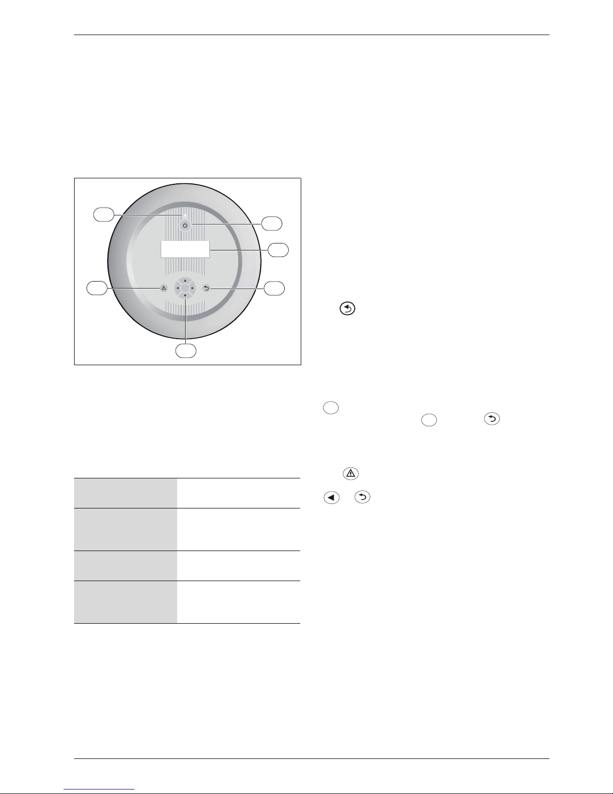
Fig. 1 Control panel
1 Status lamp
2 On/Off button
3 Menu display
4 Return button
5 Navigation buttons
6 Alarm button
3.2 Status lamp
The status lamp indications apply to the heat pump the
lamp is placed on.
3.3 On/Off button
Use the On/Off button to switch the heating installation
on and off.
When Off: The menu window shows Standby. The heat
system circulation pump E11.G1 keeps running.
Communication between the heat pumps is not
affected.
3.4 Menu display
Use the menu display in order to:
• See information from the heat pump.
• See available menus.
• Change set values.
3.5 Return button
Use to:
• Go back to the previous menu level.
• Leave a setting display without changing the set
value.
3.6 Navigation buttons
Use the arrows to navigate between the menus. Press
to initiate a value change, then use the arrows to
change the value. Press to save or to return
without saving.
3.7 Alarm button
Use to show the alarm list (status lamp lights/
flashes red). To return to the previous position, press
or .
Alarms activated in a certain pump are shown in the heat
pump in question.
The lamp lights green. The control unit is
activated.
The lamp flashes green
slowly.
The control unit is
switched off/stand-by
mode (Off).
The lamp flashes red. An alarm is active or has
not been acknowledged.
The lamp lights red. The alarm has been
acknowledged but the
alarm cause remains.
Tab. 8 Lamp functions
ok
3
4
2
1
5
6
6 720 641 739-06.1I
ok
ok
Page 6
Control panel
6 720 645 172 (2010/07) en
6
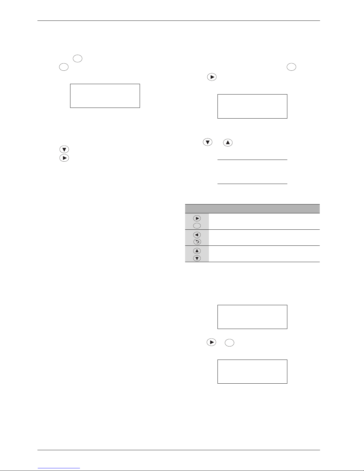
3.8 Initial menu
B To see the initial menu when the menu window is
unlit, press .
B Press for 5 seconds to become logged in as a
Customer (Æ Chapter 3.11, page 9).
The Initial menu shows the pump in question (E21),
date, time and outdoor temperature.
B Press to show the current operating information.
B Press to move to the top menu level (Customer).
The Initial menu looks the same in all heat pumps
irrespective of the heat pump's designation.
3.9 Finding desired function and changing
values
The menu overview shows the main functions that are
reached using the navigation buttons and .
B Press in the Initial menu to move to the top
menu level (Customer).
B Use and to scroll between the available
menus at menu level.
Navigate between the menus
Change a value, e.g. heat curve at 0 °C
The heat curve is only accessible in E21.
B Go to:
B Press or to go to the next menu under Room
temperature.
Rego 5101 E21
2010-03-01 14:23
Outd. -2:0 °C Menu>
Info
Tab. 9 Initial menu
ok
ok
>Room temperature
Hot water
Temperatures
Language
Tab. 10 Menu level 1 (part 1)
Language
Date/Time
>Access level
Tab. 11 Menu level 1 (part 2)
Button Function
Go to the next menu level for a menu
marked with >.
Return to the previous menu level.
Scroll between the menus at the same
level.
Tab. 12 Menu navigation
>Room temperature
Hot water
Temperatures
Language
Tab. 13 Menu level 1 (part 1)
>Summer/winter op.
Heat curve
Parallel offset
Hysteresis
Tab. 14 Room temperature 1
ok
ok
ok
Page 7
Control panel
6 720 645 172 (2010/07) en
7
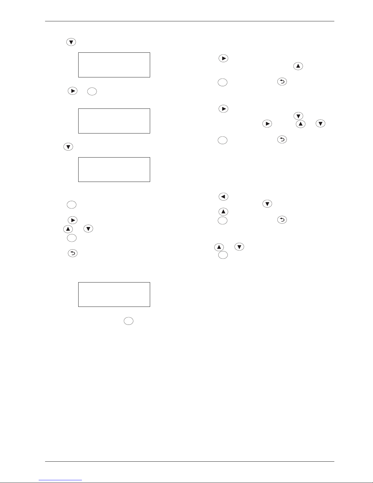
B Press so that Heat curve is marked.
B Press or to go to the next menu level for
Heat curve.
B Use till the below is shown:
The value 35 ° shall be changed to 37 °.
B Press to come to the first adjustable value, which
is 3 in 35 °. The digit is marked and flashes.
B Press so that digit 5 in 35 ° is marked.
B Use or to change 5 to 7.
B Press to save the value. The cursor is now on the
next adjustable value in the window.
B Press one or more times to cancel an initiated
change.
After change to 37 ° the window looks like this:
Digit 3 in 38 ° is marked. Press to keep the value
and continue navigating.
Other ways of changing a value
Increase the number of digits in a value:
B Press so that the cursor is placed to the right of
the last digit in the value, and press until the
desired value is shown.
B Press to save the value or one or more times
to return without saving.
Place a decimal point in a value:
B Press so that the cursor is placed to the right of
the last digit in the value, and press . A decimal
point is included. Press and use or to
set the desired value for the decimal.
B Press to save the value or one or more times
to return without saving.
When the value has been saved, it can be presented
as a whole number, even though one or more
decimals have been added. The value in the control
unit is always the saved value.
Change to/from a negative value:
B Press to mark the position in front of the first
digit in the value. Press to include a minus sign,
press to remove a minus sign.
B Press to save the value or one or more times
to return without saving.
Change a text value:
B Use or to show the available alternatives.
Press when the desired value is displayed.
Summer/winter op.
>Heat curve
Parallel offset
Hysteresis
Tab. 15 Room temperature 2
Heat curve
Outd. Flow
20 ° 20 °
15 ° 24 °
Tab. 16 Heat curve 1
Heat curve
Outd. Flow
0 ° 35 °
-5 ° 38 °
Tab. 17 Heat curve 2
Heat curve
Outd. Flow
0 ° 37 °
-5 ° 38 °
Tab. 18 Heat curve 3
ok
ok
ok
ok
ok
ok
ok
ok
Page 8

Control panel
6 720 645 172 (2010/07) en
8
3.10 Operating information
Under Info there is operating information that is reached
by pressing in the initial menu.
Operating mode: Winter operation or Summer
operation.
Demand: Shows one of the following:
Status compressor: Shows one of the following:
Rego 5101 E21
2010-03-01 14:23
Outd. -2:0 °C Menu>
Info
Tab. 19 Initial menu
Operating mode
Demand
Status compr. Time
Tab. 20 Info 1
No demand No demand for heating, hot water or
external start of the compressor.
Heating
demand
Heating demand
Hot water
demand
Hot water demand
Therm.
disinfection
Thermal disinfection
External
operation
An external unit has demanded
operation of the heat pump,
compressor and/or additional heat.
Manual
operation
Function test underway.
Tab. 21 Need
Blocked The compressor is blocked by a
tripped safety function. Information
is stored in Alarm history available at
installer level.
External
blocking
The compressor is blocked via
external control.
Off The compressor is not running.
E11.G1 is running in case of winter
operation or anti-seizure operation.
Q21/E4x.Q1x is active in case of
emergency operation, summer or
anti-seizure operation. Additional
heat is not in operation.
Press. equal. The compressor restart timer is
counting down. The time remaining
in seconds is shown.
Start-up When a demand occurs, G2 and G3
start first and run for 30 seconds to
verify function.
Checking After start-up the temperatures T6,
T8, T9, T10, T11 are checked for 3
minutes to ensure that they can
manage the protection
temperatures.
Compressor The compressor starts. T6 must rise
to a minimum of 10K above T8
within 3 minutes, otherwise the
compressor stops.
Operation The compressor runs as long as the
demand remains or external start is
active. No safety functions have
tripped, and there is no external
stop.
Stopping The compressor has stopped in this
situation. G2 and G3 run for 2
minutes. The time remaining in
seconds is shown.
Oper.+
Add.heat
Both the compressor and the
additional heat are in operation.
Tab. 22 Status compressor
Page 9

Control panel
6 720 645 172 (2010/07) en
9
B Use for more information under Info.
Shows the actual value for a given sensor and the set
point for E11.T1.
Shows the actual value and stop temperature for the hot
water sensor as well as the mixing valve position. Is only
shown in heat pumps that produce hot water.
Shows the actual value for the given sensors.
0 = Off, 1 = On (Æ Chapter 2, page 4 for information on
I/O-connections).
Shows present utilisation in % (Æ Chapter 2, page 4 for
information on I/O-connections).
B Use several times to return to the Initial menu.
Information is also available at different places in the
menus, e.g. under Temperatures at the top menu level.
3.11 Access levels
Log in must be done per heat pump.
Log in as a customer:
B Press for 5 seconds in the Initial menu.
Log in as installer:
B Enter password mmdd under Access level.
mm = current month
dd = current day
E.g.: 0315 = 15th March.
Logging out:
B Use function Quick log-out on installer level or wait.
External sensors
E11.T1 35:2 °C
E11.T1 spv 36.2 °C
E10.T2 3.9 v °C
Tab. 23 External sensors 1
External sensors
E41.T3 56.4 °C
Stop 57.0 °C
E41.Q11 Off
Tab. 24 External sensor 2
Internal sensors
T6 87.0 ( °C)
T8 36.2 T10 5.0
T9 29.2 T11 2.0
Tab. 25 Internal sensors
Status digital I/O
vvvvv1 2 3 4 5 6 7 8
In: vv0 0 0 1 1 1 1 1
Out: 1 0 0 0 1 0 1
Tab. 26 Status digital I/O
Status analogue out
Ao1: 0.0 (%)
Ao2: 0.0 Ao4: 64:3
Ao3: 0.0 Ao5: 52.8
Tab. 27 Status analogue out
Program version
x.x– x– xx
Tab. 28 Program version
Not logged in See a small number of settings.
Customer See and change customer settings.
Logging out after 10 min.
Installer According to the Customer and see
and change more settings. Logging
out after 30 min.
Tab. 29 Access levels
ok
Page 10

Settings
6 720 645 172 (2010/07) en
10
4 Settings
After logging on as installer (Æ Chapter 3.11, page 9)
Installer is displayed directly under Access level on the
top menu level. Menu line Communication is displayed
before Access level.
Under Installer are the following main functions:
• Settings
• Function test
• Quick restart
• Read out
• Quick log-out
• Factory reset
All settings are made under Settings. This section
includes:
• Addressing
• Room temperature
• Additional heat
• Hot water
• Accessories
• Circulation pumps
• Collector circuit
• External control
• General alarm
• Inversions
• Sensor calibration
Menu tables
The available functions and settings are shown in the
following menu tables.
Factory: Pre-set values, most of which can be changed.
Range: Gives available setting alternatives or possible
value limitations.
HP: Gives the heat pump in which the function is
available.
4.1 Communication
Settings at customer level are in the User
Manual for Greenline HE.
Always set E21 first. Most settings are made
here because for example Additional heat
and accessories are connected to this heat
pump. The settings in E21 also affect other
heat pumps.
Setting Factory Range HP
Communication
Modbus server
Address:
Speed:
1,8,N,2
1
19200 bps
1-247
2400
4800
9600
19200
E2x
B Set the valid address for the heat pump. Each heat pump must have a unique address.
The function is used for monitoring/control from external equipment (3rd party). Data is retrieved separately from all units
that are to be monitored. The communication is Modbus/RTU, RS485.
Operation times, operating status, alarm status, temperatures, set point values, limit values etc are read off via
communication. The set point values can be changed and the heat pump can be force started and force stopped.
The settings do not affect the heat pump operation or cooperation.
Tab. 30 Communication
Page 11

Settings
6 720 645 172 (2010/07) en
11
4.2 Settings\Addressing
4.3 Settings\Room temperature
Setting Factory Range HP
Addressing
Heat pumps
Number:
This HP:
1
E21
1- 9
E21- E29
E21
E2x
B Set the number of heat pumps in E21.
B State the valid designation of the heat pump in each heat pump in accordance with the system drawing.
By setting Number and This HP all cooperation, addressing and port setting is arranged automatically.
Tab. 31 Addressing
Setting Factory Range HP
Room temperature
Summer/winter
op.
Summer operation
Start:
T2 >
in
17 °C
180 min
E21
Winter operation
T2 <
in
15 °C
300 min
E21
Winter operation
Direct start:
T2 < 7 °C
E21
B Set the outdoor temperature that is required for changeover to summer operation, and the delay
that applies.
B Set the outdoor temperature that is required for changeover to winter operation, and the delay
that applies.
B Set the outdoor temperature at which winter operation shall start directly, without a delay.
Delays prevent repeated stops and starts of the heating system circulation pump when the outdoor
temperature fluctuates above and below the limit.
Basic setting Basic setting
DOT
Min
Max
-35 °C
20 °C
60 °C
E21
The factory settings refer to radiator systems. For underfloor heating systems only, 35 °C is
recommended as the highest flow set point. Other applications may require other values.
B Set the minimum outdoor temperature for the heat curve (DOT), and the lowest and highest flow
temperature set points.
Heat curve E21
The flow temperature set points at different outdoor temperatures are automatically calculated using
the values in Basic setting, Æ Chapter 4.3.1 for example on heat curve for radiator systems and
underfloor systems. Values can be changed individually, for example adjusting the heat curve at 0 °C.
Parallel offset
Parallel offset 0 K E21
B Enter by how many degrees the flow temperature at the curve's outdoor temperatures shall be
adjusted down or up.
Tab. 32 Room temperature
Page 12

Settings
6 720 645 172 (2010/07) en
12
4.3.1 Heat curve
The heat pump operates by holding flow temperature
E11.T1 in relation to outdoor temperature E10.T2
according to the set heat curve.
The appearance of the heat curve depends on settings
for the minimum outdoor temperature (DOT, factory
setting -35 °C), lowest flow set point (factory setting
20 °C) and highest flow set point (60 °C). This heat
curve is appropriate for radiator systems.
Fig. 2 Radiator system
When the factory setting is changed, the heat curve is
redrawn automatically. Any adjustments to the curve
disappear.
The curve is set in E21 and applies to all heat pumps.
Example of a floor heating curve:
Fig. 3 Floor heating
Hysteresis Hysteresis
Min
Max
Time factor
2 K
8 K
30
E2x
Hysteresis
Actual v.
E11.T1
Set point
Display K
Display °C
Display °C
E2x
The factory settings refer to heating systems with normal flow. For low flow systems Min 3 K, Max 16
K is recommended. For high flow systems (floor heating) Min 1 K, Max 4 K is recommended.
B Set the minimum and maximum hysteresis and time factor for hysteresis reduction after start/stop.
Current hysteresis, as well as actual value and set point for E11.T1 are shown.
Attenuation
E10.T2
Attenuation E10.T2 2h E21
The function means that the set point for the flow temperature is successively adjusted with respect
to the set point at the current outdoor temperature. This reduces the effect of brief fluctuations in
outdoor temperature.
B Set the time for the flow temperature set point to reach the current curve value.
Deviation E11.T1
Deviation E11.T1 10 K E21
B Set how much lower/higher than the set point T1 must be for 30 min to give an alarm
(Æ Chapter 5.6.32, page 34).
Setting Factory Range HP
Tab. 32 Room temperature
6 720 614 789-15.3I
T
1(˚C)
T2(˚C)
20 15 10 5 0 -5 -10 -15 -20 -25 -30 -35
80
70
60
50
40
30
20
10
6 720 641 739-54.1I
T
1(˚C)
T2(˚C)
20 15 10 5 0 -5 -10 -15 -20 -25 -30 -35
80
70
60
50
40
30
20
10
Page 13

Settings
6 720 645 172 (2010/07) en
13
B Draw in your own curve:
Fig. 4 Own curve
4.3.2 Hysteresis
Hysteresis floats between a max value and a min value.
A time factor determines the time it takes to go from
maximum to minimum value.
The values are set in each heat pump. The current
hysteresis is calculated and displayed in each heat pump
as well as E11.T1's actual value and set point value. The
heat pump that has been out of operation the longest
starts first, that which has operated longest stops first.
4.3.3 Heating demand
The heating demand is activated in each heat pump
when E11.T1 falls below the heat curve set point with
current hysteresis. The heating demand is deactivated
when E11.T1 exceeds the set point with current
hysteresis.
Hot water mode and external control are superior
functions.
No heat is produced in summer operation, apart from for
a pool if applicable.
6 720 641 739-53.1I
T
1(˚C)
T2(˚C)
20 15 10 5 0 -5 -10 -15 -20 -25 -30 -35
80
70
60
50
40
30
20
10
Page 14

Settings
6 720 645 172 (2010/07) en
14
4.4 Settings\Additional heat
The tables display the settings for different types of
additional heat:
• Internal add. heat E2 (3 step)
• District heating E51
• Modulated add. heat E71
• Mixed add. heat E71
B Read more about additional heat (Æ Chapter 4.4.1 -
4.4.7).
Setting Factory Range HP
Additional heat
Additional heat type No additional heat
Comp. + add. heat
No additional heat
Internal add. heat
District heating
Modulated add. heat
Mixed add. heat
Only additional heat
Comp. + add. heat
Only compressor
E21
B Set applicable Additional heat type and desired additional heat operation. In Internal add.
heat is shown:
Settings
Start E2.E1
Hysteresis
Delay
Actual v.:
3 K
180 °min
Display, can be changed
E21
Start E2.E2
Delay
Actual v.:
60°min
Display, can be changed
Start E2.E3
Delay
Actual v.:
60°min
Display, can be changed
Stop E2.E1
Delay
Actual v.:
10°min
Display, can be changed
Stop E2.E2
Delay
Actual v.:
5°min
Display, can be changed
Stop E2.E3
Delay
Actual v.:
5°min
Display, can be changed
Settings
Max no. of steps in:
Heating:
Hot water:
2
2
0, 1, 2, 3
0, 1, 2, 3
B Set conditions for when respective stages must connect/disconnect.
B Set how many steps may be used as a maximum for heating mode and hot water mode.
ECO-drive
ECO-drive
Start
Stop after
No
22:00
6 hr
No, Yes
00:00 - 23:59
E21
B Indicate Yes if activation of the additional heat is to be delayed during a set time period.
The delay increases by 25% for the first stage.
Tab. 33 Internal electric additional heat
Page 15

Settings
6 720 645 172 (2010/07) en
15
Setting Factory Range HP
Additional heat
Additional heat type No additional heat
Comp. + add. heat
No additional heat
Internal add. heat
District heating
Modulated add. heat
Mixed add. heat
Only additional heat
Comp. + add. heat
Only compressor
E21
B Set applicable Additional heat type and desired additional heat operation. In District heating
is shown:
Settings
Start E51
Hysteresis
Delay
Actual v.:
3 K
180 °min
Display, can be changed
E21
Stop E51
Delay
Actual v.:
10°min
Display, can be changed
PID E51
P:
I:
D:
T1, Sp, Out
1
100
0
Display
B Set conditions for engaging/disengaging the additional heat.
B Set values for mixing valve control.
Actual and set point value for T1 is shown. In addition the output signal is shown in %.
ECO-drive
ECO-drive
Start
Stop after
No
22:00
6 hr
No, Yes
00:00 - 23:59
E21
B Indicate Yes if activation of the additional heat is to be delayed during a set time period.
The delay increases by 25%.
Tab. 34 Additional heat District heating
Page 16

Settings
6 720 645 172 (2010/07) en
16
4.4.1 Internal add. heat
The internal additional heat has three steps, E2.E1 (4.5
kW), E2.E2 (4.5 kW) and E2.E3 (6.75 kW). When all
stages are connected a total of 15.75 kW is obtained. A
degree minute calculation is used to activate each stage.
E2.E1: The compressor is running and E11.T1 does not
reach its set point value. Calculation of difference
between E11.T1 set point value – set Hysteresis (3 K)
and E11.T1 actual value are added continuously. When
the sum reaches the value set in Delay (180 °min) stage
1 is activated.
E2.E2: Stage 1 is connected and E11.T1 does not reach
its set point value. Calculation of difference between
E11.T1 set point value – set Hysteresis (3 K ) and E11.T1
actual value are added continuously. When the sum
reaches the value set in Delay (60 °min) stage 2 is
activated.
E2.E3: Stage 2 is connected and E11.T1 does not reach
its set point value. Calculation of difference between
E11.T1 set point value – set Hysteresis (3 K ) and E11.T1
actual value are added continuously. When the sum
Setting Factory Range HP
Additional heat
Additional heat type No additional heat
Comp. + add. heat
No additional heat
Internal add. heat
District heating
Modulated add. heat
Mixed add. heat
Only additional heat
Comp. + add. heat
Only compressor
E21
B Set applicable Additional heat type and desired additional heat operation. In Modulated add.
heat and Mixed add. heat is shown:
Settings
Start E71
Hysteresis
Delay
Actual v.:
3 K
180 °min
Display, can be changed
E21
Stop E71
Delay
Actual v.:
10°min
Display, can be changed
PID E71
P:
I:
D:
T1, Sp, Out
1
100
0
Display
B Set conditions for engaging/disengaging the additional heat.
B Set values for mixing valve control.
Actual and set point value for T1 is shown. In addition the output signal is shown in %.
Alarm delay
Alarm delay 30 min E21
The function is only displayed at Mixed add. heat.
B Set with what time alarm External add. heat out of order is to be delayed (Æ Chapter 5.6.25,
page 33).
ECO-drive
ECO-drive
Start
Stop after
No
22:00
6 hr
No, Yes
00:00 - 23:59
E21
B Indicate Yes if activation of the additional heat is to be delayed during a set time period.
The delay increases by 25%.
Tab. 35 Modulated additional heat, Mixed additional heat
Page 17

Settings
6 720 645 172 (2010/07) en
17
reaches the value set in Delay (60 °min) stage 3 is
activated.
Disconnection: Stage 3 is disconnected when the degree
minute calculation for the difference between E11.T1
actual value and E11.T1 set point value reaches the set
Delay (5 °min). The same applies to stage 2. Stage 1 is
disconnected when the degree minute calculation
reaches the set Delay (10 °min).
The additional heat demand ceases when all stages are
disconnected.
When the internal additional heat is activated the max
limit for T8 is increased to 75 °C. The limit is reset to
65 °C when the additional heat is disconnected.
4.4.2 Modulated add. heat E71
The external additional heat is controlled with 0-10V and
regulated using a PID regulator to maintain the E11.T1
set point value.
A degree minute calculation is used for connection/
disconnection.
Connection: E11.T1 does not reach its set point value.
Calculation of difference between E11.T1 set point
value – set Hysteresis (3 K) and E11.T1 actual value are
added continuously. When the sum reaches the value set
in Delay (180 °min) the additional heat is activated.
The output signal from the PID regulator controls how
much additional heat shall be produced.
Disconnection: The additional heat is disconnected
when the degree minute calculation for the difference
between E11.T1 actual value and E11.T1 set point value
reaches the set Delay (10 °min). The calculation starts
when the output signal from the PID regulator is 0.
4.4.3 Mixed add. heat E71
The external additional heat Q71 mixing valve is
controlled with 0-10V and regulated using a PID
regulator to maintain the E11.T1 set point value.
A degree minute calculation is used for connection/
disconnection.
Connection: E11.T1 does not reach its set point value.
Calculation of difference between E11.T1 set point
value – set Hysteresis (3 K) and E11.T1 actual value are
added continuously. When the sum reaches the value set
in Delay (180 °min) the additional heat is activated.
The additional heat and any internal circulation starts.
When the thermostat E71.E1.P111 acknowledges that
the additional heat has reached its operating
temperature mixing commences.
The output signal from the PID regulator controls how
much additional heat shall be produced.
Disconnection: The additional heat is disconnected
when the degree minute calculation for the difference
between E11.T1 actual value and E11.T1 set point value
reaches the set Delay (10 °min). The calculation starts
when the output signal from the PID regulator is 0.
4.4.4 District heating E51
Differential pressure switch E51.B11 at the district
heating heat exchanger must indicate the correct
direction of flow to permit opening of mixing valve Q51.
Q51 is controlled with 0-10V and regulated using a PID
regulator to maintain the E11.T1 set point value.
A degree minute calculation is used for connection/
disconnection.
Connection: E11.T1 does not reach its set point value.
Calculation of difference between E11.T1 set point
value – set Hysteresis (3 K) and E11.T1 actual value are
added continuously. When the sum reaches the value set
in Delay (180 °min) the additional heat is activated.
The output signal from the PID regulator controls how
much additional heat shall be produced.
Disconnection: The additional heat is disconnected
when the degree minute calculation for the difference
between E11.T1 actual value and E11.T1 set point value
reaches the set Delay (10 °min). The calculation starts
when the output signal from the PID regulator is 0.
4.4.5 Additional heat alarm
On alarm from the additional heat all degree minute
calculations are reset.
4.4.6 Additional heat operation
Normally Comp. + add. heat applies. When Only
additional heat is set the additional heat is activated
instead of the compressor during a heat demand.
In Internal add. heat the additional heat is also activated
during a hot water demand.
4.4.7 Hysteresis E11.T1
When an additional heat demand exists the hysteresis
for E11.T1 is held at its maximum.
4.4.8 PID regulator
P factor regulation is used.
Page 18

Settings
6 720 645 172 (2010/07) en
18
4.5 Settings\Hot water
Setting Factory Range HP
Hot water
Hot water type No hot water No hot water
Local sensor
Communicated
Previous HP
E2x
Not E21
When the heat pump is to produce hot water:
B Enter how the heat pump is to control hot water production.
B Select Local sensor when there is a locally connected hot water cylinder with local sensor to
measure the hot water temperature.
B Select Previous HP when the heat pump receives values for the hot water temperature from
the previous heat pump.
B Select Communicated when the heat pump has all information about the hot water
temperature and start/stop limits via communicating (Modbus) control (Æ Chapter 4.1,
page 10).
Temperatures
Actual v.:
Start:
Stop:
Max temperature:
Display
53 °C
57 °C
Display
E2x
B Set start and stop values for hot water production.
The factory settings refer to heat pumps with Local sensor. In Previous HP 2 K lower
temperatures are recommended. In Communicated the values have no meaning.
Max temperature displays the calculated possible highest hot water temperature.
Tab. 36 Hot water
Page 19

Settings
6 720 645 172 (2010/07) en
19
Settings
(Hot water type =
Local sensor)
Settings
Alarm setting
Alarm limit:
Delay
45 °C
30 min
E2x
B Set with what time alarm Low temperature T3 hot water is to be delayed (Æ Chapter 5.6.34,
page 34).
Settings
Valve:
Emergency operation:
External
No
External, Internal
No, Yes
E2x
B Enter type of three-way valve to get the correct designation in the control unit.
External = E4x.Q1x, Internal= Q21
B Indicate Yes if Emergency operation for hot water should be able to occur in event of
problems, Æ Chapter 4.5.3, page 20 for description of the function.
Settings
Monitor E11.T1:
Set point - T1 >
Delay
No
10 K
10 min
No, Yes
E2x
B Select Yes when the heat pump must monitor E11.T1 during hot water production.
B Enter the maximum number of degrees (K) the flow temperature T1 may be below its set point
value.
B Enter how long the flow temperature must be below the set limit before the heat pump
changes to heating mode.
At more than one heat pump all heat pumps except E21 switch to heating mode 2 degrees (K)
below E21's limit (10 K-2 K = 8 K at 10 K factory value ).
Settings
Heat protection:
T1 - Set point>
T1 increase >
No
10 K
15 K
No, Yes
E2x
B Select Yes when the heat pump must monitor E11.T1 during hot water production.
B Enter the maximum number of degrees (K) the flow temperature T1 may exceed its set point
value and how many degrees (K) T1 may increase during hot water production.
When both conditions are fulfilled the heat pump gives an alarm Problem with E4x.Q1x 3-way
valve or Problem with Q21 3-way valve (Æ Chapter 5.6.21, page 33).
Therm. disinfection
(Hot water type =
Local sensor)
Therm. disinfection
Day:
Start:
Number of steps:
No
02:00
1
No, Yes
None, Day, All
00:00 - 23.59
1, 2, 3
E21
B Select Yes if thermal disinfection is to occur. Indicate frequency and time of start.
B Select number of stages for the internal electric additional heat that is to be used by the
function.
The function can only occur in heat pumps with internal electric additional heat. It starts
according to settings and is active until T3 exceeds 70 °C or has operated for three hours. If
70 °C is not reached in that time an alarm is given Therm. disinfection unsuccessful
(Æ Chapter 5.6.43, page 35), and a new attempt is made on the next occasion.
TwinKick
(Hot water type =
Local sensor)
TwinKick No No, Yes E21
(installation
with 1 HP)
B Select Yes if the function should be active.
After heating mode a hot water demand is initiated if the hot water is lower than half the
difference to the stop limit. After hot water production a heating demand is initiated if the flow
temperature is lower than one degree below the set point value. Hysteresis is set to maximum.
Setting Factory Range HP
Tab. 36 Hot water
Page 20

Settings
6 720 645 172 (2010/07) en
20
4.5.1 Hot water temperatures
A start temperature and a stop temperature is set for
E4x.T3. If the sensor is local T9 is automatically set to
the same stop temperature in the heat pump.
Highest permitted stop temperature for hot water
decreases when T11 (heat transfer fluid out) in the heat
pump falls below - 2 °C. If necessary the control unit also
adjusts the start temperature so that it is below the stop
temperature by at least 2 K.
4.5.2 Hot water demand
Hot water demand arises when T3 falls below its start
temperature and ceases when T3 exceeds its stop
temperature. With a local sensor, T9 must also exceed
the stop limit.
4.5.3 Emergency operation, hot water
If the function is activated and local sensor T3 is not
working, hot water production is switched over to
emergency mode. 120 minutes after the previous hot
water production, the 3-way valve switches over to hot
water and a start signal is given to G2. This happens
whether the compressor is running or not. If T9 is below
the T3 start temperature, hot water demand is activated,
otherwise the 3-way valve changes back to its previous
position. The hot water demand ceases when T9
exceeds its and T3's joint stop temperature.
Page 21

Settings
6 720 645 172 (2010/07) en
21
4.6 Settings\Accessories
Accessory Multiregulator is used as a room sensor or a
mixing valve regulator. How the regulator is used in the
system is determined by selecting the function for each
accessory unit in the control unit. Accessory 1 must have
physical address 21, which is set in the unit during
installation. Accessory 2 must have physical address 22
etc.
B Set the physical address of the respective accessories
and connect the accessories before settings in the
control unit.
Setting Factory Range HP
Accessories
Accessories
Number:
Set unit
0
x
0-9
E21
B Set each accessory.
Accessories x
Select function:
Room sensor
Active room sensor
Fixed sp heating
Own heat curve
E11 heat curve
Fixed sp cooling
Pool
E21
B Select the correct function for each accessory installed.
B Use and to scroll through the settings.
In Room sensor Room sensor
Actual v.:
Display
E21
In Active room
sensor
Active room sensor
Actual v.:
Set point:
Average:
Display
22 °C
Display
E21
B Set the set point value for the room temperature.
With several active room sensors their average value is calculated and shown. This value together with
the factor set in Room temp. influence is used to affect E11.T1's heat curve.
In Fixed sp
heating
Fixed sp heating
Actual v.:
Set point:
Settings> Fixed sp heating
P:
I:
Deviation:
Pump:
Display
0°C
0
0
0 K
Off Winter, Summer, Off, On
E21
B Set the fixed set point value that must apply.
B Set appropriate values for P and I.
B Set the temperature deviation that shall cause an alarm Accessory x temp. deviation
(Æ Chapter 5.6.51, page 36).
B Enter pump function. Winter means that the accessory circulation pump is in operation during winter
operation.
The unit uses an externally connected sensor to control a 0-10V connected mixing valve to maintain
the stated fixed set point value.
Tab. 37 Accessory
Page 22

Settings
6 720 645 172 (2010/07) en
22
In Own heat
curve
Own heat curve
Actual v.:
Set point:
Settings> Own heat curve
P:
I:
Deviation:
Pump:
Display
0°C
0
0
0 K
Off Winter, Summer, Off, On
E21
B Set the heat curve that shall apply for the unit in Set point curve.
B Set appropriate values for P and I.
B Set the temperature deviation that shall cause an alarm Accessory x temp. deviation
(Æ Chapter 5.6.51, page 36).
B Enter pump function. Winter means that the accessory circulation pump is in operation during winter
operation.
The unit uses an externally connected sensor to control a 0-10V connected mixing valve to maintain
the set point value according to settings in Set point curve.
In E11 heat
curve
E11 heat curve
Actual v.:
Offset:
Settings> E11 heat curve
P:
I:
Deviation:
Pump:
Display
0 K
0
0
0 K
Off Winter, Summer, Off, On
E21
B Set appropriate values for P and I.
B Set the temperature deviation that shall cause an alarm Accessory x temp. deviation
(Æ Chapter 5.6.51, page 36).
B Enter pump function. Winter means that the accessory circulation pump is in operation during winter
operation.
The unit uses an externally connected sensor to control a 0-10V connected mixing valve to maintain
the set point value according to the heat curve for E11.T1.
In Fixed sp
cooling
Fixed sp cooling
Actual v.:
Set point:
Settings> Fixed sp cooling
P:
I:
Deviation:
Pump:
Display
0°C
0
0
0 K
Off Winter, Summer, Off, On
E21
B Set the fixed set point value that must apply.
B Set appropriate values for P and I.
B Set the temperature deviation that shall cause an alarm Accessory x temp. deviation
(Æ Chapter 5.6.51, page 36).
B Enter pump function. Summer means that the accessory circulation pump is in operation during
summer operation.
The unit uses an externally connected sensor to control a 0-10V connected mixing valve to maintain
the stated fixed set point value.
Setting Factory Range HP
Tab. 37 Accessory
Page 23

Settings
6 720 645 172 (2010/07) en
23
4.6.1 PI regulator
For accessories other than Room sensor or Active room
sensor the PI regulator for the mixing valve must be set.
P band regulation is used.
In Pool Pool
Actual v.:
Set point:
Settings> Pool
P:
I:
Deviation:
Pump:
Display
0°C
0
0
0 K
Off Winter, Summer, Off, On
E21
B Set the fixed set point value that must apply.
B Set appropriate values for P and I.
B Set the temperature deviation that shall cause an alarm Accessory x temp. deviation
(Æ Chapter 5.6.51, page 36).
B Enter pump function. Summer means that the accessory circulation pump is in operation during
summer operation.
The unit uses an externally connected sensor to control a 0-10V connected mixing valve to maintain
the stated fixed set point value.
In Own heat
curve
Set point curve E21
B Set the set point value for the circuit flow at different outdoor temperatures. For the heat curve's
lowest outdoor temperature DOT the same value as for E11's heat curve applies.
Room temp.
influence
Room temp. influence 00-10E21
Settings are shown if there is one or more active room sensors installed. With several room sensors,
comparison with the average of the sensor's actual values occurs.
B Set how much a one degree difference in room temperature (actual/average value compared to set
point) shall influence the flow temperature set point for E11.T1.
Example: At 2 K deviation from the set room temperature, the set point for the flow temperature is
changed by 6 K when the influence is set at factor 3. At 0, there is no influence.
Setting Factory Range HP
Tab. 37 Accessory
Page 24

Settings
6 720 645 172 (2010/07) en
24
4.7 Settings\Circulation pumps
Setting Factory Range HP
Circulation pumps
Settings E11.G1 Settings E11.G1
Alarm:
Operating mode:
SSM
Automatic
None, Oper. reply, SSM
Continuous, Automatic
E21
B Set if/how G1 should give an alarm in event of a problem. Alarm Operating error pump G1 can
occur when SSM or Oper. reply (Æ Chapter 5.6.27, page 34).
B Select if G1 should run in continuous or automatic operation.
In Automatic G1 runs in winter operation and is stationary in summer operation, except for
anti-seizure mode.
In the event of an operating fault in E11.G1 and all accessory pumps, all heat production stops
and alarm Oper. error all G1 (category A, Æ Chapter 5.6.1, page 30) is displayed. This alarm is
displayed also in the cases where there is only E11.G1 because all heat production stops.
Settings G2 Settings G2
At Regulating:
Set point T8-T9:
Heat:
DHW:
At Fixed speed:
Fixed speed:
Heat:
DHW:
Regulating
7 K
7 K
100%
100%
Regulating, Fixed speed
5-10 K
5-10 K
30-100%
30-100%
E2x
B Set how G2 should function.
B In Regulating: Set the temperature difference T8-T9 that the heat carrier pump must maintain
in heating mode and hot water mode respectively.
B In Fixed speed: Set the desired speed in %.
Settings G3 Settings G3
At Regulating:
Set point T10-T11:
At Fixed speed:
Fixed speed:
3 K
100%
Regulating, Fixed speed
2-6 K
30-100%
E2x
B Set how G3 should function.
B In Regulating: Set the temperature difference T10-T11 that the collector circuit pump must
maintain.
B In Fixed speed: Set the desired speed in %.
Settings Do6 Settings Do6
Pump function: None
None, E31.G33,
E71.E1.G71
E2x
E21
B Select the alternative applying to Do6 connection.
At E71.E1.G71: The pump starts at the same time as the mixed additional heat and continues for
2 minutes after the additional heat stop.
At E31.G33: The external collector circuit pump starts and stops at the same time as heat pump
collector circuit pump G3.
Tab. 38 Circulation pumps
Page 25

Settings
6 720 645 172 (2010/07) en
25
4.8 Settings\Collector circuit
4.9 Settings\External control
4.10 Settings\General alarm
4.11 Settings\Inversions
Setting Factory Range HP
Collector circuit
Collector circuit T10: Start
T10: Stop
T11: Start
T11: Stop
– 5 °C
– 8 °C
– 5 °C
– 8 °C
– 8 °C – +30 °C
– 8 °C – +30 °C
– 8 °C – +30 °C
– 8 °C – +30 °C
E2x
B Set the suitable values for collector circuit in (T10) and out (T11).
B For rock/earth – 5, – 8, – 5, – 8 °C (factory settings) are recommended.
B 1, 0, 0, – 3 °C is recommended for exhaust air.
B 4, 3, 3, 0 °C is recommended for groundwater.
Tab. 39 Collector circuit
Setting Factory Range HP
External control
External input B11
Select function:
Block all No effect
Block all
Block add. heat
Block compressor
Block hot water
Start comp+add.heat
Start compressor
E2x
B Select the function applicable for how the external input B11 (Di2) must affect the heat pump
when the input closes.
Tab. 40 External control
Setting Factory Range HP
General alarm
General alarm A/B alarm A/B alarm, A alarm E2x
B Select whether the general alarm output Do7 is to be activated for both A and B alarms or only
for A alarms.
Tab. 41 General alarm
Setting Factory Range HP
Inversions
Digital inputs
Di1
Di2
Di3
Normal
Normal
Normal
Normal, Inverted
Normal, Inverted
Normal, Inverted
E2x
B Select Inverted if the unit connected to the input requires it.
Tab. 42 Inversions
Page 26

Settings
6 720 645 172 (2010/07) en
26
4.12 Settings\Sensor calibration
4.13 Function test
4.14 Quick restart
Setting Factory Range HP
Sensor calibration
Sensor calibration
E11.T1
E10.T2
E4x.T3
0.000 K
0.000 K
0.000 K
E21
E21
E2x HW
B Check the sensors and adjust the measurement value if necessary.
Tab. 43 Sensor calibration
Setting Factory Range HP
Function test
Digital outputs Do1 – Do7
Function: Auto
Off, On, Auto
E2x
Analogue outputs
Ao1 – Ao5
Function:
Manual value:
Auto
%
Manual, Auto
E2x
B Function test all inputs and outputs in conjunction with commissioning.
B Set Auto after completed test.
Otherwise an alarm occurs Output in wrong pos after function test (Æ Chapter 5.6.30,
page 34).
The control unit gives a recommended setting for each output in brackets on the fourth line of the
menu window.
Tab. 44 Function test
Setting Factory Range HP
Quick restart
Quick restart
Actual v.:
No
Display
No, Yes E2x
B Select Yes if the restart time for the compressor is to be changed from 10 minutes to 20
seconds.
The time remaining in seconds is shown.
Yes can only be selected when the restart timer is counting at 10 minutes. After changing, the
value automatically resets to No.
Tab. 45 Quick restart
Page 27

Settings
6 720 645 172 (2010/07) en
27
4.15 Read out
4.16 Quick log-out
Read out/Setting HP
Read out
I/O-status Digital inputs E2x
B Read status of the inputs. Displayed as 0 (Off) or 1 (On).
Digital outputs E2x
B Read status of the outputs. Displayed as 0 (Off) or 1 (On).
Analogue inputs E2x
B Read temperatures for the inputs.
Analogue outputs E2x
B Read opening degree/speed in % for the outputs.
Temperatures Internal sensors E2x
B Read off temperatures for sensor T6, T8, T9, T10, T11.
External sensors E2x
B Read temperatures for sensor E11.T1, E10.T2, T3. The set point for E11.T1 and stop
temperature for T3, valve and valve operation mode are also shown.
Operating times Total E2x
B Read the total number of starts and hours for Compressor, Hot water, Winter operation,
Additional heat.
Additional heat is displayed in E21.
Short time E2x
B Read the number of starts and hours for Compressor, Hot water, Winter operation,
Additional heatfor the time after reset.
Additional heat is displayed in E21.
Alarm settings E2x
B Indicate Yesif short run time will be monitored for Heatingand/or Hot water.
Information alarm Short oper. time in heating modeand/or Short oper. time in hot water
modecan now perform (Æ Chapter 5.6.44, 5.6.45, page 35).
Logging Heating, Additional heat, Hot water, etc E2x
B Set a number of hours back in time and see the status/temperatures etc at that point in time.
The values are stored each whole hour and 168 hours (=1 week) are stored.
B Use and to scroll between the different windows.
Additional heat is displayed in E21.
Alarm history Alarm history E2x
B Read all alarms and information messages, the latest is shown first.
B Use and to browse to the required alarm.
The alarm history contains the most recent 20 messages.
Program version Program version E2x
B Read the current program version for the control unit.
Tab. 46 Reading
Setting Factory Range HP
Quick log-out
Quick log-out
Current level:
No
Display
No, Yes E2x
B Indicate Yes to log out and return to the initial menu.
Tab. 47 Quick log-out
Page 28

Settings
6 720 645 172 (2010/07) en
28
4.17 Factory reset
Setting Factory Range HP
Factory reset
Factory reset
Reset:
Confirm:
No
No
No, Yes
No, Yes
E2x
B Indicate Yes to reset all values to the factory setting. Customer settings can be affected if the
heat curve is changed by the reset (E21).
After Yes on Confirm and completed reset Completed is displayed.
Tab. 48 Factory reset
Page 29
Information/Alarms
6 720 645 172 (2010/07) en
29
5 Information/Alarms
5.1 General
The heat pump is equipped with several safety features,
which prevent problems and damage to the equipment.
These include temperature control and operation of
critical parts. In addition, anti-seizure operation of all
circulation pumps and 3-way valve Q21/E4x.Q1x occurs
for one minute if they have not been used for 7 days.
The heat pump reacts to operational disturbances by
providing information or giving an alarm.
5.2 Alarm categories
Some disturbances are more serious than others.
Alarms are therefore categorised.
C: Information that is acknowledged automatically when
the cause disappears. Disturbances are often temporary
and disappear of their own accord.
B: Action must be taken but can wait until normal
working hours. With some alarms, the operation of the
heat pump is restricted until the fault is rectified and the
alarm is acknowledged.
A: Must be rectified immediately to prevent damage to
the system/equipment.
5.3 Status lamp
The status lamp on the control unit is used to show ON/
OFF status for the heat pump but also to show possible
alarms.
With Information (category C) no indication is given.
5.4 Alarm list and Alarm history
When a disturbance occurs, a fault message is stored in
the alarm list and alarm history.
The alarm list is shown by pressing .
The alarm history is shown at installer level under Read
out.
The alarm history contains the last 20 or so alarms and
information messages; the most recent is shown first.
5.5 Acknowledgement of alarms
Use to show the alarm list (status lamp lights/
flashes red). To return to the previous position, press
or .
To acknowledge an alarm:
B Log in.
B Use to show the alarm list.
B Use and to browse to the required alarm.
B Press twice.
Acknowledged is shown in the alarm window and the
alarm is taken from the list when the cause is
remedied/disappears.
If the cause of the alarm disappears but the alarm is not
acknowledged Returned is shown in the alarm window.
Acknowledge the alarm and it is removed from the list.
A disturbance is indicated/stored/
remedied/acknowledged in the heat pump
where it occurred.
The lamp lights green. The control unit is
activated.
The lamp flashes green
slowly.
The control unit is
switched off/stand-by
mode (Off).
The lamp flashes red. An alarm is active or has
not been acknowledged.
The lamp lights red. The alarm has been
acknowledged but the
alarm cause remains.
Tab. 49 Lamp functions
ok
Page 30

Information/Alarms
6 720 645 172 (2010/07) en
30
5.6 Alarm functions
The different error messages that can occur are
presented here, the text and category is indicated in the
heading.
A and B alarms must always be acknowledged after the
cause is rectified in order to restart the heat pump. C
alarms are automatically acknowledged.
5.6.1 Oper. error all G1 (A)
Function: Compressor and additional heat stop.
Activated when all connected circulation pumps for
heating have stopped functioning. The alarm is also
given when E11.G1 is the only circulation pump for
heating and has stopped functioning. Risk of freezing
damage. In the control unit Settings E11.G1\Alarm
(Installer level ) must be set to Oper. reply or SSM in
order for the alarm to occur.
Heat pump: E21.
B Check the function of each pump.
B Check connections.
5.6.2 Oper. error compr. and add. heat (A)
Function: No operation response from the compressor.
Additional heat is not functioning. With internal electric
additional heat, the overheat protection has tripped.
With external additional heat, thermostat E71.E1.B31
has not given a signal within 30 minutes of additional
heat operation. Risk of freezing damage.
Heat pump: E21.
B Use the relevant wiring diagram for the heat pump
and follow the operation response signal from the
control unit via connected components.
B Identify where the signal is interrupted incorrectly.
B Check additional heat and overheat protection/
thermostat.
5.6.3 Failure on sensor T1 (B)
Function: The system switches over to control based on
sensor E21.T8. T1's temperature is given with NaN (Not
a Number) in the control unit.
Heat pump: E21.
B Check the installation of the sensor.
B Check the connection, measure the resistance and
compare with the resistance table.
B Replace the sensor if necessary.
5.6.4 Failure on sensor T2 (B)
Function: The outdoor temperature is set to 0 °C, which
means that the heat pump can continue to work, but
heat production is not correct at other outdoor
temperatures. The sensor's value is indicated with NaN
in the control unit.
Heat pump: E21.
B Check the installation of the sensor.
B Check the connection, measure the resistance and
compare with the resistance table.
B Replace the sensor if necessary.
5.6.5 Failure on sensor T3 (B)
Function: Hot water production switches to emergency
operation mode if the heat pump is set for Emergency
operation. The sensor's value is indicated with NaN in
the control unit.
Emergency operation-description (
Æ Chapter 4.5,
page 18).
Heat pump: Heat pump with T3 as local sensor.
B Check that Hot water typeis correctly set in the
control unit.
B Check the installation of the sensor.
B Check the connection, measure the resistance and
compare with the resistance table.
B Replace the sensor if necessary.
5.6.6 Failure on sensor T6 (B)
Function: The compressor is stopped. E21: Additional
heat permitted to start. The sensor's value is indicated
with NaN in the control unit.
Heat pump: All.
B Check the installation of the sensor.
B Check the connection, measure the resistance and
compare with the resistance table.
B Replace the sensor if necessary.
5.6.7 Failure on sensor T8 (B)
Failure on sensor T9 (B)
Function: The sensor's value is indicated with NaN in the
control unit.
Heat pump: All.
B Check the installation of the sensor.
B Check the connection, measure the resistance and
compare with the resistance table.
B Replace the sensor if necessary.
Page 31

Information/Alarms
6 720 645 172 (2010/07) en
31
5.6.8 Failure on sensor T10 (B)
Failure on sensor T11 (B)
Function: The sensor's value is indicated with NaN in the
control unit.
Heat pump: All.
B Check the installation of the sensor.
B Check the connection, measure the resistance and
compare with the resistance table.
B Replace the sensor if necessary.
5.6.9 Operating error compressor (B)
Function: No operation response from the compressor.
E21: Additional heat permitted to start.
Heat pump: All.
B Use the relevant wiring diagram for the heat pump
and follow the operation response signal from the
control unit via connected components.
B Identify where the signal is interrupted incorrectly.
5.6.10 Operating error add. heat (B)
Function: With internal electric additional heat, the
overheat protection has tripped. With external
additional heat, thermostat E71.E1.B31 has not given a
signal within 30 minutes of additional heat operation.
Heat pump: E21.
B Check additional heat and overheat protection/
thermostat.
5.6.11 Operating error pump G2 (B)
Operating error pump G3 (B)
Function: The compressor is stopped. Activated when
the SSM signal from the circulation pump has been
broken for more than 3 minutes. E21: Internal electric
additional heat is permitted to start at operating error
G3.
Heat pump: All.
B Interrupt the current for at least 5 seconds to reset
the alarms (Æ Chapter Resetting the pump alarm in
the installation guide for the heat pump).
B Check that the circulation pump can operate.
B Check the connection for the 0-10V signal.
B Vent the heating system if necessary.
5.6.12 High temp. T6 hot gas (B)
Function: The compressor is stopped because T6 shows
more than 125 °C. Restart is permitted when T6 shows
less than 115 °C. E21: Additional heat permitted to start.
Activated when the corresponding category C-alarm has
occurred more than once during the last 120 minutes.
Heat pump: All.
B Check that the sensor shows a reasonable value.
B Check the connection, measure the resistance and
compare with the resistance table.
B At correct sensor, check that the refrigerant circuit
can dispose of the heat.
5.6.13 Tripped high pressure switch (B)
Function: The compressor is stopped. E21: Additional
heat permitted to start.
Activated when the corresponding category C-alarm has
occurred more than once during the last 120 minutes.
The alarm can also be caused by a faulty system
configuration.
Heat pump: All.
B Check the particle filter and clean if necessary.
B Check the valves.
B Check the heating system pressure, vent if necessary.
B
Check the flow over the condenser.
B Check the pressure switch and its connections.
B Check heat carrier pump G2.
B Ensure that there is no risk of large sudden
temperature increases across the heat pump.
Page 32

Information/Alarms
6 720 645 172 (2010/07) en
32
5.6.14 Tripped low pressure switch (B)
Function: The compressor is stopped. E21: Additional
heat permitted to start.
Activated when the corresponding category C-alarm has
occurred more than once during the last 120 minutes.
Heat pump: All.
B Check the particle filter and clean if necessary.
B Check the valves.
B Check the collector circuit pressure, vent if
necessary.
B Check the flow over the evaporator.
B Check the pressure switch and its connections.
B Check collector circuit pump G3.
5.6.15 High temperature T8 (B)
High temperature T9 (B)
Function: The compressor is stopped. E21: Additional
heat permitted to start.
Activated when the corresponding category C-alarm has
occurred more than once during the last 120 minutes.
T8 > 65 °C and T9 > 59 °C give alarm. Restart at 57 °C.
Heat pump: All.
B Check the particle filter and clean if necessary.
B Check the valves and pipe installation.
B Check that the sensor shows correct temperature,
compare with resistance table.
5.6.16 Low temperature T10 (B)
Low temperature T11 (B)
Function: The compressor is stopped. E21: Additional
heat permitted to start.
Activated when the corresponding category C-alarm has
occurred more than once during the last 120 minutes.
Limit values for alarms are set under Settings\Collector
circuit, factory setting -8 °C (Æ Table 39, page 25).
Restart at -5 °C.
Heat pump: All.
B Check the energy source and its temperature.
B Check the collector circuit.
B Check the particle filter and clean if necessary.
B Check the valves and any distributors.
B Check that the sensor shows correct temperature,
compare with resistance table.
5.6.17 Communication error with E2x (B)
Function: E21 has lost contact with the stated heat
pump.
Heat pump: E21.
B Check the setting for the number of heat pumps
(Æ Table 31, page 11).
B Check the addressing in the stated heat pump
(Æ Table 31, page 11), and the connections between
E21 and the stated heat pump.
B Check the communication cable regarding laying (at
least 100 mm distance to power cables) and any
damage.
B Terminate communication cable at each end as
necessary (use a resistor of 120 Ω, 0.5 W).
5.6.18 Communication error with E21 (B)
Function: The heat pump has lost contact with E21.
Heat pump: All except E21.
B Check that the communication in E21 and the relevant
heat pump is working.
B Check the addressing in the stated heat pump
(Æ Table 31, page 11), and the connections between
E21 and the stated heat pump.
B Check the communication cable regarding laying (at
least 100 mm distance to power cables) and any
damage.
B Terminate communication cable at each end as
necessary (use a resistor of 120 Ω, 0.5 W).
NOTICE: Acknowledgement of pressure
switch alarm without rectifying the fault
results in repeated attempts to start the
compressor. Many start attempts, when
there is no circulation in the refrigerant
circuit, can cause the evaporator to freeze.
At least 24 hours non operation is required
for it to thaw out. It may even be necessary
to replace the evaporator.
B Remedy cause of fault before
acknowledging.
Page 33

Information/Alarms
6 720 645 172 (2010/07) en
33
5.6.19 Communication error with accessory x (B)
Function: E21 has lost contact with the stated
accessory.
Heat pump: E21.
B Check the physical address of the accessory.
B Check the settings for the accessory in E21
(Æ Table 37, page 21).
B Check the connections between E21 and the
accessory.
B Check the communication cable regarding laying (at
least 100 mm distance to power cables) and any
damage.
B Check the power supply.
B Terminate communication cable at each end as
necessary (use a resistor of 120 Ω, 0.5 W).
5.6.20 Problem with hot water production (B)
Function: During previous hot water production, T3 was
still below its start limit when T9 interrupted production
because of risk of High temperature T9. Hot water
production is stopped. The alarm cannot appear if
Failure on sensor T3 is present. Automatic resetting
occurs at midnight.
Heat pump: Heat pump with T3 as local sensor.
B Check the hot water system.
B Check that T3 and T9 show correct temperature,
compare with resistance table.
B Check that the installation is correctly dimensioned.
5.6.21 Problem with Q21 3-way valve (B)
Problem with E4x.Q1x 3-way valve (B)
Function: Hot water production stops because E11.T1 is
10 K above the set point and has increased by 15 K
during hot water mode
The values can be set in Installer level under Hot
water\Settings\Heat protection.
Heat pump: Heat pump with T3 as local sensor.
B Check that the valve can operate and is correctly
connected.
B Check that the system is correctly connected.
B Check that the valve does not leak.
B Check that E11. T1 shows correct temperature,
compare with resistance table.
5.6.22 Start-up attempt interrupted (B)
Function: At compressor start the temperatures and
pressure switches are checked. When one of these is not
approved by the control unit the start attempt is
cancelled. A new start attempt occurs after 20 min if a
demand arises.
Activated when the corresponding category C-alarm has
occurred more than once during the last 120 minutes.
Heat pump: All.
B Check the cause using the temperature log and alarm
history (Æ Table 46, page 27).
5.6.23 Check phase sequence and T6 (B)
Function: The compressor is stopped. Activated if the
hot gas temperature T6 does not exceed T8 heat transfer
fluid out by 10 K within 3 min of compressor start. E21:
Additional heat permitted to start.
Heat pump: All.
At commissioning/During operation:
B Check the direction of rotation of the compressor.
B Check the incoming phase sequence.
B Check that sensors T6 and T8 show the correct
temperature, compare with resistance table.
B Check the connections to the sensors.
B Check the refrigerant circuit.
5.6.24 Internal add. heat overheated (B)
Function: Additional heat operation is stopped.
Overheat protection on the internal additional heat has
tripped.
Heat pump: E21 with internal electric additional heat.
B Reset the overheat protection on the electric
additional heater.
B Check the function of heat carrier pump G2.
B Clean the heating system particle filter if necessary.
B Check the flow in the heating system.
B Check the valves in the heating system.
5.6.25 External add. heat out of order (B)
Function: The additional heat mixing valve is closed. No
signal from the external additional heat thermostat
indicating sufficient heat.
Heat pump: E21 with external additional heat.
B Check that the additional heat is running and has
sufficient temperature.
B Check thermostat E71.E1.B31 and connections.
Page 34

Information/Alarms
6 720 645 172 (2010/07) en
34
5.6.26 Access. x pump out of order (B)
Function: The SSM signal from the circulation pump
connected to the stated accessory is broken.
Heat pump: E21.
B Check that the pump works.
B Check the connections to the pump.
5.6.27 Operating error pump G1 (B)
Function: Activated when the signal from the circulation
pump has stopped. Other G1 pumps work. In the control
unit Settings E11.G1\Alarm (Installer level ) must be set
to Oper. reply or SSM in order for the alarm to occur.
Heat pump: E21.
B Check voltage and safety switches.
B Check the circulation pump's display/alarm indicator
if there is one.
B Check the control signal to G1 and the SSM signal
from G1.
5.6.28 Compressor alarm
Function: The compressor is stopped. E21: Additional
heat permitted to start.
Heat pump: All.
B Check the compressor's miniature circuit breaker and
motor cut-out.
5.6.29 High temperature T10 (B)
High temperature T11 (B)
Function: The compressor is stopped. E21: Additional
heat permitted to start. Activated when the sensor
shows more than 30 °C. To restart, the temperature
must fall below 29 °C.
Heat pump: All.
B Check if it is possible that the collector circuit fluid
can be more than 30 °C.
B Check that the sensor shows correct temperature,
compare with resistance table.
B Chill the collector circuit fluid so that the compressor
is permitted to start.
5.6.30 Output in wrong pos after function test (C)
Function: After function test not all outputs are in
operating mode Auto. Starting the compressor means
that the circulation pumps G2 and G3 start,
temperatures and pressostats are checked on the
condition that no safety functions are active. When a
safety function is activated all outputs are reset to Auto.
Heat pump: All.
5.6.31 Hot water in emerg. oper. (C)
Hot water sensor T3 is not functioning and the heat
pump has switched to producing hot water according to
the emergency operation routine (Æ Chapter 4.5.3,
page 20). Emergency operation continues until the
sensor functions again or the function is deactivated
under Hot water.
Heat pump: Heat pump with T3 as local sensor.
5.6.32 High temperature T1 flow (C)
Function: T1 shows more than 10 K above the set point
value for more than 30 min. The values can be set under
Room temperature\Deviation E11.T1 on Installer level.
Heat pump: E21.
B Check that the sensor shows the correct temperature
and is correctly installed.
B Check that the compressor and additional heat are
inactive.
B Check that no other heat sources are active.
5.6.33 Low temperature T1 flow (C)
Function: T1 shows more than 10 K below the set point
value for more than 30 min. The values can be set under
Room temperature\Deviation E11.T1 on Installer level.
Heat pump: E21.
B Check that the sensor shows the correct temperature
and is correctly installed.
B Check that the heat pump and/or additional heat
produces heat.
B Check the valves and pipe installation.
B Check that the installation is correctly dimensioned.
5.6.34 Low temperature T3 hot water (C)
Function: T3 shows a value lower than 45 °C for more
than 30 minutes. The temperature is set by the installer
under Hot water\Settings\Alarm setting\Alarm limit.
Heat pump: Heat pump with T3 as local sensor.
B Check that the sensor shows the correct temperature
and is correctly installed.
B Check that the heat pumps and/or internal electric
additional heat produces heat for the tank.
B Check the valves and pipe installation.
B Check that the installation is correctly dimensioned.
Page 35

Information/Alarms
6 720 645 172 (2010/07) en
35
5.6.35 High temp. T6 hot gas (C)
Function: Hot gas sensor T6 exceeds 125 °C. At
recurrence the alarm becomes a category B alarm
(Æ Chapter 5.6.12, page 31).
Heat pump: All.
Not displayed in the alarm list.
5.6.36 Tripped high pressure switch (C)
Function: High pressure switch in the refrigerant circuit
has tripped. At recurrence the alarm becomes a category
B alarm (Æ Chapter 5.6.13, page 31).
Heat pump: All.
Not displayed in the alarm list.
5.6.37 Tripped low pressure switch (C)
Function: Low pressure switch in the refrigerant circuit
has tripped. At recurrence the alarm becomes a category
B alarm (Æ Chapter 5.6.14, page 32).
Heat pump: All.
Not displayed in the alarm list.
5.6.38 High temperature T8 (C)
High temperature T9 (C)
Function: T8 > 65 °C and T9 > 59 °C give alarm. At
recurrence the alarm becomes a category B alarm
(Æ Chapter 5.6.15, page 32).
Heat pump: All.
Not displayed in the alarm list.
5.6.39 Low temperature T10 (C)
Low temperature T11 (C)
Function: T10 < -8 °C and T11 < -8 °C (factory setting)
give alarm. At recurrence the alarm becomes a category
B alarm (Æ Chapter 5.6.16, page 32).
Heat pump: All.
Not displayed in the alarm list.
5.6.40 Low temp. diff. heat transfer fluid (C)
Function: The difference T8-T9 is less than 5 K after 15
minutes of compressor operation.
Heat pump: All.
B Check the valves.
B Clean the particle filter for the heating system.
B Check that the sensors show correct temperature,
compare with resistance table.
B Check heat carrier pump G2.
5.6.41 High temp. diff. heat transfer fluid (C)
Function: The difference T8-T9 exceeds 15 K after 15
minutes of compressor operation.
Heat pump: All.
B Clean the particle filter for the heating system.
B Check the valves.
B Check that the sensors show correct temperature,
compare with resistance table.
B Check heat carrier pump G2.
5.6.42 High temp. diff. collector circuit (C)
Function: Differential T10-T11 exceeds 10 K after 15
minutes compressor operation.
Heat pump: All.
B Clean the particle filter for the collector circuit.
B Check the valves.
B Check that the sensors show correct temperature,
compare with resistance table.
B Check collector circuit pump G3.
5.6.43 Therm. disinfection unsuccessful (C)
Function:
T3 has not reached 70 °C within three hours
of starting thermal disinfection. The situation can arise if
a lot of hot water is used at the same time as thermal
disinfection. The alarm resets after a time and a new
attempt is made on the next occasion.
Heat pump: Heat pump with T3 as local sensor.
B Check that the 3-way valve is in the correct position.
B Internal electric additional heat (E21): Check that a
sufficient number of stages have been set.
5.6.44 Short oper. time in hot water mode (C)
Function: Compressor operation for hot water is on
average shorter than 10 min per start based on a
minimum of 5 starts within 24 hours. The alarm resets
automatically at midnight.
Heat pump: Heat pump that makes hot water.
B Check that the hot water system is correctly installed.
B Check that the installation is correctly dimensioned.
B Check that any flow adjustments are correctly
implemented.
Page 36

Information/Alarms
6 720 645 172 (2010/07) en
36
5.6.45 Short oper. time in heating mode (C)
Function: Compressor operation for heating is on
average shorter than 10 min per start based on a
minimum of 5 starts within 24 hours. The alarm resets
automatically at midnight.
Heat pump: All.
B Check that the heating system is correctly installed.
B Check that the installation is correctly dimensioned.
B Check that any flow adjustments are correctly
implemented.
5.6.46 Temporary error G2 heat carrier pump (C)
Function: The circulation pump has given an error signal
for less than 3 minutes.
Heat pump: All.
Not displayed in the alarm list.
5.6.47 Temporary error G3 coll. circuit pump (C)
Function: The circulation pump has given an error signal
for less than 3 minutes.
Heat pump: All.
Not displayed in the alarm list.
5.6.48 Control unit restarted (C)
Function: The control unit restarted due to insufficient
voltage.
Heat pump: All.
B Check the voltage to the heat pump and 24Vac.
5.6.49 Replace memory battery (C)
Function: The battery voltage has fallen. If the supply
voltage disappears when the battery is empty there is a
risk that the control unit will lose software, which will
require reloading.
Heat pump: All.
B Replace the battery (replacement battery CR2032).
5.6.50 Start-up attempt interrupted (C)
Function: At compressor start the temperatures and
pressure switches are checked. When one of these is not
approved by the control unit the start attempt is
cancelled. A new start attempt occurs after 20 min if a
demand arises.
B alarm is activated when the alarm has occurred more
than once during the last 120 minutes (Æ Chapter
5.6.22, page 33).
Heat pump: All.
Not displayed in the alarm list.
5.6.51 Accessory x temp. deviation (C)
Function: The measured temperature differs from the
set point value by more than the set limit (10 K) for more
than 30 minutes.
The limit is set under Accessories (Deviation).
Heat pump: E21.
B Check the settings for the accessory
(Æ Table 37, page 21).
B Check that the set point value is reasonable.
B Check the installation of the sensor.
B Check the connection, measure the resistance and
compare with the resistance table.
5.6.52 Hot water oper. stoppad T8 (C)
Function: During hot water production T8 heat transfer
fluid out has risen above its permitted max limit 65 °C.
Hot water production is stopped.
Heat pump: Heat pump that makes hot water.
Not displayed in the alarm list.
B Check the flows and valves.
B
Check the installation of the sensor.
B Check the connection, measure the resistance and
compare with the resistance table.
NOTICE: Watch out for ESD damage to the
electronics.
B Ensure that ESD damage is avoided when
replacing the battery.
Page 37

Information/Alarms
6 720 645 172 (2010/07) en
37
5.7 Resistance table PT1000 temperature sensor
°C Ω °C Ω °C Ω °C Ω °C Ω
-20 921.6 9 1035.1 38 1147.7 67 1259.2 96 1369.8
-19 925.5 10 1039.0 39 1151.5 68 1263.1 97 1373.6
-18 929.5 11 1042.9 40 1155.4 69 1266.9 98 1377.4
-17 933.4 12 1046.8 41 1159.3 70 1270.7 99 1381.2
-16 937.3 13 1050.7 42 1163.1 71 1274.5 100 1385.0
-15 941.2 14 1054.6 43 1167.0 72 1278.4 101 1388.8
-14 945.2 15 1058.5 44 1170.8 73 1282.2 102 1392.6
-13 949.1 16 1062.4 45 1174.7 74 1286.0 103 1396.4
-12 953.0 17 1066.3 46 1178.5 75 1289.8 104 1400.2
-11 956.9 18 1070.2 47 1182.4 76 1293.7 105 1403.9
-10 960.9 19 1074.0 48 1186.2 77 1297.5 106 1407.7
-9 964.8 20 1077.9 49 1190.1 78 1301.3 107 1411.5
-8 968.7 21 1081.8 50 1194.0 79 1305.1 108 1415.3
-7 972.6 22 1085.7 51 1197.8 80 1308.9 109 1419.1
-6 976.5 23 1089.6 52 1201.6 81 1312.7 110 1422.9
-5 980.4 24 1093.5 53 1205.5 82 1316.6 111 1426.6
-4 984.4 25 1097.3 54 1209.3 83 1320.4 112 1430.4
-3 988.3 26 1101.2 55 1213.2 84 1324.2 113 1434.2
-2 992.2 27 1105.1 56 1217.0 85 1328.0 114 1438.0
-1 996.1 28 1109.0 57 1220.9 86 1331.8 115 1441.7
0 1000.0 29 1112.8 58 1224.7 87 1335.6 116 1445.5
1 1003.9 30 1116.7 59 1228.6 88 1339.4 117 1449.3
2 1007.8 31 1120.6 60 1232.4 89 1343.2 118 1453.1
3 1011.7 32 1124.5 61 1236.2 90 1347.0 119 1456.8
4 1015.6 33 1128.3 62 1240.1 91 1350.8 120 1460.6
5 1019.5 34 1132.2 63 1243.9 92 1354.6 121 1464.4
6 1023.4 35 1136.1 64 1247.7 93 1358.4 122 1468.1
7 1027.3 36 1139.9 65 1251.6 94 1362.2 123 1471.9
8 1031.2 37 1143.8 66 1255.4 95 1366.0 124 1475.7
Tab. 50 Measurement values for temperature sensor
Page 38

Page 39

Page 40

 Loading...