

IVT Optima 600-1700, Optima 600, Optima 900, Optima 1100, Optima 1400 Installation Manual
...Page 1

IVT Optima 600-1700
Mixed additional heat
Installation Guide
Art. no: 12343 Version 1.0
Page 2

Installation Guide IVT Optima 600 – 1700 Mixed additional heat
IVT Industrier AB, 2007/09
Article number: 12343
Version 1.0
Copyright © 2007. IVT Industrier AB. All rights reserved.
This manual contains copyright protected information that is the property of IVT Industrier AB. No par t of this document may be copied or forwarded, electronically or mechanically,
without prior, written permission from IVT Industrier AB. This includes photographing and translation to another language.
Page 3

3
Table of Contents
Innehåll
FOR THE INSTALLER ..................................................................................................... 5
Important information for the installer ............................................................................ 6
Checklist .......................................................................................................................6
What the shipment includes ...........................................................................................7
General .........................................................................................................................8
Transporting and storage .........................................................................................................................................8
Positioning the heat pump ........................................................................................................................................8
Minimum and maximum working temperatures ......................................................................................................9
The heating installation’s different methods of control .............................................................................................. 9
Defrosting method ....................................................................................................................................................9
Location of the temperature sensors ........................................................................................................................10
CANbus ..................................................................................................................................................................11
Detailed pictures connection area ...........................................................................................................................12
Dimensions, clearance and plumbing connections ..........................................................14
Optima 600-1100 ...................................................................................................................................................14
Optima 1400-1700 .................................................................................................................................................15
Control cabinet, Accessory unit electric/oil-fi red boiler ............................................................................................ 16
Double-shelled hot water heater ..............................................................................................................................16
Fit the particle fi lter ...............................................................................................................................................16
Connecting to the heating system ..................................................................................17
Flushing the heating system ....................................................................................................................................17
Connecting the heat pump to the heating system .....................................................................................................17
Connecting three-way valve ....................................................................................................................................17
Heat carrier pump G2 ............................................................................................................................................17
Connection principles .............................................................................................................................................18
Filling the heating system ....................................................................................................................................... 19
Connecting to the power supply .................................................................................... 20
Accessories .............................................................................................................................................................20
Safety switch and earth-fault breaker ......................................................................................................................21
Emergency operation ..............................................................................................................................................21
Wiring diagram Optima 600-1100 .......................................................................................................................22
Wiring diagram Optima 1400-1700 .....................................................................................................................23
Wiring diagram Control cabinet ............................................................................................................................ 24
Wiring diagram Accessory unit .............................................................................................................................25
External connections diagram ................................................................................................................................26
External connections Heat pump ............................................................................................................................27
External connections Control cabinet ....................................................................................................................28
External connections Accessory unit ......................................................................................................................29
Installer and service menu (I/S) ...................................................................................30
Menu overview ............................................................................................................ 31
Commissioning ............................................................................................................34
Start the heat pump ...............................................................................................................................................34
Start up .................................................................................................................................................................34
Other settings .........................................................................................................................................................37
Important points to check after commissioning ....................................................................................................... 37
Timers ........................................................................................................................ 38
Alarm functions ...........................................................................................................39
Page 4

4
Technical information ..................................................................................................40
Factory settings ......................................................................................................................................................40
Technical information ............................................................................................................................................43
Sound levels ...........................................................................................................................................................44
Sensor table ..................................................................................................................................................... 44
Table of Contents
Page 5

5
This guide provides the heat pump installer with a description of how the heat
pump and the hot water heater, if used, are installed and commissioned. The
installation section consists of a plumbing part and an electrical par t. It also
provides technical data such as measurements, wiring diagrams and installer
menus. We hope that you read through this guide carefully and that you
respect all notes and warning texts.
Note
It is important that as the installer you also read through the User guide for the
heat pump. Here you will fi nd the information necessary to get a comprehensive
understanding of the heating installation.
Contents:
Important information for the installer
Checklist
What the shipment includes
General
Dimensions, clearance and plumbing connections
Connecting the heating installation to the heating system
Connecting the heating installation to the power supply
External connections
Commissioning
Technical information
Important information for the installer
For the Installer
Page 6

6
This manual gives you all the information necessary to install the heat
pump. The guide is divided into several parts in the order in which installation and commissioning must be carried out.
Before starting the installation:
The heat pump may be temporarily tilted with the compressor
downwards. It must never be laid down or transported horizontally.
Check that plumbing connections in the heat pump are intact and have
not shaken loose during transport.
If the heat pump is used in a system with fan-assisted radiators, the
water volume in the system is very small. During defrosting, the heat
pump draws some of the energy from the heating system, cooling
it down. It is therefore important that the fans in the fan-assisted
radiators run during defrosting, alternatively are connected to a tank of
approximately 100 litres.
Wiring should be kept as short as possible to protect the system from
downtime, for example during a thunderstorm.
Before the commissioning the heating system must be filled up and
completely vented.
Important information for the installer
Checklist
The following checklist will give you a general description of how the installation
should be carried out.
1. Position the heat pump on a solid base.
2. Install the incoming and outgoing pipes for the heat pump.
3. Install the drainage pipe for the heat pump.
4. Install the new hot water heater, hot water sensor and three-way valve if used.
5. Install G2 heat carrier pump.
6. Install a mixing valve if not already installed.
7. Fit the particle filter.
8. Connect the heat pump to the heating system.
9. Install the control cabinet and the accessory unit for electric/oil-fired boiler.
10. Install the flow sensor, outdoor sensor, and room sensor if used.
11. Connect the CANbus wiring between the heat pump and the control cabinet.
12. Connect the heating installation to the power supply via a safety switch and
any earth fault breaker.
13. Fill and vent the heating system before commissioning.
14. Commission the heating installation by making all the necessary settings on
the control panel.
15. Check the heating installation after commissioning.
Warning
For reasons of safety the main power
supply must be disconnected before
working on the heat pump.
!
Note
Only qualifi ed installers may carry
out the installation. The installer must
follow applicable rules and regulations and recommendations from the
supplier.
Important information to the installer / Checklist
Page 7

7
What the shipment includes
The following components are included in the delivery of the heat pump:
Circlip pliers
Quantity: 1
Particle fi lter with screen
Quantity: 1
Rubber feet
Quantity: 4
What the shipment includes
The following components are included in Rego 800 Mixed additional heat:
Control cabinet
Flow/Tank sensor T2 with cable
Quantity: 1
(supplied with control cabinet)
Accessories (not included in delivery):
Room sensor T5
Soft starter
Heating cable: 2m / 30W
3m / 45W
5m / 75W
Three-way valve
Circulation pump G2:
600-1100 Wilo Star RS 25/4
1400-1700 TOP S25/75
Shut off valves for G2 Cu 28 (2 x)
Mixing valve
Accessory unit electric/oil-fi red boiler
Includes:
User Guide
Quantity: 1
Installation Guide
Quantity: 1
Hot water heater:
(600-1100) Double shelled: IVT 300/160 (T3 included)
(1400-1700) Coil tank: IVT 320 or IVT 520 (T3 is an accessory)
Tube sensor hot water heater (T3)
Outdoor sensor T2 with cable
Quantity: 1
(supplied with control cabinet)
Page 8

8
Positioning the heat pump
The heat pump is located outdoors. It contains a number of sensitive
parts. It is impor tant that it stands on a flat and solid base, for example,
concrete slabs on ground insulation.
The installer should take sound propagation into consideration when
positioning the heat pump. See more information under the heading
Technical information/Sound levels.
Pipe routing between the heat pump and the existing heating system
should be as short as possible. The outdoor pipes must be insulated.
The heat pump produces condensation and melted ice during the
defrosting process. It is therefore important to lead off this water from
the heat pump to a floor drain inside the house.
Note that the drainage pipe must slope towards and run out above the
floor drain. This will keep the drainage pipe free of frost as air is drawn
from inside the house. In those cases the drainage pipe is released into
the surface water outdoors, the pipe must be fitted with a heating cable
(accessory) to avoid freezing. A suitable output is 10-20 W/metre. The
cable can be connected to terminals in the heat pump. See External
connections.
The heat pump must be positioned so that air is not prevented from
passing through the evaporator. Minimum distance to a wall is
300 mm. Avoid positions which result in circulation of cold air because
this decreases the heat pump output.
Avoid falling snow and eaves drop. In some cases a protective roof may
be necessary. The roof should then be installed at least 1.5 m above the
heat pump to avoid the recirculation of cold air.
General
Transporting and storage
The heat pump should always be transported and stored in an upright
position. Otherwise the suspension fi ttings inside the compressor can be
damaged. If the heat pump must be tilted during entry to the installation
site, this should be done for as short a time as possible.
The heat pump must not be stored at temperatures below 0ºC.
Note
The amount of condensation water
can, during days of high humidity,
amount to 30-40 litres.
General
Page 9

9
Maximum working temperatures
The heat pump can work with a maximum return temperature of approximately 59ºC. If the temperature rises above this value the heat pump will
stop for reasons of technical safety.
The maximum fl ow temperature from the heat pump or additional heater is
limited to 65ºC.
Minimum working temperatures
The heat pump stops if the outdoor temperature falls below approx -20ºC.
All heat production then occurs in the existing electric/oil-fi red boiler.
The heat pump starts automatically when the outdoor temperature climbs
above approx -20ºC.
The heating installation’s different methods
of control
The control unit uses different methods to control the heating installation.
These are: Control with an outdoor sensor and Control with an outdoor
sensor supplemented with a room sensor.
More information about the control methods can be found in the User
Guide for Optima.
General
Minimum and maximum working temperatures
Defrosting method
The principle of defrosting in the heat pump is known as hot gas defrosting. During defrosting, the fl ow in the refrigerant circuit is reversed by
means of an electrically-controlled four-way valve. The compressed gas
from the compressor is fed into the top of the evaporator, causing the ice
on the outside to melt. During this process, the heating water is cooled
slightly. Hot gas is sprayed into the evaporator and sensor T11 ensures that
the process functions correctly. The time required for defrosting depends
on the amount of ice and the outdoor temperature.
There is also a fan defrost function, which means that hot air blows
upwards through the fan to prevent it freezing solid.
Page 10
10
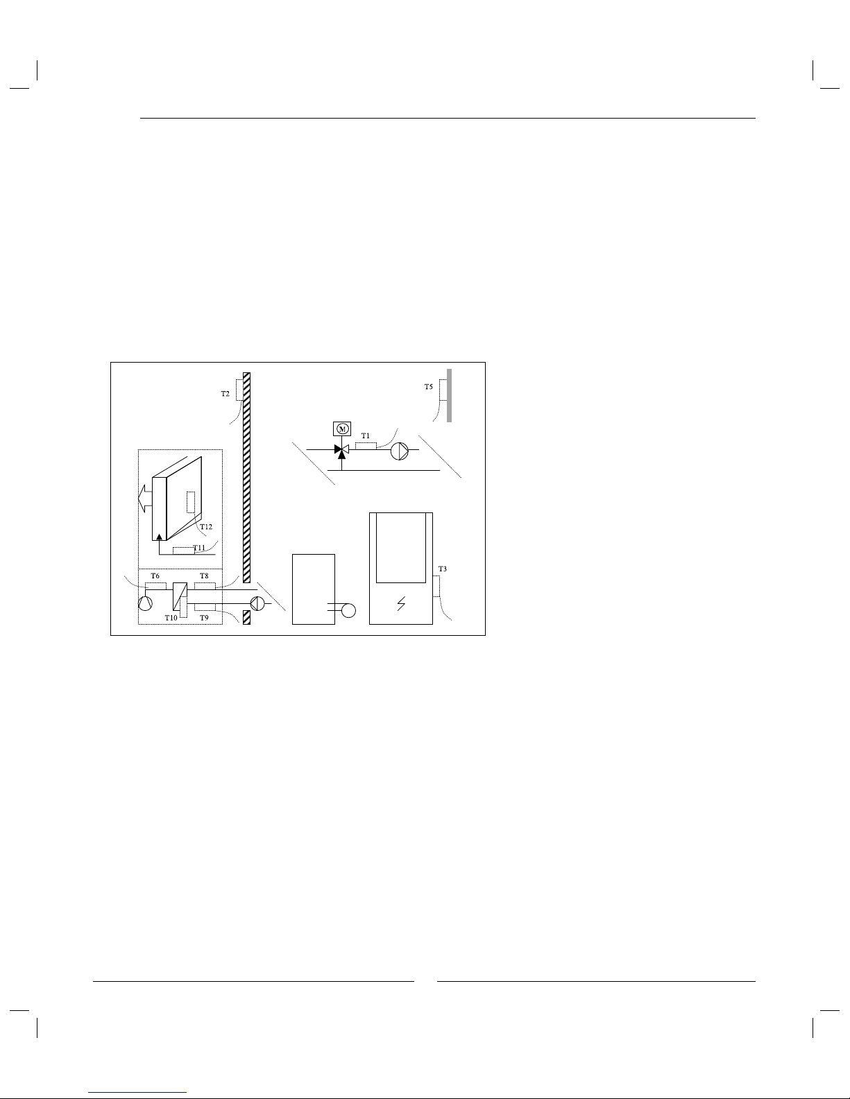
General
T1 Flow sensor
T2 Outdoor sensor
T3 Hot water sensor (if hot water heater is installed)
T5 Room sensor
T6 Sensor compressor temperature
T8 Sensor heat transfer fluid out
T9 Sensor heat transfer fluid in
T10 Sensor condenser temperature
T11 Sensor refrigerant temperature evaporator
T12 Sensor air temperature evaporator
Location of the temperature sensors
Optima Electric/oil-
fi red boiler
Hot water
heater
Page 11
11
General
In Rego 800 the different circuit boards are connected by a communications cable, CANbus. CAN is an abbreviation of Controller Area Network
and is a two wire system for communication between the microprocessor
based modules/circuit boards. These are connected in series.
The heat pump has one circuit board (IOB circuit board). The accessor y
unit electric/oil-fi red boiler has one circuit board (IOB circuit board).
Other circuit boards (CPU, PSU and IOB circuit boards) are in the control
cabinet.
Suitable cable for external laying (connection between the circuit
boards) is cable ELAQBY 2x2x0.6. The cable must be twisted pair and
screened. The screen must only be earthed at one end and to the chassis
(not to a circuit board). Maximum cable length is 20 m.
The CANbus cable must not be laid alongside power supply cables. It may
be laid alongside sensor cables.
In the connection area of the heat pump the external CANbus cable must
be laid so that it does not come into contact with high current connections
(230/400V).
The connection between the circuit boards is by four wires since the
12V-supply between the circuit boards must also be connected. The circuit
boards have markings for both the 12V and CANbus connections.
Warning
Do not mix up the 12V and CANbus connections! If 12V (or other
incorrect voltage) is supplied to the
CANbus contacts the processors in the
CANbus are destroyed. Check, therefore, that the four cables are connected
to the contacts with the corresponding
marking on the circuit boards in the
accessory unit and the heat pump.
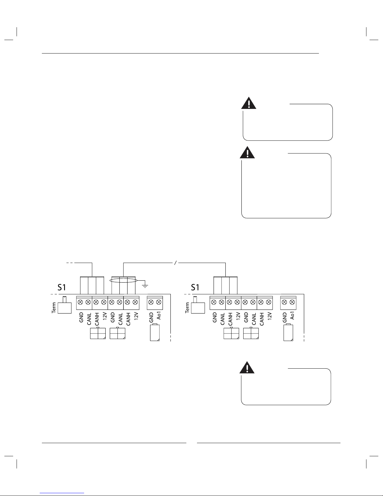
Switch S1
The switch is used to mark the start and end of a CANbus loop. This
means that the IOB circuit board in the heat pump and the accessory unit
circuit board must be terminated using S1, which must be in position Ter m.
Ensure that this is the case and that all other switches are in the opposite
position.
CANbus
Warning
The CANbus cable must be screened
and laid separately from the power
cable to prevent interference in the
CANbus communication.
Screen
Warning
Handle the circuit boards with great
care. They are sensitive to ESD (Electrostatic discharge), which can cause
faults in electronic components.
Page 12

12
General
Detailed pictures connection area
Optima 600 - 1100
Optima 1400 - 1700
High pressure
pressostat
Service
connection
Compressor
Expansion valve
Four-way valve
Service
connection
Non-return
valve
Low pressure
pressostat
Drying fi lter
Sight glass
Condenser
Venting nipple
High pressure switch Drying fi lter Sight glass Service
connection
Service
connection
Compressor
Condenser
Expansion valve
Four-way valve
Non-return
valve
Low pressure
pressostat
Suction
accumulator
Page 13
13
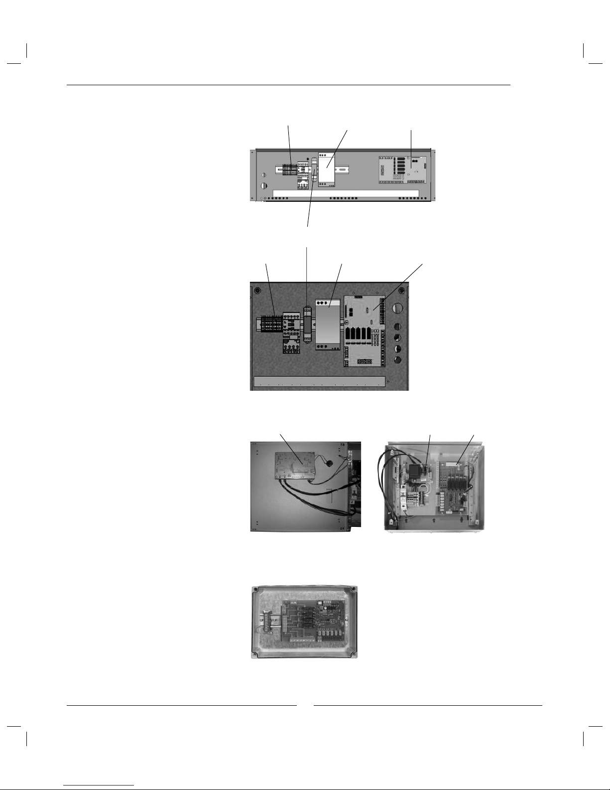
Accessory unit electric/
oil-fi red boiler
General
Control cabinet
IOB board
PSU board
CPU board (mounted on the
inside of the door)
Electrical cabinet Optima
600-1100
(above the compressor)
Electrical cabinet Optima
1400-1700
(left-hand side of heat pump)
Electrical
connections
Soft starter IOB card
Electrical
connections
Soft starter IOB card
Phase sequence relay
Page 14
14
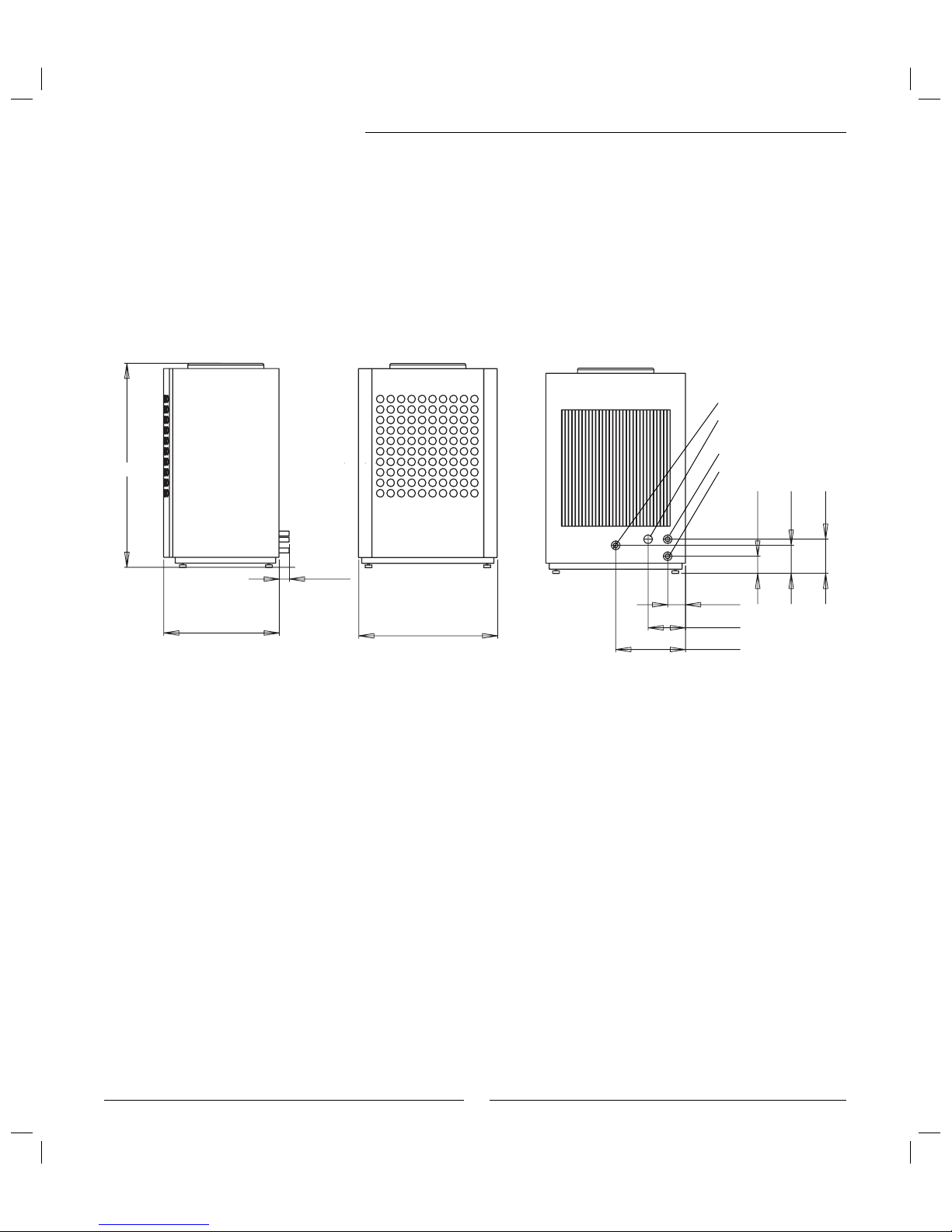
Dimensions, clearance and plumbing connections
Dimensions, clearance and plumbing connections
Front
Left-hand side
To heating system
(Hose 1 inch internal thread)
Draining, plastic pipe 32 mm
Back
Electric lead-ins
640
1190
60
820
411
220
105
101
165
201
Optima 600-1100
Required installation space for the heat pump.
Minimum distance from the pump to the wall is 300 mm.
Minimum distance in front of the pump 1000 mm, to the sides 500 mm.
If a roof is installed it must be positioned at least 1.5 m above the heat
pump to avoid the recirculation of cold air.
From the heating system
(Hose 1 inch internal thread)
Page 15

15
Optima 1400-1700
Dimensions, clearance and plumbing connections
Required installation space for the heat pump.
Minimum distance from the pump to the wall is 300 mm.
Minimum distance in front of the pump 1000 mm, to the sides 500 mm.
If a roof is installed it must be positioned at least 1.5 m above the heat
pump to avoid the recirculation of cold air.
705
920
1660
From above
Right-hand sideBack
1 Heat transfer fl uid out external G25
2 Heat transfer fl uid in external G25
3 Drainage external G25
Right
Left
Front
1
2
3
Page 16

16
Dimensions, clearance and plumbing connections
Control cabinet, Accessory unit
electric/oil-Þ red boiler
The units must be wall mounted indoors close to the other indoor components.
Control cabinet
Accessory unit
Double-shelled hot water heater
See the documentation for the hot water heater. See also Connection
principles.
Fit the particle Þ lter
The task of the particle fi lter is to fi lter out dir t before it can enter the heat
pump. Consequently, the particle fi lter supplied with the heat pump should
always be fi tted on the incoming hot pipe. It should be fi tted as close to the
heat pump as possible and be horizontal.
Page 17

17
Connecting to the heating system
Connecting to the heating system
Flushing the heating system
It is important that all previously mentioned preparations have been
carried out before the heat pump is connected to the heating system. Also
ensure the pipe system has been well fl ushed before it is connected to the
heat pump. Flushing protects the heat pump from contamination.
The heat pump is a part in a heating system. Faults in the heat pump can
be caused by poor water quality in the radiators/underfl oor coils or that air
is penetrating the system continuously. Oxygen causes corrosion products
in the form of magnetite and sediment. Magnetite has a grinding effect on
the heat pump pumps, valves and components with turbulent fl ows such
as the condenser. Heating systems which require regular fi lling or where
the heating water is not clear when drained, requires remedial measures
before the installation of a heat pump, for example the heating system must
be fi tted with fi lters and vents. Do not use any water treatment additives
except agents for raising the pH level.
An intermediate heat exchanger is sometimes necessary to protect the
heat pump.
Connecting the heat pump to the heating
system
Use the information in section Dimensions, clearances and plumbing connections to connect the different parts of the heating unit.
In addition, to avoid vibration transfer between the heat pump and the pipe
system we recommend fi tting fl exible hoses at the inlet and outlet of the
heat pump.
Between the heat pump and the house we recommend 28 mm copper
pipe for lengths of less than 20 metres. The pipes must be insulated with a
material, such as Armafl ex, which cannot absorb moisture. Venting valves
must be provided on the pipes. Short outdoor pipes reduce heat losses.
Connecting three-way valve
Connect a 3-way valve if the hot water heater is to be included. A description how to connect a ESBE type three-way valve is given to the right.
The ESBE 3-way valve must be installed on the return line according to the
system solution. Some 3-way valves are designed to be located on the fl ow
line. If such a valve is used, install it on the fl ow line
Heat carrier pump G2
Connect G2 and the shut off valves. The fl ow across G2 must be set slightly
lower than the fl ow across G1.
Note
Only qualifi ed installers may carry out
the installation. The installer should
observe applicable r ules and regulations and recommendations from the
supplier.
Port A:
From hot water
heater.
Port B:
From heating
system
Port AB: To heat pump
Page 18

18
Q Shut off valve
Q Safety valve outlet
Q Control valve with motor
T Temperature sensor
E Double-shelled water heater with electric element
E Oil-Þ red boiler/Electric boiler
E Heat pump
C Expansion tank
W Filter/Screen
G Pump
G Fan
W Filter valve
W Domestic hot water
W Inlet/outlet
Pipe (Arrow denotes direction of ß ow)
Crossing pipes
T-piece
Optima with electric/oil-fi red boiler and hot water heater
Connection principles
The principle is based on liquid condensation and additional heat from an electric/oil-fi red boiler using a mixing valve.
The control unit controls the heat pump using the outdoor sensor T2 and the return sensor T1 according to the set heat
curve. When the heat pump is unable to meet the heating requirements, the electric/oil-fi red boiler starts automatically and together with the heat pump provides the required temperature. Hot water is prioritised and controlled by a
sensor, T3 in the heater. While the water is heating in the hot water heater, the heating system from the heat pump is
disconnected temporarily through a three-way valve. If the electric/oil-fi red boiler is in operation it provides the required
temperature to the heating system. When the hot water is heated the heat pump continues the heat production.
Hot water mode when the heat pump is not operating:
The heat pump stops automatically at outdoor temperatures below approximately -10ºC and cannot then produce hot
water. The electric element in the hot water heater (IVT 300/160) is then automatically activated by the control unit and
the hot water heater will thus maintain a high temperature. The temperature is adjustable using the thermostat on the
electric element.
Connected sensors:
T1 Flow sensor
T2 Outdoor sensor
T3 Hot water sensor (accessor y)
T5 Room sensor (accessory)
T8 Sensor heat transfer fl uid out
T9 Sensor heat transfer fl uid in
Connecting to the heating system
Mixing valve
Three-way valve
Hot water
Cold water
Particle
fi lter
Heating
system
Outdoor sensor
Room sensor,
accessory
Note
If a hot water heater is not included,
connect the cold and hot water pipes to
the electric/oil-fi red boiler.
Page 19

19
Connecting to the heating system
Warning
The hot water heater must always be
fi lled and pressurised before the heating system is fi lled.
The installation must not, under any
circumstances, be switched on without
water.
Venting nipple (only Optima 600-1100)
Optima 600-1100
Filling the heating system
After fl ushing the heating system the hot water heater must be fi lled with
water. The heating system is then fi lled.
This is what to do:
1. Open and close the tap between the cold water system and the heating
system in short time inter vals.
2. Read the pressure on the expansion tank pressure gauge.
3. Vent the system and refill to the correct pressure.
Page 20

20
Connecting to the power supply
Check that cables and printed circuit boards are intact. High and low
current cables should be routed separately in order to avoid interference
on the sensors.
The heat pump control unit is mounted in the control cabinet. Connect
additional heat equipment to the accessory unit. The compressor, fan,
sensors, pressure switches, etc. are connected to the heat pump’s junction
box. The cable between the control cabinet, accessory unit and heat
pump’s electrical box is routed according to the diagram External connec-
tions diagram.
The following sensors are to be connected during installation: T1 Flow
sensor, T2 Outdoor sensor, T3 Hot water sensor (accessory), T5 Room sensor
(accessory).
Install the fl ow sensor T1 in direct contact with the fl ow pipe.
Accessories
Hot water sensor T3
When IVT 300/160 is used T3 is already installed on the heater. The sensor
is connected according to External connections Control cabinet. Note that
300/160 must be supplemented with a 6 kW electric element, see separate
guide.
Room sensor T5
The room sensor is placed centrally in the house and is connected
according to External connections Control cabinet.
Soft starter
The compressor can be equipped with a soft starter to reduce the inrush
current. The soft star ter is fi tted on the heat pump and is connected
according to Wiring diagram Optima.
Heating cable
A drainage pipe from the heat pump’s drip collector may need to be fi tted
with a heating cable. See Accessories under What the shipment includes?
for information about lengths. The heating cable is according to External
connections Heat pump.
Connecting to the power supply
Warning
Handle the circuit boards with great
care. They are sensitive to ESD (Electrostatic discharge), which can cause
faults in electronic components.
Page 21

21
Safety switch and earth-fault breaker
Safety switch
All heating installations must be isolated by a safety switch.
Earth-fault breaker
If the heating installation is to be connected across an earth-fault breaker
then a separate earth-fault breaker for the heating installation is recommended. Comply with applicable regulations.
Emergency operation
The heat pump is equipped with emergency operation which means that
the additional heater takes over the heat production in the event of faults in
the control unit. Read more about emergency operation in the User Guide.
On the OPB circuit board there is switch, S4, which can be activated for
emergency operation, see under heading Wiring diagram Accessory unit.
Connecting to the power supply
Page 22

22
Wiring diagram Optima 600-1100
Connecting to the power supply
B1: Phase sequence monitor
E3: Crankcase heating
E4: Any heating cable
F1: Miniature circuit breakers
G3: Fan
K1: Contactor compressor
M1: Compressor
MB2: Motor cut-out compressor
Q3: Four-way valve
R1: Soft starter
S1: Termination switch
HP: High pressure switch
LP: Low pressure switch
T6: Compressor hot gas
T8: Heat transfer ß uid out
T9: Heat transfer ß uid in
T10: Condenser
T11: Evaporator temperature
T12: Air intake
To Control cabinet
Blue
Brown
Black
G3
S1 must be in "Term" position on
the Þ rst and last circuit board in
the CANbus loop.
1) Strap
Page 23

23
Connecting to the power supply
Wiring diagram Optima 1400-1700
B1: Phase sequence monitor
E3: Crankcase heating
E4: Any heating cable
F1: Miniature circuit breakers
G3: Fan
K1: Contactor compressor
M1: Compressor
MB2: Motor cut-out compressor
Q3: Four-way valve
R1: Soft starter
S1: Termination switch
HP: High pressure switch
LP: Low pressure switch
T6: Compressor hot gas
T8: Heat transfer ß uid out
T9: Heat transfer ß uid in
T10: Condenser
T11: Evaporator temperature
T12: Air intake
U1: Brown
U2: Red
V1: Blue
V2: Grey
W1: Black
W2: Orange
L1: Black
L2: Brown
L3: Grey
PE: Yellow green
Diagram fan motor M2
High speed
Optima 1300
Low speed
Optima 1000
To Control cabinet
S1 must be in "Term" position on
the Þ rst and last circuit board in
the CANbus loop.
1) Strap
Page 24

24
Wiring diagram Control cabinet
Connecting to the power supply
F1: Miniature circuit-breaker
F2: Miniature circuit-breaker
G1: Pump for heating system
G2: Heat carrier pump
L1: LED operation/alarm
Q1: Any three-way valve
S1: Termination switch
S2: On/Off
S3: Switch emergency operation
K: Any additional heat WH
T1: Flow sensor
T2: Outdoor sensor
T3: Any hot water sensor
T5: Room sensor, accessory
To Heat pump
To Accessory unit
Open
Strap
S1 must be in "Term" position on
the Þ rst and last circuit board in
the CANbus loop.
Page 25

25
Wiring diagram Accessory unit
Connecting to the power supply
Open
Strap
Close
To Control cabinet To Control cabinet
Do1: Starting additional heat (oil-Þ red boiler/electric element) heating system.
PLEASE NOTE: Maximum relay output load, 1800W resistive, 600W inductive,
cos
ϕ >0,4. At greater loads, an intermediate relay must be installed, not
included.
H1: Any additional heat alarms. Closing during operation causes alarm Fault on
additional heat heating system.
Q2: Mixing valve.
S4: Switch emergency operation (starting oil-Þ red boiler/electric element)
Function Emergency operation:
Switch S3 on the control cabinet starts the heating system’s pump G3 and
heat carrier pump G2.
Switch S4 on the accessory unit is used for starting the oil-Þ red boiler or the
electric element.
If the emergency operation function is to be used, the pre-installed cables
from switch S4 must be connected to the OPB circuit board according to wiring
diagram (L and Do1).
NOTE! An electric element must have overheat protection with built-in
thermostat.
S1 must be in "Term" position on
the Þ rst and last circuit board in
the CANbus loop.
Page 26

26
External connections diagram
Connecting to the power supply
Control cabinet
Accessory unit electric/
oil-fi red boiler
Heat pump
Open
Open
E4: Heating cable in draining pipe, accessory
G1: Pump for heating system
G2: Heat carrier pump
Q1: 3-way valve, accessory
Q2: Mixing valve, accessory
K: Contactor any electrical additional heat in the hot water heater
Do1: Starting additional heat (oil-Þ red boiler/electric element). PLEASE NOTE:
Maximum relay output load, 1800W resistive, 600W inductive, cos ϕ >0,4.
At greater loads, an intermediate relay must b installed, not included.
S4: Switch emergency operation. Pre-installed switch connected by installer if
the function is required.
H1: Any additional heat alarm
T1: Flow sensor
T2: Outdoor sensor
T3: Hot water sensor, accessory
T5: Room sensor, accessory
Optima 600-1100, Optima 1400-1700
Close
NOTE! If the emergency operation
function is to be used, the electric
element’s overheat protection must
have a built-in thermostat.
Safety switch not included.
Optima 600/900/1100: 10A
Optima 1400/1700: 16A
Page 27

27
External connections Heat pump
Power supply:
Connect to terminals L1, L2, L3, N and PE.
CANbus:
Communication cable between the circuit boards in the control
cabinet, heat pump and accessory unit. Connect to terminals GND,
CANL, CANH and 12V. See more under section CANbus.
E4, Heating cable:
The drainage pipe from the heat pump’s discharge water vessel may
need to be fi tted with a heating cable. The heating cable is connected
to terminals Do4, N. See section Accessories.
Warning
Connecting to the power supply
Note
S1 must be in position Term here and
on the accessory unit board.
To Control cabinet
Do not mix up the 12V and CANbus connections! If 12V (or other
incorrect voltage) is supplied to the
CANbus contacts the processors in the
CANbus are destroyed.
Page 28

28
Connecting to the power supply
External connections Control cabinet
Power supply:
Connect to terminals L1, L2, L3, N and PE and then further feed
to the heat pump. Connect further supply to the accessor y unit on
terminals 1, N and PE.
CANbus:
Communication cable between the circuit board in the control
cabinet, heat pump and optional unit. Connect to terminals GND,
CANL, CANH and 12V. See more under section CANbus.
T1, Flow sensor: Connect to terminals Ai1 and GND.
T2, Outdoor sensor: Connect to terminals Ai2 and GND.
T3, Hot water sensor: Accessory. Connect to terminals Ai3 and GND.
T5, Room sensor: Accessory. Connect if room sensor infl uence is
required. Connect to terminals Ai4 and GND.
G1, Heating system pump: Connect to terminals Do1 and N.
G2, Heat carrier pump: Connect to terminals Do2 and N.
Q1, Three-way valve: Accessory. Connect to terminals L, Do3 (Open)
and N.
K: Any contactors for the hot water heater’s electric element can be
connected to terminals Do4 and N.
Open
To Heat pump
To Accessory unit
Warning
Strap
Do not mix up the 12V and CANbus connections! If 12V (or other
incorrect voltage) is supplied to the
CANbus contacts the processors in the
CANbus are destroyed.
Page 29

29
Connecting to the power supply
External connections Accessory unit
Power supply:
Connected to terminals L, N and PE.
CANbus:
Communication cable between the circuit boards in the control
cabinet, heat pump and accessory unit. Connect to terminals GND,
CANL, CANH and 12V. See more under section CANbus.
Q2, Mixing valve:
Connect to terminal Do2 (Open), N (Zero) and Do3 (Close).
H1, Any additional heat alar m:
Closing during operation causes alarm Fault on additional heat for
heating system.
Do1, Starting additional heat:
Connect the cable to electric or oil-fi red boiler contactor. Only connect
when a hot water heater is included. NOTE: Maximum relay output
load, 1800W resistive, 600W inductive. At greater loads, an
intermediate relay must be installed, not included.
Warning
Do not mix up the 12V and CANbus connections! If 12V (or other
incorrect voltage) is supplied to the
CANbus contacts, the processors in the
CANbus are destroyed.
To Control cabinet
Strap
Open
Close
Note
S1 must be in position Term here and on
the IOB circuit board in the heat pump.
Page 30

30
Installer and service menu (I/S)
Warning
The installer and service menu (I/S) is
only for installers. Under no circumstances may the user access this level.
Installer and service menu
First read aboutCommissioning.
As the installer you have your own section of menus for settings, e.g. for
commissioning and maintenance.
The User Guide for the heat pump contains a complete description of how
the control panel functions and of all customer functions under Menu and
Advanced menu. Read it before you start.
A four digit access code is required to access the I/S menus.
This is what to do:
1. Press the menu dial for approximately five seconds to get to Advanced
menu.
2. Select Access level.
3. Enter the four digit access code using the menu dial and press the
menu dial to confirm. The access code is the present date given as two
digits for the month and two digits for the date (for example 0920).
Access = service is shown in the display. Press the dial to get to Menu.
Under Menu there are now both customer functions and I/S functions.
To reach Advanced menu press the menu dial for approximately five
seconds.
4. Return to customer level by selecting Access level in Advanced menu
and enter 0000 as access code.
The control unit automatically returns to customer level after approxi-
mately 120 minutes.
Page 31

31
Menu overview
Here you fi nd the upper levels for all functions under Menu and Advanced
menu. All setting functions can also be found in the table Factory settings,
see Technical information.
Menu overview
Menu
Fast restart of heat pump?
I/S
Start up
Setting the clock I/S
Connected extra sensors I/S
Manual operation I/S
Additional heat options I/S
Language I/S
Correct sensor I/S
Fan defrost interval I/S
Fan defrost time I/S
Forced defrost I/S
Block crankcase heater at high outdoor temperature I/S
Anti-jamming mode time I/S
Alarm buzzer signal length I/S
T1 Set point value maximum I/S
Display I/S
Room temperature setting (T5)
K
Temperature increase/decrease (no T5)
K
Temperature increase/decrease
settings (no T5)
I/S
Limit value for V or H
Much colder/warmer, change
Colder/warmer, change
Temperatures
K
Page 32

32
Menu overview
Advanced menu
Temperature
Heating system temperature K
Room sensor settings (T5) K
Time limited settings K
Heating season K
Heating, maximum operating time at hot water requirement K
Shut down protection, change over hot water to heating I/S
Compressor working area settings I/S
Hot water
Extra hot water K
Hot water peak K, I/S
Hot water temperature K, I/S
Time control hot water K
Hot water additional heat I/S
Temperatures
Shows temperatures, inputs, outputs
Correct sensor
I/S
Defrost settings
T12 - T11 settings I/S
Maximum outdoor temperature I/S
T11 Maximum temperature I/S
Maximum time I/S
Delay after compressor start I/S
Minimum time between defrosts I/S
Compressor pressure equalisation time I/S
4-way valve pressure equalisation time I/S
Forced defrost I/S
Heating cable time after defrost I/S
Fan defrost
Timers
Shows timers K, I/S
Additional heat settings
Start delay I/S
Time control additional heat I/S
Additional heat options I/S
Connected electrical capacity (shows present value) I/S
Page 33

33
Menu overview
Setting the clock
Set date
Set time
Alarm
Alarm log K, I/S
Alarm history I/S
Warning log I/S
Access level
K, I/S
Return to factor y settings
K, I/S
Deactivate alarm buzzer
K
Program version
K, I/S
Page 34

34
Commissioning
Commissioning
Before commissioning the heating system must be fi lled up and completely
vented. Check that there are no leaks.
As many radiators as possible should be fully open when connecting to an
existing water system. When connecting to an underfl oor heating system
at least half of all the fl oor coils should be open. When connecting to a
fan-assisted radiator system the fans are started fi rst and then the taps on
the fan-assisted radiators are opened fully.
Start the heat pump
1. Connect the mains and press the ON/OFF switch on the control panel.
A language selection window is shown.
2. Start by selecting the language to be applied to the menu windows.
The selected language automatically becomes the factory setting, that
is, is not changed by Return to factory settings. To change language
go to Language under Start up. Available: Dansk, Deutsch, English,
Français, Norsk, Suomi, Svenska,
Čeština.
3. Select Setting the clock.
Select Set date and adjust the date (yy-mm-dd) if it is not correct. Select
Set time to adjust the time if it is not correct.
4. Activate the installer and service menu, see Installer/service menu.
Start up
When you have entered the access code and are in Menu select the
function Start up.
All functions for carr ying out the basic settings in the heating installation
are gathered in the start up menu. Carry out/go through these in turn.
Setting the clock
See Start the heat pump.
Page 35

35
Connected extra sensors
The control unit senses which extra sensors (T3 hot water, T5 room sensors) have
been installed and displays which are acknowledged when you select Connected
extra sensors.
Manual operation
Make a check of all the functions before you commission the heating installation.
You can manually start and stop the pumps and valves from the menu Manual
Operation. Select Yes to activate.
NOTE! The function is deactivated by selecting No in Manual Operation.
Additional heat options
Additional heat only blocks the start of compressor and fan. Heating and hot water
is supplied via the additional heater.
Block additional heat blocks the additional heat function, but not during alarm
mode, hot water peak, extra hot water or operation with additional heat only.
NOTE! Normally this is not recommended.
Language
This allows you to change the language to one other than that selected when the
heat pump was fi rst star ted. The selected language automatically becomes the
factory setting, that is, is not changed by Return to factory settings.
Correct sensor
All sensors can be corrected here. The correction value is stated directly in °C.
Normally one should avoid correcting a sensor. The value that is given without
correction is most often the correct one. Correction of maximum 5ºC up or down
is possible.
Fan defrost interval and Fan defrost time
Because weather conditions vary from place to place some factory settings for
defrosting may need adjustment. This particularly applies to locations with high
humidity where there is a risk that the fan will ice up. Fan defrost means that
warm air is blown upwards through the fan.
The fan defrost function is active when the value Fan defrost interval is between
1 and 10, factory setting is 1. The value 1 states that fan defrosting will occur at
each ordinary defrosting. If the value is set to 3 then fan defrost occurs every third
defrost.
Select how long fan defrost should last. The factory setting is 1 min.
Min = 1 and max = 5.
The function is deactivated by selecting 0 in Fan defrost interval.
Temperature limit for fan defrost is set to -5ºC. No fan defrost occurs below this
temperature. This setting can be changed under Fan defrost in the Advanced menu.
Commissioning
Page 36

36
Forced defrost
Forced defrost is used to bypass the timer and temperature conditions for
defrost. Temperature T11 (refrigerant temperature evaporator) must be
below the set stop level for defrosting.
Block crankcase heater at high outdoor temperature
Checked by outdoor sensor T2. When the outdoor temperature exceeds
the set value the crankcase heating in the compressor is deactivated. The
crankcase heater is active when the compressor is idle and the outdoor
temperature is below the set value. Factory setting = 10ºC. Min = 5ºC and
max = 20ºC.
Anti-jamming mode time
At the set time each day the circulation pumps G1 and G2, three-way valve
VXV and fan are run for one minute each, provided that they have not
been in operation during the previous 24 hours. Factory setting = 2, which
means 02:00. Min = 0, max = 23.
Alarm buzzer signal length
In event of an alarm the alarm signal is sounded for the set time if the
signal is not deactivated. The factory setting is 1 minute, max setting is 10
minutes.
T1 Set point value maximum
T1 is set to max, that is 80°C, on delivery. The value may need to be
reduced if only underfl oor heating is used.
Display
The function affects the window contrast and brightness. On deliver y the
max setting 10 is set on both.
Alarm during start up
During start up there may be an alarm regarding Low temperature in
condenser. The cause is that the fi lled water is too cold (colder than +5ºC).
Check the sight glass inside the heat pump. Bubbles may appear in the
sight glass for a few minutes during start up. The bubbles should then
stop. If it bubbles continuously this is a fault symptom which is probably
due to insuffi cient refrigerant.
Sight glass
Commissioning
Page 37

37
Other settings
Go through the heating and hot water settings in the Menu and
Advanced menu and make the necessary changes. For example the
heat curve settings for underfl oor heating need to be lower than the
factory settings. Set appropriate V and H values.
Important points to check after
commissioning
For the installation to perform at its best, it is important to check
the fl ow on the hot side of the heat pump. Usually, the heat carrier
pump has a speed selector switch. This must be set correctly for the
pressure drop in the system. A recommended temperature dif ference
across the heat pump on the hot side is between 5 and 10ºC. The
nominal fl ows provided in Technical data provide a dif ference of 7ºC
in operating mode +7/45ºC. Check this by reading the sensors T9
(heat transfer fl uid in) and T8 (heat transfer fl uid out). These can be
found under Temperatures in the Advanced menu.
When commissioning is carried out at a low outdoor temperature
(below 0ºC) the temperature difference should be between 5ºC and
7ºC.
When commissioning is carried out at an outdoor temperature above
15ºC the temperature difference must be between 8ºC and 10ºC.
The fl ow through the heating system should be suffi cient to keep the
whole radiator warm and thereby increase the heat emitting surface.
This means that the fl ow temperature is kept low.
After testing, vent the heating system again and top up with cold water
if necessary. See Filling the heating system.
Commissioning
Page 38

38
Advanced menu
Extra hot water
Displays the remaining time for requested extra hot water.
Additional heat start
Displays the countdown of the timer for delay of additional
heat.
Mixing valve control delay
Displays the time that the mixing valve function is delayed
after the additional heat timer has counted down.
Alarm mode delay
Displays the remaining time until the additional heat is
activated when an alarm is triggered.
Compressor start
Displays the remaining time of compressor start delay.
Delay before defrost
Displays the remaining time before defrosting is permitted.
T12-T11 reached temperature difference
The heat pump regularly calculates the difference between
T12 and T11. The result is compared to the set point value
which is calculated based on actual outdoor temperature
and settings in Defrost settings\T12-T11 settings\Difference
at +10°C /0°C /-10°C. The timer starts when the dif ference
exceeds the set point value and, if it lies above the set point
value continuous defrosting is permitted to start when the
timer has counted down.
PLEASE NOTE: For defrosting to start the Delay before
defrost must have also counted down.
Defrost
Displays the remaining time before defrosting the evaporator.
Heating cable
Displays the remaining time for the heating cable in the
drainage pipe from the heat pump to be active.
Heating, maximum operating time at hot water requirement
Displays the remaining time before the maximum time in
heating mode is reached if there is a simultaneous hot water
requirement.
Hot water, maximum operating time at heating
requirement
Displays the remaining time before the maximum time
for hot water operation is reached if there is a simultaneous heating requirement.
Heating season change delay
Displays the remaining time until the heating season is
activated in the heat pump.
Blocking low pressure switch
Displays the time remaining when the low pressure
switch is blocked.
Blocking room sensor infl uence
Displays the time remaining when the room sensor is
blocked.
Hot water peak
Displays the remaining time for the hot water peak to be
active.
Hot water peak interval
Displays the time remaining to the next hot water peak.
Timers
There are a number of timers in the control unit.
The statuses for these are shown in the menu Timers.
Page 39

39
Alarm functions
Functions under Alarm:
Alarm log
Alarm history
Warning log
All alarms and warnings are described in the User guide.
At Customer level you have access to alarm information in the alarm log.
As installer you can also:
Delete the Alarm log
Read information in Alarm history
Read information in Warning log
Delete the Warning log
Alarm histor y
Alarm information
Alarms are stored in chronological order. Turn the menu dial to read off all
information about the most recent alarm, continuing to turn will show the
previous alarms.
Alarm information consists of a heading and then detailed information
about the time, temperatures of all sensors and status for each output when
the alarm occurred.
Warning log
The alarm log stores alarms in chronological order.
Deleting Warning log and Alarm log can be appropriate when commissioning has been completed.
Advanced menu
Page 40

40
Technical information
Technical information
Factory settings
The table displays the factory values (F value) of the settings that you, as a customer,
(K) can change via the customer menus Menu and Advanced menu. The functions of
Installer/Service level (I/S) under Menu and Advanced menu in the table are accessed by
the installer after changing the access level.
Menu
Level F value
Fast restart of heat pump?
I/S No
Start up
--"--\Setting the clock
--"--\ --"--\Set date I/S
yy-mm-dd
--"--\ --"--\Set time I/S
hh:mm:ss
--"--\Connected extra sensors
--"--\ --"--\T3 acknowledged (T3) I/S No
--"--\ --"--\T5 acknowledged (T5) I/S No
--"--\Manual operation I/S No
--"--\Additional heat options
--"--\ --"--\Additional heat only? I/S No
--"--\ --"--\Block additional heat? I/S No
--"--\Language I/S Selected
--"--\Correct sensor I/S 0
--"--\ Fan defrost interval I/S 1 time
--"--\Fan defrost time I/S 1,0 min
--"--\Forced defrost I/S No
--"--\Block crankcase heater at high outdoor
temperature
I/S 10,0ºC
--"--\Anti-jamming mode time I/S 02:00
--"--\Alarm buzzer signal length I/S 1 min
--"--\T1 Set point value maximum I/S 80ºC
Menu
Level F value
--"--\Display
--"--\ --"--\Contrast I/S 10
--"--\ --"--\Brightness I/S 10
Room temperature setting (T5)
K 20,0ºC
Temperature increase/decrease (no T5)
K=
Temperature increase/decrease settings (no T5)
--"--\Limit value for V or H I/S 10ºC
--"--\Much colder/warmer, change I/S 8%
--"--\Colder/warmer, change I/S 3%
Extra hot water
K0 h
Page 41

41
Technical information
Advanced menu
Level F value
Temperature
--"--\Heating system temperature
--"--\ --"--\Heat curve K
V=20,0ºC,
H=55,2Cº
--"--\ --"--\ Hysteresis
--"--\ --"--\ --"--\Maximum K 16,0ºC
--"--\ --"--\ --"--\Minimum K 4,0ºC
--"--\ --"--\ --"--\Time factor K 10
--"--\Room sensor settings (T5)
--"--\ --"--\Room temperature setting K 20,0ºC
--"--\ --"--\Room sensor infl uence
--"--\ --"--\ --"--\Change factor K 5,0
--"--\ --"--\ --"--\Blocking time K 4 h
--"--\Time limited settings
--"--\ --"--\Time control heating
--"--\ --"--\ --"--\Day and time K Off
--"--\ --"--\ --"--\Change in temperature K -10ºC
--"--\ --"--\Holiday
--"--\ --"--\--"--\Date K Off
--"--\ --"--\--"--\Change in temperature K -10ºC
--"--\Heating season
--"--\ --"--\Heating season limit K 18ºC
--"--\ --"--\Delay K 4 h
--"--\--"--\Direct start limit K 10ºC
--"--\Heating, maximum operating time at hot
water requirement
K 20 min
--"--\Shut down protection, change over hot
water to heating
I/S 300 s
Advanced menu
Level F value
Hot water (T3)
--"--\Extra hot water
--"--\ --"--\Number of hours K 0
--"--\ --"--\Stop temperature K 65,0ºC
--"--\Hot water peak
--"--\ --"--\Interval K 0 days
--"--\ --"--\Start time K 03:00
--"--\ --"--\Stop temperature I/S 65,0°C
--"--\Hot water temperature
--"--\ --"--\T8 Stop temperature hot water I/S 59,0°C
--"--\ --"--\In compressor mode
--"--\ --"--\ --"--\T3 Start temperature I/S 49,0°C
--"--\ --"--\ --"--\T9 Stop temperature I/S 54,0°C
--"--\ --"--\In additional heat only mode
--"--\ --"--\ --"--\T3 Stop temperature I/S 56°C
--"--\ --"--\ --"--\T3 Hysteresis I/S 1,0°C
--"--\ --"--\Hot water, maximum operating time at
heating requirement
K 30 min
--"--\Time control hot water K Of f
--"--\Additional heat in water heater
--"--\--"--\ T3 Start value of fset I/S 5,0ºC
--"--\--"--\ T3 Hysteresis I/S 2,0ºC
Temperatures
--"--\Correct sensor I/S 0,0
Defrost settings
--"--\T12 - T11 settings
--"--\ --"--\Time for reached temperature
difference
I/S 60 s
--"--\ --"--\Difference at +10°C I/S 12ºC
--"--\ --"--\Difference at 0°C I/S 8ºC
--"--\ --"--\Difference at -10°C I/S 6ºC
--"--\Maximum outdoor temperature I/S 13ºC
--"--\T11 Maximum temperature I/S 20ºC
--"--\Maximum time I/S 15 min
--"--\Delay after compressor start I/S 10 min
Page 42

42
Technical information
Advanced menu
Level F value
--"--\Minimum time between defrosts I/S 30 min
--"--\Compressor pressure equalisation time I/S 0 s
--"--\4-way valve pressure equalisation time I/S 0 s
--"--\Forced defrost I/S No
--"--\Heating cable time after defrost I/S 15 min
--"--\Fan defrost
--"--\ --"--\Fan defrost interval I/S 1 time
--"--\ --"--\Fan defrost time I/S 1,0 min
--"--\ --"--\Temperature limit I/S -5ºC
Additional heat settings
--"--\Start delay I/S 60 min
--"--\Time control additional heat I/S Of f
--"--\Additional heat options
--"--\ --"--\Additional heat only? I/S No
--"--\ --"--\Block additional heat? I/S No
--"--\Mixing valve settings
--"--\ --"--\Mixing valve delay I/S 20 min
--"--\ --"--\Neutral zone I/S 1,0°C
--"--\ --"--\Running time extension
--"--\ --"--\ --"--\Increase signal extension I/S 1
--"--\ --"--\ --"--\Decrease signal extension I/S 1
--"--\ --"--\Additional heat maximum temperature
--"--\ --"--\ --"--\Mixing valve limitation start
temperature
I/S 47°C
--"--\ --"--\ --"--\Mixing valve force close I/S 48°C
--"--\ --"--\Limitation at temperature increase I/S Yes
--"--\ --"--\Limitation time I/S 20 s
Advanced menu
Level F value
Setting the clock
--"--\Set date K
yy-mm-dd
--"--\Set time K
hh:mm:ss
Alarm
--"--\Alarm log
--"--\ --"--\Delete alarm log? I/S No
--"--\Warning log
--"--\ --"--\Delete warning log? I/S No
Access level
K, I/S K (0)
Return to factor y settings
K, I/S No
Deactivate alarm buzzer
KNo
Page 43

43
Technical information
Dimensions
Control cabinet (WxDxH) mm 335x112x296
Accessory unit (WxDxH) mm 255x100x180
Control cabinet and accessory unit electric/oil-fi red boiler
Technical information
Output data at +7/35º and +7/45º are stated according to the European standard EN 14511.
1)
Dimensions excl. feet, supplied min 20 mm - max 30 mm depending on adjustment
Model IVT Optima 600 900 1100 1400 1700
Emitted/Supplied output at +7/35º kW 5.5 / 1.4 7.2 / 2.0 8.9 / 2.3 12.9 / 3.3 14.3 / 3.9
Emitted/Supplied output at +7/45º kW 5.1 / 1.7 7.0 / 2.4 8.6 / 2.8 12.5 / 4.0 14.1 / 4.7
Heat carrier fl ow nominal l/s 0.19 0.29 0.34 0.47 0.55
Internal pressure drop heat carrier kPa 5 6 7 7 8
Air fl ow m³/h 2200 2200 2200 5500 5500
Electrical consumption fan A 0.44 0.44 0.44 0.7 (400V N3) 0.7 (400V N3)
Electrical supply 400V 3N~ 50Hz
Fuse size AT 10 16
Compressor Scroll
Highest outgoing heat carrier temperature ºC 65
Refrigerant fi lling R-407C kg 2,5 2,6 2,7 3,4 3,5
HTF connection mm Hose 1 inch internal thread external G25
Defrost system Hot gas with four-way valve
Dimensions (WxDxH)
1)
mm 820x640x1190 920x705x1660
Weight kg 140 145 155 160 165
Colour Champagne
Outer casing Galvanised enamelled plate
Page 44

44
Technical information
Sensor table
The table shows all sensor resistance at different temperatures.
Sound levels
The table describes the sound levels stated in sound
pressure level.
Sound pressure level:
Sound pressure level is defi ned as the sound level, which
at an ear level of 1.8 metres, is perceived one metre from
the heat pump. Measured in a sound measurement room
without echo at an outdoor temperature of +7ºC and 50ºC
fl ow temperature.
Example:
When the heat pump is installed outside with free sound
propagation the sound level drops by 6dBa with each
doubling of distance.
Example Optima 600 Optima 1400
Distance Lp - ear (dBa) Lp - ear (dBa)
1 metre 53 59
2 metres 47 53
4 metres 41 47
8 metres 35 41
Heat pump
Sound pressure level
Lp - ear (dBa)
Optima 600 53
Optima 900 53
Optima 1100 53
Optima 1400 59
Optima 1700 59
Temperature (ºC) kΩ
-40 154.300
-35 111.700
-30 81.700
-25 60.400
-20 45.100
-15 33.950
-10 25.800
-5 19.770
0 15.280
5 11.900
10 9.330
15 7.370
20 5.870
25 4.700
30 3.790
35 3.070
40 2.510
45 2.055
50 1.696
55 1.405
60 1.170
65 0.980
70 0.824
75 0.696
80 0.590
85 0.503
90 0.430
Page 45

Page 46

IVT Industrier AB, Sweden
www.ivt.se | mailbox@ivt.se
 Loading...