

Page 1
TopPage
xxxxxxxxx
SERVICE MANUAL
No. XXXXXXXXXXXXX
SPLIT TYPE
ROOM AIR CONDITIONERS
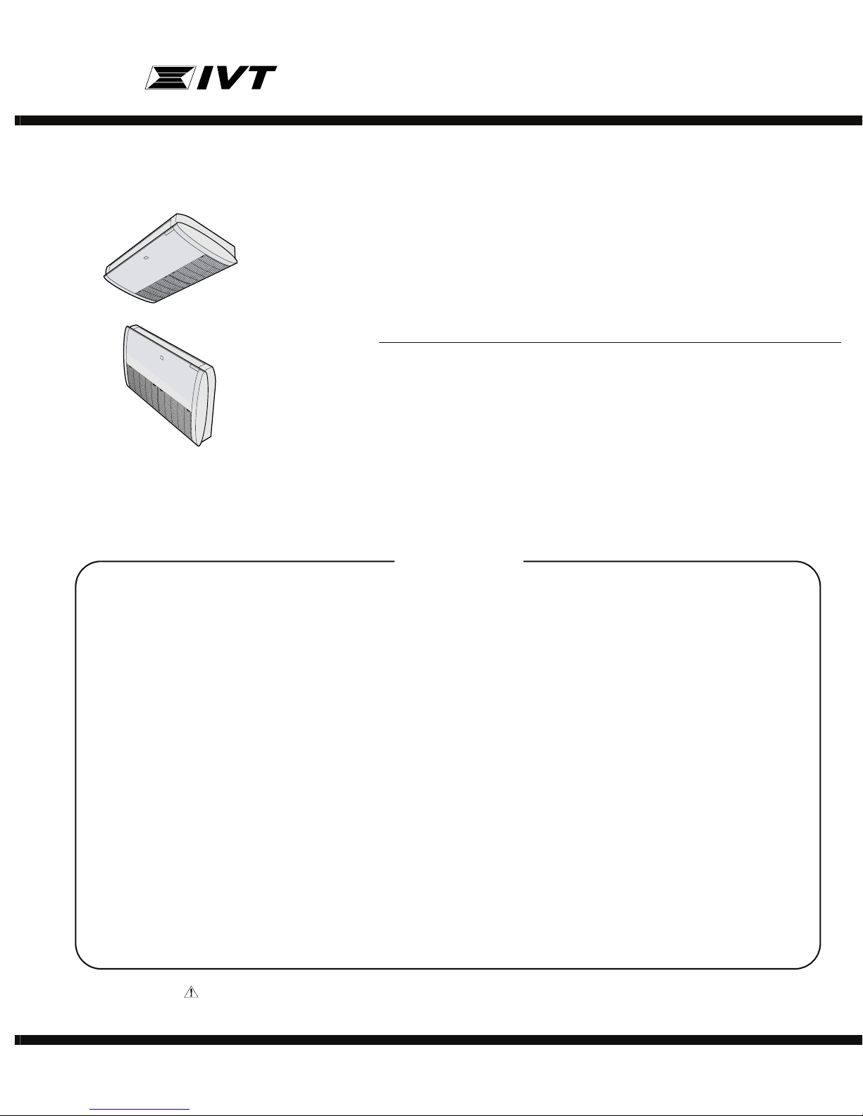
CEILING TYPE
MODELS
INDOOR UNIT
GS-XP12HR-N
In the interests of user-safety (Required by safety regulations in some
countries) the set should be restored to its original condition and only
parts identical to those specified should be used.
FLOOR TYPE
CONTENTS
CHAPTER 1. SPECIFICATION
[1] SPECIFICATION............................................ 1-1
[2] EXTERNAL DIMENSION............................... 1-2
[3] WIRING DIAGRM .......................................... 1-4
[4] ELECTRICAL PARTS .................................... 1-4
CHAPTER 2. EXPLANATION OF CIRCUIT AND OPERATION
[1] BLOCK DIAGRAMS....................................... 2-1
[2] MICROCOMPUTER CONTROL SYSTEM........ 2-3
[3] FUNCTION..................................................... 2-7
CHAPTER 3. TROUBLESHOOTING
[1] TROUBLESHOOTING GUIDE....................... 3-1
[2] THERMISTOR TEMPERATURE CHAR-
ACTERISTICS ............................................... 3-5
[3] HOW TO OPERATE THE OUTDOOR
UNIT INDEPENDENTLY................................ 3-5
OUTDOOR UNIT
AE-X12FR-N
CHAPTER 4. REFRIGERATION CYCLE
[1] FLOW FOR REFRIGERANT.........................4-1
[2] STANDARD CONDITION ..............................4-1
[3] TEMPERATURE AT EACH PART AND
PRESSURE IN 3-WAY VALVE ......................4-1
[4] PERFORMANCE CURVES...........................4-1
CHAPTER 5. DISASSEMBLING PROCEDURE
[1] DISASSEMBLY OF INDOOR UNIT...............5-1
[2] DISASSEMBLY OF OUTDOOR UNIT.........5-13
Parts Guide
Parts marked with " " are important for maintaining the safety of the set. Be sure to replace these parts with specified ones for maintaining the
safety and performance of the set.
This document has been published to be used for
after sales service only.
The contents are subject to change without notice.
Page 2

GSXP12HRN
GSXP12HRN
CHAPTER 1. SPECIFICATION
Service Manual
[1] SPECIFICATION
1. GS-XP12HR-N / AE-X12FR-N
MODEL INDOOR UNIT OUTDOOR UNIT
ITEMS GS-XP12HR-N AE-X12FR-N
Cooling capacity (Min. ~ Max.) kW 3.5 (0.9 - 4.0)
Heating capacity (Min. ~ Max.) kW 4.2 (0.9 - 6.0)
Moisture removal (at cooling) Liters/h 0.9
Electrical data
Phase Single
Rated frequency Hz 50
Rated voltage V 230
Rated current ✩
(Min - Max.)
Rated input ✩
(Min - Max.)
Power factor ✩ Cool % 87
Compressor Type Hermetically sealed rotary type
Refrigerant system Evaporator Louver Fin and Grooved tube type
Noise level (at cooling) High dB(A) 43 49
Fan system
Drive Direct drive
Air flow quantity (at cooling) High
Fan Centrifugal fan Propeller fan
Connections
Refrigerant coupling Flare type
Refrigerant tube size Gas, Liquid 1/2", 1/4"
Drain piping mm O.D φ 20
Others
Safety device Compressor: Thermal protector
Air filters Polypropylene net (Washable)
Net dimensions Width mm 1025 780
Net weight kg 31 37
NOTE: The condition of star "✩" marked item are ‘ISO5151’ : 1994(E), condition T1, Voltage 230V.
Cool A 4.5 (1.2 - 6.0)
Heat A 4.7 (1.3 - 7.0)
Cool W 900 (200 - 1300)
Heat W 970(180 - 1800)
Heat % 90
Model 5RS092XDF
Oil charge RB68A or FREOL ALPHA68M 320ml
Condenser Corrugate Fin and Grooved tube type
Control Expansion valve
Refrigerant (R410A) 1000g
De-lce system Micro computer controled reversed systems
Low dB(A) 35 Soft dB(A) 29 -
3
m
/min.
Low
Soft
Height mm 212 540
Depth mm 680 265
3
m
/min.
3
m
/min.
12.9 30.2
10.3 –
7.3 –
Fan motors: Thermal fuse
Fuse, Micro computer control
1 – 1
Page 3
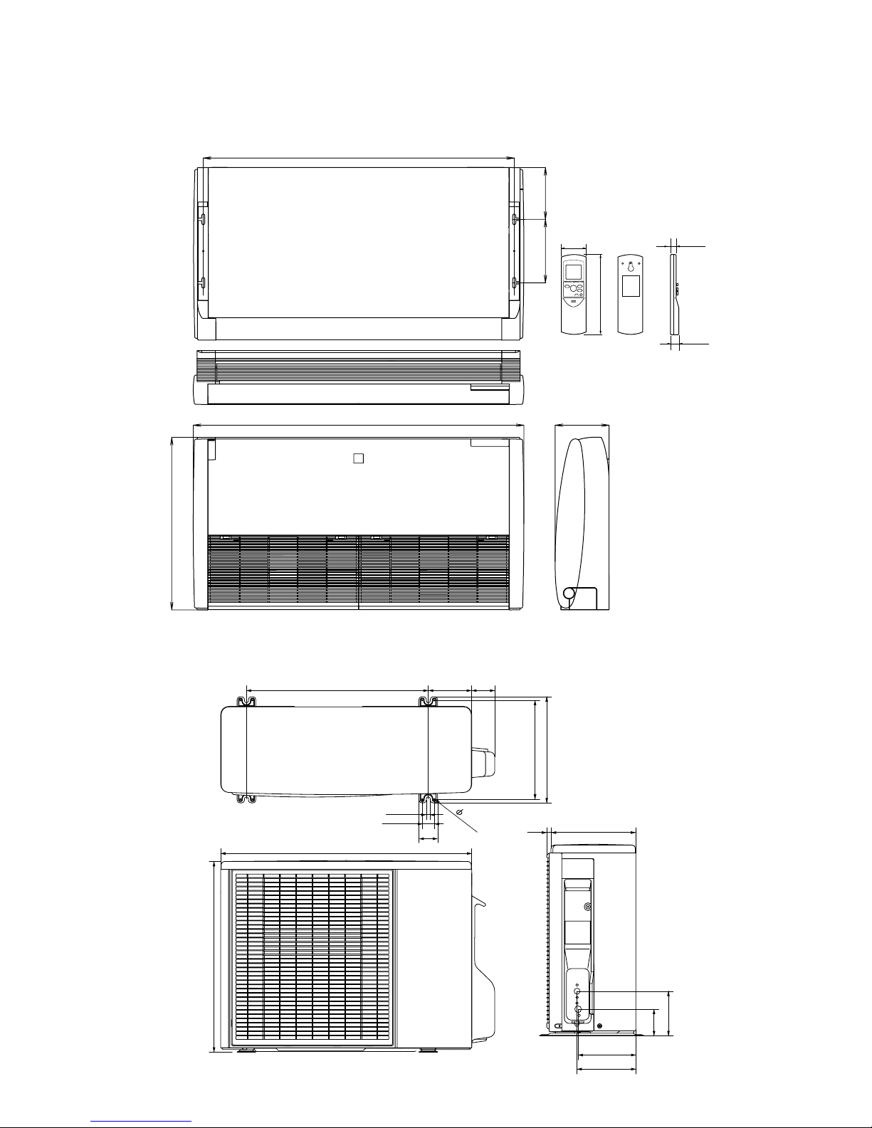
[2] EXTERNAL DIMENSION
1. GS-XP12HR-N / AE-X12FR-N
1.1. Indoor unit
GSXP12HRN
949
204
1.2. Outdoor unit
680
1025
250
58
INVERTERAIRCONDITIONER
212
175
CRMC-A442JBE0
R03(AAA)2PCS.
SHARPCORPORATION
18.5
22.0
540
540
780
12
37.5
72
135
299
324
4.5
58
14
265
165
167.5
136
81
1 – 2
Page 4
GSXP12HRN
1.3. Installation demensions
1.3.1 Ceiling type
1.3.2 Floor type
212
(unit size)
(unit size)
680
156
250 204
419
Hole for drainage pipe
(Ø 50mm)
(VIEW FROM FRONT)
1025
949
400
(VIEW FROM CEILING)
398
(unit size)
(bolt pich)
Air outlet
Horizontal base line
141
Hole for refrigerant
and drainage pipe
(Ø 80mm)
110
Hole for refrigerant
and drainage pipe
(Ø 80mm)
Length unit: mm
250
(unit size)
680
220
Horizontal base line
156
212
(unit size)
Air outlet
(VIEW FROM FRONT)
400
949
1025
Hole for drainage pipe
(Ø 50mm)
(VIEW FROM TOP)
Hole for refrigerant
and drainage pipe
(Ø 80mm)
110
(bolt pich)
(unit size)
398419
141
Hole for refrigerant
and drainage pipe
(Ø 80mm)
Length unit: mm
1 – 3
Page 5
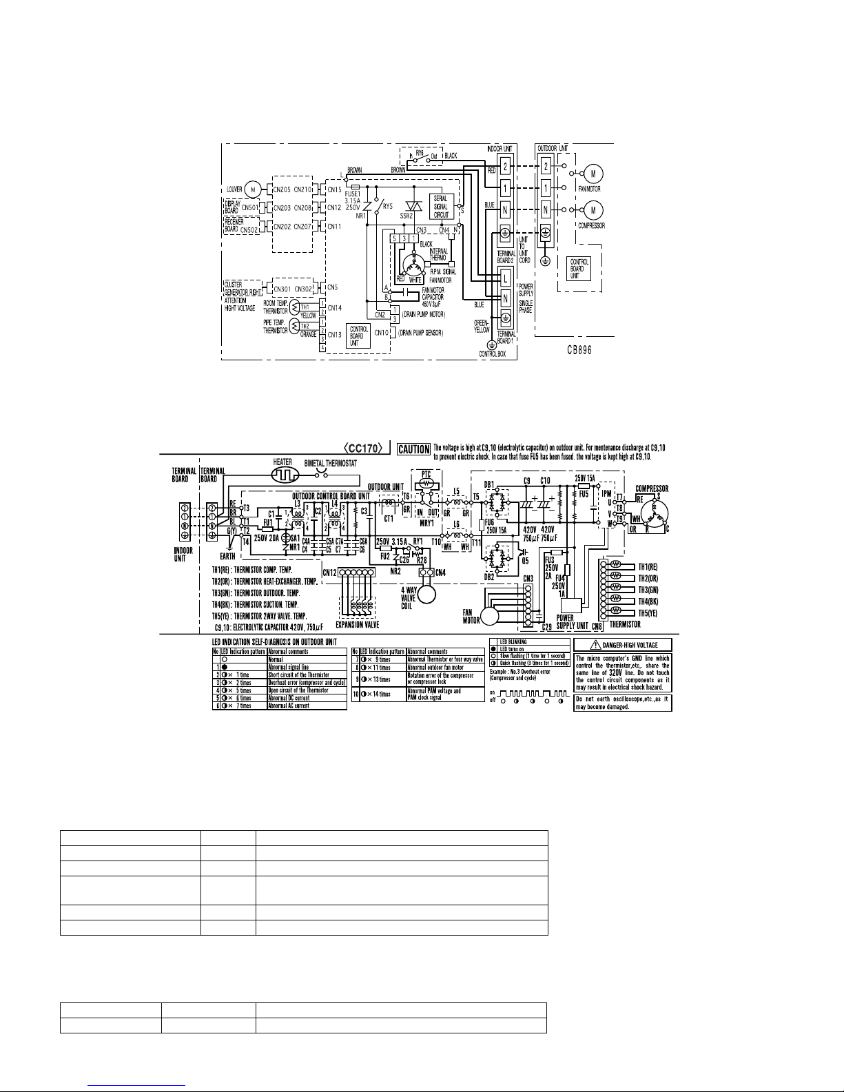
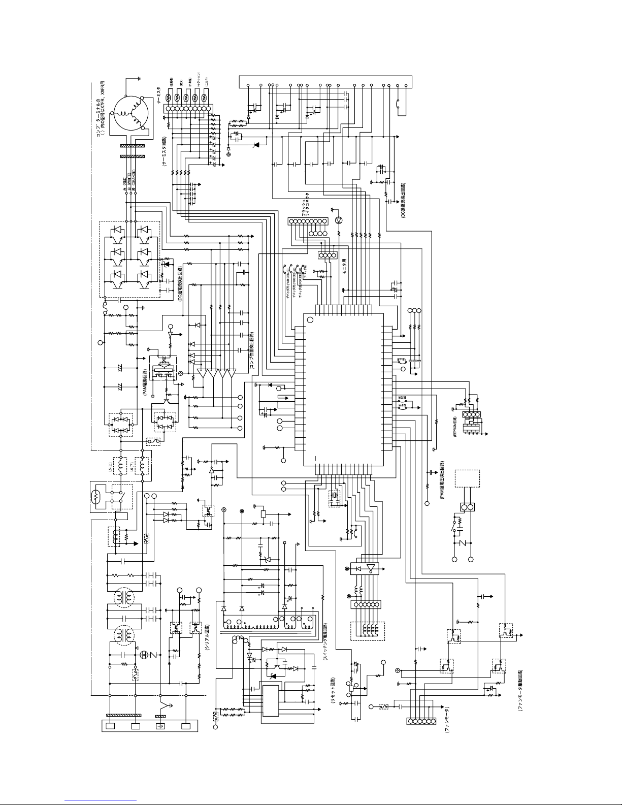
[3] WIRING DIAGRM
1. Indoor unit
1.1. GS-XP12HR-N
2. Outdoor unit
2.1. AE-X12FR-N
GSXP12HRN
[4] ELECTRICAL PARTS
1. Indoor unit
1.1. GS-XP12HR-N
DESCRIPTION MODEL REMARKS
Indoor fan motor MLB052 220 - 240V, 50Hz
Indoor fan motor capacitor – 450V, 3µF
Transformer – Primary; AC 220 - 240V, 50Hz
Secondary; AC19V, 50Hz
FUSE1 – QFS-GA062JBZZ (250V, 3.15A)
FUSE2 – QFS-GA064JBZZ (250V, 1A)
2. Outdoor Unit
2.1. AE-X12FR-N
DESCRIPTION MODEL REMARKS
Compressor 5RS92XDF D.C. brush-less motor
1 – 4
Page 6

GSXP12HRN
DESCRIPTION MODEL REMARKS
Outdoor fan motor ML-A902 DC Motor
Fu4 – QFS-GA064JBZZ
(250V, 1A)
Fu3 – QFS-GA051JBE0
(250V, 2A)
Fu2 – QFS-GA052JBZZ
(250V, 3.15A)
Fu1 – QFS-CA001JBZZ
(250V, 20A)
Fu5, 6 – QFS-CA002JBZZ
(250V, 15A)
1 – 5
Page 7
GSXP12HRN
CHAPTER 2. EXPLANATION OF CIRCUIT AND OPERATION
Service Manual
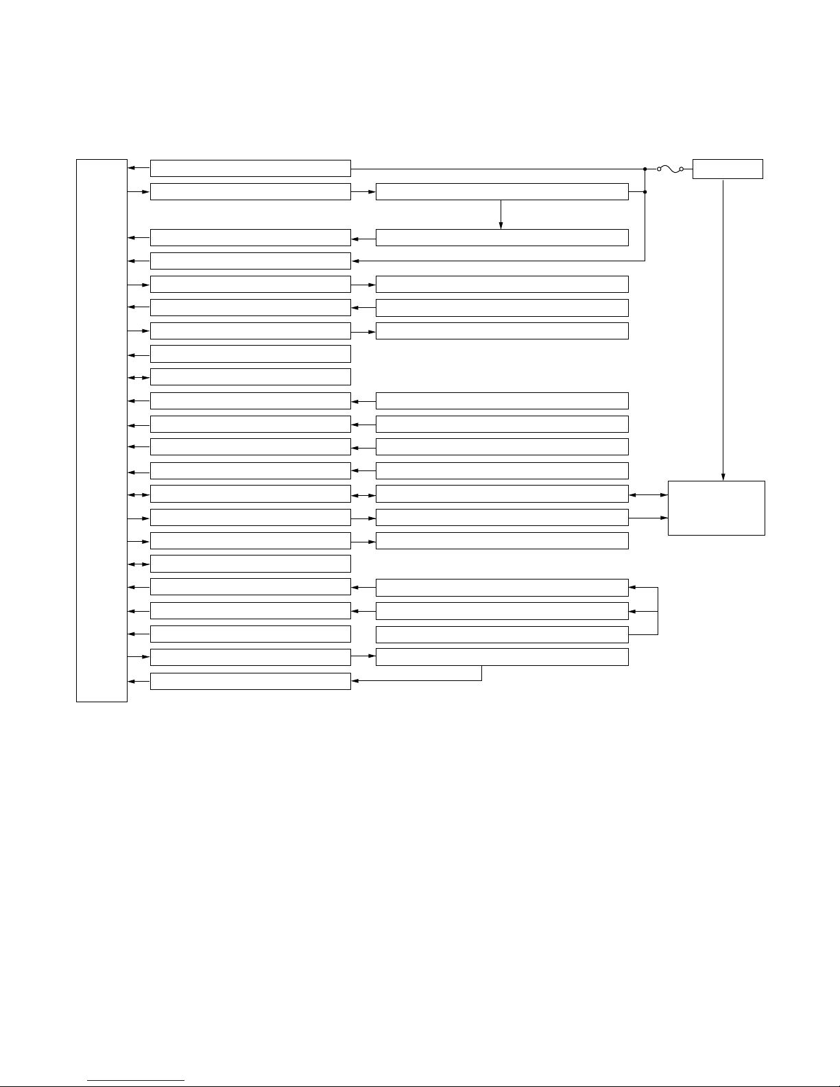
[1] BLOCK DIAGRAMS
1. INDOOR UNIT
GSXP12HRN
CPU
DC power supply circuit
Fan motor phase control circuit
Rotation pulse input circuit
AC clock circuit
Louvre motor drive circuit
Remote controller signal reception circuit
Buzzer drive circuit
CPU reset circuit
CPU oscillator circuit
Room temp. detect circuit
Heat exchanger pipe thermo circuit
Compensation circuit/ select circuit
Switchover circuit
Serial I/O circuit
Compressor relay drive circuit
LED drive circuit
Auto restart circuit
Test run circuit
Auxiliary mode
Power on circuit
Cluster generator drive circuit
Cluster generator sensor circuit
Room fan motor
Fan motor pulse detect
Flow direction control
Wireless remote control operation
Audible operation confirmation
Room temp. thermistor
Heat exchanger pipe thermistor
Model select
Wireless, preheat, auto restart
Indoor/outdoor control signal I/O
Outdoor unit power supply on/off control
LED display
Test run (forced operation)
Auxiliary mode button ON/OFF
Self diagnostics, fault diagnosis
Cluster generator
3.15 A
AC power
FUSE1
Unit-unit wiring
(AC power and
serial signals)
2 – 1
Page 8
GSXP12HRN
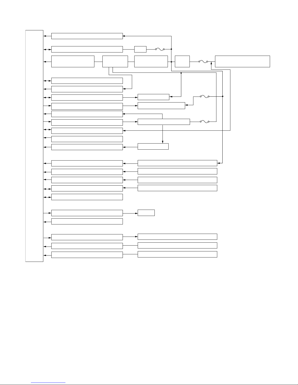
2. OUTDOOR UNIT
CPU
AC clock circuit
Pulse amplitube modulation circuit
Power supply circuit
CPU oscillator circuit
DC overvoltage detection circuit
Outdoor fan drive circuit
4-way valve relay drive circuit
DC overcurrent detection circuit
Power transistor module drive circuit
Serial I/O circuit
CPU reset circuit
Position detection circuit
AC overcurrent detection circuit
Compressor thermo circuit
Heat exchanger pipe thermo circuit
Outdoor temp. thermo. circuit
Smoothing
circuit
15A
protection
IGBT
Power factor
converter circuit
Outdoor fan
4-way valve
Power transistor module
Compressor
Current transformer
Compressor thermistor
Heat exchanger pipe thermistor
Outdoor temperature thermistor
Filter
circuit
20A
protection
3.15A
protection
15A
protection
Unit-unit wiring (AC power
and serial signals)
EEPROM
LED drive circuit
Test mode circuit
Expansion valve drive circuit Expansion valve
Suction temp. thermo. circuit Suction pipe thermistor
2-way valve temp. thermo. circuit 2-way valve thermistor
LED
2 – 2
Page 9
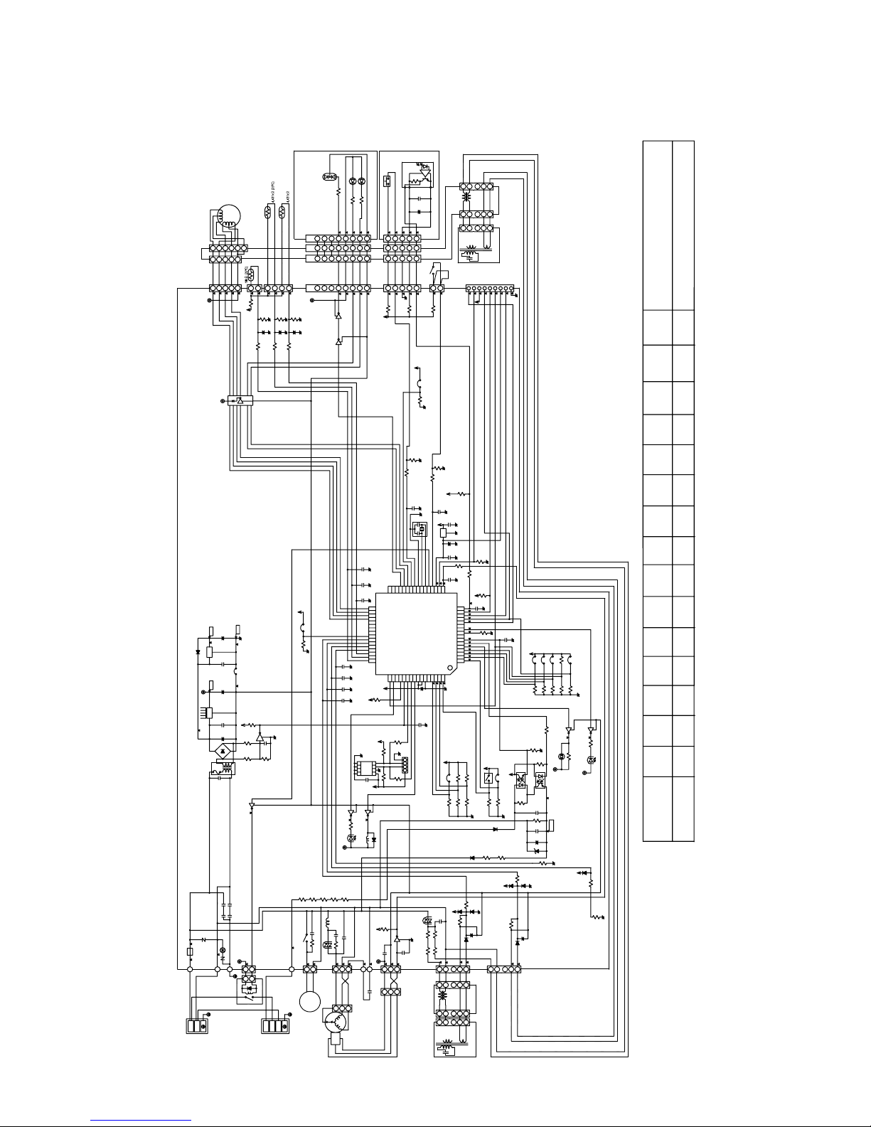
[2] MICROCOMPUTER CONTROL SYSTEM
A
T
1. INDOOR UNIT
1.1. Electronic Control Circuit Diagram
TIMER
OPERA
PLASM
CLUSTE
BL
LED501
LED502
RED
1/4W
R502
3K
3211
C56
16V
C57
16V
C58
C59
C19
1
R20
SW501
1/4W
R501
2.7K
DISPLAY BOARD UNIT
1234567
5
55
2345678
CN11
(PH)
5
1234567
47
R97
5V
50V
C50C49C48
0.1μ
50V
0.1μ0.1μ
50V
P21
P20
33P17
34
P16
35
P15
P14
36
P13
37
NC
P12
38
NC
P11
39
NC
P10
40
NC
P07
41
P06
42
P05
43
P04
44
P03
45
P02
46
P01
47
P00
48
P37
P36
495051
0.01μ
5V
50V
0.1μ0.1μ
4.7K
R63
5V
50V
5V
R22
6.8K6.8K
5
4
6
3
7
2
8
1
IC8
R21
5V
50V
0.1μ
3
1
Q3
2
470
1/2W
RY5
D18
SSR2
R19
3.3K
0.1W
5V
Q11
50V
C17
0.1μ
12V
B
A
BLUE
BLACK
3μ
213
450V
GRAY
PURPLE
FAN
MOTOR
CAPACITOR
1/4W
LED503
R503
CN
CN
16V
10K
R8
5V
203
208
CN12
JP4
2W
680
RY5
100
CN501
(PH)
12V
(PREHEAT)
R105
R9
680
275V
0.033μ
1W
R17
1
3
)
PUMP
DRAIN
(
2W
C15
CN2
88
8
(VH - WHITE)
765
R10
2W
680
SSR2
(VH)
THERMAL
PROTECTOR
2.7K
4
2
Q15
Q20
0.01μ
3
Q2
2
3
2
12V
R11
R12
2W
2W
680
680
L1
275V
0.033μ
0.01μ
C16
C71
100
275V
1W
R18
1
5
3
CN3
WHITE
BLACK
2
3
1
IC
FAN
HALL
MOTOR
(TH3)
(25ºC)
TEMP
TH2
PIPE TMEP.
1
CN
ROOM TMP.
47
R104
5V
5V
R2
22K
R1
22K
3
Q16
2
10000p
4700p
12V
1
1
D32
RY6
INOUT
VALVE
205
(PH)
TH1
(XH)
CN13
CN14
1
R4
22
(XH)
2
123
4
1/2W
R103
6.8KF
R101
R102
10KF
6.8KF
C52
16V
C53
C51
10μ
16V
10μ
10μ
+
+
+
R99
R98
10K
10K
R100
IC5
8
33K
3.3K
2
1
Q1
16V
C9
0.01μ
20K
R3
1
BCN1
S
RED
BCN2
BLACK
N
1
2
TERMINAL
BOARD2
TO
UNIT
OUTDOOR
LOUVER
MOTOR
65432
CN
210
12345
(XH)
CN15
12345
12V
12V
9
GND
C14
100μ
10V
+
OUT
7805
D17
IC3
C13
0.1μ
IN
50V
JP11
C12
12V 5V
12V
47μ
25V
+
OUT
7812
IC2
0.1μ
IN
C11
50V
C10
35V
+
1000μ
D1 ~ 4
TR1
C5
0.1μ
275V
250V
C3, 4 :C1, 2 :
C4
C3
C2
C1
250V
NR2
SA1
250V
FUSE1
3.15A
NR1
N
L
G
BROWN
YELLOW
GREEN /
BLUE
BROWN
N
L
TERMINAL
BOARD1
POWER
SUPPLY
SINGLE
PHASE
GSXP12HRN
IC501
AUX. (TEST RUN)
+
4
2133
4
1
2
4
213
4
1
2
3
R96
47
1/2W
5V
JP99
R93
10K
10K
R92
50V
C47
0.1μ
8M
NCNCNC
303132
Vss
P27
P26
P25
P24
P23
P22
**
IC1
M3803
P35
P34
P33
P32
P31
P30
Vcc
52
NC
+
C21
C8
1K
R24
(XA)
CN80
1234
R23
1K
2
2W
1
3
50V
C18
2W
0.1μ
CN4
(XH)
312
(SM)
BLUE
13876
50V
C502
0.1μ
C501
47μ
10V
CN
RECEIVER BOARD UNIT
502
CN
202
CN
207
)
DRAIN
FLOAT
SWITCH
DUMMY
(
3
1
CN10
R95
(XA -
47
POWER ON
R94
33K
R89
10K
R106
10K
5V
50V
C45
0.1μ
OSC1
50V
C44
5V
1
IC7
3
+
50V
C43
1μ
50V
C42
R88
10K
C41
50V
17181920212223242526272829
P42
P41
P40
Xin
Xout
RESET
CNVss (Vpp)
Vref
AVss
P67
P66
P65
P64
P6364
6362616059585756555453
NC
1μ
50V
16V
0.01μ
FILTER
5V
JP7
33K
C22
275V
.01μ
SSR1
2W
6.8K
R126
R26
6.8K
2W
R125
6.8K
6.8K
R25
NF301
1
3
ATTACH -
GREEN)
0.1μ
0.1μ
0.1μ
P43
P44
P45
P46
P47
P50
P51
P52
P53
P54
P55
P56
P57
P60
P61
P62
R45
5V
CN206
NF201
CN201
876
1
3
76531
(CLUSTER1)
NONE
CN201, CN6, D10, D11, D12,
CN206, C24, R125, R126
)
MENT
(
R124
MODEL
10K
RESET
MO
OE
SERIAL5CLOCK
12V1BUSY
GND
(PH)
(CN99)
9
7
6
4
35V2
8
5V
NONE
NONENONE
NF201,
CLUSTER1,
TH3
R107
R47
R44
13K NONE
R46
JP
10K
NONE
R43
JP99
R86
4.7K
R85
680
R83
3.3K
5V
50V
C40
16
15
1000p
14
13
12
11
10
9
R80
NC
8
4.7K
7
6
5
4
3
2
1
R47
R44
D7
16V
C32
0.01μ
MULTI / SINGLE
/FLOOR
REMOTE
CEILING
CON.
SELECT
5V
10K
47μ
C23
25V
(XA)
CLUSTER2
4
SW1
5V
JP5
1
R41
R42
R37
33K
33K
D15
C26
R32
R33
2W
2W
11K
11K
R31
D11
5V
R30
10K
D10
876
3
1
R46
R43
D13
R29
D8
R28
+
D6
CN5
98741
98741
CN302
CN301
876
76531
(SPARE)
TIME
REDUCE
WIRELESS
HOT KEEP
AUTO RES.
5V
JP1
JP2
JP6
JP3
R84
33K
33K
33K
33K
33K
R62
R107
R61
R59
R60
R40
3
2.7K
R39
1.8K
R38
22K
3
14
2
PC1
PC817X3
2
3
4.7K
250V
C27
0.01μ
R36
100K
50V
0.047μ
+
ZD1
10K
D12
47μ
+
C24
25V
(XA)
CN6
3
1
1
Q10
Q9
2
2
R57
470
1W
BZ1
3
R58
1.8K
SSR1
2
12V
12V
PC2
PC853H
-24V
C25
35V
100μ
1M
R128
5V
D16
R56
10K
R55
100K
JP11
USEUSE
JP7
JP6
NONE
JP5
USE USE
JP4
USE
JP3
JP2
USE
JP1
USE
NO.
GS-XP12HR
2 – 3
Page 10
GSXP12HRN
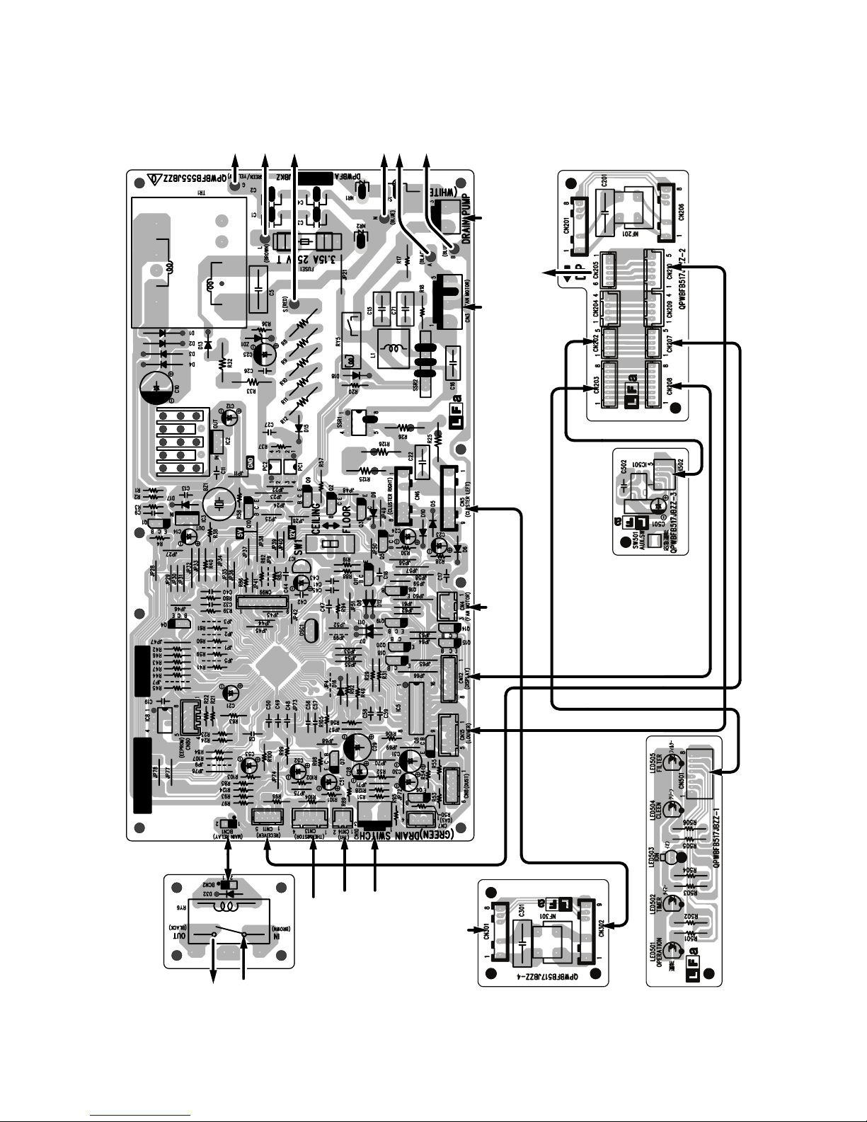
1.2. Printed Wiring Board
to
CONTROL BOXto"L" OF TB1to"2" OF TB2
to
FAN M CAPACITOR
to
"N" OF TB1
}
from
DRAIN PUMP
(WHITE CONNECTOR)
(OPTION)
to
LOUVER M
from
FAN MOTOR
from
FAN MOTOR
}
from
PIPE THERMISTOR
from
ROOM THERMISTOR
from
DRAIN PUMP(OPTION)
to
"1" OF TB2
from
"L" OF TB1
(GREEN CONNECTOR)orSHORTEN CIRCUIT ATACHMENT
from
(LEFT)
CLUSTER UNIT
2 – 4
Page 11
2. OUTDOOR UNIT
2.1. Electronic Control Circuit Diagram
GSXP12HRN
PS21563 or 21564
IPM
15A
FU5
250V
j
PTC
1μF
275V
275V
1μF
275V
FC1
TERMINAL
BOARD
WP
VP
UP
VPI
EARTH
YELLOW
GREEN/
C
(R)
S
(THERMISTOR)
5V
(C)
R100
R
FC3 FC4
(THERMISTOR CIRCUIT)
T9
T7
T8
V33
U32
W34
N
35
R50
26
CIN
R7
R128
MRY1
2.7kF
R88
2
T1
13KF
R127
R6
23.7KF
510K
4
2
4
0V
1/4W
T13
BROWN
1
13KF
23.7KF
T11
T10
25
CF0
Q7
5V
R107
2
0V
8
150
R110
V-P
Q5
18
FU6
15A
250V
WH
WH
e
d
D12
D13
FU2
3.15A
250V
4700pF
250V
C6A
C6
C7A
C7
4700pF
250V
4700pF
250V
C5A
C5
C4
C4A
4700pF
250V
PC1
SA1
NR1
C13
20A
FU1
250V
T4
YELLOW
GREEN/
31
P
M
C14
630V
0.33μ
R126
1/2W
R125
1/2W
270KD
270KD
R5
R2
1/2W
300KF
255KF
1/2W
C10
750μ
+
C9
420V 420V
750μ
+
DB1
T5
GR
GR
OUT
IN
GR
T6
CT1
R89
C3
1/4W
510K
R43
3
L4
1
C2
3
L3
1
1μF
C1
R1
1M
T12
1/2W
T2
BLUE
N
1
330K
10Kx5 R63~67
5W
R49
0.02
1.8KF
C59
C58
c
KRC105S
330
3
6
R101, 102
1/2W 47K x 2
5V
4
1
PC817XP3
0.1μ
D1
FC2
R51 ~ 53
PC4
R111
ZD3
1000P
0.022μ
TLP351
5
2.2K
R91
R103, 104
R74
TH4
TH5
TH3
TH2
65432
798
10
CN8
R68 ~ 72
6.8KF x 5
D11
0V
C70~74
16V 10μ x 5
0V
0.01μ x 5 C65 ~ 69
1/2W
470KF x 3
R99 100
15K
R112
R57 100
R59 100
R58 100
0V
D24
D23
D22
D21
5
11
4
15V
3
2
14
13
R114
1M
1.8K
0V -P
R115
5V
1.8K
R60
1.8K
R61
1.8K
DB2
R62
μ
7
9
.01
C
0
R147
10K
C79
10V
6.8KF
R90
1.0KF
D2
R104
R103
R102
R101
1W 47K x 2
a
C75
4.7K
3
PC2
PC853HXP
2
R4
3.3K
250V
C12
4700P
T3
RED
2
220μ
1000P
1
4
P
K
0
0
5V
.3
C83
0
3
R106
1
6
Q
2S
C10
2
0V
R
C8
K
K
5
2
0
2
1
R
5V5V
3
4
PC3
2
1
PC81716NIP
μ
1
C81
.0
0
R146
100K
b
0V
R75
2.7K
R76
56K
D6
2
TR1
3
(SERIAL I/O CIRCUIT)
1K
2W
1K
R41 R42
1K
2W 2W
FB
R11
1/2W 1M
V
0
5
2
FU4
A
1
j
R8R9R10
1/2W 1M
VUFS
VUFB
IPM
3
4
1
C49
0.1μ
33 x 2
33 x 2
D8
C50
R47A, 48A
25V
R47, 48
1/4W
1/4W
100μ
C37
25V
ZD4
330μ
C38
0.1μ
15V
0V
R56
20.5KF
R55
20.5KF
R54
20.5KF
25V
C60
0.1μ
C86
0.1μ
R113
19.1KF
C61
330P
50V
DETECT CIRCUIT)
(ROTOR POSITION
50V
C62
330P
C63
50V
330P
C64
25V
0.1μ
678910
12
1
IC8
KIA339
5V
N
W
C93
0.1μ
V
C30
10V
U
5V
0V
μ
1
0
.
0
5V
15V
13V
5
0
C4
I
8
7
7
W
8
1
6
R2
4
K
2
2
2
R
5
2
μ
R
3
KF
C21
.03
.65
0
1
3
K
IC3
2
8
R
6
1
2
.5K
R
1
K
0
R22
1
μ
0
V
0
2
5
8
C
2
6
9
V
μ
5
0
C1
3
5
1
7
D
8
7
3
1
0
W
1
D3
2
R17
D5
μ
V
0
0
C15
1
5
K
8
5
1
.
1
R
PF
0
KV
2
C27
1
2
4
rain
D
R12
1/2W 1M
1/2W 1M
1~
R13
1/2W 1M
cc
V
8
C2
2
I
7
4
STR -L
1/2W 1M
6
D20
100μ
C23
K
0
R82
1
R19
G
6
8
5
SA1
2
VVFB
9
D9
C39
1000P
M
0V
a
b
R92
10K
μ
1
.
0
R26
KF
.64
4
9
K
2
1
Q
ZD1
ce
r
6
ou
S
B
9
/F
P
OC
10
ND
7
G
VVFS
7
C51
0.1μ
C52
25V
100μ
C40
1234567
CONNECTOR)
(FRASH WRITER
JP7
JP8
0V
S
T
Q
0V
18V - P
5
8
.1μ
C
0
K
0
R87
1
μ
V
0
5
5
C84
3
1
4
1
D
5
6
D4
P
0
0
3
3
C16
K
3
.
R20
3
4
1
R
10
1000P
JP9
P
0V -
D15
VPI
11
0
8
6
12
CND
1
2
34
5
6
7
89
10111213141516171819
VWFB
VWFS
15
13
C53
0.1μ
D10
25V
C54
100μ
C41
1000P
9
8
S
T
R
1
JP10
R154
10K
5V
(FOR DEBUG)
10K
R155
P42
P43
P44
P45
P46
P50
P51
P52
P53
P54
P55
P56
P57
AVCC
AVR
AVSS
P60
P61
P62
P63
MD0
RST
MD1
10K
10K
R94
R93
0V
5V
10
P
0
8
C18
6
6
.6
1
R1
.6
R15
1
P
0
7
C17
4
0V
VPI
18
16
C42
1000P
5V
LED1
Q
R73
2
3
4
P40
P41
MD2X1X0
OSC1 4MHz
K
.7
R29
4
(SWITCHING POWER
SUPPLY CIRCUIT)
(RESET CIRCUIT)
VNI
28
2.2K
(LED CIRCUIT)
(CN)
MONITOR
5V
P37
VSS
P00
0V
10K
R34
5V
13V
13V
EXPANSION
R79
IC5
PST993D
5V
R78
VCCCP36
IC1
P01
9
VALV COIL
100
3
1
270
UN
21
C55
0.1μ
C56
0.1μ
C57
0.1μ
C43
1000P
R134 100
R135 100
P34
P35
(W)
(Z)
(B)
(O)
P02
P03
10K
R35
RY1
6
+
0.1μ
C32
2
C31
0.1μ
C
R136 100
JP16
MRY1
F0
VNO
VN
WN
22
23
N
VNC
20
24
27
35
JP17
0V
C47
10V
100μ
C44
1000P
C48
0.1μ
10K
R45
5V
C45
0.1μ
1K
R46
0V
1000P
C46
(DC OVERCURRENT CHECK CIRCUIT)
R133 100
R132 100
R137 100
0.1μ
C95
C94
100μ
10V
0.1μ
C98
V
W
51504948474645444342414039383736353433
KID65004AP
U
R38 1K
R37 1K
R36 1K
0V
JPF
C36
C35
C34
1000P x 3
c
0V
1K
0V
10K
R129
4.7K
R30
5V
(PAM OVER CURRENT CIRCUIT)
RY1
e
CNE
IC6
10K
R31
R32
431
VALV
4-WAY
3
R28
1/2W
275V
C26
3
120
0.033μ
COIL
1
d
R144
2.2K
R33
2
8
756
0V
124
(EEPROM CIRCUIT)
CN4
NR2
(4 - WAY VALVECIRCUIT)
C76
1000P
0V
6.8K
JP2
0V
JP1
5V
C88
1000P
1K
R116
N
52535455565758596061626364
(U)
P32
P33
P30
(Y)
(X)
(V)
VSS
P27
(W)
(V)
P26
P25
(U)
P24
P23
P22
P21
P20
P17
P16
P15
P14
P13
P12
P11
P10
P07
(Y)
(W)
P04
P05
P06 P31
32313029282726252423222120
8
IC7
0V
3
4
2
1
5
CN12
5V
Q9
R81
KRC105S
Q4
KRA106S
(FAN MOTOR)
10K
KRC105S
0V
Q10
KRA106S
R84
9.53KF
10V
47μ
C78
0V
R86
6.8KJ
(FAN MOTOR CIRCUIT)
Q3
0V
C77
15V
0.01μ
6.8K
R85
5V
R83
10K
0V
C29
400V
0.1μ
1
7
3
2
4
CN3
5
R
C33
50V
1μ
270
R77
0V
j
2A
FU3
250V
2 – 5
Page 12

GSXP12HRN
2.2. Printed Wiring Board
2 – 6
Page 13

[3] FUNCTION
Heating
(24ºC)
Heating
(23ºC)
Cooling
(24ºC)
Cooling
(24ºC)
(Room temperature
-2ºC)
Cooling
(25ºC)
Cooling
(26ºC)
(Dry)
Room
temperature
(ºC)
When the cooling operation only can use winter kit
21
29
01018 28 34
Outdoor
temperature (ºC)
Cooling
(25ºC)
Cooling
(26ºC)
Heating
(22ºC)
1. INDOOR UNIT
GSXP12HRN
1.1. Startup control
The main relay remains off during the first 45 seconds (first safety
time) immediately after the power cord is plugged into an AC outlet in
order to disable outdoor unit operation and protect outdoor unit electric
components.
1.2. Restart control
Once the compressor stops operating, it will not restart for 180 seconds to protect the compressor.
Therefore, if the operating compressor is shut down from the remote
control and then turned back on immediately after, the compressor will
restart after a preset delay time.
(The indoor unit will restart operation immediately after the ON switch
is operated on the remote control.)
Compressor operation
Compressor ON Compressor can
Compressor remains OFF
for 180 seconds
OFF operation on
remote control
ON operation on
remote control
1.3. Temperature Adjustment
1.3.1 Cooling
When the room temperature is higher than the preset temperature by
2°C or more, the unit runs at the maximum operation frequency until
the temperature comes down to the preset temperature.
When reaching the preset temperature, the unit runs at the frequency
calculated by the fuzzy operation and switches to the normal control.
1.3.2 Heating
When the room temperature is lower than the preset temperature by
3.5°C or more, the unit runs at the maximum operation frequency until
the temperature comes down to the preset temperature.
When reaching the preset temperature, the unit runs at the frequency
calculated by the fuzzy operation and switches to the normal control.
1.3.3 Dry
After operation begins, 2 minutes of the room temperature is stored in
memory, and that becomes the set value.
1.4. Indoor fan control
1.4.1 Cooling
The fan speed can be selected from “Auto”, “Soft”, “Low”,and
“HIgh”.When “Soft”, “Low” or “HIgh” is selected, the fanspeed is constant regardless of the room temperature.When “Auto” is selected, the
fan speed automatically changes between “Soft” and “HIgh” depending on the difference between the room and preset temperature.
Control for indoor freezing prevention
If the temperature of the indoor heat exchanger stays below approximately 0°C for 4 minutes during cooling or dry, this control stops the
compressor. Over 2°C the compressor will run again.
1.4.2 Heating
Control for cold air blowing prevention
When heating begins, this control stops the indoor fan until the temperature of the indoor heat exchanger reaches 23°C. It also stops the
fan if the temperature goes below 21°C during operation.
turn ON
Compressor ON
Temperature of the indoor heat exchanger
35ºC
The indoor fan operates at low speed.
23ºC
Preset Fan speed
The indoor fan stops.
1.5. Automatic operation
The operating mode and temperature setting are determined by the
room temperature and the external air temperature.
The operating mode will changeover automatically with the following condition.
1) From cooling to heating
Cooling mode will changeover to heating mode when condition of
indoor temperature 1.7°C lower than the set temperature conditions for 5 minutes.
2) From heating to cooling
Heating mode will change over to cooling mode when condition of
indoor temperature 1.3°C higher than the set temperature conditions for 25 minutes under compressor off condition.
3) When the set temperature is adjusted within the range of ±2°C by
the remote control’s key.
( ), the changeover judgement room temp. will also be shifted
within the range of ±2°C.
1.6. ON-timer
The ON-timer is set by pressing the ON-timer button.
In order to attain the set temperature at the set time.
1.7. OFF-timer
The OFF-timer is set by pressing the OFF-timer button. Operation is
as follows:
Set temperature
Cooling
Heating
By fuzzy computing
Set the shift up time
Final Cooling setting + 1°C
Heating setting - 3°C
Dry Same as above
(Final setting + 1°C)
* During Heating
Timer set time
3ºC
1
hour
Timer operation starts Stops
Room
temperature
2 – 7
32ºC
21ºC
Page 14

GSXP12HRN
* During Cooling / Dry
Timer set time
Room
1
hour
Timer operation starts
1ºC
1.8. Swing louvre
The louvre is moved by a stepping motor to perform swing and fixing in
the set position.
If the “FLOW DIRECTION” button is prossed during swing, it will stop.
If the “FLOW DIRECTION” button is pressed while it is stopped, it will
swing.
The vertical adjustment louvre will change its angle continuously.
Press the SWING button again when the vertical adjustment louvre is
at the desired position.
• The louvre will stop moving within the range shown in the diagram.
• The adjusted position will be memorized and will be automatically
set to the same position when operated the next time.
COOL and DRY modes
Floor standing
Ceiling suspended
Adjustment range
HEAT mode
temperature
Stops
Floor standing
Ceiling suspended
• Power ON/OFF
• Automatic operation mode setting
• Swing louver
• Plasmacluster operation mode
Setting not memorized
• Timer setting
• Full power setting
1.13. Error diagnostic display
Indoor unit
1) If the operation is stopped and the emergency operation button is
pressed down for 5 seconds or more, the self-diagnosis memory
can be recalled.
2) Details of self-diagnosis (error mode) are informed by the flashing
number as well as the lighting pattern of the operation lamp which
flashes with the timer lamp.(For details, refer to Error diagnostic
method.)
1.14. Compressor relay
1) It is ON during operation, and when operation is stopped, goes
OFF after a delay of 120 seconds (not immediately).
Air conditioner
operation
Compressor
relay
ON
OFF
ON
OFF
120 sec.
The adjustment range is
narrower the SWING range
in order to prevent
condensation from dripping.
The range is wide so the air
flow can be directed
toward the floor.
1.9. One-hour operation
If this button is pressed when operation is stopped, operation will
begin and then stop after 1 hour.
If pressed when it is operating, will stop after one hour.
1.10. Full power operation
Immediately begins cooling or heating at maximum power and air flow.
(During heating)
Operates at setting of 32 °C.
(During cooling)
Operates at setting of 18 °C.
1.11. Power ON start
If a jumper wire is inserted into the place indicated JP99 on the indoor
control board, and the power plug is inserted. cooling or heating will be
automatically determined by the room temperature sensor on the main
unit, and operation will begin.
1.12. Auto Restart
When power failure occures, after power is recovered, the unit will
automatically restart in the same setting which were active before the
power failure.
Operating mode (Cool, Heat, Dry)
• Temperature adjustment (within 2°C range) automatic operation
• Temperature setting
• Fan setting
• Air flow direction
2) The minimum OFF time of the relay is 60 seconds. It will not go ON
again before 60 seconds elapses.
Air conditioner
operation
Compressor
relay
ON
OFF
ON
120 sec.
ON
ON
OFF
60 sec.
3) If air conditioner operation is turned on again during the 120 second delay before the compressor relay goes off, the compressor
relay will stay on.
Air conditioner
operation
Compressor
relay
ON
ON
ON
OFF
120 sec.
1.15. Drain water control (option)
When the float switch turns OFF (full level), the drain pump is forcibly
operated for 5 minutes.
After the pump operates for 5 minutes, the pump turns OFF if the float
switch is ON (empty). If the float switch is not ON (empty) even when 6
minutes elapse from the time of pump ON, the equipment stops operating due to a drain pump error.
1.16. Plasmacluster Ion function
Operating the Plasmacluster Ion button while the air conditioner is in
operation or in non-operation allows the switching of the operation
mode in the following sequence: “Air Clean operation” → “Stop”.
• “Self Clean operation” generates about equal amounts of (+)ions
and (-)ions from the cluster unit to provide clean air.
2 – 8
Page 15

If the Plasmacluster Ion generation function is operated together with
the air conditioner operation, the indoor unit fan speed and louver
direction are in accordance with the air conditioner settings.
2. OUTDOOR UNIT
GSXP12HRN
If the Plasmacluster Ion generation function is used without operating
the air conditioning function, the indoor unit fan operates at a very low
speed and the upper louver is angled upward and the lower louver
remains horizontal. (The airflow volume and direction can be changed
by using the remote control.)
2.1. Outdoor unit 2-way valve freeze prevention control
If the temperature of the outdoor unit 2-way valve remains below 0°C
for 10 consecutive minutes during cooling or dehumidifying operation,
the compressor operation stops temporarily in order to prevent freezing.
When the temperature of the 2-way valve rises to 10°C or higher after
about 180 seconds, the compressor restarts and resumes normal
operation.
2.2. Indoor unit overheat prevention control
During heating operation, if the temperature of the indoor unit heat
exchanger exceeds the indoor unit heat exchanger overheat prevention temperature (about 45 to 54°C) which is determined by the operating frequency and operating status, the operating frequency is
decreased by about 4 to 15 Hz. Then, this operation is repeated every
60 seconds until the temperature of the indoor unit heat exchanger
drops below the overheat protection temperature.
Once the temperature of the indoor unit heat exchanger drops below
the overheat protection temperature, the operating frequency is
increased by about 4 to 10 Hz every 60 seconds until the normal operation condition resumes.
If the temperature of the indoor unit heat exchanger exceeds the overheat protection temperature for 60 seconds at minimum operating frequency, the compressor stops operating and then restarts after about
180 seconds, and the abovementioned control is repeated.
2.3. Outdoor unit overheat prevention control
During cooling operation, if the temperature of the outdoor unit heat
exchanger exceeds the outdoor unit heat exchanger overheat prevention temperature (about 55°C), the operating frequency is decreased
by about 4 to 15 Hz. Then, this operation is repeated every 60 seconds until the temperature of the outdoor unit heat exchanger drops to
about 54°C or lower.
Once the temperature of the outdoor unit heat exchanger drops to
about 54°C or lower, the operating frequency is increased by about 4
to 10 Hz every 60 seconds until the normal operation condition
resumes.
If the temperature of the outdoor unit heat exchanger exceeds the outdoor unit heat exchanger overheat protection temperature for (120 sec
: outdoor temperature ≥ 40°C • 60 sec : outdoor temperature < 40°C)
at minimum operating frequency, the compressor stops operating and
then restarts after about 180 seconds, and the abovementioned control is repeated.
2.4. Compressor overheat prevention control
If the temperature of the compressor exceeds the compressor overheat prevention temperature (110°C), the operation frequency is
decreased by about 4 to 10 Hz. Then, this operation is repeated every
60 seconds until the temperature of the compressor drops below the
overheat protection temperature (100°C).
Once the temperature of the compressor drops below the overheat
protection temperature, the operating frequency is increased by about
4 to 10 Hz every 60 seconds until the normal operation condition
resumes.
If the temperature of the compressor exceeds the overheat protection
temperature (for 120 seconds in cooling operation or 60 seconds in
heating operation) at minimum operating frequency, the compressor
stops operating and then restarts after about 180 seconds, and the
abovementioned control is repeated.
2.5. Peak control
If the current flowing in the air conditioner exceeds the peak control
current (see the table below), the operation frequency is decreased
until the current value drops below the peak control current regardless
of the frequency control demand issued from the indoor unit based on
the room temperature.
Model Peak control current
Cooling operation Heating operation
GS-XP12HR-N Approx. 6.4 A Approx. 7.5 A
2.6. Outdoor unit fan delay control
The compressor stops immediately after cooling, dehumidifying or
heating operation is shut down, but the outdoor unit fan continues
operation for 50 seconds before it stops.
2.7. Defrosting
2.7.1 Reverse defrosting
The defrost operation starts when the compressor operating time
exceeds 20 minutes during heating operation, as shown below, and
the outside air temperature and the outdoor unit heat exchanger temperature meet certain conditions. When the defrost operation starts,
the indoor unit fan stops. The defrost operation stops when the outdoor unit heat exchanger temperature rises to about 13C or higher or
the defrosting time exceeds 10 minutes.
20 min or more 20 min or more 20 min or more
Start of
heating
operation
Defrosting
Max. 10 min
Defrosting
Max. 10 min
2.8. Winter cool
Cooling operation is available during the winter season by the built in
winter cool function.
Lower limit of outdoor temperature range is -10°C DB.
When the outside air temperature is low, the outdoor unit fan operates
at slower speed.
NOTE: Built-in protect device may work when outdoor temperature
falls below 21°C DB., depending on conditions.
2 – 9
Page 16

GSXP12HRN
3. Explanation of cluster circuit
The cluster unit generates cluster ions, which are circulated throughout the room by the air flow created by the blower fan (indoor unit fan motor) in
the air conditioner unit.
1) When microcomputer output turns "H," the IC6 output changes to "Lo," turning ON the SSR and applying 230 V to the cluster unit for the generation of cluster ions (positive and negative ions).
12V
R76
C23
RE RH
Cluster unit
1
1
3
3
5
6
AC230V
Microcomputer output
IC6
R75
R23
SSR
R20
4. Outline of PAM circuit
4.1. PAM (Pulse Amplitude Modulation)
The PAM circuit varies the compressor drive voltage and controls the rotation speed of the compressor.
The IGBT shown in the block diagram charges the energy (electromotive force) generated by the reactor to the electrolytic capacitor for the inverter
by turning ON and OFF.
Reactor L5
DB1
AC
230V
Noise
filter
Reactor L6
+
IPM
Compressor
AC clock
detection
circuit
DB2
IGBT
[PAM drive circuit]
Microcomputer (IC1)
PAM drive circuit block diagram
IGBT
drive
circuit
Overvoltage
detection
circuit
Compressor
position
detector
2 – 10
Page 17

GSXP12HRN
When the IGBT is ON, an electric current flows to the IGBT via the reactor (L5), (L6) and diode bridge (DB2).
When the IGBT turns OFF, the energy stored while the IGBT was ON is charged to the voltage doubler capacitor via the diode bridge (DB1).
As such, by varying the ON/OFF duty of the IGBT, the output voltage is varied.
DB1
Stored energy
IGBT ON
IGBT OFF
Reactor
L6
L5
DB2
IGBT
4.2. High power factor control circuit
This circuit brings the operating current waveform closer to the waveform of commercial power supply voltage to maintain a high power factor.
Because of the capacitor input, when the PAM circuit is OFF, the phase of the current waveform deviates from the voltage waveform as shown below.
To prevent this deviation, a current is supplied during the periods indicated by "O" in the diagram.
To determine the length of period to supply a current, the zero-cross timing of the AC input voltage is input to the microcomputer via the clock circuit.
The power source frequency is also determined at the same time.
The IGBT turns ON after the time length determined by the zero-cross point to supply a current to the IGBT via the reactor.
This brings the current waveform closer to the voltage waveform in phase.
As described above, the ON/OFF operation of the IGBT controls the increase/decrease of the compressor power supply voltage (DC voltage) to
improve the compressor efficiency and maintain a high power factor by keeping the current phase closer to that of the supply voltage.
AC voltage waveform
AC voltage waveform
AC current waveform
AC voltage and current waveforms when PAM is OFF
AC current waveform
Zero-cross detection
IGBT ON period
AC voltage and current waveform when PAM is ON
4.2.1 Detailed explanation of PAM drive circuit sequence
AC voltage waveform
Clock
IGBT ON
A
BC
50Hz
A
1.2mS
B
1.2mS
C
0.25 2.3mS
4.2.2 AC clock (zero-cross) judgment
• The clock circuit determines the time from one rising point of the clock waveform to the next rising point.
The detected clock waveform is used to judge the power source frequency (50Hz).
• The zero-cross of the AC voltage is judged as the rising of the clock waveform, as shown in the diagram above.
4.2.3 IGBT ON start time (delay time B)
• Based on the zero-cross of the AC voltage, the IGBT turns ON after a delay time set according to the power source frequency.
4.2.4 IGBT ON time (C)
• After the above delay time, the IGBT turns ON to supply a current to the reactor.
• The ON time of the IGBT determines the amount of energy (level of DC voltage rise) supplied to the reactor.
DC voltage level in each operation mode (varies depending on external load conditions)
– Cooling operation --- 220 to 240 V
– Heating operation --- 220 to 280 V
2 – 11
Page 18

GSXP12HRN
R2
255K
C10C9
420V
750uF
R5
300K
R7
23.7KR823.7K
0V
0V
0V
IC8
15V
R113
19.1KF
R112
15K
5V
R114
1M
R115
1.8K
R116
1K
5
4
2
(Overvoltage detection)
During abnormal voltage output
IC1
38
4.3. PAM protection circuit
To prevent excessive voltage of PAM output from
damaging the IPM and electrolytic capacitor as well
as the control printed circuit board (PCB), this circuit
monitors the PAM output voltage and turns off the
PAM control signal and PAM drive immediately
when an abnormal voltage output is generated. At
the same time, it shuts off the compressor operation.
The PAM output voltage is distributed to pin (4) of
the comparator (IC8). If this voltage exceeds the reference voltage at pin (5) of the IC8, the output of the
comparator (IC8) reverses (from H to L) and it is
input to pin (38) of the microcomputer (IC1) to halt
the PAM drive.
The protection voltage level is as follows.
4.3.1 Details of troubleshooting procedure for PAM
1) PAM shutdown due to error
1) When the DC voltage detection circuit sends a signal exceeding the specified voltage to the microcomputer
DC voltage of 350 V or higher (detection circuit input voltage of about 9.2 V or higher) [IC8 pin (4)]
– When an error is detected
• PAM IGBT turns OFF.
• Compressor turns OFF.
• All units shut down completely when the error occurs four times.
2) When the outdoor unit clock waveform differs from the specified value immediately before the PAM IGBT turns ON
When there is no clock waveform input
When a clock signal of other than specified power source frequency (50/60 Hz) is input
– When an error is detected
• PAM IGBT does not turn ON.
• Compressor operates normally.
• Complete shutdown does not occur.
2) PAM error indication
In case of error “1)”
– An error signal is sent to the indoor unit as soon as an error is generated.
• Malfunction No. 14-0 is indicated when the error code is called out by the indoor unit's self-diagnosis function.
– The LED on the outdoor unit flashes 14 times when an error is generated.
• The LED continues flashing in the 14-time cycle even after the compressor stops operating.
• The LED turns off (data is deleted from the memory) when the outdoor unit power is turned off.
In case of error “2)”
– An error signal is sent to the indoor unit as soon as an error is judged.
• Malfunction No. 14-1 is indicated when the error code is called out by the indoor unit's self-diagnosis function.
– The LED on the outdoor unit flashes 14 times when an error is judged.
• The LED on the outdoor unit flashes in normal pattern when the compressor stops operating.
(Compressor OFF or Thermostat OFF from remote control)
* When a user complains that the air conditioner does not provide sufficient cool air or warm air
In addition to conventional error-generating reasons, there is a possibility that the PAM IGBT does not turn ON even if the compressor is operating.
In that case, the DC voltage does not rise even though the compressor is operating, and lowers to the 180-VDC level.
– Check items
• Clock circuit check
• PAM IGBT check
• Fuse (Fu6) open-circuit check
5. Explanation of IPM drive circuit
The IPM for compressor drive is made by Mitsubishi Electric.
The power supply for the IPM drive, the shunt resistance for overcurrent detection, etc., are provided outside the IPM (control PCB).
2 – 12
Page 19

GSXP12HRN
D
5.1. IPM drive power supply circuit
The power supply for the upper-phase IGBT (HU, HV, HW) drive employs a bootstrap system, and provides power to the upper-phase IC.
The 15-V power supply for the lower-phase IC is provided by the control printed circuit board (PCB).
5.1.1 Brief explanation of bootstrap system (single power drive system)
To supply power to the upper-phase IC, the microcomputer (IC1) turns ON the lower-phase IGBT (LU, LV, LW).
This results in a charging current that flows to the electrolytic capacitor of each upper-phase IC input and charges the bootstrap capacitor with a 15-V
current.
The power supply for the subsequent stages is charged while the lower-phase IGBT is ON in ordinary compressor drive control.
Initial charge period
VDB
Charging current group
Bootstrap capacitor
(HU,HV,HW)
HVIC
High-voltage-withstanding,
high-speed recovery diode
P(Vcc)
U,V,W,
V
D
VCIN(n)
(LU,LV,LW)
Bootstrapcircuit
LVIC
N-side
IGBT
N(GN
2 – 13
Page 20

GSXP12HRN
5.1.2 DC overcurrent detection circuit
When a current of about 25 A or higher flows through the shunt resistance (R49) on the control printed circuit board (PCB), the voltage at this resistance is input to IPM CIN pin (26). Then, the gate voltage of the lower-phase IGBT (LU, LV, LW) inside the IPM turns OFF to cut off the overcurrent. At
the same time, an L output of about 1.8 ms is generated from IPM Fo pin (24), and this results in an L input to overcurrent detection input pin (34) of
the microcomputer (IC1) and turns OFF the PWM signal output (IC1 pins (51) through (56)) to the IGBT gate.
Protection circuit status
(Lower phase)
Internal IGBT gate
Output current Ic (A)
Sense voltage relative
to shunt resistance
Error output Fo
SET
RESET
(About 22 A)
SC
a1
SC reference voltage
Delay by CR time constant circuit
About 1.8 ms
P
IPM overcurrent
detection circuit
Shunt resistance
R49
N
CiN
26
FO
24
Overcurrent
5V
IC1
34
0V
6. 120° energizing control (digital position detection control)
This control system detects the digital position detection signal and adjusts the rate of acceleration/deceleration accordingly.
The motor's induced voltage waveform is input to the comparator in the form of PWM-switched pulse waveform, and a position detection signal is
generated as a reference voltage equaling 1/2 of 280 VDC. However, since there is no induced voltage waveform when the PWM waveform is OFF,
the microcomputer performs internal processing so that detection is enabled only when it is ON. Based on the detected position signal, actual PWM
waveform output timing is determined. Since it does not use a filter circuit, the detection accuracy is high.
2 – 14
Page 21

GSXP12HRN
The microcomputer performs internal processing to cancel spike voltage during the regenerative process.
Furthermore, even if the induced voltage is low, position detection is still possible, thus allowing sensor-less operation at low rotation speed in the initial stage of operation. This reduces the starting current and improves the IPM reliability.
Terminal voltage waveform
Reference voltage
(1/2 of DC voltage)
Spike voltage
(cancelled)
Comparator output waveform
(Position signal waveform)
2 – 15
Page 22

GSXP12HRN
GSXP12HRN
CHAPTER 3. TROUBLESHOOTING
Service Manual
[1] TROUBLESHOOTING GUIDE
1. SELF-DIAGNOSIS FUNCTION AND DISPLAY MODE
1) To call out the content of the self-diagnosis memory, hold down the emergency operation button for more than five seconds when the indoor unit is
not operating.
a) According to the content of the self-diagnosis memory, the Operation LED (main category) and the Plasmacluster Ion LEDs (sub-category)
flash in sync with the Timer LED on the indoor unit.
b) In the event a complete shutdown occurs due to a malfunction, the Operation LED (red), Timer LED (yellow) and Plasmacluster Ion LED (blue)
flash to indicate the general information of the generated malfunction.
c) If the power cord is unplugged from the AC outlet or the circuit breaker is turned off, the self-diagnosis memory loses the stored data.
2) Display of detailed self-diagnosis result with main category and sub-category indications
When malfunction information is called out, the main category and sub-category of the self-diagnosis result are indicated by the Operation, Timer,
and Plasmacluster Ion LEDs on the indoor unit.
* 1:Example of self-diagnosis result displayed on indoor unit: Suction thermistor open-circuit error
*1: Example of self-diagnosis result displayed on indoor unit: Suction thermistor open-circuit error
Timer LED [yellow]
Operation LED [red]
Plasmacluster Ion LED [blue]
ON
OFF
ON
OFF
Basic flashing cycle due to error
Figures in ( ) indicate numbers (binary notation) assigned based on the flashing sequence.
Flashing for main category indication
Flashing for sub-category indication
1 sec 1 sec 1 sec 5 sec
Main category Sub-category
Malfunction No.
* 2:The self-diagnosis display function of the outdoor unit indicates the error information by flashing LED1 on the outdoor unit according to the
content of self-diagnosis.
The self-diagnosis display function of the outdoor unit is active only for about 3 to 10 minutes after self-diagnosis is performed during operation,
and the display returns to normal condition after this display period.
The content of self-diagnosis cannot be called out by the self-diagnosis display function of the outdoor unit.
Example of self-diagnosis display on outdoor unit : Compressor high-temperature abnormality
ON
OFF
1 sec 1 sec 0.6 sec 1 sec 1 sec 1 sec 1 sec 1 sec 1 sec 1 sec0.6 sec 0.6 sec 0.6 sec
* 3:The content of diagnosis is transferred to the indoor unit via serial communication, but it does not trigger a complete shutdown operation.
: Flashes in 2-sec intervals (normal), : On, : Off, : Flashes 3 times in 0.2-sec intervals
Status of
indoor/outdoor
units
Indoor/outdoor
units in
operation
Indoor/outdoor
units in
complete
shutdown
Indoor/outdoor
units in
complete
shutdown
Indoor unit in
operation
Outdoor unit in
temporary stop
Indoor unit in
operation
Outdoor unit in
temporary stop
Indication by
LED1 on
outdoor unit
*2
Normal
flashing
1 time
2 times
3 times
Indication by operation lamp on indoor unit
Lighting pattern at the time of timer lamp lighting
(When LED1 on the outdoor unit flashes in 2-sec intervals, the outdoor unit is in normal condition.)
Content of diagnosis
Main
category
Outdoor unit
thermistor
short-circuit
Cycle
temperature
Dry
operation
Sub-category
Normal
Heat exchanger
thermistor short-circuit
error
Outside temperature
thermistor short-circuit
error
Suction thermistor
short-circuit error
2-way valve thermistor
short-circuit error
Compressor hightemperature error
Temporary stop due to
compressor discharge
overheat *3
Temporary stop due to
outdoor unit heat
exchanger overheat *3
Temporary stop due to
outdoor unit heat
exchanger overheat *3
temporary stop due to
2-way valve freeze *3
Temporary stop due to
dehumidifying
operation *3
Inspection location/method Remedy
(1) Measure resistance of the outdoor unit
thermistors.
(TH2 to TH5: Approx. 4.4 k at 25¼C)
(2) Check the lead wire of the outdoor unit
thermistor for torn sheath and shortcircuit.
(3) No abnormality found in above
inspections (1) and (2).
(1) Check the outdoor unit air outlet for
blockage.
(2) Check if the power supply voltage is
198V or higher at full power.
(3) Check the pipe connections for
refrigerant leaks.
(4) Measure resistance of the outdoor unit
compressor thermistor.
(TH1: Approx. 53 k at 25¼C)
(5) Check the expansion valve for proper
operation.
(Temporary stop for cycle protection)
(Temporary stop for cycle protection)
(Temporary stop for cycle protection)
(Temporary stop for cycle protection)
(Temporary stop for cycle protection)
Off for 5 seconds
Operation lamp
Cluster lamp
Operation lamp
Cluster lamp
Operation lamp
Cluster lamp
Operation lamp
Cluster lamp
Operation lamp
Cluster lamp
Operation lamp
Cluster lamp
Operation lamp
Cluster lamp
Operation lamp
Cluster lamp
Operation lamp
Cluster lamp
Operation lamp
Cluster lamp
(BLUE)
(BLUE)
(BLUE)
(BLUE)
(BLUE)
(BLUE)
(BLUE)
(BLUE)
(BLUE)
(BLUE)
(RED)
(RED)
(RED)
(RED)
(RED)
(RED)
(RED)
(RED)
(RED)
(RED)
Malfunction No.
Main
category
category
00
1-0
2-0
3-0
Sub-
-1
-2
-3
-1
-2
-3
-4
(1) Replace the outdoor unit
thermistor assembly.
(2) Replace the outdoor unit
thermistor assembly.
(3) Replace the outdoor unit control
PCB assembly.
(1) Ensure unobstructed air flow from
the outdoor unit air outlet.
(2) Connect power supply of proper
voltage.
(3) Charge the specified amount of
refrigerant.
(4) Replace the outdoor unit
compressor thermistor assembly.
(5) Replace the expansion valve coil,
expansion valve or outdoor unit
control PCB assembly.
3 – 1
Page 23

GSXP12HRN
: Flashes in 2-sec intervals (normal), : On, : Off, : Flashes 3 times in 0.2-sec intervals
Status of
indoor/outdoor
units
Indoor/outdoor
units in
complete
shutdown
Indoor/outdoor
units in
complete
shutdown
Indoor/outdoor
units in
complete
shutdown
Indoor/outdoor
units in
complete
shutdown
Indoor unit in
operation
Outdoor unit in
temporary stop
Indoor/outdoor
units in
complete
shutdown
Indoor/outdoor
units in
complete
shutdown
Indoor/outdoor
units in
complete
shutdown
Indoor unit in
operation
Outdoor unit in
complete
shutdown
Indication by
LED1 on
outdoor unit
*2
5 times
6 times
7 times
9 times
11 times
13 times
14 times
Indication by operation lamp on indoor unit
Lighting pattern at the time of timer lamp lighting
(When LED1 on the outdoor unit flashes in 2-sec intervals, the outdoor unit is in normal condition.)
Malfunction No.
(BLUE)
(BLUE)
(BLUE)
(BLUE)
(BLUE)
(BLUE)
(BLUE)
(BLUE)
(BLUE)
(BLUE)
(BLUE)
(BLUE)
(BLUE)
(BLUE)
(BLUE)
(BLUE)
(BLUE)
(BLUE)
(BLUE)
(BLUE)
(BLUE)
(BLUE)
(RED)
(RED)
(RED)
(RED)
(RED)
(RED)
(RED)
(RED)
(RED)
(RED)
(RED)
(RED)
(RED)
(RED)
(RED)
(RED)
(RED)
(RED)
(RED)
(RED)
(RED)
(RED)
Main
category
category
5-0
6-0
7-0
9-0
11 -0
13 -0
14 -0
17 -0
18 -0
Off for 5 seconds
Operation lamp
Cluster lamp
Operation lamp
Cluster lamp
Operation lamp
Cluster lamp
Operation lamp
Cluster lamp
Operation lamp
Cluster lamp
Operation lamp
Cluster lamp
Operation lamp
Cluster lamp
Operation lamp
Cluster lamp
Operation lamp
Cluster lamp
Operation lamp
Cluster lamp
Operation lamp
Cluster lamp
Operation lamp
Cluster lamp
Operation lamp
Cluster lamp
Operation lamp
Cluster lamp
Operation lamp
Cluster lamp
Operation lamp
Cluster lamp
Operation lamp
Cluster lamp
Operation lamp
Cluster lamp
Operation lamp
Cluster lamp
Operation lamp
Cluster lamp
Operation lamp
Cluster lamp
Operation lamp
Cluster lamp
Sub-
-1
-2
-3
-4
-1
-1
-2
-3
-3
-1
-1
-1
Content of diagnosis
Main
category
Outdoor unit
thermistor
open-circuit
Outdoor unit
DC
Outdoor unit
AC
Outdoor unit
cooling/heati
ng switchover
Outdoor unit
DC fan
DC
compressor
Outdoor unit
active filter
Wires
between
units
Wires
between
units
Sub-category
Heat exchanger
thermistor open-circuit
error
Outside temperature
thermistor open-circuit
error
Suction thermistor
open-circuit error
2-way valve thermistor
open-circuit error
Discharge thermistor
open-circuit error
DC overcurrent error
IPM pin level error
AC overcurrent error
AC overcurrent error in
OFF status
AC maximum current
error
AC current deficiency
error
Thermistor installation
error or 4-way valve
error
Torque control error
Outdoor unit DC fan
rotation error
Compressor startup
error
Compressor rotation
error
PAM overvoltage error
PAM clock error
Serial open-circuit
Outdoor unit does not
turn on due to
erroneous wiring
Serial short-circuit
Serial erroneous wiring
Inspection location/method Remedy
(1) Check connector CN8 of the outdoor unit
thermistor for secure installation.
(2) Measure resistance of outdoor
thermistors TH1 to TH5.
(3) Check the lead wires of thermistors TH1
through TH5 on the outdoor unit control
PCB for open-circuit.
(4) No abnormality found in above
inspections (1) through (3).
(1) IPM continuity check
(2) Check the IPM and heat sink for secure
installation.
(3) Check the outdoor unit fan motor for
proper rotation.
(4) No abnormality found in above
inspections (1) through (3).
(5) No abnormality found in above
inspections (1) through (4).
Check the IPM is attached correctly to the
outdoor unit control PWB
(1) Check the outdoor unit air outlet for
blockage.
(2) Check the outdoor unit fan for proper
rotation.
(1) IPM continuity check (1) Replace the outdoor unit control
(1) Check the outdoor unit air outlet for
blockage.
(2) Check the outdoor unit fan for proper
rotation.
(1) Check if there is an open-circuit in the
secondary winding of the current
transformer of the outdoor unit control
PCB.
(2) Check if the refrigerant volume is
abnormally low.
(3) Check if the refrigerant flows properly.
(1) Check to make sure outdoor unit
thermistor TH2 (heat exchanger) TH5 (2way valve) are installed in correct
positions.
(2) Measure resistance of thermistors TH1
and TH5.
(3) Check the 4-way valve for proper
operation.
(4) No abnormality found in above
inspections (1) through (3).
(1) Check if the refrigerant volume is
abnormally low.
(2) Check the 4-way valve for proper
operation.
(3) Check to see if the compressor type is
correct.
(1) Check connector CN3 of the outdoor unit
DC fan motor for secure installation.
(2) Check the outdoor unit fan motor for
proper rotation.
(3) Check fuse FU3.
(4) Outdoor unit control PCB
(1) Check the colors (red, white, orange) of
the compressor cords for proper
connection. (PCB side, compressor side)
(2) Check if the IPM terminal resistance
values are uniform.
(3) No abnormality found in above
inspections (1) and (2).
(4) No abnormality found in above
inspections (1) through (3).
(1) Check the AC power supply voltage for
fluctuation.
(2) No abnormality found in above inspection
(1).
(1) Check the PAM clock for proper input. (1) Replace the outdoor unit control
(1) Check the wires between units.
(2) Check voltage between Nos. 1 and 2 on
the indoor/outdoor unit terminal boards.
(1) Check the wires between units.
(2) Check the outdoor unit fuse.
(3) Check 15-V, 13-V and 5-V voltages on
the PCB.
Check resistance between IPM terminals.
(4)CheckpinsNo.5and8ofconnector
CN3A of the outdoor unit fan motor for
short-circuit.
(5) Outdoor unit control PCB
(1) Correct the installation.
(2) Replace the outdoor unit
thermistor assembly.
(3) Replace the outdoor unit
thermistor assembly.
(4) Replace the outdoor unit control
PCB assembly.
(1) Replace the outdoor unit control
PCB assembly.
(2) Correct the installation (tighten the
screws).
Apply silicon grease.
(3) Replace the outdoor unit fan
motor.
(4) Replace the outdoor unit control
PCB assembly.
(5) Replace the compressor.
Replace the outdoor unit control PWB
assembly
(1) Ensure unobstructed air flow from
the outdoor unit air outlet.
(2) Check the outdoor unit fan motor.
PCB assembly.
(1) Ensure unobstructed air flow from
the outdoor unit air outlet.
(2) Check the outdoor unit fan motor.
(1) Replace the outdoor unit control
PCB assembly.
(2) Charge the specified amount of
refrigerant.
(3) Correct refrigerant clogs.
(2-way valve, 3-way valve, pipe,
expansion valve)
(1) Correct the installation.
(2) Replace the thermistor assembly.
(3) Replace the 4-way valve.
(4) Replace the outdoor unit control
PCB assembly.
(1) Charge the specified amount of
refrigerant.
(2) Replace the 4-way valve.
(3) Replace the compressor with the
correct part.
(1) Correct the installation.
(2) Replace the outdoor unit fan
motor.
(3) Replace the outdoor unit control
PCB assembly.
(4) Replace the outdoor unit control
PCB assembly.
(1) Correct the installation.
(U: Red, V: White, W: Orange)
(2) Replace the outdoor unit control
PCB assembly.
(3) Replace the outdoor unit control
PCB assembly.
(4) Replace the compressor.
(1) Connect stable power supply.
(2) Replace the outdoor unit control
PCB assembly.
PCB assembly.
(1) Connect stable power supply.
(2) Replace the outdoor unit control
PCB assembly.
(1) Correct the wiring.
(2) Replace the fuse/outdoor unit
control PCB assembly.
(3) Replace the outdoor unit control
PCB assembly.
(4) Replace the outdoor unit fan
motor.
(5) Replace the outdoor unit control
PCB board.
(1) Check the wires between units. (1) Correct the wiring.
(1) Check the wires between units. (1) Correct the wiring.
3 – 2
Page 24

GSXP12HRN
: Flashes in 2-sec intervals (normal), : On, : Off, : Flashes 3 times in 0.2-sec intervals
Status of
indoor/outdoor
units
Indoor/outdoor
units in
complete
shutdown
Indoor/outdoor
units in
operation
Indoor/outdoor
units in
operation
Indoor/outdoor
units in
operation
Indication by
LED1 on
outdoor unit
*2
Indication by operation lamp on indoor unit
Lighting pattern at the time of timer lamp lighting
(When LED1 on the outdoor unit flashes in 2-sec intervals, the outdoor unit is in normal condition.)
Content of diagnosis
Main
category
Indoor unit
fan
Indoor unit
control PCB
Cluster circuit
Drain pump
unit
Sub-category
Indoor unit fan error
EEPROM data error
Cluster voltage error
Drainpumpunit
error
Off for 5 seconds
Operation lamp
Cluster lamp
Operation lamp
Cluster lamp
Operation lamp
Cluster lamp
Operation lamp
Cluster lamp
Operation lamp
Cluster lamp
Operation lamp
Cluster lamp
(BLUE)
(BLUE)
(BLUE)
(BLUE)
(BLUE)
(BLUE)
category
(RED)
(RED)
(RED)
(RED)
(RED)
(RED)
Malfunction No.
Main
Sub-
category
19 -0
20 -0
22 -0
30 -0
-1
-2
Malfunction indications due to erroneous wiring during air conditioner installation
Inter-unit wiring
error mode
Indoor
unit
1
2
3
Indoor
unit
1
2
3
Indoor
unit
1
2
3
Outdoor
unit
1
2
3
Outdoor
unit
1
2
3
Outdoor
unit
1
2
3
Symptom
Indoor unit relay Turns On momentarily,
then turns Off.
Malfunction diagnosis display "18-1"
Indoor unit relay Relays turns Off after
about 30 sec.
Malfunction diagnosis display None
(Displays "18-0" when malfunction code
is called out.)
Indoor unit relay Relays turns Off after
about 30 sec.
Malfunction diagnosis display None
(Displays "18-0" when malfunction code
is called out.)
Inter-unit wiring
error mode
Indoor
unit
Outdoor
unit
1
2
3
Indoor
unit
Outdoor
unit
1
2
3
Inspection location/method Remedy
(1) Check the indoor fan motor for proper
rotating operation.
(Check fan lock.)
(2) Check the lead wire of the indoor fan
motor for open-circuit.
(3) Check CN1 of the indoor unit fan motor
for secure installation.
(4) No abnormality found in above
inspections (1) through (3).
(EEPROM read data error) (1) Replace the indoor unit control
(1) Check if the cluster feedback voltage is
proper (0.1 V to 4.9 V).
(2) Check CN5 of the cluster for secure
installation.
(1) Check connector CN2 and CN10.
(1) Replace the indoor fan motor.
(2) Replace the indoor fan motor.
(3) Correct the installation of CN1 of
the indoor fan motor.
(4) Replace the indoor unit control
PCB.
PCB.
(1) Replace the cluster unit.
(2) Correctly install CN5 of the
cluster.
(1) Replace the
(2) Re-insertion of CN2 and CN10.
Drain pump unit
Symptom
Indoor unit relay Turns On momentarily,
1
then turns Off.
Malfunction diagnosis display "18-1"
2
3
Indoor unit relay Turns On momentarily,
1
then turns Off.
Malfunction diagnosis display "18-1"
2
3
unit.
3) In addition to those described above, the following error, which does not result in a complete shutdown, is notified by the flashing LED on the
indoor unit.
Malfunction
Serial open-circuit error
Flashing LED ( : flashing in 1-sec intervals)
Operation Timer Cluster (blue) Cluster (green)
(The Operation and Cluster LED conditions vary based on the equipment operation.)
Malfunction No. (main category)
17 Serial open-circuit error
3 – 3
Page 25

GSXP12HRN
2. CAUTION IN CHECKING PRINTED CIRCUIT BOARDS (PWB) [GS-XP12HR-N]
2.1. Non-insulated control circuit
The GND terminals of the low-voltage circuits (control circuits for microcomputer and thermistors and drive circuits for expansion valve and relays) on
the control printed circuit board (PWB) are connected to the compressor drive power supply (320-VDC negative terminal). Therefore, exercise utmost
caution to prevent electric shock.
If a measuring instrument used for the test is grounded, its chassis (ground) has the same electric potential as the 0-V probe. Since non-insulated circuits have the following voltage potential difference from the ground, connection of the grounding wire results in a short-circuit between the 0-V line
and the ground, thus allowing an excessive current to flow to the tester to cause damage.
If the sheaths of the thermistor lead wires or expansion valve lead wires inside the outdoor unit become damaged due to pinching by the front panel
or other metal parts or contacting a pipe, a high voltage can flow and destroy the circuits. To prevent these problems, carefully conduct assembly
work.
Outdoor unit circuits
AC230V
320-VDC line
Terminal board
2
1
3
Reactor
Ground
Point (E)
+
-
0-V line Point (F)
Voltage at point (E)
IPM
M
Compressor
motor
Reason
The oscilloscope (chassis ground) has the same electric
potential as the 0-V probe. The entire electronic control section
of the outdoor unit has a voltage potential difference from the
ground as shown in the above diagram. When the oscilloscope
is set up, the 0-V line and the ground voltage (ground) will be
short-circuited, resulting in an excessive current flow to cause
damage to the oscilloscope or indoor electric circuits.
Do not touch the
cabinet or bring metal
parts into contact with
the cabinet.
Danger!!
Do not connect
the grounding
wire.
320V
0-V line
0-V line voltage (point (F))
3. DIODE BRIDGE CHECK METHOD
Turn off the power and let the inverter electrolytic capacitor (C9, C10) discharge completely. Then use a tester and check continuity.
When using a digital tester, the (+) and (-) tester lead wires in the table must be reversed.
Needle-type tester
45 B
Value in ( ) is for digital tester.
Normal resistance value
(several M )
3 – 4
Page 26

[2] THERMISTOR TEMPERATURE CHARACTERISTICS
Connect with IC clip
Test mode cooling at 40 Hz
0.1. Temperature properties of indoor thermistors
GSXP12HRN
K
TH1 Room temperature thermistor
80
60
Resistance
40
Room temperature
thermistor TH1 (yellow)
25ºC resistance 10 K
Connector
CN14
20
0
-10 0 10203040
0.2. Temperature properties of outdoor thermistors
Connector
CN8
110
500K
5.8K
Temperature( )
Tester
4.17K
Resistance
(K )
400K
300K
200K
100K
0
Resistance at 25
52.76 k
-20 0 20 60 80 100 120
TH1 Compressor thermistor
12
Tester
+
-
3.06K
2.28K
1.72K
Resistance
(K )
TH2 Heat exchange thermistor
TH3 Valve temperature thermistor
40K
0ºC resistance
30K
20K
14.5 K
25ºC resistance
4.431 K
Resistance ( )
10K
0
-20 0 20 60
Temperature (ºC)
Connector
CN8
110
40K
Resistance at 0
30K
14.57 k
Resistance at 25
20K
10K
0
4.431 k
-20 0 20 6040
Temperature( )
TH2 TH5
(In case of TH2 heat exchanger thermistor)
+
Tester
40
-
TH2 Heat exchanger thermistor
TH3 Outdoor air temperature thermistor
TH4 Suction thermistor
TH5 2-way valve thermistor
Connector
CN13
TH2
14
Tester
Compressor thermistor
Thermistor
Heat exchanger thermistor
Outdoor air temperature thermistor
Suction thermistor
2-way valve thermistor
No.
TH1
No. (1) - No. (2)
TH2
No. (3) - No. (4)
TH3
No. (5) - No. (6)
TH4
No. (7) - No. (8)
TH5
No. (9) - No. (10)
Connector
Color
Before measuring resistance,
Red
disconnect connectors from PWB.
Orange
Green
Black
Yellow
[3] HOW TO OPERATE THE OUTDOOR UNIT INDEPENDENTLY
1. Cooling in 40 Hz fixed mode
To operate the outdoor unit independently, short-circuit the sections indicated by arrows in the diagram below with an adapter, and apply 230 VAC
between (1) and (N) on the terminal board of the outdoor unit. This allows the outdoor unit to be operated in cooling mode independently.
(Do not operate the outdoor unit in this condition for an extended period of time.)
Short-circuit negative terminal of
Connect with IC clip
Test mode cooling at 40 Hz
C9C10
(L2)
capacitor (C33) and jumper wire
(JP16) using IC clip, etc.
3 – 5
Page 27

GSXP12HRN
GSXP12HRN
CHAPTER 4. REFRIGERATION CYCLE
[1] FLOW FOR REFRIGERANT
Indoor unit
Evaporator
Flare coupling Flare coupling
Service Manual
3
[2] STANDARD CONDITION
Indoor side Outdoor side
Dry-bulb
Tem p.
Cooling 27°C47%35°C 40%
Heating 20°C– 7°C 87%
* REFRIGERANT PIPE LENGTH 5.0m
Relative
Humidity
Dry-bulb
Tem p.
Relative
Humidity
3-way
valve
Silencer
Accumulator
4
Comp-
ressor
Reverse valve
Outdoor unit
1
Coil
Condenser
C
2-way
valve
Heating Cooling
Strainer
s
Expansion
valve
2
[3] TEMPERATURE AT EACH PART AND PRESSURE IN 3-WAY VALVE
Model GS-XP12HR-N
Operation mode MAX. TEST RUN
Cool Heat Cool Heat
No. R.P.M. 5000 5600 2500 2500
1 73.6°C 70.4°C68°C55°C
241°C2°C38°C3°C
314°C34°C16°C27°C
415°C1°C17°C4°C
3-way valve pres-
sure (MPaG)
0.81 2.72 1.03 1.93
[4] PERFORMANCE CURVES
NOTE
1) Indoor fan speed: Hi
2) Vertical adjustment louver "0°”, Horizontal adjustment louver "front"
3) Indoor air temp. : Cooling 27°C, Heating 20°C
4) Power source : 230V, 50Hz
4 – 1
Page 28

0.1. At Cooling 0.2. At Heating
-5 0 5 7 10
3.0
3.5
4.0
4.5
35
37
39
1000
1100
800
900
Heating capacity(kW)
Outside air temp.(ºC)
Input(W)
Outlet air temp.(ºC)
1000
900
800
Input(W)
700
16
14
3.9
3.7
3.5
3.3
3.1
Cooling capacity(kW)
25 30 35 40
Outside air temp.(ºC)
12
Outlet air temp.(ºC)
GSXP12HRN
4 – 2
Page 29

GSXP12HRN
Side Cover
Side Cover
Front Panel
GSXP12HRN
CHAPTER 5. DISASSEMBLING PROCEDURE
Service Manual
[1] DISASSEMBLY OF INDOOR UNIT
CAUTION: DISCONNECT THE UNIT FROM POWER SUPPLY BEFORE ANY SERVICING.
1) Slide 2 Grille hooks to the left, and open the Grille. (Right and left
Grille.)
3) Remove the screw fixing the Side cover. (Right and left Side cover.)
GRILLE HOOK
2) Remove 4 screws fixing the Girlls.
Slide
4) Remove 2 screws fixing the Grille. (Right and left Grille.)
5 – 1
Page 30

GSXP12HRN
5) Remove 1 screw fixing the Angle.
Remove the Angle to the direction of arrows.
6) Cut the fixing band.
Disconnect 2 connectors (CN202, CN203).
Remove the screw fixing the Display unit.
5 – 2
Page 31

GSXP12HRN
7) Slide the Display unit to the direction of arrow.
Slide
8) Remove 2 screws fixing the Angle to the Front panel.
10)Support the Front panel with your hand, and remove the screw.
11)Remove the Front panel to the position where the Front panel is
separated from the Drain pan.
9) Remove 8 screws fixing the Front panel.
DRAIN PAN
This position
5 – 3
Page 32

12)Remove the Front panel to the direction of arrow.
CAUTION: DO NOT DAMAGE THE DRAIN PAN WITH THE DIS-
PLAY HOLDER.
DISPLAY HOLDER
GSXP12HRN
CAUTION: WHEN YOU ASSEMBLE THE FRONT PANEL TO
DRAIN PAN, INSERT HOOK OF THE FRONT PANEL
BETWEEN ANGLE AND DRAIN PAN (2 POSITIONS).
(ACTUALLY ASSEMBLE THE FRONT PANEL TO
THE DRAIN PAN AFTER FIXING THE DISPLAY
HOLDER TO THE FRONT PANEL.)
HOOK OF
FRONT
PANEL
DRAIN PAN
Insert
ANGLE
CAUTION: DISCHARGE THE WATER IN THE DRAIN PAN
ASS'Y BEFORE REMOVING THE DRAIN PAN
ASS'Y.
13)Loosen the screw of the Hose band. Remove the Drain hose.
Slide
Angles hold the Front panel and
the Drain pan in these positions.
5 – 4
Page 33

GSXP12HRN
14)Remove 9 screws fixing the Drain pan ass'y.
16)Tilt the Drain pan ass'y, slide the Drain pan ass'y to the direction of
arrow.
Right and left side.
Right and left side.
15)Remove 3 insulators and 4 screws fixing the Drain pan ass'y.
Insulator
17)Disconnect 4 connectors (CN206, CN207, CN208 and CN210).
Remove 2 screws fixing the Top duct cover R.
5 – 5
Page 34

18)Disconnect the connector (CN302).
Remove 2 screws fixing the Top duct cover L.
19)Remove 2 screws fixing the top duct.
GSXP12HRN
21)Remove 2 screws fixing the Top duct cover R. Remove the Top
duct cover R and H-louver ass'y.
20)Tilt the Top duct for removing the rib of the Top duct , remove the
unit to the direction of arrow.
H-louver ass'y
TopductcoverR
22)Remove 6 screws fixing the End plate sub.
5 – 6
 Loading...