


Greenline HT Plus
C and E
User Guide
Art. no: 290410-9 Version: 1.0
FOR THE USER
INDEX

3
Manual for Heat pump Greenline HT Plus C and E
IVT Industrier AB, 2004-06-27
Article number: 290410-9
Version 1.0
Copyright © 2004. IVT Industrier AB. All rights reserved.
This manual contains copyright protected information that is the property of IVT Industrier AB. No part of this document may be copied or forwarded, electronically or mechanically,
without prior, written permission from IVT Industrier AB. This includes photographing and translation to another language.
Thank you for choosing a heat pump from
IVT Industrier
We hope that our heat pump meets your expectations and gives you many years of energy saving. We want you and
your family to enjoy a good economy at the same time as you actively safeguard the environment. We have taken today’s
demands on heat pumps into consideration and believe that your Greenline HT Plus will give you many useful functions in
the future. Your heat pump features an advanced control unit that monitors and controls the temperature in the house and
contributes towards improved overall economy. The heat pump Greenline HT Plus has, for example, a holiday function,
that's to say the heat pump can be set at a “low level” while you are away on holiday.
IVT is the leading heat pump manufacturer in the Nordic Countries. More than every second heat pump comes from IVT.
We have worked with solutions to reduce energy consumption on the environment’s terms for more than 30 years. Today
we can present the widest range of heat pumps for effi cient energy saving in all types of housing and properties.
Johnny Wärnelöv
Managing director IVT Industrier AB

4
Contents
FOR THE USER .................................................................................................... 5
Important information ....................................................................................... 5
This is how your heat pump works ..................................................................... 6
Technology in and around the heat pump ................................................................................................................6
Component parts of the heat pump .................................................................... 8
Control unit Rego 637 ..................................................................................... 10
The control unit’s two methods to control the heat pump ........................................................................................11
The control panel ............................................................................................ 12
Buttons and lamps ................................................................................................................................................12
Menu dial .............................................................................................................................................................13
How to use the control panel .................................................................................................................................13
Basic functions (Customer level 1) ................................................................... 13
Menu outline for Basic functions (Customer level 1) .............................................................................................14
Select scrolling information on the menu display ...................................................................................................14
Set the heating ......................................................................................................................................................15
Set the desired room temperature .......................................................................................................................... 18
Set the heat pump for extra hot water .................................................................................................................... 18
Heating and hot water settings ..............................................................................................................................19
Read the temperatures on the heat pump ...............................................................................................................19
Extra functions (Customer level 2) ................................................................... 21
Menu outline for Extra functions (Customer level 2) .............................................................................................21
Temperature settings ............................................................................................................................................22
Set extra heat curve with mixing valve ..................................................................................................................23
Hot water settings .................................................................................................................................................24
Timer control ........................................................................................................................................................24
Reading operating times on the heat pump and additional heat ............................................................................25
Set the time and date ............................................................................................................................................26
Alarms given by the heat pump .............................................................................................................................27
Return to factory settings .......................................................................................................................................27
Maintenance ................................................................................................... 28
Opening the front cover .........................................................................................................................................28
Sight glass .............................................................................................................................................................28
Expansion vessel ...................................................................................................................................................29
Particle fi lter ......................................................................................................................................................... 29
Checking the protective anode ...............................................................................................................................30
Savings .......................................................................................................... 31
What to do if a fault occurs .............................................................................. 32
Dimmed menu display ..........................................................................................................................................32
Fuses and reset buttons on the heat pump .............................................................................................................. 33
All alarms .............................................................................................................................................................33
Technical information ...................................................................................... 40
The heat pump's factory settings ............................................................................................................................40
Sensor table ...........................................................................................................................................................40
Technical information ...........................................................................................................................................41
Index ............................................................................................................. 42
Table of Contents

5
Note
It is important as the user that you
read through this chapter.
Under no circumstances may the user
make settings that are designed for
the installer. This can cause serious
malfunction of the heat pump.
Important information
The heat pump Greenline HT Plus represents a new generation of heat
pumps from IVT Industrier. It contains numerous functions to control the
temperature and production of hot water in the house. The control unit
Rego 637 is the brains of the heat pump. Rego 637 includes a control and
monitoring function that stores important settings about the heat pump's
operation and maintenance. The settings are made by the installer and the
user via a control panel on the front of the heat pump. Settings intended
for the user, are presented under the headings Basic functions and Extra
functions.
When the heat pump has been installed and started there are a number of
points you should check regularly. This may concern an alarm triggering
or performing basic maintenance actions. First of all you should perform
these actions yourself. This manual describes each step in detail. If the
problem remains you should contact your dealer.
For the user
6
FOR THE USER
This is how your heat pump works
The heat pump Greenline HT Plus represents a new generation of heat pumps from IVT Industrier. The heat pump has
been manufactured for easy and reliable use as well as to provide your house with inexpensive and environment friendly
heating. The easiest way to describe how a heat pump works is to say it works like a refrigerator, however, the other way
round. In a refrigerator heat is moved from the inside to the outside. In a heat pump heat stored in the ground, rock or
water, is moved into the house. The heat pump collects a few degrees of the stored solar energy. The heat is led into the
house via a hose. The temperature is then increased in the heat pump and the heat is distributed to the house’s heating
system.
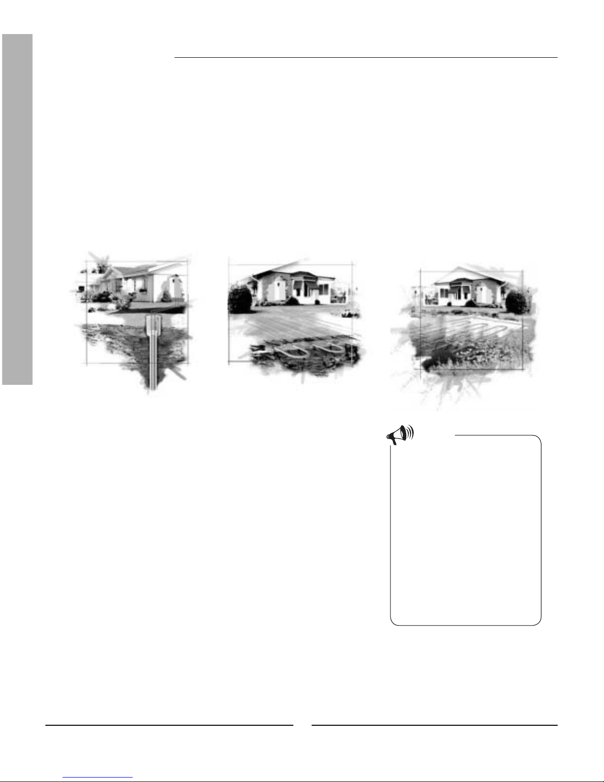
The heat pump collects stored solar energy
Boiling point in relation to the
pressure:
The boiling point of different liquids
varies with pressure, the higher the
pressure, the higher the boiling point.
For example, water boils at +100ºC
at normal pressure. Double the pressure and water boils at +120ºC. Half
the pressure and water then boils at
+80ºC. The refrigerant in the heat
pump acts in the same way, the boiling
point changes when the pressure
changes. However, the boiling point of
the refrigerant is as low as approximately -40ºC at atmospheric pressure.
Consequently, it is also suitable for
low heat source temperatures.
Note
Rock heat Soil heat Lake heat
The heat pump consists of four main parts:
1. Evaporator
Evaporates the refrigerant to gas and at the same time transfers the
heat from the heat transfer fl uid to the refrigerant circuit.
2. Condenser
Condenses the gas to fl uid again and transfers the heat to the heating
system.
3. Expansion valve
Lowers the pressure of the refrigerant.
4. Compressor
Increases the pressure of the refrigerant.
These four main parts are linked in three circuits. A refrigerant circulates
in the heat pump, which in some parts of the circuit is in a liquid state and
in other parts in a gas state. Read more about the properties of the refrigerant in the sidebar to the right.
See the detailed description of the technologies used in the heat pump on
the next page.
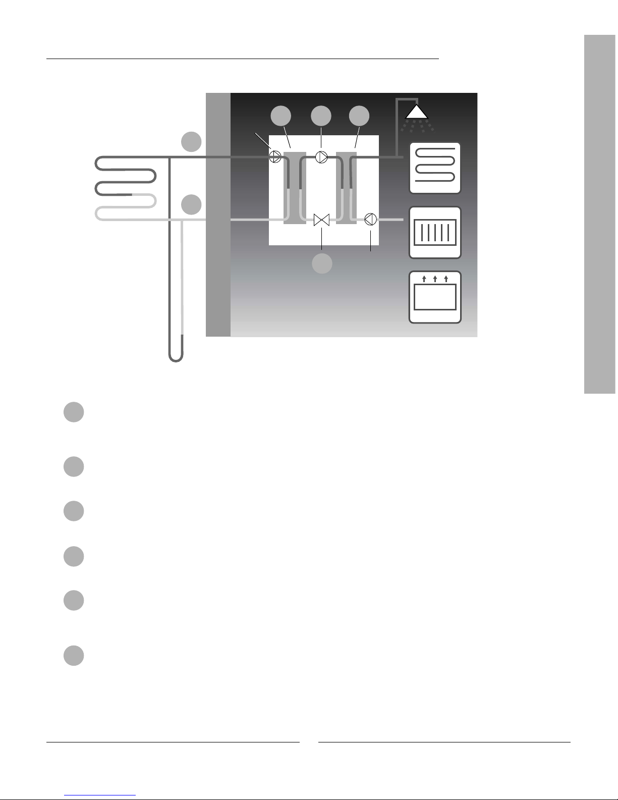
Technology in and around the heat pump
This is how your heat pump works
7
FOR THE USER
Heat transfer fl uid in. A hose is connected here that collects the stored solar energy from, e.g., the soil or
rock. The hose contains a heat transfer fl uid, which is a mixture of water and anti-freeze. The fl uid collects
the heat from the rock and with the help of the HTF pump leads it into the heat pump and the evaporator. The
temperature is then approximately 0ºC.
In the evaporator the heat transfer fl uid meets the refrigerant. At this stage the refrigerant is in a fl uid state
and is at approximately -10ºC. When the refrigerant meets the zero degree heat transfer fl uid it starts to boil.
It then forms a vapour, which is led into the compressor. The temperature of the vapour is 0ºC.
The pressure of the refrigerant increases in the compressor and the vapour temperature rises from 0ºC to
approximately +100ºC. The warm gas is then forced into the condenser.
The condenser is the heat pump's heat emitting part. Here the heat is transferred to the house’s heating
system (radiators and fl oor heating) and the hot water system. The vapour is cooled in the condenser and
becomes fl uid. The pressure in the refrigerant is still high when it is led on to the expansion valve.
The refrigerant pressure is then lowered in the expansion valve. At the same time, the temperature also drops
to approximately -10ºC. When the refrigerant has passed through the valve and the evaporator it changes to
vapour again.
In heat transfer fl uid out, the heat transfer fl uid is led out from the heat pump to the rock to collect new stored
solar energy. The temperature of the fl uid is approximately -3ºC.
1
2
3
4
5
6
Floor heating
Radiator
Fan-assisted
radiator
Heat pump
Rock
Soil
0ºC
-3ºC
0ºC +100ºC
+65ºC
+57ºC
-10ºC
1
6
2 3 4
5
Heat carrier pump
Heat
transfer pump
This is how your heat pump works
"The hot side"
"The cold side"
8
FOR THE USER
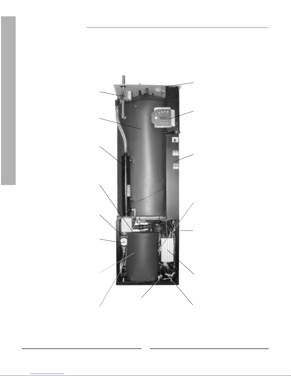
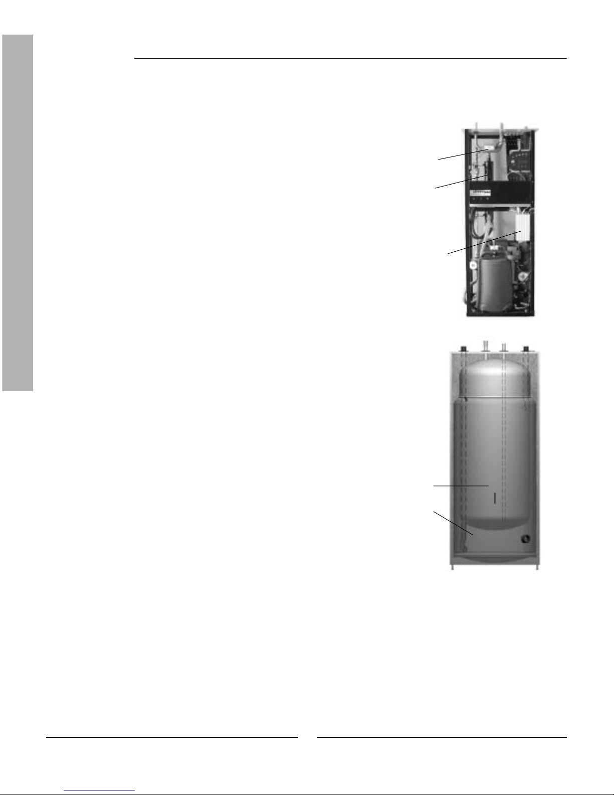
Component parts of the heat pump
Three-way valve
The valve switches between
heating the heating water and hot
water.
Hot water heater
The cylinder is double-shelled
and holds approximately 165 litres
of hot water and 60 litres of the
heating water.
Electric cassette
The electric cassette is used
to provide extra output in cold
weather conditions, with large
water consumption and at hot
water peaks.
Reset button
Press in the button if the overheat
protector on the electric cassette
has tripped. The button is located
on the side.
Heat carrier pump
The pump ensures the heating
water circulates within the heating
system.
Compressor
The compressor increases the
pressure of the refrigerant.
The temperature of the vapour
increases from 0ºC to approximately +100ºC. The compressor is
insulated to decrease the noise
level.
Socket
Connections for the mains supply
as well as sensors.
Control panel
The control panel has a background lit menu display with four
rows of text information, three
buttons and a dial.
Distribution box
The distribution box is enclosed.
It houses a reset function for the
motor cut-out as well as miniature
circuit-breakers (MCB) for the
heat pump and electric cassette.
Heat transfer fl uid pump
The pump is insulated and
features an anti-corrosive fi nish.
It ensures the heat transfer fl uid
circulates from, e.g. the rock to
the heat pump.
Control unit Rego 637
The control unit is enclosed. It
controls and monitors all heat
pump functions.
Expansion valve
Lowers the pressure of the
refrigerant that is to enter the
evaporator and collect energy
from, e.g. the rock.
Sight glass
Sight glass to check the level in the
refrigerant circuit. Air bubbles must not
form in the sight glass when the heat
pump is running. However, there might
be bubbles when the heat pump is started
and stopped.
Flexible hoses
The hoses counteract vibrations in
the heat pump.
IVT Greenline HT Plus C
Evaporator
The evaporator evaporates the
refrigerant to gas and transfers
heat from the heat transfer fl uid to
the refrigerant circuit (behind the
heat pump).
Condenser
The condenser condenses the
vapour to fl uid again and transfers
the heat to the heating system.
Component parts of the heat pump
9
FOR THE USER
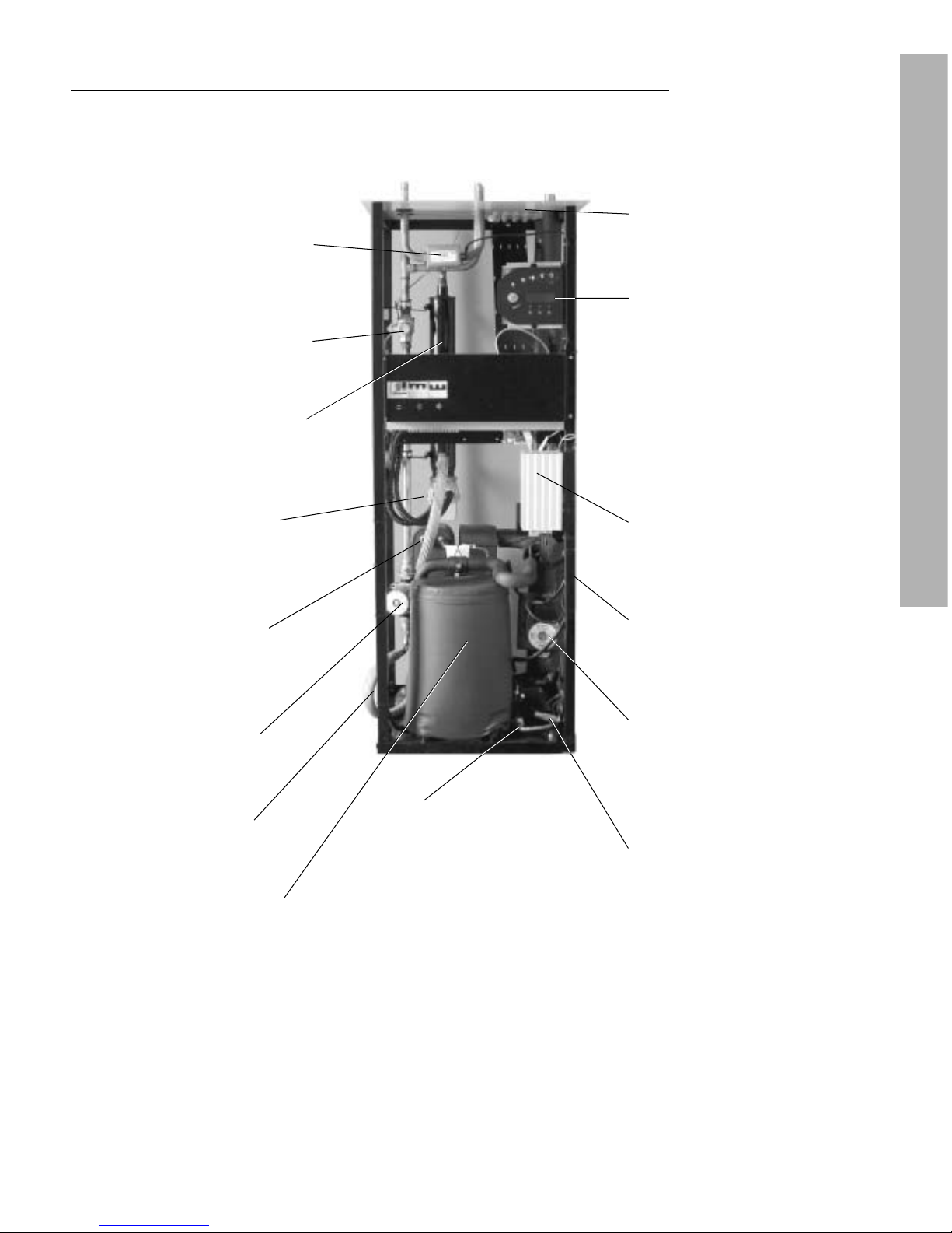
IVT Greenline HT Plus E
Reset button
Press in the button if the overheat
protector on the electric cassette
has tripped. The button is located
on the side.
Heat carrier pump
The pump ensures the heating
water circulates within the heating
system.
Compressor
The compressor increases the
pressure of the refrigerant.
The temperature of the vapour
increases from 0ºC to approximately +100ºC. The compressor is
insulated to decrease the noise
level.
Socket
Connections for the mains supply
as well as sensors.
Control panel
The control panel has a background lit menu display with four
rows of text information, three
buttons and a dial.
Distribution box
The distribution box is enclosed.
It houses a reset function for the
motor cut-out as well as miniature
circuit-breakers (MCB) for the
heat pump and electric cassette.
Heat transfer fl uid pump
The pump is insulated and features
an anti-corrosive fi nish. It ensures
the heat transfer fl uid circulates
from, e.g. the rock into the heat
pump.
Control unit Rego 637
The control unit is enclosed. It
controls and monitors all heat
pump functions.
Expansion valve
Lowers the pressure of the refrigerant that is to enter the evaporator
and collect energy from, e.g. the
rock.
Sight glass
Sight glass to check the level in the
refrigerant circuit. Air bubbles must
not form in the sight glass when the
heat pump is running. However, there
might be bubbles when the heat
pump is started and stopped.
Flexible hoses
The hoses counteract
vibrations in the heat pump.
Evaporator
The evaporator evaporates the
refrigerant to gas and transfers
heat from the heat transfer fl uid to
the refrigerant circuit (behind the
heat pump).
Particle fi lter
The fi lter can be opened for easy
cleaning. It also has a shut off
function.
Electric cassette
The electric cassette is used
to provide extra output in cold
weather conditions, with large
water consumption and at hot
water peaks.
Three-way valve
The valve switches between
heating the heating water and hot
water.
Condenser
The condenser condenses the
vapour to fl uid again and transfers
the heat to the heating system.
Component parts of the heat pump
10
FOR THE USER
Control unit Rego 637
The control unit Rego 637 is the brains of the heat pump. It makes sure the
heat pump gives the best energy savings and that it runs for many years.
The control unit controls and monitors the heating and hot water supply in
your house. The monitoring function is especially important. It shuts down
the heat pump in the event of operational disturbances so that no critical
parts are damaged.
Additional heat gives more output
When the heat pump can not manage to heat the house by itself, for
example, if there is a considerable drop in the outdoor temperature, the
control unit ensures the additional heat source is connected. Together
the heat pump and additional heat guarantee the right temperature in the
house. Additional heat in the Greenline HT Plus is provided by a built
in electric cassette. Additional heat can never completely take over the
heating from the heat pump. It only adds the output necessary for the heat
pump to be able to produce the right temperature. When the heat pump
can once again manage heating on its own the additional heat is automatically disconnected.
Hot water is given priority over heating water
In a house with water based heating a difference is made between heating
water and hot water. The heating water is for radiators/fl oor heating
and hot water is for showers and taps. Hot water is heated in a hot water
cylinder. The hot water cylinder is fi tted with a sensor that senses the
temperature of the hot water. In Greenline HT Plus C there is a hot
water cylinder inside the heat pump while Greenline HT Plus E has an
external hot water heater. The heating water passes through the hot water
cylinder’s outer shell and heats up the hot water cylinder’s inner tank. The
control unit makes sure the heating of hot water is always given priority
over the heating of the heating water. This means you never need to be
without hot water. The control unit controls a three-way valve that switches
between heating the heating water and hot water. Once the hot water
has been heated the three-way valve switches so that the heating water is
heated.
Control unit
Rego 637
Electric
cassette
(additional
heat)
Three-way
valve
Double-shelled
hot water heater
Heating water
Hot water
Control unit Rego 637

11
FOR THE USER
The control unit’s two methods to control
the heat pump
The control unit uses two different methods to control the heat pump.
These two methods are: Control with an outdoor sensor and Control with an
outdoor sensor supplemented with a room sensor.
Control with an outdoor sensor
Control with an outdoor sensor is the most common method used by the
control unit to control the heat pump. When the heat pump is delivered it
is set for this control method. A sensor is fi tted on the outside wall of the
house. It sends signals to the control unit in the heat pump. Control with
an outdoor sensor means that the heat pump automatically regulates the
heating in the house depending on the outdoor temperature. If the outdoor
temperature drops, i.e. it becomes colder; the radiators inside the house
will become warmer.
You determine the temperature of the radiators, in relation to the outdoor
temperature, with the help of a number of settings such as selecting the
heat curve on the control unit. A lower curve gives higher energy savings.
Control with an outdoor sensor supplemented
with a room sensor
Control with an outdoor sensor supplemented with a room sensor means
that you also place a sensor in a central position inside the house. This is
connected to the heat pump and provides the control unit with information
about the room temperature. The signals affect the control unit’s settings
(curves) and ensure the heat pump gives the best possible energy savings.
This control method is used when factors other than the outdoor temperature infl uence the indoor temperature. Examples include the use of a stove
or fan-assisted radiator, or if the house is sensitive to the wind.
It is only the room where the room
sensor is located that can infl uence
regulation of the temperature.
Note
Control unit Rego 637
12
FOR THE USER
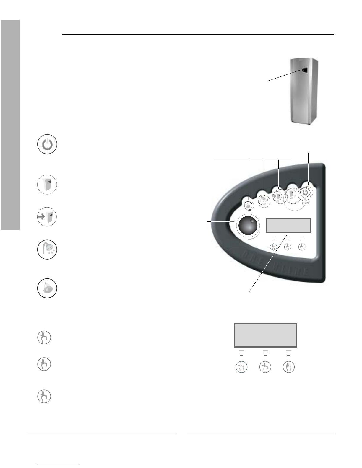
The control panel
All settings are made from the control panel. It also displays heat production statistics and information about different alarms. When you have
made your settings, the control panel makes sure they are saved in the
control unit Rego 637 to carr y out your wishes.
Control panel
Menu dial
Status lamps
Power switch (ON/OFF)
Buttons and lamps
Power switch (ON/OFF)
You start and stop the heat pump using the power
switch button.
Lamp on: The heat pump is on.
Lamp fl ashes: The heat pump is off.
Operating status
Lamp on: The heat pump (compressor) is
operational.
Additional heat status
Lamp on: The heat pump is using additional heat
from, e.g. an electric cassette.
Hot water status
Lamp on: The heat pump is heating water in the
cylinder.
Lamp fl ashes: The heat pump has a hot water
peak or is producing extra hot water.
Alarm status
Lamp fl ashes: A fault has occurred in the heat
pump.
Lamp on: The alarm has been acknowledged, but
the fault remains.
Heat
Heat
Pressing once gives a shortcut to the most
frequent temperature settings.
Info
Pressing once gives continuous information about
the heat pump’s and additional heat’s operating
conditions.
Menu
Press once to enter the main menu.
The main menu contains all setting menus and
temperature displays.
Info
Menu
Menu display
Menu buttons
Control panel
Rego 637 K1
040622 16:08:15 Tu
Heat Info Menu
Rego 637 K1
040622 16:08:15 Tu
Heat Info Menu
13
FOR THE USER
Rego 637 K1
040622 16:08:15 Tu
Heat Info Menu
Control panel
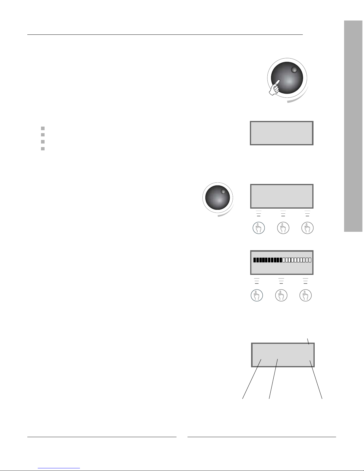
Menu dial
The menu dial is used to scroll through the menu display windows. Turn
the menu dial clockwise (to the right) to move down through the menus.
Turn the menu dial anti-clockwise (to the left) to move up through the
menus. You also determine the values of different settings by using the
dial.
The menu display gives you information and the chance to make settings.
You can:
Choose different temperature and hot water settings.
Choose extra hot water and the holiday function.
See alarm causes and receive corrective instructions.
Obtain operating statistics.
How to use the control panel
The principle of the control panel is based on the user using three
menu buttons and a menu dial to move between the different
menus and settings. On the lower row of the menu display you will
always see information about the signifi cance of the buttons. The
function of the buttons changes depending on which window you
are currently in.
Example
If, from the initial menu, you press the Heat button, you will access
the menu Temp. incr. / decr.. In this menu you can increase and
decrease the heating in the house. Note that the signifi cance of the
buttons has now changed. You can either return to the initial menu
by pressing the Return button or you can choose to change the
heating setting in the house by pressing the Adjust button. If you
press the Adjust button you can increase or decrease the heating in
the house by using the menu dial. Save your adjustment by pressing
the Save button.
Initial menu display
+
Initial menu
Initial menu
Time Date
Customer level 1
Day
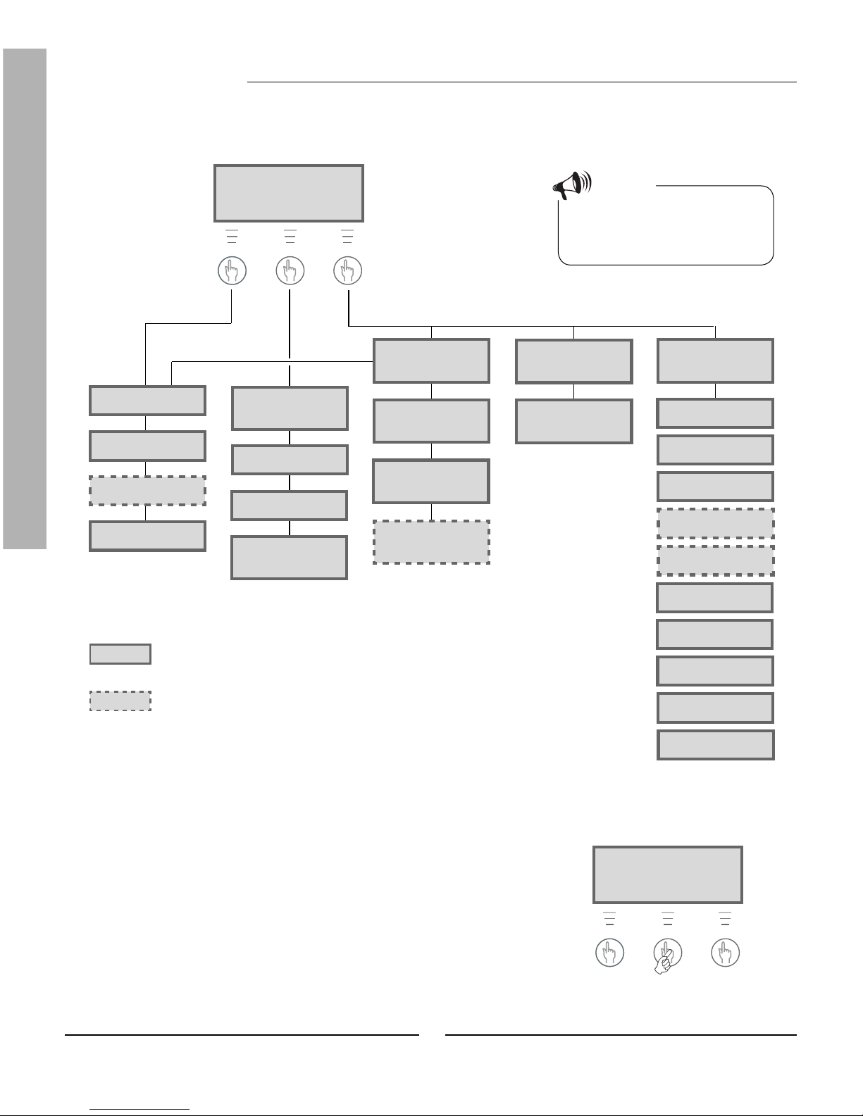
Basic functions ( Customer level 1)
Basic functions (Customer level 1) are the functions most frequently used
and the ones you have the most benefi t of. You reach the basic functions
by pressing one of the Heat, Info or Menu buttons in the initial menu.
The designation K1 in the upper right corner indicates you are in Basic
functions - Customer level 1.
Rego 637 K1
040622 16:08:15 Tu
Heat Info Menu
Rego 637 K1
040622 16:08:15 Tu
Heat Info Menu
Temp. incr. / decr.
0 5,0 10
Return Adjust
14
FOR THE USER
Basic functions - Customer level 1
The menu display is standard on all
heat pumps.
=
=
Temp. fi ne-tune
Page 17
The menu display is only shown on
the heat pump in combination with an
extra sensor or for a specifi c model of
Greenline HT Plus.
Temp. incr. / decr.
Page 16
Room temperature
Page 18
Extra hotwater
Page 18
STANDBY
No rad heat required
No hotwater required
Page 15
HOTWATER MODE
Heat pump only
Page 15
HEAT RAD MODE
Compr. + Add. heat
Page 15
HEAT RAD REQ
Heat pump starts
in #### seconds
Page 15
Main menu
Indoor temperature
settings 1
Page 19
Temperature settings
Temp. incr. / decr.
range 0-10 1.1
Page 16
Temperature settings
Temp. fi ne-tune
range -10/+10 1.2
Page 17
Temperature settings
Setting of room
temperature 1.10
Page 18
Main menu
Adjusting the hot
water settings 2
Page 19
Hot water setting
Duration of
add. hot water 2.1
Page 18
Main menu
Monitor all
temperatures 3
Page 19
Temperature readings
Return radiator GT1
Temperature readings
Out GT2
Temperature readings
Hot water GT3
Temperature readings
Shunt, fl ow GT4
Temperature readings
Room GT5
Temperature readings
Compressor GT6
Temperature readings
Heat trfl uid out GT8
Temperature readings
Heat tr fl uid in GT9
Temperature readings
Ht trfl d(coll)inGT10
Temperature readings
Httrfl d(coll)outGT11
Page 20
Note
Each menu is numbered in the lower
right-hand corner; this indicates which
main display it is associated to.
Select scrolling information on the menu
display
If you press the Info button in the initial menu you will receive continuous
information about the heat pump's operation and working temperatures.
This is what to do:
1. Press the Info button in the initial menu.
Here follows a few of the windows displayed:
Menu outline for Basic functions (Customer level 1)
Rego 637 K1
040622 16:08:15 Tu
Heat Info Menu
Rego 637 K1
040622 16:08:15 Tu
Heat Info Menu

15
FOR THE USER
The heat pump is in standby mode.
The heat pump is producing hot water. You see at which temperature
the heat pump will stop and the present temperature. Note that the stop
temperature is read at the bottom of the cylinder. The hot water is a few
degrees warmer.
The heat pump and additional heat are running.
The heat pump has received signals that it should produce heating. It now
waits for the restart time to countdown to zero.
Return to the initial menu by pressing one of the buttons or turn the dial.
Basic functions - Customer level 1
Set the heating
It is easy to set the heating level on the heat pump. However, before we
explain how to do this it is important to understand the relation between
the outdoor temperature, return temperature and heat curve slope. The
easiest way to explain the relation is with a heat curve.
Heat curve
You use the heat curve to help set the indoor temperature you would
like. The heat pump is controlled by the outdoor temperature. When the
weather becomes colder the heat pump ensures more heating is produced
automatically.
Return temperature:
The return temperature is the temperature of the water that returns to the
heat pump from the radiators. The water led out from the heat pump to the
heating system is normally 7-10ºC higher than the return temperature.
When the outdoor temperature is -10ºC and curve 4 is set, the pump
attempts to keep the return water at approximately 40ºC. If instead the
temperature is 35ºC, the fl ow water is heated until the return water is warm
enough.
Outdoor temperature:
The outdoor temperature determines how much heating the heat pump
should produce. A sensor placed outdoors sends signals to the control unit,
which then adjusts the heat pump.
Cur ve slope:
You can change the curve slope to increase or decrease the heating in the
house. The scale is between 0-10.
On delivery the heat pump curve
slope is set to position 4. This means
that the return temperature is +35ºC
when it is 0ºC outdoors.
Note
STANDBY
No rad heat required
No hotwater required
HOTWATER MODE
Heat pump only
Stop temp 53,0°
Present temp 42,0°
HEAT RAD MODE
Compr. + Add. heat
Stop temp 45,0°
Present temp 44,0°
HEAT RAD REQ
Heat pump starts
in 320 seconds

16
FOR THE USER
In cold weather (below -5ºC):
If you are not satisfi ed with the indoor temperature when it is colder than
-5ºC outdoors, you need to change the slope of the heat curve. This is what
to do:
1. Press the Heat button in the initial menu.
2. Press the Adjust button.
3. Turn the menu dial clockwise to increase the heating.
Turn the menu dial anti-clockwise to lower the heating.
(Adjust in small increments, 0.5-1.0 units is usually enough.)
4. Save the new value by pressing the Save button.
Basic functions - Customer level 1
Dashed line:
If the return temperature exceeds 57ºC an alarm is given and the compressor switches off. The heat pump star ts automatically when the return
temperature drops.
Curve slope:
2-4 Normal setting for fl oor hea-
ting.
4-6,5 Normal setting for radiators.
7-10 Abnormal high setting.
From the heat curve we see that curve slope 4 gives a return temperature
of +35ºC when it is 0ºC outdoors. If the
outdoor temperature drops we can see
that the return temperature increases.
The colder the outdoor temperature
the higher the return temperature. At
an outdoor temperature of approximately -30ºC we see the curve slope has
reached the limit value (+57ºC) for the
return temperature.
You should wait at least two days
when increasing or decreasing the
heating before making a new adjustment.
At outdoor temperatures around 0ºC
you should “adapt the heat curve” to
obtain the desired indoor temperature. Read how to “adapt the curve” in
the section Extra functions - Customer
level 2 / Temperature settings / Adapting the heat curve.
Note
Change the curve slope
The heat pump’s production of heat is adjusted by increasing or decreasing
the curve slope in the Temp. incr. / decr. menu. This is especially effective
in cold weather conditions.
Return temperature (ºC) Curve slope (0-10)
Outdoor temperature (ºC)
Temp. incr. / decr.
0 4,0 10
Return Adjust
Temp. incr. / decr.
0 5,0 10
Return Save

17
FOR THE USER
Basic functions - Customer level 1
Fine-tune the heat curve
The heat curve can also be fi ne-tuned. Fine-tuning means that you offset
the heat curve in parallel. Fine-tuning is done from the Temp. fi ne-tune
menu. The diagram for fi ne-tuning shows how the dashed line has been
offset upwards in parallel. This means the heating has been fi ne-tuned in a
positive direction and the heat pump will be instructed to maintain a higher
temperature on the return water at all outdoor temperatures.
Outdoor temperature (ºC)
Return temperature (ºC)
By using the menu dial on the control panel
the fi ne-tuning line has been moved up so the
heat pump produces more heat.
In warm weather (above +5ºC):
If you are not satisfi ed with the indoor temperature when it is warmer than
+5ºC outdoors, you should offset the cur ve in the Temp. fi ne-tune menu.
This is what to do:
1. Press the Heat button in the initial menu.
2. Turn the menu dial clockwise until you reach the menu
Temp. fi ne-tune.
3. Press the Adjust button.
4. Turn the menu dial clockwise to increase the heating.
Turn the menu dial anti-clockwise to lower the heating.
(Adjust in small increments, 0.5-1.0 units is usually enough.)
5. Save the new value by pressing the Save button.
Temp. fi ne-tune
-10° 0,0 10°
Return Adjust

18
FOR THE USER
Set the desired room temperature
If you have a room sensor connected to the heat pump you can set the
temperature in the room from the Room temperature menu. From Extra
functions (Customer level 2) you can also set how much you want the
sensor to infl uence the heating system.
This is what to do:
1. Press the Heat button in the initial menu.
2. Turn the menu dial clockwise until you reach the menu Room tempera-
ture.
3. Press the Adjust button.
4. Turn the menu dial clockwise to increase the room temperature.
Turn the menu dial anti-clockwise to lower the room temperature.
5. Save the new value by pressing the Save button.
Room temperature
10° 20,0 30°
Return Adjust
Note
The example describes how to set the
required room temperature with the
help of a connected room sensor. The
range is 10ºC to 30ºC.
Set the heat pump for extra hot water
You can obtain extra hot water by temporarily increasing the temperature
of the water in the hot water cylinder. The temperature increase is effected
with the help of the heat pump's electric cassette. A higher water temperature gives more hot water when, for example, a large number of people
wish to shower. The heat pump fi rst makes sure that the water reaches a
temperature of 50-55ºC. The electric cassette then continues to heat the
water to approximately 65ºC. You choose how long the function should run
using the Extra hotwater menu. This is what to do:
1. Press the Heat button in the initial menu.
2. Turn the menu dial clockwise until you reach the menu Extra
hotwater.
3. Press the Adjust button.
4. Turn the menu dial clockwise to choose the number of hours that the
electric cassette should be on (e.g. 24 hours).
5. Save the value by pressing the Save button.
When the set time has elapsed you
must repeat the setting to get extra
hot water again.
Note
Basic functions - Customer level 1
Extra hotwater
1h 24h 48h
Return Adjust
Extra hotwater
1h 24h 48h
Return Save

19
FOR THE USER
Basic functions - Customer level 1
Heating and hot water settings
Move to the temperature settings for heating on customer level 1 like this:
1. Press the Menu button in the initial menu.
2. Press the Select button and scroll through the heating menus with the
menu dial.
Move to the temperature settings for hot water on customer level 1 like
this:
1. Turn the menu dial clockwise until you reach the menu Adjusting the
hot water settings.
2. Press the Select button and scroll through the hot water menus using
the menu dial.
Read the temperatures on the heat pump
There are several different temperature sensors in the heat pump. Each
sensor plays an important par t in the heat pump's daily operations. It may,
for example, adjust the heat production so that the pump does not become
overheated. Proceed as follows to read the temperatures on the heat pump:
1. Press the Menu button in the initial menu.
2. Turn the menu dial clockwise until you reach the menu Monitor all
temperatures (menu 3).
3. Press the Select button.
4. Turn the menu dial to scroll through all the heat pump's temperature
sensors. See the next page.
Note
Each menu is numbered in the lower
right-hand corner; this indicates which
main display it is associated to.
Rego 637 K1
040622 16:08:15 Tu
Heat Info Menu
Main menu
Indoor temperature
settings 1
Return Select
Main menu
Adjusting the hot
water settings 2
Return Select
Main menu
Monitor all
temperatures 3
Return Select

20
FOR THE USER
All the temperature sensor menus
All the windows associated with the heat pump's temperature sensors are
presented below. Note that you cannot make any settings in these menus,
only read the current values. Some menus are standard for all models of
Greenline HT Plus while others are only available in combination with
different accessories.
The sensors give an alarm if the temperature is outside of the permitted
interval/values.
Note
All sensors are not included as
standard on the heat pump, some are
available as accessories for different
application areas. See more information under respective menus.
The menu shows the temperature in the heating system’s return, i.e. the water from the
radiators back to the heat pump in heating mode. This temperature varies depending on the
outdoor temperature.
The menu shows the outdoor temperature. Some deviation compared to the true temperature
may occur due to thermal radiation from the house to the installed outdoor sensor.
The menu shows the set and present temperature in the lower section of the outer container in
the hot water cylinder/heater. The temperature is approximately 5ºC lower than the temperature of the hot water inside the inner container.
The menu only applies together with a fl ow sensor. If an extra curve with mixing valve is used,
for example, for a fl oor heating system, you can see the temperature on the fl ow water in the
circuit. The temperature varies with the outdoor temperature.
The menu only applies together with a room sensor. The menu shows the set point value and
present temperature in the room where the sensor is fi tted.
The menu shows the compressor’s working temperature. The temperature varies between
70ºC and 125ºC during operations.
The menu shows the temperature of the radiator water as it leaves the heat pump. It varies
depending on the outdoor temperature and whether the heat pump is in hot water production
mode.
The menu shows the temperature of the water that is led into the heat pump. It varies
depending on the outdoor temperature and whether the heat pump is in hot water production
mode. The heat pump stops at 54ºC for reasons of safety.
The menu shows the temperature of the heat transfer fl uid that is led into the heat pump from
the bore hole or the ground. It can vary between -5ºC to +8ºC during a season.
The menu shows the temperature of the heat transfer fl uid that is led out of the heat pump to
the bore hole or the ground. Normally, during operations, it is 1.5 - 5.0 degrees lower than the
heat transfer fl uid that is led into the heat pump.
Basic functions - Customer level 1
Temperature readings
Return radiator GT1
Off 21,3
O
Now 21,7
O
Return
Temperature readings
Out GT2
14,0°
Return
Temperature readings
Hot water GT3
Set 51,0°
Now 46,0°
Return
Temperature readings
Shunt, fl ow GT4
Tgt 40,3° Now 43,0°
Return
Temperature readings
Room GT5
Tgt 20,0°
Now 19,5°
Return
Temperature readings
Compressor GT6
90,0°
Return
Temperature readings
Heat trfl uid out GT8
45,0°
Return
Temperature readings
Heat tr fl uid in GT9
22,0°
Return
Temperature readings
Ht trfl d(coll)inGT10
0,0°
Return
Temperature readings
Httrfl d(coll)outGT11
-4,0°
Return

21
FOR THE USER
Extra functions ( Customer level 2)
In the section Basic functions (Customer level 1) we presented the
functions that you will probably use the most and which you will receive
the most benefi t from. However, there are numerous extra functions that
you can use to control your heat pump. This can, for example, include
activating the heat pump’s holiday function or setting the time and date.
If no settings are made on Customer level 2 (K2), the menu display will
automatically return to Customer level 1 (K1) after 30 minutes. Proceed as
follows to access the extra functions on Customer level 2:
1. Press the Heat button until Access = CUSTOMER2 is displayed
2. Press the Menu button to open the Main menu. From Customer level 2
you also have access to all Customer level 1 functions.
Note
From Customer level 2 you also have
access to all the basic functions on
Customer level 1.
Only the most frequently used menus
in Customer level 2 are shown in the
menu outline. All the menus cannot be
presented due to space limitations. Use
the dial to scroll through the menus.
Press the Heat button until Access
= CUSTOMER2 is displayed.
( Initial menu)
Extra functions - Customer level 2
The menu display is standard
on all heat pumps.
=
=
The menu display is only
shown on the heat pump in
combination with an extra
sensor or for a specifi c model of
Greenline HT Plus.
Heat curve adjust.
(break) 1.3
Page 22
Main menu
Indoor temperature
settings 1
Page 23
Mix. valve incr/decr
range 0-10 1.5
Page 23
Mix. valve fi ne-tune
range -10/+10 1.6
Page 23
Adjusting mix. valve
curve (break) 1.7
Page 23
Setting of room
sensor infl 1.11
Page 22
Setting of holiday
function 1.12
Page 22
Remote control
temperature 1.13
Page 22
Setting of summer
disconnection 1.14
Page 22
Main menu
Adjusting the hot
water settings 2
Page 24
Interval for
hot water peak 2.2
Page 24
Main menu
Timer control
settings 4
Page 24
Clock setting HP
accord. to clock 4.1
Page 24
Setting level
heat pump +/- 4.1.1
Page 25
Clock setting DHW
accord. to clock 4.3
Page 25
Main menu
Op. time readings on
HP and add. heat 7
Page 25
Heat pump in operat.
number of hours? 7.1
Page 26
Add. heat in operat.
number of hours? 7.3
Page 26
Distribut. add. heat
DHW-Rad in % 7.4
Page 26
Main menu
Clock, setting
time and date 10
Page 27
Main menu
Alarm logging
of all alarms 11
Page 27
Main menu
Return to
factory settings 12
Page 27
Menu outline for Extra functions (Customer level 2)
Rego 637 K2
040622 16:08:15 Tu
Heat Info Menu
Rego 637 K2
040622 16:08:15 Tu
Heat Info Menu
Distribution HP
DHW-Rad in % 7.2
Page 26

22
FOR THE USER
Temperature settings
Proceed as follows to access the temperature settings for the heating on
Customer level 2:
1. Press the Heat button until Access = CUSTOMER2 is displayed.
2. Press the Menu button.
3. Press the Select button and scroll through the menus with the menu
dial.
Adapting the heat curve
You can "break" the heat curve up or down every fi fth outdoor degree.
For example, you can make a hump in the curve at 0ºC. The purpose of
breaking the curve is to be able to infl uence the heat pump's heat production at extra sensitive outdoor temperatures.
Room sensor infl uence
The menu is only shown for heat pumps having a room sensor installed.
You use the menu to set how much the room sensor shall infl uence the
heat curve. A higher value will have a greater effect. Please note that the
room sensor only fi ne-tunes the heat curve. Consequently, it is impor tant
the basic setting of the heat curve’s slope and fi ne-tuning are correct.
Holiday function
The menu is only shown for heat pumps having a room sensor installed.
The holiday function gives you the possibility to choose a number of days
when the room temperature will be lowered to 15ºC (the temperature is
not adjustable). When the days have passed the heat pump returns to the
normal heating setting. Hot water production is not affected by the holiday
function.
Remote control
The menu is only shown for heat pumps having a room sensor installed. In
addition, special remote control equipment is needed. This equipment is
available as an accessory. You can switch between the remote control mode
and normal mode using a telephone.
Summer disconnection
The function means the heat pump only produces hot water when the
outdoor temperature rises above the set value.
Extra functions - Customer level 2
Main menu
Indoor temperature
settings 1
Return Select
Temperature settings
Heat curve
adjust. (break) 1.3
Return Select
Temperature settings
Setting of room
sensor infl . 1.11
Return Select
Temperature settings
Setting of holiday
function 1.12
Return Select
Temperature settings
Remote control
temperature 1.13
Return Select
Temperature settings
Setting of summer
disconnection 1.14
Return Select

23
FOR THE USER
Set extra heat curve with mixing valve
If you have fl oor heating combined with radiators you should set an extra
heat curve with mixing valve. The mixing valve is a valve that lets water
through in different amounts. It prevents the fl oor from becoming too hot
and destroying the fl ooring. The menu is only displayed when there is an
extra fl ow sensor, T4 (GT4), on the heat pump. You set the extra heat cur ve
using two menus: Mix. valve incr/decr and Mix. valve fi ne-tune.
Increase or decrease the mixing valve
1. Press the Heat button until Access = CUSTOMER2 is displayed.
2. Press the Heat button.
3. Turn the menu dial clockwise until you reach the menu Mix. valve
incr/decr.
4. Press the Adjust button.
5. Turn the menu dial clockwise to choose a higher heat curve.
Turn the menu dial anti-clockwise to choose a lower heat curve.
6. Save the new value by pressing the Save button.
Note
The initial position of the fl oor heating circuit is heat curve 2.
The scale covers the range 0 to 10.
Extra heat curve with mixing valve
only works with an extra fl ow sensor
T4 (GT4).
Fine-tune the mixing valve
1. Press the Heat button until Access = CUSTOMER2 is displayed.
2. Press the Heat button.
3. Turn the menu dial clockwise until you reach the menu Mix. valve
fi ne-tune.
4. Press the Adjust button.
5. Turn the menu dial clockwise to set an upward, parallel offset on the
curve.
Turn the menu dial anti-clockwise to set a downward parallel offset on
the curve.
6. Save the new value by pressing the Save button.
Note
In the example we describe how to
fi ne-tune the extra heat cur ve. The
scale covers the range -10ºC to +10ºC.
Extra functions - Customer level 2
Mix. valve incr/decr
0 2,0 10
Return Adjust
Mix. valve fi ne-tune
-10° -0,0° 10°
Return Adjust

24
FOR THE USER
Timer control
Open the setting menus for timer control like this:
1. Press the Heat button until Access = CUSTOMER2 is displayed.
2. Press the Menu button.
3. Turn the menu dial clockwise until you access the menu Timer control
settings (menu 4).
4. Press the Select button and scroll through the menus using the menu
dial.
Clock setting of the heat pump according to clock
The function Clock setting HP accord. to clock is for those who want the heat
pump to produce different amounts of heat at different times of the day
and on different days of the week. This allows you to make further energy
savings.
Example:
You want to set the heat pump so that it maintains a 5ºC lower radiator
temperature on Mondays between 22:00 and 06:00.
1. Turn the dial clockwise until you access the menu Clock setting HP
accord. to clock (menu 4.1).
2. Press the Select button.
3. Turn the menu dial clockwise to choose the day. Now press the Adjust
button to select the weekday with the symbol ^. Turn the menu dial
clockwise one step to activate the start day. The weekday now has a
capital letter.
4. Press the right-hand arrow (->) until the cursor reaches the fi rst two
zeros (00).
Extra functions - Customer level 2
Hot water settings
Hot water peak
Recurring increase in the hot water temperature
The Interval for hot water peak menu is used to set the interval for a
recurring increase in the hot water temperature. If, for example, you set
the value seven days, the temperature is increased once a week to approximately 65ºC.
Hot water setting
Interval for
hot water peak 2.2
Return Select
Main menu
Indoor temperature
settings 1
Return Select
Main menu
Timer control
settings 4
Return Select
Clock setting
Clock setting HP
accord. to clock 4.1
Return Select
Clock setting HP 1
mo 00:00-00:00
Return Adjust
>
Clock setting HP 1
Mo 00:00-00:00
Return ->
>
Clock setting HP 1
Mo 00:00-00:00
Return ->
>
>

25
FOR THE USER
5. Turn the menu dial until the value 22:00 is displayed.
6. Press the right-hand arrow twice (->) to move the cursor two steps to
the right.
7. Turn the menu dial until the value 06:00 is displayed.
8. Press the right-hand arrow so it is replaced by the Save function.
9. Finish the setting by pressing the Save button.
10. Press the Return button.
11. Turn the menu dial clockwise until you reach the menu Setting level
heat pump +/- (menu 4.1.1).
12. Press the Select button and set the temperature to -5ºC, which is to
apply for the chosen time zone.
13. Finish by pressing the Save button.
Note
If you would like to make the setting
for every day of the week, carry out
the instruction shown in the example
seven times, once for each weekday.
The temperature set under 4.1.1
applies to all active time zones.
Clock setting of the hot water according to clock
The Clock setting DHW accord. to clock (menu 4.3) works in exactly the
same way as Clock setting HP accord. to clock (menu 4.1). You can choose
to completely disable hot water heating to save energy. This is primarily
effective when peak tarif fs are charged. The procedure is the same as in
the previous example. Use this to make your settings.
Reading operating times on the heat pump
and additional heat
Statistics concerning the heat pump and additional heat operations are
stored in the control unit. For example, you can see how many hours they
have been running. To view the operating times for the heat pump and
additional heat:
1. Press the Heat button until Access = CUSTOMER2 is displayed.
2. Press the Menu button.
Extra functions - Customer level 2
Clock setting HP 1
Mo 22:00-06:00
Return <- ->
Clock setting HP 1
Mo 22:00-06:00
Return <- Save
Clock setting HP 1
Setting level heat
pump +/- 4.1.1
Return Select
Clock setting
Clock setting DHW
accord. to clock 4.3
Return Select
Main menu
Indoor temperature
settings 1
Return Select
>
>

26
FOR THE USER
3. Turn the menu dial clockwise until you reach the menu Op time
readings on HP and add. heat (menu 7).
4. Press the Select button and scroll through the menus using the menu
dial.
The number of hours the heat pump has been in
operation
The menu shows the number of hours that the heat pump has been in
operation since the day of installation.
The heat pump’s hot water mode and heating
mode operations as a percentage
The menu show the heat pump's allocation between hot water mode and
heating mode. The allocation is stated as a percentage. Heating mode
refers to heating of the radiator water.
The number of hours additional heat has been in
operation
The menu shows the number of hours additional heat has been in
operation since the day of installation.
Additional heat’s hot water mode and heating
mode operations as a percentage
The menu shows the heat addition's allocation between hot water mode
and heating mode. The allocation is stated as a percentage. Heating mode
refers to heating of the radiator water.
Set the time and date
The heat pump has functions that are dependent on both the clock and
date. Thus it is important that these are correct. This is how you access the
menu Clock, setting time and date:
1. Press the Heat button until Access = CUSTOMER2 is displayed.
2. Press the Menu button.
Extra functions - Customer level 2
Main menu
Op. time readings on
HP and add. heat 7
Return Select
Op. time readings
Heat pump in operat.
number of hours? 7.1
Return Select
Op. time readings
Distribution HP
DHW-Rad in % 7.2
Return Select
Op. time readings
Add. heat in operat.
number of hours? 7.3
Return Select
Op. time readings
Distribut. add. heat
DHW-Rad in % 7.4
Return Select

27
FOR THE USER
3. Turn the menu dial clockwise until you reach the menu Clock, setting
time and date (menu 10).
4. Press the Select button and make your settings using the menu dial
and menu buttons.
Alarms given by the heat pump
You can easily see any alarms given by the heat pump. The menu provides
you with information about the alarm type and when it occurred. If there is
an asterisk (*) in the menu window this means the alarm is still active, i.e.
the cause of the alarm remains. This is how you access the Alarm logging
of all alarms (menu 11):
1. Press the Heat button until Access = CUSTOMER2 is displayed.
2. Press the Menu button.
3. Turn the menu dial clockwise until you reach the menu Alarm logging
of all alarms (menu 11).
4. Press the Select button and scroll using the menu dial between any
alarms that may have previously occurred. Alarms are stored in
chronological order. Read more about the heat pump's alarms under
the heading All alarms.
Return to factory settings
If you want to restore the factory settings on the heat pump you can easily
reset all the settings you have made. This is how you access the Return to
factory settings menu (menu 12):
1. Press the Heat button until Access = CUSTOMER2 is displayed.
2. Press the Menu button.
3. Turn the menu dial clockwise until you reach the menu Return to
factory settings (menu 12).
4. Press the Select button.
5. Return to the factory settings by pressing the Yes button.
When you return to the factor y settings all the adjustments made on
customer levels 1 and 2 are reset such as temperature settings and
time control settings.
Extra functions - Customer level 2
Main menu
Clock, setting
time and date 10
Return Select
Main menu K2
Indoor temperature
settings 1
Return Select
Main menu K2
Indoor temperature
settings 1
Return Select
Main menu
Alarm logging
of all alarms 11
Return Select
Main menu
Return to
factory settings 12
Return Select

28
FOR THE USER
Maintenance
Your heat pump requires a minimum of maintenance, however, we still
recommend some servicing to get optimal performance from your heat
pump. Check the following items a few times during the fi rst year. You
should then check them once or twice a year:
Sight glass
Expansion vessel
Particle fi lter
Protective anode (only models with a stainless steel hot water cylinder)
Maintenance inside the heat pump
Make sure you disconnect the main power supply before opening the heat
pump. Turn off the power switch that precedes the heat pump.
Opening the front cover
On certain models you will need to open the front cover to access some
of the maintenance areas, e.g. the sight glass and particle fi lter. The front
cover is secured at the top by two screws.
This is how you remove the front cover from the heat pump:
1. Unscrew the two screws on the top. See the picture.
2. Tilt the front cover towards you.
3. Lift the front cover up to release the lower edge.
Sight glass
Sometimes when the heat pump has started you can see the fl uid in the
refrigerant circuit bubble for a few minutes in the sight glass. This is
completely normal. However, if it bubbles continuously you should contact
your dealer.
War ning
For reasons of safety the main power
supply must be disconnected before
working on the heat pump.
Only an accredited refrigeration
company is permitted to work on the
heat transfer fl uid circuit.
Remove the front cover by unscrewing the
screws on the top.
Sight glass
Greenline HT Plus E
If the sight glass shows green this means there is no moisture in the
system. If it is yellow there is moisture in the system. If this happens,
contact your dealer.
Maintenance

29
FOR THE USER
Expansion vessel
A plastic expansion vessel is connected to the heat pump heat transfer
circuit (cold side). The level in the vessel should not fall below the
minimum level 1/3. If the fl uid level is too low, contact your dealer. After
discussions with your dealer fi lling can take place as set out below:
The heat pump must be in operation all the time while fi lling.
1. Remove the cover on the valve on top of tank. Now carefully open the
valve (fi gure 1).
2. Check that the valve is fully open (fi gure 2).
3. Fill with anti-freeze or water (to 2/3) with the help of a clean watering
can or the like (fi gure 3).
4. Close the valve and fi nish by screwing on the cover (fi gure 4).
Particle fi lter
The task of a particle fi lter is to ensure no particles or dirt enter the
heat exchangers. Over time the fi lter can become clogged and will need
cleaning. There are particle fi lters on both the hot and cold sides. To clean
the particle fi lters:
1. Shut down the heat pump using the ON/OFF button.
2. Close the valve and unscrew the sealing cap.
3. Loosen the circlip holding the screen in the valve. Use the supplied
circlip pliers.
4. Lift out the screen from the valve and wash clean with water.
5. Refi t the screen, the circlip and sealing cap.
6. Open the valve and start the heat pump using the ON/OFF button.
On the cold side the particle fi lter
is located outside of the heat pump.
It may be concealed by insulation
material or a black box.
On Greenline HT E Plus the hot
side’s particle fi lter is fi tted inside the
heat pump. On Greenline HT Plus C
it is located outside of the heat pump.
Note
Strainer Circlip Sealing cap
max. level
min. level
Figure 1 Figure 2 Figure 3 Figure 4
Particle fi lter
Greenline HT Plus E
Maintenance

30
FOR THE USER
Control box with diode lamps
Electronic anode
Checking the protective anode
Checking the protective anode only applies to stainless steel hot water
cylinders. At the top of the hot water cylinder, under the insulation, there is
a protective anode. The task of the anode is to prevent corrosion so the hot
water cylinder does not corrode away. The hot water cylinder must be fi lled
with water in order for the protective anode to work.
There are two types of protective anodes: a sacrifi cial anode and an
electronic anode.
Sacrifi cial anode
The sacrifi cial anode can corrode depending on the water quality. If the
diameter of the anode has been reduced to a few millimetres it must be
replaced. This is how you check the sacrifi cial anode:
1. Shut off the main cold water supply.
2. Open a tap and let the water run out to reduce the pressure in the hot
water cylinder.
3. Unscrew the anode from the heat pump and check its diameter.
Electronic anode
If the protective anode is electronic there is a control box showing the
status of the anode. The diode lamps are either green or red. If green, the
protective anode is operating and working normally. Red can indicate a
fault. When large amounts of hot water are used (e.g. with a bath) the lamp
may show red for a short period without there being a fault. However, if the
red light is on for more than ten hours this indicates the anode is faulty and
you should contact your dealer. If the fault occurs at the weekend you can
wait to the next working day before contacting your dealer.
If the diameter of the anode has been
reduced to a few millimetres it must
be replaced as soon as possible.
Note
Sacrifi cial anode
Maintenance

31
FOR THE USER
Lower the heating.
Open the thermostat valves completely.
Savings
The heat pump's task is to produce heating of the house as cost-effectively
as possible. You can infl uence operating costs by your own settings for the
heat pump. In addition you can infl uence your energy savings by, e.g.
Lowering the indoor temperature.
Opening thermostat valves completely.
Lowering the indoor temperature
The lower the indoor temperature the better the heating economy. So
make sure you do not set the heat curve too high. Use your heating system
in the best possible way by keeping the entire surface of radiators or fl oor
coils warm.
1. Seal windows and doors, but not too tight.
2. When you air the room, do it quickly and with a cross draught.
Opening thermostat valves completely
The thermostat valves on radiators and fl oor coils can have a negative
effect on the heating system by slowing the fl ow and, by doing so, the heat
pump must compensate with a higher temperature. If thermostat valves
are installed they should be opened fully, except in bedrooms or other
areas where a lower temperature is required. In these rooms they can be
somewhat closed.
Savings

32
FOR THE USER
ALARM
Power failure
040622 16:08:15
Info Ackn.
What to do if a fault occurs
The control unit has an advanced monitoring system that gives alarms if
anything unforeseen happens in the heat pump. Most alarms are rectifi ed
by you the user and there is never any risk that you can damage anything
in the heat pump when you reset an alarm.
If a room sensor is installed the lamp on this will come on when the heat
pump gives an alarm.
Example of an alarm:
Info button:
When you press the Info button and turn the menu dial, information is
displayed as well as possible actions to rectify the alarm.
Ackn. button:
When you press the Ackn. button the alarm lamp on the control panel goes
out and the heat pump starts again within 15 minutes if there is a heating
requirement. If the fault has not been rectifi ed the lamp will remain lit.
Should several alarms have occurred on the heat pump, turn the menu dial
clockwise to fi nd out more information about each alarm.
Cause.
Date when the
alarm occurred.
Time when the alarm occurred.
Info Acknowledge
Dimmed menu display
Possible cause 1: Blown fuse in the house’s fuse box/distribution
box.
Action: 1. Check the fuses in the house’s fuse box.
2. Replace the fuse if necessary. If miniature circuit
breakers have tripped these are reset by pushing
up the toggle switch.
3. The heat pump automatically returns to its
operating mode 15 minutes after the fault has
been rectifi ed.
Possible cause 2: The heat pump's miniature circuit-breaker has
tripped.
Action: 1. Reset the heat pump's miniature circuit-breaker
by pushing up the centre toggle switch.
2. The heat pump automatically returns to its
operating mode 15 minutes after the fault has
been rectifi ed.
Miniature circuitbreaker for
Greenline HT Plus C
Miniature circuitbreaker for
Greenline HT Plus E
Note
For technical reasons the heat pump
does not restart until 15 minutes after
a stoppage.
What to do if a fault occurs

33
FOR THE USER
Fuses and reset buttons on the heat pump
Fuse 4
Reset button for the electric cassette
overheat protection.
NOTE! The button must be pressed
in fi rmly.
Fuse 1
Reset switch for motor cut-out
compressor.
Fuse 2
Reset switch for the heat pump’s
miniature circuit-breaker.
Fuse 3
Reset switch for the electric
cassette’s miniature circuit-breaker.
Sight glass
Particle fi lter
Cleanable, with shutoff switch.
Greenline HT Plus C
Greenline HT Plus E
Sight glass
What to do if a fault occurs
Motor cut-out compressor
Motor cut-out HTF pump
Compressor temperature
Low pressure switch
High pressure switch
Electric cassette
Power failure
Phase sequence error
High return to the heat pump
Heat transfer fl uid out max
High heat transfer fl uid delta
Sensor fault
Heat transfer fl uid in under limit and heat
transfer fl uid out under limit
List of all alarms:
All alarms
An alarm can sometimes occur temporarily due to various reasons.
However, there is never a risk involved in resetting an alarm. All
the alarms that can appear in the menu display are described on
the following pages. The descriptions give you an idea about the
nature of the alarm and what you can do to rectify it. The text often
refers to different fuses and reset buttons on the heat pump. These
are shown in the fi gures above.

34
FOR THE USER
Motor cut-out compressor (MB1)
Possible cause 1: Intermittent fault or overload on the power
supply.
Action: 1. Press the Ackn. button.
The alarm indication goes out even if the fault has
not been rectifi ed.
2. Press in the motor cut-out button on the heat
pump. (Fuse 1).
3. Wait for the heat pump to start.
Possible cause 2: Current level (A) on the motor cut-out is set too
low.
The current drawn by the compressor varies during
summer/winter operations.
Action: 1. Contact your dealer.
Possible cause 3: Contactor or cut-out faulty, or loose electrical
connections to the compressor.
Action: 1. Contact your dealer.
Possible cause 4: Compressor error.
Action: 1. Contact your dealer.
Motor cut-out HTF pump (MB2)
(Applies to models C11, E11, E14 and E17)
Possible cause 1: The HTF pump is blocked due to contamination.
Action: 1. Press the Ackn. button.
2. Loosen the venting screw and remove the dirt.
3. Help to start the pump with a screwdriver.
The alarm indication goes out even if the fault has
not been rectifi ed.
Possible cause 2: Faulty electric motor on HTF pump.
Action: 1. Contact your dealer.
Possible cause 3: Temporar y error.
Action: 1. Contact your dealer should repeated faults occur.
The menu display shows:
What to do if a fault occurs
ALARM (MB1)
Compr. circ. Switch
040622 16:08:15
Info Ackn.
The menu display shows:
ALARM (MB2)
HTF c-pump switch
040622 16:08:15
Info Ackn.
The reset switch for the compressor
can be found under heading Fuses
and resetting buttons on the heat
pump.
Note
The alarm indication goes out when
acknowledging the alarm even if the
fault has not been rectifi ed.
Note

35
FOR THE USER
LP in the menu display stands for low
pressure switch.
Note
Low pressure switch (LP)
Possible cause 1: Air in the heat transfer system.
Action: 1. Press the Ackn. button.
2. Check the expansion vessel.
3. Fill with fl uid if necessary.
4. Listen for air in the system. If air is heard constantly, contact your dealer.
Possible cause 2: The particle fi lter on the cold side is clogged.
Action: 1. Check the particle fi lter.
2. Clean the particle fi lter if necessary.
3. Press the Ackn. button.
Possible cause 3: Lack of refrigerant in the heat transfer circuit.
Action: 1. Press the Ackn. button.
2. Wait for the heat pump to start.
3. Check whether it bubbles continuously in the
sight glass.
4. If it bubbles continuously, contact your dealer.
Possible cause 4: The HTF pump has stopped or is set at too low a
speed.
Action: 1. Press the Ackn. button.
2. Check that the pump has not stopped or is set at
the wrong speed.
Possible cause 5: Ice formation in the heat exchanger due to a
lack of anti-freeze in the heat transfer circuit.
Action: 1. Contact your dealer.
Possible cause 6: Faulty expansion valve (the alarm appears in
time periods of 3-4 weeks).
Action: 1. Contact your dealer.
Compressor temperature T6 (GT6)
Possible cause 1: The working temperature of the compressor is
too high.
Action: 1. Press the Ackn. button.
2. Contact your dealer at repeated alarms.
Possible cause 2: Intermittent temperature rise due to abnormal
operating conditions
Action: 1. Press the Ackn. button.
2. Wait and see.
What to do if a fault occurs
The menu display shows:
ALARM (GT6)
Compr. superheat
040622 16:08:15
Info Ackn.
The menu display shows:
ALARM (LP)
Low pressure switch
040622 16:08:15
Info Ackn.

36
FOR THE USER
Pressure switch high (HP)
Possible cause 1: Air in the heating system.
Action: 1. Press the Ackn. button.
2. Check whether there is air in the radiators.
3. Fill the heating system and vent if necessary.
Possible cause 2: Not enough fl ow over the heat pump.
Action: 1. Press the Ackn. button.
2. Check that the heat carrier pump has not
stopped.
3. Check that all the valves are open. The thermostat valves in heating systems should be fully
open and in fl oor heating systems at least half of
the coils should be fully open.
4. Possibly increase the speed of the heat carrier
pump.
Possible cause 3: The particle fi lter on the hot side is clogged.
Action: 1. Press the Ackn. button.
2. Check the fi lter.
3. Clean the fi lter if necessary.
Possible cause 4: The refrigerant circuit is overfi lled.
Action: 1. Contact your dealer.
Possible cause 5: The dr ying fi lter is clogged.
Action: 1. Contact your dealer.
HP in the menu display stands for
high pressure switch.
Note
Increase the speed of the heat carrier pump:
Use a screwdriver or a coin to increase
the speed of the heat carrier pump.
Turn one step anti-clockwise.
Note
Electric cassette (EK)
Possible cause 1: The electric cassette 's miniature circuit-breaker
has tripped.
Action: 1. Press the Ackn. button.
2. Reset the miniature circuit breaker button on the
heat pump (circuit breaker 3) by pushing up the
toggle switch.
3. Contact your dealer if the miniature circuit
breaker trips again.
Possible cause 2: The electric cassette’s overheat protection has
tripped.
Action: 1. Press the Ackn. button.
2. Reset the overheat protector (circuit breaker 4)
by pressing in the button on the electric cassette’s
protective casing. The circuit breaker is reset
when you hear a clicking sound.
3. Check that the particle fi lter on the hot side is
clean.
The miniature circuit-breaker button
for the electric cassette can be found
under the heading Fuses and reset but-
tons on the heat pump.
The most frequent cause for the overheat protection tripping is a poor fl ow
over the electric cassette, which can
be due to air in the heat pump or that
the particle fi lter is clogged.
Note
What to do if a fault occurs
The menu display shows:
ALARM (HP)
High press. switch
040622 16:08:15
Info Ackn.
The menu display shows:
ALARM (EK)
Electrical cassette
040622 16:08:15
Info Ackn.

37
FOR THE USER
Power failure
The heat pump maintains all its settings in case of a power failure. When
the power returns the heat pump automatically starts up according to the
previous settings.
Possible cause: One or two phases to the heat pump are down.
Action: 1. Check that the fuses in the house’s distribution
box have not blown.
2. Change the fuse if necessary. If you have
miniature circuit-breakers and these have tripped
you reset them by pushing up the toggle switch.
3. The heat pump automatically returns to operating
mode once the fault has been rectifi ed.
Phase sequence fault
Possible cause 1: One or two phases to the heat pump are down.
Action: 1. Check that the fuses in the house’s distribution
box have not blown.
2. Change the fuse if necessary. If you have
miniature circuit-breakers and these have tripped
you reset them by pushing up the toggle switch.
3. The heat pump automatically returns to operating
mode once the fault has been rectifi ed.
Possible cause 2: Phase sequence to the heat pump is incorrect.
(The alarm may only be rectifi ed by an electrician.)
Action: 1. Press the Ackn. button.
2. Switch the phase sequence on the incoming
supply.
The heat pump starts automatically once the phase
sequence has been switched.
High Heat transfer fl uid delta T8/T9 (GT8/GT9)
The heat pump gives an alarm when the temperature difference between
the sensors T8 (GT8) and T9 (GT9) is too high.
Possible cause 1: Not enough fl ow over the heat pump.
Action: 1. Check that the heat carrier pump has not
jammed.
2. Check that all the valves are open. The thermostat valves in heating systems should be fully
open and in fl oor heating systems at least half of
the coils should be fully open.
Possible cause 2: The particle fi lter on the hot side is clogged.
Action: 1. Clean the particle fi lter.
What to do if a fault occurs
If the power does not return on all phases at the same time during external
electrical work, there is a risk that the
Rego control unit gives a false alarm
for a phase sequence error.
Note
The menu display shows:
ALARM
Power failure
040622 16:08:15
Info Ackn.
The menu display shows:
ALARM
3-phase incorrect
040622 16:08:15
Info Ackn.
The menu display shows:
ALARM GT8/GT9
High HTF delta
040622 16:08:15
Info Ackn.

38
FOR THE USER
Heat transfer fl uid out max T8 (GT8)
There is a sensor T8 (GT8) in the heat pump, which for reasons of safety,
stops the compressor if the temperature of the water going out to the
radiators becomes too high.
Possible cause 1: Not enough fl ow over the heat pump.
Action: 1. Check that the heat carrier pump has not
jammed.
2. Check that all the valves are open. The thermostat valves in heating systems should be fully
open and in fl oor heating systems at least half of
the coils should be fully open.
Possible cause 2: The particle fi lter on the hot side is clogged.
Action: 1. Clean the particle fi lter.
The heat pump starts automatically
when the alarm is reset and the water
temperature has dropped to its normal
value.
Note
High return to the heat pump T9 (GT9)
There is a sensor T9 (GT9) in the heat pump, which for reasons of safety,
stops the compressor if the temperature of the return water from the
radiators becomes too high. The limit lies at approximately 58ºC.
Possible cause 1: The heating setting is too high.
Action: 1. Lower the heating setting (Temp. incr. / decr.).
Possible cause 2: The valves on the radiators or fl oor heating
system are closed.
Action: 1. Open all valves.
2. Press the Ackn. button.
Possible cause 3: The hot water temperature is set too high.
Action: 1. An alarm is given in hot water mode.
Contact the installer to adjust the hot water
temperature.
Possible cause 4: The fl ow across the heat pump is greater than
the fl ow in the heating system.
(Only applies if a bypass is fi tted.)
Action: 1. Reduce the speed of the heat carrier pump or
increase the speed of the main pump in the
heating system.
2. Contact your dealer.
What to do if a fault occurs
The heat pump starts automatically
when the temperature drops.
Lower the speed of the heat carrier
pump:
Use a screwdriver or a coin to lower the
speed of the heat carrier pump. Turn
one step clockwise. The lowest speed
should be avoided.
Note
The menu display shows:
ALARM (GT9)
High return HP
040622 16:08:15
Info Ackn.
The menu display shows:
ALARM (GT8)
HTF out max
040622 16:08:15
Info Ackn.

39
FOR THE USER
HTF in under limit T10 (GT10) and HTF out
under limit T11 (GT11)
Possible cause 1: Temporar y low heat transfer fl uid temperature.
Action: 1. Wait and see.
2. If the alarm returns, contact your dealer.
Possible cause 2: Too low fl ow on the cold side.
Action: 1. Check the particle fi lter.
2. Clean the fi lter if it is clogged with dir t.
Possible cause 3: The minimum heat transfer fl uid temperature
has been set too low.
Action: 1. Wait and see.
2. If the alarm returns, contact your dealer.
In a groundwater system the cause may also be:
Possible cause 4: Clogged fi lter in the groundwater circuit.
Action: 1. Clean the fi lter.
Possible cause 5: The motor cut-out or a fuse on the pump in the
groundwater system has tripped.
Action: 1. Reset the motor cut-out or fuse.
Possible cause 6: Faulty pump in the groundwater circuit.
Action: 1. Contact your dealer.
Sensor fault
All sensors connected to the heat pump can give an alarm when defective.
In the example to the right it is sensor T1 (GT1), Return radiator, which
has given an alarm. All sensors give alarms in the same way. Read more
about the sensors under heading All the temperature sensor menus.
Possible cause 1: Temporar y error.
Action: 1. Wait and see.
Possible cause 2: Short circuit or broken sensor cable.
Action: 1. If you have an ohmmeter you can disconnect the
sensor and check the cable’s resistance. Compare
with the sensor table in the section Technical
information. Otherwise contact your dealer.
Possible cause 3: Defective sensor or incorrect connection.
Action: 1. Contact your dealer.
Switch off the power before checking
the resistance of the cable.
Note
What to do if a fault occurs
The menu display shows: e.g.
ALARM (GT1)
Sensor return rad.
040622 16:08:15
Info Ackn.
The menu display shows:
ALARM (GT10)
HTF in under limit
040622 16:08:15
Info Ackn.
The menu display shows:
ALARM (GT11)
HTF out under limit
040622 16:08:15
Info Ackn.

40
INDEX
Technical information
The heat pump's factory settings
The table shows the factory settings for all the settings that can be
changed by the installer.
Sensor table
The table shows all sensor resistance
at different temperatures.
Temperature (ºC) kΩ
-40 154.300
-35 111.700
-30 81.700
-25 60.400
-20 45.100
-15 33.950
-10 25.800
-5 19.770
0 15.280
5 11.900
10 9.330
15 7.370
20 5.870
25 4.700
30 3.790
35 3.070
40 2.510
45 2.055
50 1.696
55 1.405
60 1.170
65 0.980
70 0.824
75 0.696
80 0.590
85 0.503
90 0.430
Menu Setting Factory setting
1.1 Temp. incr. / decr. 4
1.2 Temp. fi ne-tune 0º
1.3 Adapting the heat curve 0º
1.4 Heat curve hysteresis 5º
1.5 Mix. valve incr/decr 4
1.6 Mix. valve fi ne-tune 0º
1.7 Adapting the mixing valve curve 0º
1.8 Mixing valve curve neutral zone 3º
1.9 Mixing valve curve max at GT4 60º
1.10 Setting the room temperature 20º
1.11 Setting the room sensor infl uence 5
1.12 Setting of holiday function 0 days
1.13 Remote control temperature Not active
1.14 Setting of summer disconnection 18º
2.1 Number of hours for extra hot water 0 hours
2.2 Interval for hot water peak Not active
2.3 Setting of hot water temperature 51º
2.4 Setting of DHW hysteresis 4º
4.1 Clock setting HP accord. to clock Not active
4.1.1 Setting level heat pump +/- 0º
4.2 Clock setting additional heat according to clock Not active
4.3 Clock setting hot water according to clock Not active
5.2 Select connection capacity electric cassette 2/3
5.4 Select function only add. heat off
5.5 Select function additional heat yes
5.7 Select external controls 0
5.10 Select operation alt. P2 P2 cont. operat.
5.11 Select operation alt. P3 P3 with comp.
8.1 Setting additional heat timer 60 minutes
Technical information

41
INDEX
Technical information
Technical information
Model Greenline HT Plus 6 C/E 7 C/E 9 C/E 11 C/E 14 E 17 E
Emitted /Supplied output at 0/35°C
1
kW 5.9/1.3 7.3/1.6 9.1/2 10.7/2.2 14.4/3.1 16.7/3.7
Emitted /Supplied output at 0/50°C
1
kW 5.4/1.7 6.9/2.1 8.4/2.6 10.1/3.0 13.9/4.2 16.2/4.9
Minimum fl ow heating medium
1
l/s 0.14 0.18 0.22 0.26 0.35 0.40
Nominal fl ow heating medium l/s 0.20 0.25 0.31 0.37 0.50 0.57
Permitted ext. pressure drop heating
medium at nominal fl ow
kPa 36 36 34 33 54 51
Nominal fl ow cooling medium l/s 0.30 0.38 0.46 0.57 0.78 0.90
Permitted ext. pressure drop cooling
medium at nominal fl ow
kPa 49 45 44 80 74 71
Max pressure radiator system bar 1.5
Max press. cooling medium system bar 4
Highest outg. heating medium temp. °C 65
Operating temperature heat transfer
system
°C -5 to +20
Integrated heat/HTF pump Yes
Electrical connection 400V, N3-Phase
Add. heat reconnectable kW 3.0 / 6.0 / 9.0
Recommended fuse size depends on
electrical additional heat
Electric cassette 6 kW
Electric cassette 9 kW
AT 16 16 20 25 25 25
AT 20 25 25 25 32 32
Compressor Scroll
Refrigerant R407C kg 1.35 1.4 1.5 1.9 2.2 2.3
Connection. heating medium Cu/DN 22 22 22 22 28 28
Connection. cooling medium Cu/DN 28 28 28 28 35 35
Dimensions E-model (WxDxH) mm 600x600x1520
Weight E-model kg 146 152 155 170 190 195
Dimensions C-model (WxDxH) mm 600x600x1800
Weight C-model
Copper/Stainless hot w cylinder kg 230/200 231/201 240/210 218 - -
Integrated double-shelled hot w cyl. on
the C-model. Copper or stainless*
Copper /
stainless
Copper /
stainless
Copper /
stainless
Stainless - -
Domestic hot water C-model litres 165 165 165 165 - -
Control unit Rego 637
1
Output data at 0/35°C and 0/50°C and min heating medium fl ow are stated according to the European standard EN 255.
Additional heat not included.
* Anode included in C-models with stainless hot water cylinder.

42
INDEX
Index
A
Ackn. button ................................................. 32
Adapting the heat curve .............................. 22
Additional heat ................................... 10,12,26
Additional heat status .................................. 12
Alarms ...................................................... 32,33
Alarm status .................................................. 12
Aluminium anode ......................................... 30
Application area ............................................ 20
B
Basic functions ........................................ 13,14
Boiling point ................................................... 6
C
Circlip ............................................................ 29
Clock setting ................................................. 24
Cold weather ................................................. 16
Component parts of the heat pump ............. 8
Compressor max ................................... 6,7,8,9
Compressor temperature ............................ 35
Condenser .................................................... 6,8
Control method ............................................ 11
Control panel ............................................. 8,12
Control unit ............................................. 8,9,10
Curve slope ................................................... 15
Customer level 1 .......................................... 13
Customer level 2 .......................................... 21
D
Date .......................................................... 13,26
Distribution box .......................................... 8,9
E
Electrical connections ................................ 8,9
Electric cassette ..................................... 8,9,36
Electronic anode .......................................... 30
Evaporator ................................................... 6,8
Expansion tank ............................................. 29
Expansion valve ........................................ 6,8,9
Extra functions ............................................. 21
Extra heat curve with mixing valve ........... 23
Extra hot water ............................................. 18
F
Factory setting ............................................. 27
Flexible hoses .............................................. 8,9
Front cover ................................................... 28
Fuse .......................................................... 32,33
H
Heat carrier pump .................................. 8,9,36
Heat curve .................................................... 15
Heat distribution system delta .................... 37
Heat pump malfunction ............................... 32
Heat transfer fl uid ................................ 7,38,39
Heat transfer fl uid pump ............................ 8,9
Heating water ............................................... 10
High heat transfer fl uid delta ...................... 37
High pressure switch ................................... 36
High return ................................................... 38
Holiday function ........................................... 22
Hot water ....................................................... 10
Hot water cylinder ..................................... 8,10
Hot water peak ............................................. 24
Hot water setting ..................................... 19,24
Hot water status ........................................... 12
I
Info button .................................................... 32
Initial menu .............................................. 13,21
L
Low pressure switch .................................... 35
M
Maintenance ................................................. 28
Menu button ............................................ 12,13
Menu dial ...................................................... 12
Menu display ................................................ 12
Menu overview ........................................ 14,21
Miniature circuit-breaker ....................... 32,36
Mixing valve ................................................. 23
Motor cut-out compressor .......................... 34
Motor cut-out HTF pump ............................ 34
Index

43
INDEX
Index
O
Operating status ........................................... 12
Operating times ............................................ 26
Outdoor sensor ............................................. 11
Outdoor temperature ................................... 15
P
Particle fi lter ......................................... 9,29,33
Phase sequence error .................................. 37
Power failure ................................................. 37
Power switch ................................................ 12
Protective anode ........................................... 30
R
Remote control ............................................. 22
Reset button ........................................... 8,9,33
Return temperature ..................................... 15
Room sensor ............................................ 11,18
Room sensor infl uence ................................ 22
S
Savings .......................................................... 31
Screen ............................................................ 29
Sealing cap .................................................... 29
Sensor ............................................................ 20
Sensor fault ................................................... 39
Sight glass ............................................. 8,28,33
Status lamps .................................................. 12
Summer disconnection ................................ 22
T
Temperature readings ................................. 20
Temperature sensors ................................... 20
Three-way valve ........................................... 8,9
Time ......................................................... 13,26
W
Warm weather .............................................. 17
Working temperature .................................. 35

IVT Industrier AB, Sweden
www.ivt.se | mailbox@ivt.se
Tranås Tryck & Media
 Loading...