

Page 1

User Guide
Greenline HE
6 720 641 855-01.1I
C6-C11 E6-E17
Art. no.: 6720643415; Version 2010/03
Page 2

Table of Contents
6 720 643 415 (2010/03)
2
Table of Contents
1 Explanation of symbols and safety information 3
1.1 Explanation of symbols . . . . . . . . . . . . . . . 3
1.2 Safety precautions . . . . . . . . . . . . . . . . . . 3
2 Use . . . . . . . . . . . . . . . . . . . . . . . . . . . . . . . . . . . 4
2.1 General . . . . . . . . . . . . . . . . . . . . . . . . . . . 4
2.2 Heat pump function . . . . . . . . . . . . . . . . . 4
3 Energy metering . . . . . . . . . . . . . . . . . . . . . . . . . 6
4 Control unit . . . . . . . . . . . . . . . . . . . . . . . . . . . . . 7
4.1 Additional heat . . . . . . . . . . . . . . . . . . . . . 7
4.2 Hot water production . . . . . . . . . . . . . . . . 7
5 Control panel . . . . . . . . . . . . . . . . . . . . . . . . . . . 8
5.1 Panel overview . . . . . . . . . . . . . . . . . . . . . 8
5.2 Power switch (ON/OFF) . . . . . . . . . . . . . . 8
5.3 Status lamp . . . . . . . . . . . . . . . . . . . . . . . . 8
5.4 Menu display . . . . . . . . . . . . . . . . . . . . . . . 8
5.5 Menu button and menu dial . . . . . . . . . . . 8
5.6 Return button . . . . . . . . . . . . . . . . . . . . . . 8
5.7 Mode button . . . . . . . . . . . . . . . . . . . . . . . 8
5.8 Info button . . . . . . . . . . . . . . . . . . . . . . . . 8
6 Menu overview . . . . . . . . . . . . . . . . . . . . . . . . . . 9
7 Menu navigation . . . . . . . . . . . . . . . . . . . . . . . . 10
7.1 Initial menu . . . . . . . . . . . . . . . . . . . . . . . 10
7.2 Finding desired function and
changing value . . . . . . . . . . . . . . . . . . . . . 10
7.3 Help information in the menu display . . . 11
8 Information from the heat pump . . . . . . . . . . . 12
8.1 Operating information . . . . . . . . . . . . . . . 12
8.2 Info button . . . . . . . . . . . . . . . . . . . . . . . 12
8.3 Operating symbols . . . . . . . . . . . . . . . . . 12
9 Heating, general . . . . . . . . . . . . . . . . . . . . . . . . 13
9.1 Circuits for heating . . . . . . . . . . . . . . . . . 13
9.2 Control method for heating . . . . . . . . . . . 13
9.3 Clock setting of heating . . . . . . . . . . . . . 13
9.4 Operating modes . . . . . . . . . . . . . . . . . . . 13
10 Settings Customer level . . . . . . . . . . . . . . . . . . 14
10.1 Mode button functions . . . . . . . . . . . . . . 14
10.2 Room temperature . . . . . . . . . . . . . . . . . . 14
10.3 Hot water . . . . . . . . . . . . . . . . . . . . . . . . . 19
10.4 Holiday . . . . . . . . . . . . . . . . . . . . . . . . . . . 21
10.5 Energy measurements . . . . . . . . . . . . . . . 21
10.6 Timers . . . . . . . . . . . . . . . . . . . . . . . . . . . 22
10.7 External controls . . . . . . . . . . . . . . . . . . . 22
10.8 General . . . . . . . . . . . . . . . . . . . . . . . . . . 22
10.9 Alarm . . . . . . . . . . . . . . . . . . . . . . . . . . . . 23
10.10 Access level . . . . . . . . . . . . . . . . . . . . . . . 23
10.11 Return to factory settings . . . . . . . . . . . . 23
11 Alarm . . . . . . . . . . . . . . . . . . . . . . . . . . . . . . . . . 24
11.1 Control unit and room sensor alarm lamp 24
11.2 Alarm buzzer at alarm . . . . . . . . . . . . . . . 24
11.3 Acknowledgement of alarms . . . . . . . . . . 24
11.4 Alarm timer, alarm mode . . . . . . . . . . . . . 24
11.5 Alarm categories . . . . . . . . . . . . . . . . . . . 25
11.6 Alarm window . . . . . . . . . . . . . . . . . . . . . 25
11.7 Alarm functions . . . . . . . . . . . . . . . . . . . . 26
11.8 Warnings . . . . . . . . . . . . . . . . . . . . . . . . . 32
11.9 Information log . . . . . . . . . . . . . . . . . . . . 34
12 Energy savings . . . . . . . . . . . . . . . . . . . . . . . . . . 35
Page 3
Explanation of symbols and safety information
6 720 643 415 (2010/03)
3
1 Explanation of symbols and safety information
1.1 Explanation of symbols
Warning symbols
Signal words indicate the seriousness of the hazard in
terms of the consequences of not following the safety
instructions.
• NOTICE indicates possible damage to property or
equipment, but where there is no risk of injury.
• CAUTION indicates possible injury.
• WARNING indicates possible severe injury.
• DANGER indicates possible risk to life.
Important information
Additional symbols
1.2 Safety precautions
General
B Read t h e guide caref ull y an d k e ep it to han d fo r f u ture
use.
Installation and commissioning
B The heat pump may be installed and put into
operation only by a qualified installer.
Risk of damage due to operator error
Operator errors can result in injury and damage to
property.
B Ensure that children never operate this appliance
unsupervised or play with it.
B Ensure that only personnel who can operate this
appliance correctly have access to it.
Service and maintenance
B Only qualified personnel may carry out repairs.
Incorrect repairs can lead to serious risks to the user,
and a reduction in savings.
B Only use original spare parts.
B Service and maintenance must be carried out annually
by an authorised service representative.
Safety instructions in this document are
framed and identified by a warning triangle
which is printed on a grey background.
Electrical hazards are identified by a
lightning symbol surrounded by a warning
triangle.
Notes contain important information in
cases where there is no risk of personal
injury or material losses and are identified
by the symbol shown on the left. They are
bordered by horizontal lines above and
below the text.
Symbol Meaning
B a step in an action sequence
Æ a reference to a related part in the
document or to other related documents
• a list entry
– a list entry (second level)
Tab. 1
Page 4
Use
6 720 643 415 (2010/03)
4
2Use
2.1 General
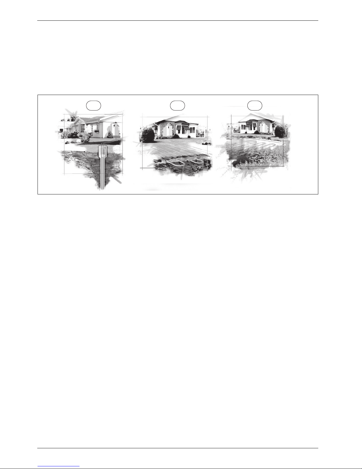
Greenline HE is a series of heat pumps that use stored
solar energy in order to provide water-based heating and
hot water.
Fig. 1 Stored solar energy
1 Bedrock heat
2 Ground heat
3 Lake water heat
C6 - C11 are heat pumps with integrated hot water
heaters.
E6 - E17 are heat pumps designed to be supplemented
with an external hot water heater.
Once the heat pump has been installed and started,
there are a number of points that should be checked
regularly. This may concern an alarm triggering or
performing basic maintenance actions. If the problem is
repeated, you should contact the dealer.
2.2 Heat pump function
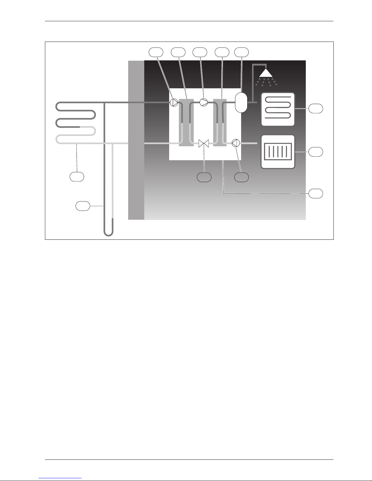
The heat pump consists of four main parts:
• Evaporator
Evaporates the refrigerant to gas and at the same time
transfers the heat from the collector to the refrigerant
circuit.
• Condenser
Condenses the gas to fluid again and transfers the
heat to the heating system.
• Expansion valve
Lowers the pressure of the refrigerant.
• Compressor
Increases the pressure of the refrigerant.
These four main parts are linked in three circuits. A
refrigerant circulates in the heat pump, which in some
parts of the circuit is in a liquid state and in other parts
in a gas state.
123
6 720 614 540-01.2I
Page 5
Use
6 720 643 415 (2010/03)
5
Fig. 2 Operating description
1 Heat transfer fluid pump
2 Evaporator
3 Compressor
4 Condenser
5 Water heater
6 Floor heating
7 Radiator
8 Heat pump
9 Heat carrier pump
10 Expansion valve
11 Borehole (bedrock heat)
12 Geothermal heating coil
• The collector circuit fluid, which is a mixture of water
and anti-freeze, circulates in the borehole/geothermal
heating coil in a plastic hose. The fluid collects stored
solar energy and with the help of the collector circuit
pump leads it into the heat pump and to the
evaporator. The temperature is then approximately
0°C.
• In the evaporator, the heat transfer fluid meets the
refrigerant. The refrigerant is then in a fluid state and
is at approximately -10 °C. When the refrigerant
meets the zero degree heat transfer fluid, it starts to
boil. A vapour is formed, which is then led into the
compressor. The temperature of the vapour is 0 °C.
• The pressure of the refrigerant increases in the
compressor and the temperature of the vapour rises
to approx. +100 °C. The hot gas is then forced into the
condenser.
• In the condenser, the heat is transferred to the
house’s heating system (radiators and floor heating)
and the hot water system. The vapour is cooled and
becomes fluid. The pressure in the refrigerant is still
high when it is led on to the expansion valve.
• The refrigerant pressure is lowered in the expansion
valve. At the same time, the temperature also drops to
approximately -10 °C. When the refrigerant passes
the evaporator it changes to vapour again.
• The heat transfer fluid is led out from the heat pump
to the borehole/geothermal heating coil to collect
new stored solar energy. The temperature of the fluid
is approx. -3 °C.
1 2 3 4
5
6
7
8
11
910
12
6 720 614 540-02.3I
Page 6

Energy metering
6 720 643 415 (2010/03)
6
3 Energy metering
Energy metering in the heat pump is an approximation
based on the sum of the nominal emitted output during
the relevant metering period. The calculation requires
for example that the heat pump is correctly installed,
and that the flow and Δ temperatures on the hot and
cold sides are adjusted as recommended. The value
should therefore be regarded as an estimate of the
actual emitted output. The margin of error in the
calculation is normally put at 5-10%
In addition, the energy output is affected by the outdoor
temperature, the settings for the thermostat and room
controls and heat pump usage. Ventilation, indoor
temperature and hot water demand can play a deciding
role.
Page 7

Control unit
6 720 643 415 (2010/03)
7
4 Control unit
The control unit controls and monitors the heating and
hot water production with the heat pump and additional
heat. The monitoring function shuts down the heat
pump in the event of operational disturbances so as to
prevent damage to critical parts of the pump.
4.1 Additional heat
The heat pump can be dimensioned to cover the peak
output of the house single-handedly and does not
normally need any additional heat then. Although in that
case there can be an additional heater installed solely
for emergency operation, when the heat pump is
stationary.
The heat pump can also be dimensioned to cover the
needs of the house to a somewhat lower degree and
then will need additional heat for the time of the year
when it is coldest. The additional heat also helps in the
event of emergency operation, extra hot water and hot
water peak.
The additional heat is provided through electric
additional heat.
The control unit activates automatically the additional
heat, if necessary.
4.2 Hot water production
Hot water is heated in the hot water heater and the
control unit gives priority to hot water before the heating
of heating water according to the settings that are made.
The hot water heater is fitted with a sensor that senses
the temperature of the hot water.
Page 8
Control panel
6 720 643 415 (2010/03)
8
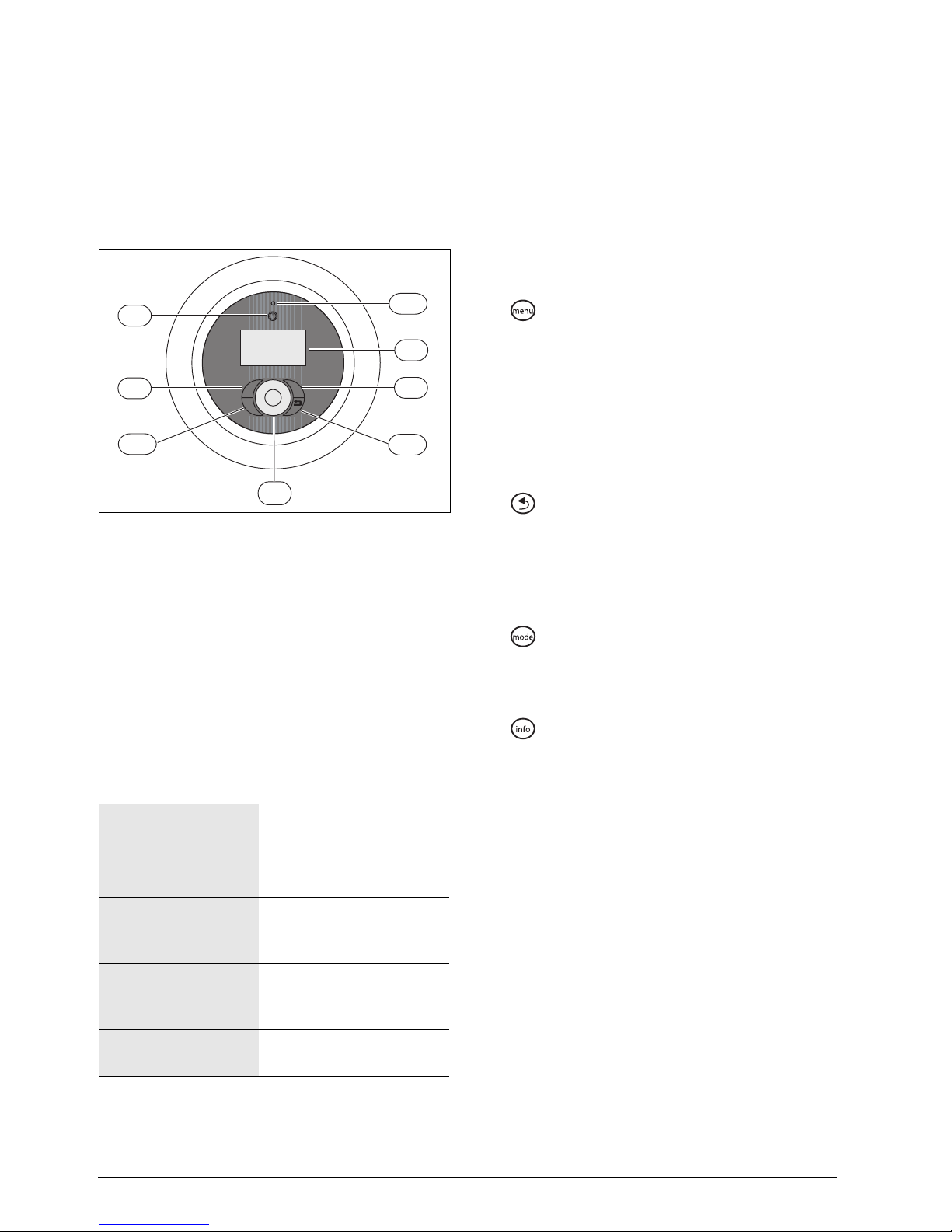
5 Control panel
Settings for the control of the heat pump are made with
the control unit's control panel, which also provides
information about current status.
5.1 Panel overview
Fig. 3 Control panel
1 On/Off button
2 Mode button
3 Info button
4 Menu dial
5 Status lamp
6 Return button
7 Menu button
8 Menu display
5.2 Power switch (ON/OFF)
Use the On/Off button to switch the heat pump on and
off.
5.3 Status lamp
5.4 Menu display
Use the menu display in order to:
• See information from the heat pump.
• See available menus.
• Change set values.
5.5 Menu button and menu dial
Use to get from Initial menu to the menus. Use the
menu dial in order to:
• Navigate the menus and get to the setting displays.
– Turn the dial to see more menus on the same level
or change a set value.
– Press the dial to change to a lower menu level or
save a change.
5.6 Return button
Use to:
• Go back to the previous menu level.
• Leave a setting display without changing the set
value.
5.7 Mode button
Use to change type of operation.
• Change type of operation.
5.8 Info button
Use to see information from the control unit about
operating mode, temperature, program version, etc.
The lamp lights green. The heat pump is running.
The lamp flashes red. There is an alarm which
has not been
acknowledged
The lamp lights red. The alarm has been
acknowledged but the
alarm cause remains
Lamp flashes slowly
green, menu window
not lit.
The heat pump is in standby mode
1)
.
1) Stand-by means that the heat pump is running but no
heating or hot water demand exists.
The lamp and menu
display not lit.
No voltage to control unit.
Tab. 2 Lamp functions
menu
mode
i
6 720 641 855-08.1I
5
6
2
8
1
7
4
3
Page 9

Menu overview
6 720 643 415 (2010/03)
9
6 Menu overview
Room temperature General (Summer/winter operation, Maximum operating time for heating
at hot water demand)
Circuit 1 Heating (Heating, Room sensor, Room temperature program)
Circuit 2, 3... (optional) (Heating, Room sensor, Room temperature
program)
Hot water Extra hot water (period, Stop temperature)
Hot water peak (Day of the week, Interval, time)
Hot water program
Hot water mode
Block heating during hot water demand
Maximum operating time for hot water at heating demand
Holiday Circuit 1 and Hot water
Circuit 2, 3... (optional)
Energy measurements Generated energy
Consumption electric additional heat
Timers Timers that are running are displayed, for example for Extra hot water
duration
External control External input 1, 2
External input circuit 2, 3... (optional)
General Set date
Set time
Summer/winter time
Display backlight intensity
Language
Alarms Information log
Delete information log
Alarm log
Delete alarm log
Alarm indication (Alarm buzzer signal, Alarm indication control unitand
Room sensor)
Access level
Return to factory settings
Tab. 3 Menu overview
Page 10
Menu navigation
6 720 643 415 (2010/03)
10
7 Menu navigation
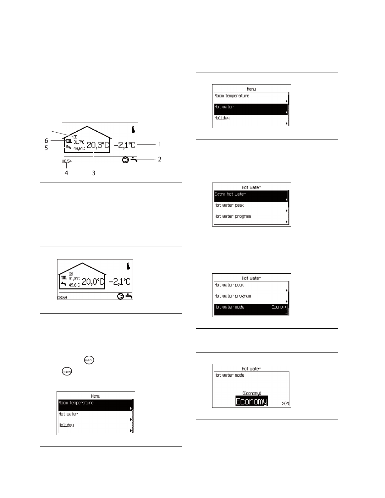
7.1 Initial menu
Initial menu shows different temperatures, time, as well
as current operating symbols. The window displays
information alternately Room temperature (if room
sensors exist) and Flow temperature for each circuit
installed.
Fig. 4 Initial menu
1 Outdoor temperature
2 Current operating symbols
3 The circuit room temperature
4 Current time
5 Hot water temperature
6 Circuit flow temperature
7 Circuit number
Fig. 5 Initial menu, circuit 2 is displayed
7.2 Finding desired function and changing
value
Menu overview (Æ Page 9) shows the main functions that
are reached with and the dial.
B Press .
Fig. 6
B Turn the dial to mark a desired menu bar.
Fig. 7
B Select the function by pressing the dial. The first
three menu functions under Hot water are displayed.
Fig. 8
B Turn the dial to see other menu lines.
Fig. 9
B Press the dial to select the function.
Fig. 10
6 720 614 789-12.1I
7
6 720 614 789-02.1I
6 720 643 415-01.1I
6 720 643 415-02.1I
6 720 643 415-03.1I
6 720 643 415-04.1I
6 720 643 415-05.1I
Page 11
Menu navigation
6 720 643 415 (2010/03)
11
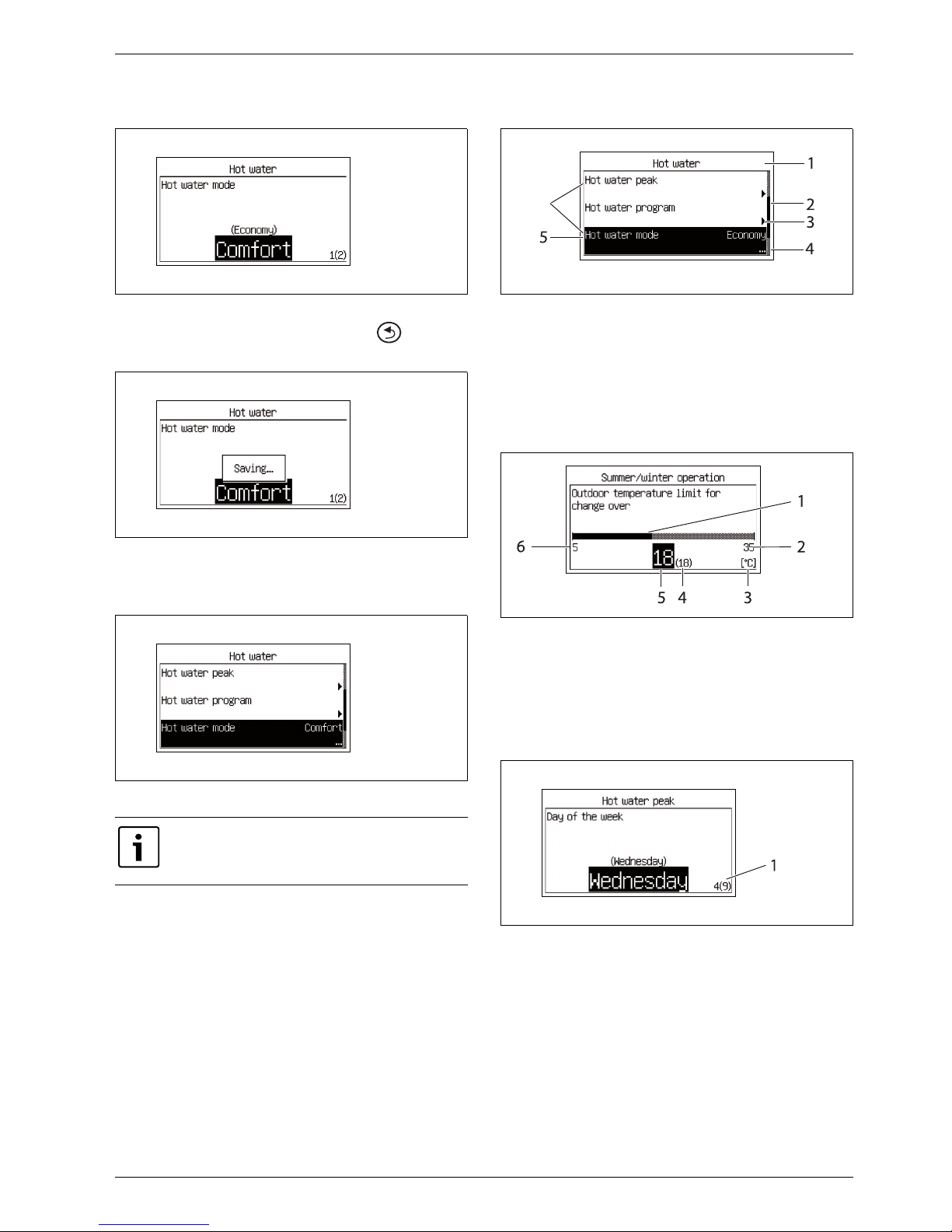
B Turn the menu dial to change the set value.
Fig. 11
B Press the dial to save the value or use to return
without changing.
Fig. 12
The control unit automatically returns to the menu
after the value has been saved.
Fig. 13
7.3 Help information in the menu display
Fig. 14 Help information 1
1 The menu level is Hot water
2 Drop-down list. The marked row shows your position among
the functions under Hot water.
3 The arrow shows that there is new menu on the next level.
4 The points show that the next level is a setting window.
5 The function is marked.
6 Three of the functions under Hot water.
Fig. 15 Help information 2
1 Graphic display of the value.
2 Highest possible value.
3 Unit.
4 Previous value.
5 New value. (Saved when the menu dial is pressed.)
6 Lowest possible value
Fig. 16 Help information 3
1 Option 4 out of 9 is displayed.
Economy and Comfort explained in more
detail in the chapter about hot water mode
(Æ Chapter 10.3).
6 720 643 415-06.1I
6 720 643 415-07.1I
6 720 643 415-08.1I
6 720 643 415-09.1I
6
6 720 643 415-10.1I
6 720 643 415-11.1I
Page 12

Information from the heat pump
6 720 643 415 (2010/03)
12
8 Information from the heat pump
The heat pump provides information about
temperatures, operating modes, possible alarms, etc.
8.1 Operating information
The Initial menu shows different temperatures and times
of day. Different operating symbols show the functions
for which there are needs or which are in operation.
Fig. 17
8.2 Info button
B Press in the Initial menu.
Detailed information about temperatures, operating
mode, etc., is displayed.
B Turn the dial to see all the information.
B Press to return to the initial menu.
B Press in a menu display.
The detailed information is displayed for as long as
is pressed.
B Release .
The menu display is displayed.
Fig. 18
8.3 Operating symbols
Symbols for different functions and components for
which there is a need or which are in operation are
displayed in the bottom right corner of the Initial menu.
Fig. 19 Operating symbols
1 Compressor
2 Alarm (compressor, additional heat)
3 Heating
4 Electric add. heat
5 Energy supply cut-off
6 Hot water
7 Extra hot water
8 Hot water peak
9 Pool (option)
10 Cooling (option)
11 Sun (option)
12 Screed drying
13 External controls
14 Program/Time control
15 Party mode
16 Holiday
17 Information log
6 720 614 789-01.1I
6 720 643 415-12.1I
1 2 3
4 5 6
7 8 9
10 11
6 720 641 883-15.1I
1514
16
13
12
17
Page 13

Heating, general
6 720 643 415 (2010/03)
13
9 Heating, general
9.1 Circuits for heating
• Circuit 1; the first circuit is included by default in the
control unit and is controlled by the installed flow
sensor, possibly in combination with an installed
room sensor.
• Circuit 2-4 (mixed); control of up to 3 additional
circuits is optional. Each circuit is then fitted with a
mixing valve module, circulation pump, flow sensor
and possible room sensors.
9.2 Control method for heating
• Outdoor sensor; a sensor is fitted on the outside wall
of the house. The sensor sends signals to the control
unit in the heat pump. Control with an outdoor sensor
means that the heat pump automatically regulates the
heating in the house depending on the outdoor
temperature. The customer determines the
temperature of the heating system in relation to the
outdoor temperature by setting the heat curve on the
control unit.
• Outdoor sensor and room sensors (one room sensor
per circuit is possible); Control with outdoor sensor
supplemented with room sensor(s) means that one
(or several) sensors are mounted in a central location
inside the house. It is connected to the heat pump
and provides the control unit with information about
the current room temperature. The signal affects the
flow temperature. For example, it falls when the room
sensor indicates a higher temperature than the one
set. Room sensors are used when factors other than
the outdoor temperature influence the indoor
temperature of the house. For example, this can be
when a stove or fan-assisted radiator is used in the
house, or if the house is sensitive to the wind or
exposed to direct sunlight.
9.3 Clock setting of heating
• Program control; The control unit offers a possibility
to define two individual programs for time control of
the heating.
• Holiday; the control unit has a program for holiday
mode, which means that during the selected period
the room temperature changes to a lower or higher
level. The program also allows switching off hot water
production.
• External control; the control unit can make settings
for external control, which means that the
preselected function is performed when the control
unit senses an input signal.
9.4 Operating modes
• With electrical additional heat; the heat pump is
dimensioned less than the house peak heating load
and electrical additional heat is permitted to cut in at
the same time as the heat pump to meet the demand,
when the heat pump cannot meet it itself. Alarm
mode, Extra hot water and Hot water peak, and if the
heat pump is off at low outdoor temperatures, the
addition is also activated.
Circuits 2 through 4 cannot have a higher
flow temperature than circuit 1. This means
that underfloor heating on circuit 1 cannot
be combined with radiators on another
circuit. Room temperature reduction for
circuit 1 can affect other circuits in some
cases.
The maximum number of circuits is reduced
by one circuit for each XB2 based accessory,
such as IVT PKS 1000.
It is only the room where the room sensor is
located that can influence regulation of the
temperature for the relevant heating circuit.
Page 14

Settings Customer level
6 720 643 415 (2010/03)
14
10 Settings Customer level
10.1 Mode button functions
By pressing , the following functions can be used
directly:
• Party
• Holiday
• Disable cooling
• Extra hot water duration
> Party
Party mode means that a running room program is
aborted during the set time in order to avoid a
temperature drop.
>> Number of hours
B Select the number of hours that party mode should be
active for.
The function starts immediately on all activated
circuits.
>> Circuit 1
>> Circuit x
B Select Yes to enable party mode.
Party mode can be enabled for each installed circuit.
The menu is displayed only if more than one circuit is
installed.
>> Deactivate party mode
B Select Yes to disable party mode on all activated
circuits.
The heat pump returns to program mode.
The menu is displayed only if party mode is active.
> Holiday
The same functions are included here as in the Holiday
menu (Æ Chapter 10.4).
> Disable cooling
The menu is displayed only if the cooling function is
installed and affects all circuits with cooling.
> Extra hot water duration
B For a description of setting Extra hot water
(ÆChapter 10.3).
10.2 Room temperature
Press the button in the standard display to open the
main menu. Select Room temperature to adjust the
heating.
The following options are available under Room
temperature:
• General
• Circuit 1 Heating
• Circuit 2, 3...
> General
>> Summer/winter time
>>> Winter operation
Factory setting 0h
Lowest value 0h
Highest value 99h
Tab. 4 Party duration
Factory setting No
Alternative No/Yes
Tab. 5 Enable party mode
Factory setting No
Alternative No/Yes
Tab. 6 Deactivate party mode
Factory setting No
Alternative No/Yes
Tab. 7 Disable cooling
It takes a long time before the cooling mode
manages to affect the temperature in the
house, therefore wait at least one day after
disabling/enabling before making any
additional adjustments.
Factory setting 0h
Lowest value 0h
Highest value 48h
Tab. 8 Extra hot water duration
After a period with blocked hot water
production, e.g., holiday, it is recommended
to enable the extra hot water function so as
to eliminate bacteria and quickly reach the
correct hot water temperature.
The following applies to Circuit 2,
3...requires the accessory IVT Mixing valve
module 1000
Page 15

Settings Customer level
6 720 643 415 (2010/03)
15
If On is selected, the heat pump is constantly in winter
operation and heat and hot water are always produced.
Off signifies constant summer operation; only hot water
is produced. Automatic signifies change-over at the set
outdoor temperature.
>>> Outdoor temperature limit for change over
The menu is displayed only if Automatic has been
selected in Winter operation.
>> Maximum operating time for heating at hot water
demand
The menu is not displayed if Block heating during hot
water demandbe set to Yes(Æ Chapter 10.3).
> Circuit 1 Heating
>> Heat curve
The heat curve constitutes the basis for the control
unit's control of the temperature on the heating water to
the circuit and indicates how high it needs to be in
relation to the outdoor temperature. The control unit
increases the temperature of the heating water when the
outdoor temperature drops. The temperature of the
heating water out to the circuit, i.e. the flow temperature
is measured by sensor T1 for circuit 1 (full name E11.T1)
and sensor T1 for circuit 2 (full name E12.T1).
Each circuit is controlled by its own heat curve. The
installer sets the type of heating for each circuit, that is
Radiator or Underfloor. The curve for Underfloor has
lower values because the floors do not tolerate such
high temperatures.
Fig. 20 Radiator
The images display the factory setting curve for radiator
circuit. At -2.5 °C the flow set point is 37.4 °C.
Fig. 21 Underfloor
The images display the factory setting curve for
underfloor circuit. At -2.5 °C the flow set point is
27.2 °C.
Heat curve set for each circuit. If the room temperature
is perceived to be too high or too low in the circuit, it is
preferable to adjust the curve.
The curve can be changed in different ways. The slope of
the curve can be changed by offsetting the flow line
temperature upwards or downwards in the left-hand
(the value at outdoor temperature 20 °C, factory value
22.0 °C) as well as right-hand points (the value at
outdoor temperature -35 °C, factory setting 60.0 °C). In
addition, the curve can be affected by every 5th outdoor
Factory setting Automatic
Alternative On/Automatic/Off
Tab. 9 Summer/winter operation
Factory setting 18 °C
Lowest value 5 °C
Highest value 35 °C
Tab. 10 Change over temperature
In the event of alternation between winter
and summer operation and vice versa, there
is a certain delay aimed at preventing
constant starting and stopping of the
compressor when the outdoor temperature
oscillates around the temperature limit.
F value 20min
Lowest value 0min
Highest value 120min
Tab. 11 Operating time heating
6 720 614 789-15.3I
T
1(˚C)
T2(˚C)
20 15 10 5 0 -5 -10 -15 -20 -25 -30 -35
80
70
60
50
40
30
20
10
6 720 614 789-16.3I
T
1(˚C)
T2(˚C)
20 15 10 5 0 -5 -10 -15 -20 -25 -30 -35
80
70
60
50
40
30
20
10
Page 16

Settings Customer level
6 720 643 415 (2010/03)
16
temperature degree.
The value at 0 °C is displayed above the curve's left-hand
part, factory value 35.7 °C.
Fig. 22 Setting window Heat curve (radiator)
Change the left point:
B Press the menu dial when the square is marked.
The value is marked.
Fig. 23
B Turn the menu dial to change the value. Press the dial
to save or use to return without saving.
In the window, the square is marked again and any
changed values are displayed after the square. In
addition, the curve is updated according to the new
value.
Change the right point:
B Turn the menu dial when the square is marked. The
upper square is changed to outdoor temperature with
the corresponding curve value after the colon. The
circle marks the relevant curve position.
B Continue to turn the dial until it shows a square
before the colon.
B Press the dial to mark the value.
Fig. 24
B Turn the menu dial to change the value. Press the dial
to save or use to return without saving.
In the window, the square is marked again and any
changed values are displayed after the square. In
addition, the curve is updated according to the new
value.
Change a specific value, for example the value at an
outdoor temperature of 0 °C:
B Turn the menu dial when the square is marked until
0°C is marked (Æ Image 25).
B Press the dial to mark the value.
Fig. 25
B Turn the menu dial to change the value.
Fig. 26
B Press the dial to save or use to return without
saving.
B Use to leave the curve setting window and return
to the menu.
6 720 614 789-18.3I
6 720 614 789-19.3I
6 720 614 789-23.3I
Recommendations:
B Increase the value of the right point if it
feels too cold at low outdoor
temperatures.
B Increase the value of curve at 0 °C if it
feels a little cold at outdoor temperatures
around 0.
B Increase or decrease the value of the
curve equally at the right and left points
to fine adjust the heat (the curve is
parallel offset).
6 720 614 789-21.3I
6 720 614 789-22.3I
Page 17

Settings Customer level
6 720 643 415 (2010/03)
17
>> Room sensor
>>> Room temperature influence
B Set how much a 1 K ( °C) difference in room
temperature should influence the set point value for
the flow temperature.
Example: at a 2 K ( °C) deviation from the set room
temperature, the set point value for the flow
temperature is changed by 6 K ( °C) (2 K deviation *
factor 3 = 6 K).
>>> Knob's operating range
B Set how many degrees the turn of the knob of the
room sensor should represent between + and – .
6K means that a full turn to + gives approx. +3K and a
full turn to – gives approx. -3K.
The room sensor measures the temperature in the room
where it is located. The value is compared with the set
desired room temperature under the Room temperature
program.
The influence of the room sensor is described in (Æ
Chapter 9.2).
>> Room temperature program
B Choose if the circuit should be controlled with a
program or not.
Optimised operation
This means that the control unit is only controlled by the
flow set point value (Æ Chapter 10.2.1), without
programmed changes during the day. Optimised
operation provides the best comfort and energy savings
in the vast majority of cases.
Program 1 and 2
These selections provide an opportunity to define own
programs for time control by adjusting the start and stop
times, as well as a normal and an exception temperature.
To set the desired time of day:
B Select Program 1 or Program 2.
B Go to menu View/edit active program.
B Select day by turning the menu dial.
Fig. 27
B Press the menu dial to mark the value to be changed.
Fig. 28
B Turn the menu dial until the desired setting has been
selected.
B Then press the menu dial.
B Turn the menu dial to be able to set additional values
in the same way as above.
B Go back one step with .
B Select Saving alternative:
– Return without saving
– Program 1
– Program 2
The set changes are saved as a selected program or
not at all.
B To adjust the normal temperature, proceed to menu
Room temperature normal.
B To adjust the exceptional temperature, proceed to
menu Room temperature exception.
Factory setting 3.0
Lowest value 0.0
Highest value 10.0
Tab. 12 Room temperature influence
Factory setting 6K
Lowest value 0K
Highest value 6K
Tab. 13 Operating range, room sensor knob
F value Optimised operation
Alternative • Optimised operation
• Program 1
• Program 2
Tab. 14 Program selection, circuit 1
Program Day Start Stop
Program 1, 2 Mon - Sun 5:30 22:00
Tab. 15 Program 1 and 2
6 720 643 415-13.1I
6 720 643 415-14.1I
Page 18

Settings Customer level
6 720 643 415 (2010/03)
18
Room temperature program when there are room
sensors:
>> Room temperature program
>>> Active program
If a program is selected, the following (if the menu
button is turned) is displayed:
>>> View/edit active program
>>> Room temperature normal
B Set the desired set point for the room temperature.
>>> Room temperature exception
B Set the temperature that should apply as exceptional
temperature in the program.
The menu is displayed only if Program 1 or Program
2 has been selected.
>>> Copy to all heating circuits
B Select Yes to have the same control for all installed
circuits.
The menu is displayed only under Circuit 1.
Room temperature program when there is no room
sensor:
>> Room temperature program
>>> Active program
>>> View/edit active program
The same as when there is a room sensor, see above.
>>> Room temperature normal
B Set the measured value in the room.
The indicated value is used by temperature programs
to calculate the difference between normal and
exceptional temperature.
>>> Temperature increase/decrease
B Use this function to adjust the room temperature so
that the normal room temperature (see the previous
menu) becomes the desired temperature.
B Use this function to simply increase or decrease the
heat when there are no room sensors.
– – gives approx. 1 °C lower room temperature.
– gives approx. 0.5 °C lower room temperature.
+ gives approx. 0.5 °C higher room temperature.
++ gives approx. 1 °C higher room temperature.
>>> Room temperature influence
Setting is carried out in the same way as in the menu
Room sensor
(Æ Chapter 10.2). The setting is used in the
temperature program to calculate how the flow line
temperature is affected when exceptional temperature
should apply.
>>> Room temperature exception
The same as when there is a room sensor, see above.
>>> Copy to all heating circuits
The same as when there is a room sensor, see above.
Factory setting 20.0 °C
Lowest value 10.0 °C
Highest value 35.0 °C
Tab. 16 Room temperature, normal
Factory setting 17.0 °C
Lowest value 10.0 °C
Highest value 30.0 °C
Tab. 17 Room temperature, exception
Factory setting No
Alternative No/Yes
Tab. 18 All circuits
Factory setting 20.0 °C
Lowest value 10.0 °C
Highest value 35.0 °C
Tab. 19 Room temperature, normal
Factory setting =
Alternative – – , – , =, +, ++
Tab. 20 Room temperature increase/decrease
It always takes some time for a change of a
heating setting, e.g. an increase or decrease
in room temperature, to apply. The same
applies in the event of a quick change of the
outdoor temperature. This is why you
should always wait for at least 24 hours
before making a new change.
Page 19

Settings Customer level
6 720 643 415 (2010/03)
19
> Circuit 2, 3...(optional)
Circuit 2, 3... has the same settings options as Circuit 1,
(Æ Chapter 10.2).
10.2.1 Set point value
The heating circuit's set point value is the temperature
of the flow that the heat pump attempts to maintain.
Sometimes, the measured actual value fluctuates a bit
upward and downward depending on changes in the
outdoor temperature or a large hot water demand.
The set point value is normally based on:
• Current curve value (the flow temperature at the
current outdoor temperature according to the
applicable heat curve).
• Current curve influence through:
– Room sensor
– Holiday
– Active program
– External control
Set point value calculation
The set point value for the heating circuit is the current
curve value adjusted with active curve influence, if any
such exists.
Priority order for curve influence is:
• External control
• Active program
• Holiday
• Room sensor
Only one of these can be active. How big the influence
should be and when to exercise it is set in the respective
function.
Fixed set point value
A fixed set point value (not curve-based) applies in the
event of:
• External set point value. The set point value is
determined according to input signal 0-10V where 1V
is 10 °C and 10V is 80 °C (0V triggers an alarm).
Set point value limitation
The calculated set point value is always checked against
the permitted temperature limits.
The applicable set point value T1 for Circuit 1 and the
measured actual value for T1 are used to activate and
deactivate the heat demand.
The following applies to Circuit 2, 3...: When the actual
value for the mixed circuit's T1 is low in relation to the
set point value, more heating water is shunted into the
circuit so as to maintain the set point value.
If the flow line temperature has been below the set point
value for a certain period of time, there is heat demand
and the compressor produces heat before there is a too
significant temperature reduction indoors. This happens
until the flow line temperature is a couple of degrees
higher than the set point value. (Or because Maximum
operating time for heating at hot water demand has
passed.)
Heating demand is not active during summer operation.
10.3 Hot water
Under Hot water, there are functions to:
• Request Extra hot water
• State when Hot water peak is to be carried out to
eliminate the bacteria
• Set any Hot water program
• Select operating mode
• Block heating needs during hot water mode
• Limit hot water mode at heat demand
> Extra hot water
Additional amount of hot water is produced by
temporarily increasing the temperature of the hot water
during the set number of hours to the indicated stop
temperature.
>> Extra hot water duration
B Set the duration of extra hot water production.
The following applies to Circuit 2,
3...requires the accessory IVT Mixing valve
module 1000
The set point value specified by the
customer/installer is most often the room
temperature, which is recalculated by the
control unit into a corresponding flow
temperature set point value. Under normal
conditions, 1 K ( °C) in room temperature
corresponds to approx. 3 K ( °C) in flow
temperature.
Factory setting 0h
Lowest value 0h
Highest value 48h
Tab. 21 Extra hot water duration
Page 20

Settings Customer level
6 720 643 415 (2010/03)
20
>> Extra hot water stop temperature
B Set the stop temperature for extra hot water.
The heat pump starts the function directly and uses first
the compressor and then the additional heat source for
the temperature increase. When the respective number
of hours have passed, the heat pump returns to normal
hot water mode.
> Hot water peak
Hot water peak means a temporary increase in the hot
water temperature to approx. 65 °C for thermal
elimination of bacteria.
For the hot water temperature increase, the compressor
is used first; the additional heat source then continues
alone.
>> Day of the week
B Set the day on which the hot water peak should take
place. None means that the function is disabled. All
means that a hot water peak takes place every day.
If hot water peak is deactivated comfort mode must
be selected in the menu Hot water mode.
>> Interval in weeks
B Set how often a hot water peak should take place.
– 1 means a hot water peak every week.
– 2 means that a hot water peak takes place in all
even weeks of the year, i.e. in week 2, 4, 6, etc.
– 3 means week 3, 6, 9, etc.
– 4 means week 4, 8, 12, etc.
>> Start time
B Set the time of the hot water peak.
> Hot water program
Program 1 and Program 2 enables you to block hot
water production during the set time.
>> Active program
>> View/edit active program
The menu is displayed only if Program 1 or Program 2
has been selected. Programs are changed in the same
way as for Room temperature program
(ÆChapter 10.2).
> Hot water mode
B Select hot water mode.
Economy means that the hot water is permitted to
cool slightly before hot water production starts
compared to Comfort. Heating stops at a slightly
lower temperature.
B Change to Comfort if more or hotter hot water is
desired.
This setting must be used if electric add. heat is
missing or if the hot water circulation is used, when
the temperature in the hot water circulation is
otherwise too low.
The factory settings for on and off temperature are
approx. 8 K lower in Economy mode compared to
Factory setting 65 °C
Lowest value 50 °C
Highest value 65 °C
Tab. 22 Hot water temperature
DANGER: Risk of burn injuries.
B Use a mixing valve when the hot water
temperature exceeds 60 °C.
Factory setting Wednesday
Area None, Day, All
Tab. 23 Weekday
Factory setting 1
Lowest value 1
Highest value 4
Tab. 24 Week interval
Factory setting 3:00
Lowest value 0:00
Highest value 23:00
Tab. 25 Start time
WARNING: Risk of burn injuries.
At hot water temperatures greater than
60 °C, there is a risk of burn injuries.
B Exercise caution when tapping hot water
immediately after a hot water peak.
Factory setting Always hot water
Alternative • Always hot water
• Program 1
• Program 2
Tab. 26 Hot water program
F value Economy
Alternative Economy/Comfort
Tab. 27 Hot water mode
Page 21

Settings Customer level
6 720 643 415 (2010/03)
21
Comfort mode. These values can be adjusted by the
installer.
> Block heating during hot water demand
B Select Yes if the hot water demand must always be
satisfied before the heat demand.
B Select No if hot water production should be
interrupted after a certain time in event of a heat
demand.
B In No also set the duration that hot water production
may occur for during the heat demand.
> Maximum operating time for hot water at heating
demand
10.4 Holiday
During holidays (absence), the heating can, for example,
be kept at a lower or higher level and hot water
production can be switched off. Start and Stop date,
Room temperature and Block hot water production is only
displayed if the holiday function is activated.
> Circuit 1 and hot water
>> Activate holiday function
>> Start date
>> Stop date
B Set start and stop date for the desired period. Format
yyyy-mm-dd.
The period starts and ends at 00:00. Both the start
and end date are included in the period.
B Terminate the period prematurely by indicating No in
the menu Activate holiday function.
>> Room temperature
B Set the room temperature that should apply to the
circuit during the period.
>> Copy to all heating circuits
>> Block hot water production
> Circuit 2, 3...
>> Activate holiday function
>> Start date
>> Stop date
>> Room temperature
B Set the values in the same way as for Circuit 1 and
hot water.
10.5 Energy measurements
> Generated energy
This displays Generated energy in kWh divided into
Heating and Hot water.
> Consumption electric additional heat
This displays Consumption electric additional heat in
kWh divided into Heating and Hot water.
F value No
Alternative Yes/No
Tab. 28 Block the heat
F value 30 min
Lowest value 5 min
Highest value 60 min
Tab. 29 Operating time hot water
Factory setting No
Alternative No/Yes
Tab. 30 Holiday function
Factory setting 17 °C
Lowest value 10 °C
Highest value 35 °C
Tab. 31 Room temperature, holiday
Factory setting No
Alternative Yes/No
Tab. 32 Copy circuits
Factory setting No
Alternative Yes/No
Tab. 33 Block hot water
Page 22

Settings Customer level
6 720 643 415 (2010/03)
22
10.6 Timers
Timers are used by the control unit to count down the
different time dependent functions such as Extra hot
water duration. At customer level the following timers
can be observed (only timers that are counting are
displayed):
10.7 External controls
When an external input is connected, the control unit
performs functions which are set to Yes or is separated
from 0 (Room temperature). When the external input is
no longer connected, the control unit returns to normal
mode. Only installed functions are displayed.
> External input 1, 2
>> Block compressor
>> Block heating
>> Room temperature
>> Block hot water production
> External input circuit 2, 3...(optional)
>> Block heating
>> Room temperature
Room temperature:
B Set the room temperature that should apply in the
event of enabled external control.
B Value > 0 °C enables the function.
Other functions:
10.8 General
Among other things, settings for date and time are
available here.
> Set date
> Set time
B Check and change, if necessary, date and time. These
are used by the control unit to manage the different
clock settings, e.g., holiday and room temperature
program.
> Summer/winter time
B Select if there should be automatic change over
between summer and winter time or not (times
according to EU standard).
> Display backlight intensity
B If necessary, change the background light of the
control panel.
> Language
B Change language, if desired.
Timer F value
Extra hot water 0h
Alarm mode delay 1h
Party 0h
Operating time for heating at hot water
demand
20min
Hot water, operating time at heating
demand
30min
Heat pump x timers
> Compressor start delay 10min
Additional heat timers
> Additional heat start delay 60min
> Delay mixing valve control after
additional heat start
20min
Tab. 34 Timers
Factory setting No (0.0 °C)
Lowest value 10.0 °C
Highest value 35.0 °C
Tab. 35 Room temperature
F value No
Alternative Yes/No
Tab. 36 Functions
Factory setting
Format yyyy-mm-dd
Tab. 37 Date
Factory setting
Format hh:mm:ss
Tab. 38 Time
Factory setting Automatic
Alternative Manual/Automatic
Tab. 39 Summer/winter time.
Factory setting 100%
Lowest value 20%
Highest value 100%
Tab. 40 Display backlight intensity
Page 23

Settings Customer level
6 720 643 415 (2010/03)
23
10.9 Alarm
The different alarms that can occur are described in
(ÆChapter 11).
Under Alarms there is:
• Information log
• Delete information log
• Alarm log
• Delete alarm log
• Alarm indication
> Information log
The information log displays information from the heat
pump. The control panel output mode displays the
symbol for information log when the active information
is available.
> Delete information log
The information log is deleted here.
> Alarm log
The alarm log shows the alarms and warnings that have
occurred. Alarm category (Æ Chapter 11.5) is displayed
in the top left corner of the display. If the alarm is active,
the alarm symbol (ÆChapter 8.3) is displayed both in
the alarm log and the initial menu of the control panel.
> Delete alarm log
The alarm log is deleted here.
> Alarm indication
Under Alarm indication settings for alarm buzzer and
status lamp are made here.
>> Alarm buzzer signal
>>> Interval
B Set the length of the alarm interval.
The alarm buzzer sounds for one second and is silent
during the rest of the interval. The setting applies to
all alarm buzzers.
>>> Blocking time
B Set the times between which alarms buzzers should
not be allowed to produce an acoustic signal.
>> Alarm indication control unit
>>> Block alarm buzzer
The setting applies only to the control unit's alarm
buzzer.
>> Alarm indication room sensor
>>> Block alarm buzzer
The setting applies only to circuit 1.
The setting applies to Circuit 1 and to a CANbusconnected room sensor.
The setting applies to all room sensors.
10.10 Access level
Access level is Customer as standard: This level gives
you access to all functions that the user requires. The
installer also has access to the additional functions
required at installation.
10.11 Return to factory settings
B Select Return to factory settings and Yes to reset all
customer settings to the factory settings. Settings
made by the installer are not affected.
Factory setting 2s
Lowest value 2s
Highest value 3600s (60min)
Tab. 41 Interval
Factory setting Off
Start time 0:00 - 23:45
Stop time 0:00 - 23:45
Tab. 42 Blocking time
Factory setting No
Alternative No/Yes
Tab. 43 Block alarm buzzer
Factory setting Yes
Alternative No/Yes
Tab. 44 Block alarm buzzer
Factory setting Yes
Alternative No/Yes
Tab. 45 Block status lamp
Factory setting No
Alternative Yes/No
Tab. 46 Return to factory settings
Page 24

Alarm
6 720 643 415 (2010/03)
24
11 Alarm
11.1 Control unit and room sensor alarm
lamp
The status lamp on the control unit is used to show ON/
OFF status for the heat pump but also to show possible
alarms. The status lamp is therefore also called alarm
lamp. If there are room sensors, it/they provides the
same information as the lamp on the heat pump.
In the event of an alarm the alarm lamp flashes red
(control unit) until the warning cause has disappeared.
The alarm lamp is not used for warning alarms.
The room sensor alarm lamp can be blocked.
The alarm lamp of the CANbus sensor shows the same
information as the alarm lamp of the control unit.
Other room sensors flash with low-frequency red light in
the event of alarms; the lamp is otherwise off.
11.2 Alarm buzzer at alarm
When there is an alarm, the alarm buzzer on the heat
pump and the CANbus-connected room sensor sounds
for a second per set alarm interval. The alarm buzzer can
be blocked for a certain part of the day or completely.
In the event of a warning alarm, the alarm buzzer does
not sound.
11.3 Acknowledgement of alarms
Acknowledgement means that you have to press to
make the alarm window disappear. What happens after
acknowledgement is described in the respective alarm
description.
In most cases, warnings do not have to be
acknowledged. The alarm window disappears by itself
once the warning cause has disappeared. It is, however,
possible to acknowledge the warning.
11.4 Alarm timer, alarm mode
In the event of an alarm that stops the compressor the
control unit starts a timer at 1h. If the fault does not
recur additional heat may start when the timer has
counted down.
Behaviour Function
The lamp lights
green
continuously.
The heat pump is running.
The lamp
flashes red
There is an alarm which has not
been acknowledged
The lamp lights
red
continuously.
The alarm has been
acknowledged but the alarm
cause remains
Lamp flashes
green slowly
The heat pump is in stand-by
mode
1)
1) Stand-by means that the heat pump is running but no
heating or hot water demand exists.
Tab. 47 Alarm lamp control unit
Page 25

Alarm
6 720 643 415 (2010/03)
25
11.5 Alarm categories
The alarms are divided into different categories depending on the type and seriousness of the fault. Alarm category is
displayed in the alarm window and alarm log.
Categories A-H are alarms, categories I-J are warnings/information, categories K-M are warnings, category Z is
information.
In Temporary stop of compressor. The information may recur
a number of times during a certain time period; if there are
more during the period, a category A alarm is sounded.
J Temporary stop of compressor. The information may recur
a number of times during a certain time period; if there are
more during the period, a category A alarm is sounded.
M Used for board connection problems.
11.6 Alarm window
When an alarm/warning occurs, the display shows
information about what has happened. At the same time,
information is saved in the alarm log. The alarm symbol
is displayed in the initial menu of the control panel
(Æ Chapter 8.3).
Example of an alarm:
Fig. 29
Meaning A B C D E F G h In J K L M Z
Stops the compressor X XX XX X X
Stops additional heat XX X
Alarm lamp, alarm buzzer is
activated
X XX XXXXX
Alarm delay 5s 3s 15 min 1 min 5s 1s 1s 1s 5s 5s 2s 5s 0s 0s
Requires acknowledgement to
restart
X XX X X
Can be restarted before
acknowledgement
X X XXXX X
Menu display must be
acknowledged
X XX XXXXX XX
Placed in the information log X X X
Tab. 48 Alarm categories
6 720 643 415-15.1I
Page 26

Alarm
6 720 643 415 (2010/03)
26
11.7 Alarm functions
The different alarms that can occur are presented here,
the alarm text is indicated in the heading.
Most alarm texts contain a designation of the part of the
heat pump that has caused the alarm. Always indicate
the whole alarm information when you are in contact
with the service/dealer.
E21 refers to top heat pump 1, E22 refers to bottom heat
pump 2.
E11 refers to circuit 1, E12 circuit 2, E13 circuit, 3, etc.
Txx refers to different temperature sensors.
11.7.1 High hot gas temperature E2x.T6
Function: Compressor stops. Activated when the
temperature from the compressor becomes too high.
The alarm can occur in individual cases under extreme
service conditions.
Alarm timer starts: Yes.
Reset condition: The hot gas temperature drops to the
permitted temperature.
Category: A.
Alarm lamp/buzzer: Yes.
Restart: Acknowledgement is required.
B Contact the dealer if the alarm remains active for
more than three hours or recurs often.
11.7.2 Tripped low pressure switch E2x.RLP
Function: Compressor stops. Activated when the
pressure in the refrigerant circuit of the heat pump
becomes too low.
Alarm timer starts: Yes.
Reset condition: The pressure goes back to the
permitted level.
Category: A.
Alarm lamp/buzzer: Yes.
Restart: Acknowledgement is required.
B Check that the air ways to and from the heat pump are
not obstructed.
B Contact the dealer if the alarm remains after
acknowledgement.
11.7.3 Tripped high pressure switch E2x.RHP
Function: Compressor stops. Activated when the
pressure in the refrigerant circuit becomes too high.
Alarm timer starts: Yes.
Reset condition: The pressure goes back to the
permitted level.
Category: A.
Alarm lamp/buzzer: Yes.
Restart: Acknowledgement is required.
B Contact the dealer if the alarm remains after
acknowledgement.
11.7.4 Low pressure collector circuit
Function: Compressor stops. Activated when the
pressure in the collector circuit becomes too low.
Alarm timer starts: Yes.
Reset conditon: The pressure goes back to the
permitted level.
Category: A.
Alarm lamp/buzzer: Yes.
Restart: Acknowledgement is required.
B Contact the dealer if the alarm remains after
acknowledgement.
11.7.5 Low temperature collector circuit in E2x.T10
Function: Alarm is given if the collector circuit
temperature is too low and if warning of this has been
given several times.
Alarm timer starts:
Yes.
Reset condition: The collector circuit temperature
exceeds the lowest permitted temperature.
Category: A.
Alarm lamp/buzzer: Yes.
Restart: Acknowledgement is required.
B Contact the dealer if the alarm remains after
acknowledgement.
Page 27

Alarm
6 720 643 415 (2010/03)
27
11.7.6 Low temperature collector circuit out E2x.T11
Function: Alarm is given if the collector circuit
temperature is too low and if warning of this has been
given several times.
Alarm timer starts: Yes.
Reset condition: The temperature of the refrigerant
exceeds the lowest permitted temperature.
Category: A.
Alarm lamp/buzzer: Yes.
Restart: Acknowledgement is required.
B Contact the dealer if the alarm remains after
acknowledgement.
11.7.7 Motor cut-out 1 E2x.F11, Compressor
Function: Activated when the compressor's motor cut-
out has tripped because of high current or lost current
phase resulting in undue strain on the compressor.
Alarm timer starts: Yes.
Reset condition: Motor cut-out reset.
Category: B.
Alarm lamp/buzzer: Yes.
Restart: Acknowledgement is required.
B Check the heating system fuses, and main fuses.
B Contact the dealer if the alarm remains after
acknowledgement.
11.7.8 Motor cut-out 2 E2x.F12, Collector circuit
pump
Function: Compressor stops. Activated when the
collector circuit pump motor cut-out has tripped. The
heat transfer fluid (coll.) pump stops and the heat pump
also stops to protect the other components.
Alarm timer starts: Yes.
Reset condition: Motor cut-out reset.
Category: B.
Alarm lamp/buzzer: Yes.
Restart: Acknowledgement is required.
B Check heating system fuses.
B Contact the dealer if the alarm remains after
acknowledgement.
11.7.9 Phase error E2x.B1
Function: Compressor stops. Activated when one of the
phases in the voltage supply is missing or when there is
a phase sequence error. A voltage difference > 15%
between the phases also results in an alarm.
Alarm timer starts: Yes.
Reset condition: The error has been remedied and the
phase guard is under voltage.
In the event of a voltage difference: The difference
between phases has been reduced to < 15 %.
Category: E.
Alarm lamp/buzzer: Yes.
Restart: Acknowledgement is required.
B Check the heating system fuses, and main fuses.
B Contact the dealer if the alarm remains after
acknowledgement.
11.7.10 Failure on sensor E2x.T6 hot gas
Function: The compressor stops because the hot gas
cut-out cannot be guaranteed. Activated when the
sensor's value indicates a temperature lower than
-50 °C.
Alarm timer starts: Yes.
Reset condition: The value of the sensor indicates >
-50 °C.
Category:
E.
Alarm lamp/buzzer: Yes.
Restart: Automatic once the alarm cause has
disappeared.
B Contact the dealer if the alarm remains active for
more than three hours or recurs often.
11.7.11 Short circuit on sensor E2x.T6 hot gas
Function: The compressor stops because the hot gas
cut-out cannot be guaranteed. Activated when the
sensor's resistance value indicates a temperature higher
than 150 °C.
Alarm timer starts: Yes.
Reset condition: The value of the sensor indicates <
150 °C.
Category: E.
Alarm lamp/buzzer: Yes.
Restart: Automatic once the alarm cause has
disappeared.
B Contact the dealer if the alarm remains active for
more than three hours or recurs often.
Page 28

Alarm
6 720 643 415 (2010/03)
28
11.7.12 High flow temperature E1x.T1
Function: Compressor stops. Activated when the
temperature in the heating circuit becomes too high in
relation to the settings that are made.
Alarm timer starts: Yes.
Reset condition: The sensor's value falls below the
temperature for beginning of the heating demand.
Category: E.
Alarm lamp/buzzer: Yes.
Restart: Automatic once the alarm cause has
disappeared.
B Lower the heating on the circuit.
B Check that the thermostat valves are open.
B Contact the dealer if the alarm recurs often.
11.7.13 Faulty electric heater E21.E2
Function: The electric heater is turned off. Activated by
triggered overheat protection on the electric add. heat,
high flow temperature or too high temperature in the
electric add. heat.
Reset condition: Overheat protection reset or the
temperature has fallen.
Category: F.
Alarm lamp/buzzer: Yes.
Restart: Acknowledgement is required.
B Reset the overheat protection if it has tripped.
B Contact the dealer if the alarm remains after
acknowledgement.
11.7.14 Overheat protection tripped hot water electric
heater
Function: The electric heater is turned off. If alarm
output from the electric heater has been connected to
the control unit, the alarm is given when an error occurs.
Reset condition: The error in the electric heater has
been overcome and no alarm signal.
Category: F.
Alarm lamp/buzzer: Yes.
Restart: Acknowledgement is required.
B Contact the dealer if the alarm remains after
acknowledgement.
11.7.15 Failure on sensor E31.T32 anti-freeze cooling
Function: The mixing valve in the collector circuit is
closed. Activated when the sensor's value indicates a
temperature lower than -10 °C. The sensor is used in
certain cooling applications and is placed in the
collector circuit for cooling to prevent the heat
exchanger from freezing.
Reset condition: The value of the sensor indicates >
-10 °C.
Category: G.
Alarm lamp/buzzer: Yes.
Restart: Automatic once the alarm cause has
disappeared.
B Contact the dealer if the alarm remains active for
more than three hours or recurs often.
11.7.16 Short circuit on sensor E31.T32 anti-freeze
cooling
Function: The mixing valve in the collector circuit is
closed. Activated when the sensor's value indicates a
temperature higher than 30 °C. The sensor is used in the
collector circuit for cooling in order to prevent the heat
exchanger from freezing.
Reset condition: The value of the sensor indicates <
30 °C.
Category:
G.
Alarm lamp/buzzer: Yes.
Restart: Automatic once the alarm cause has
disappeared.
B Contact the dealer if the alarm remains active for
more than three hours or recurs often.
11.7.17 Error dew point sensor E1x.TM
Function: Cooling on current mixing valve is aborted.
Activated when the signal from the sensor deviates from
its normal operating range. The alarm may appear after
a power failure but the alarm cause normally disappears
automatically and the only thing that has to be done is to
acknowledge the alarm.
Reset condition: The sensor's signals return to the
normal operating range.
Category: G.
Alarm lamp/buzzer: Yes.
Restart: Automatic once the alarm cause has
disappeared.
B Contact the dealer if the alarm remains active for
more than three hours or recurs often.
Page 29

Alarm
6 720 643 415 (2010/03)
29
11.7.18 Faulty protective anode E41.F31
Function: Does not affect the compressor or additional
heat. The alarm is activated when the anode in the hot
water heater is broken or does not work.
Reset condition: The anode should be taken care of so
as to prevent corrosion in the hot water heater.
Category: H.
Alarm lamp/buzzer: Yes.
Restart: Acknowledgement is required.
B Contact the dealer.
11.7.19 Failure on sensor E11.T1 flow
Function: The system switches over to control based on
sensor T8. The alarm is activated when the sensor's
value indicates a temperature lower than 0 °C.
Reset condition: The value of the sensor indicates >0 °C.
Category: H.
Alarm lamp/buzzer: Yes.
Restart: Automatic once the alarm cause has
disappeared.
B Contact the dealer if the alarm remains active for
more than three hours or recurs often.
11.7.20 Short circuit on sensor E11.T1 flow
Function: The system switches over to control based on
sensor T8. The alarm is activated when the sensor's
value indicates a temperature higher than 110 °C.
Reset condition: The value of the sensor indicates
< 110 °C.
Category: H.
Alarm lamp/buzzer: Yes.
Restart: Automatic once the alarm cause has
disappeared.
B Contact the dealer if the alarm remains active for
more than three hours or recurs often.
11.7.21 Failure on sensor E12.T1, E13.T1... flow
Function: The mixing valve for the circuit is closed
completely. The alarm is activated when the sensor's
value indicates a temperature lower than 0 °C.
Reset condition: The value of the sensor indicates >0 °C.
Category: H.
Alarm lamp/buzzer: Yes.
Restart: Automatic once the alarm cause has
disappeared.
B Contact the dealer if the alarm remains active for
more than three hours or recurs often.
11.7.22 Short circuit on sensor E12.T1, E13.T1... flow
Function: The mixing valve for the circuit is closed
completely. The alarm is activated when the sensor's
value indicates a temperature higher than 110 °C.
Reset condition: The value of the sensor indicates
< 110 °C.
Category: H.
Alarm lamp/buzzer: Yes.
Restart: Automatic once the alarm cause has
disappeared.
B Contact the dealer if the alarm remains active for
more than three hours or recurs often.
11.7.23 Failure on sensor T2 outdoor
Function: In the event of a failure on T2, the outdoor
temperature is set to 0 °C so that the heat pump can
continue to produce heat. The alarm is activated when
the sensor's value indicates a temperature lower than
-50 °C.
Reset condition: The value of the sensor indicates
> -50 °C.
Category: H.
Alarm lamp/buzzer: Yes.
Restart: Automatic once the alarm cause has
disappeared.
B Contact the dealer if the alarm remains active for
more than three hours or recurs often.
Page 30

Alarm
6 720 643 415 (2010/03)
30
11.7.24 Short circuit on sensor T2 outdoor
Function: In the event of a short circuit on T2, the
outdoor temperature is set to 0 °C so that the heat
pump can continue to produce heat. The alarm is
activated when the sensor's value indicates a
temperature higher than +70 °C.
Reset condition: The value of the sensor indicates
< 70 °C.
Category: H.
Alarm lamp/buzzer: Yes.
Restart: Automatic once the alarm cause has
disappeared.
B Contact the dealer if the alarm remains active for
more than three hours or recurs often.
11.7.25 Failure on sensor T3 hot water
Function: The hot water production is terminated. The
alarm is activated when the sensor's value indicates a
temperature lower than 0 °C.
Reset condition: The value of the sensor indicates >0 °C.
Category: H.
Alarm lamp/buzzer: Yes.
Restart: Automatic once the alarm cause has
disappeared.
B Contact the dealer if the alarm remains active for
more than three hours or recurs often.
11.7.26 Short circuit on sensor T3 hot water
Function: The hot water production is terminated. The
alarm is activated when the sensor's value indicates a
temperature higher than +110 °C.
Reset condition: The value of the sensor indicates <
110 °C.
Category: H.
Alarm lamp/buzzer: Yes.
Restart: Automatic once the alarm cause has
disappeared.
B Contact the dealer if the alarm remains active for
more than three hours or recurs often.
11.7.27 Failure on sensor E1x.TT.T5 room
Function: The room temperature influence is set to 0,
which means that the room sensor cannot affect the
heating system any longer. The alarm is activated when
the sensor's value indicates a temperature lower than 1°C.
Reset condition: The value of the sensor indicates
> -1 °C.
Category: H.
Alarm lamp/buzzer: Yes.
Restart: Automatic once the alarm cause has
disappeared.
B Contact the dealer if the alarm remains active for
more than three hours or recurs often.
11.7.28 Short circuit on sensor E1x.TT.T5 room
Function: The room temperature influence is set to 0,
which means that the room sensor cannot affect the
heating system any longer. The alarm is activated when
the sensor's value indicates a temperature higher than
+70 °C.
Reset condition: The value of the sensor indicates
< 70 °C.
Category: H.
Alarm lamp/buzzer: Yes.
Restart: Automatic once the alarm cause has
disappeared.
B Contact the dealer if the alarm remains active for
more than three hours or recurs often.
11.7.29 Failure on sensor E31.TT.T5 room
Function: The alarm is activated when the sensor's value
indicates a temperature lower than -1 °C. In the event of
a failure on sensor T5, the room temperature influence
is set to 0.
Reset condition: The value of the sensor indicates
> -1 °C.
Category: H.
Alarm lamp/buzzer: Yes.
Restart: Automatic once the alarm cause has
disappeared.
Page 31

Alarm
6 720 643 415 (2010/03)
31
11.7.30 Short circuit on sensor E31.TT.T5 room
Function: The alarm is activated when the sensor's value
indicates a temperature higher than +70 °C. In the event
of a short circuit on sensor T5, the room temperature
influence is set to 0.
Reset condition: The value of the sensor indicates
< 70 °C.
Category: H.
Alarm lamp/buzzer: Yes.
Restart: Automatic once the alarm cause has
disappeared.
11.7.31 Failure on sensor E2x.T8 heat transfer fluid out
Function: Activated when the sensor's value indicates a
temperature lower than 0 °C.
Reset condition: The value of the sensor indicates >0 °C.
Category: H.
Alarm lamp/buzzer: Yes.
Restart: Automatic once the alarm cause has
disappeared.
B Contact the dealer if the alarm remains active for
more than three hours or recurs often.
11.7.32 Short circuit on sensor E2x.T8 heat transfer
fluid out
Function: Activated when the sensor's value indicates a
temperature higher than 110 °C.
Reset condition: The value of the sensor indicates
< 110 °C.
Category: H.
Alarm lamp/buzzer: Yes.
Restart: Automatic once the alarm cause has
disappeared.
B Contact the dealer if the alarm remains active for
more than three hours or recurs often.
11.7.33 Failure on sensor E2x.T9 heat transfer fluid in
Function: Activated when the sensor's value indicates a
temperature lower than 0 °C.
Reset condition: The value of the sensor indicates >0 °C.
Category: H.
Alarm lamp/buzzer: Yes.
Restart: Automatic once the alarm cause has
disappeared.
B Contact the dealer if the alarm remains active for
more than three hours or recurs often.
11.7.34 Short circuit on sensor E2x.T9 heat transfer
fluid in
Function: Activated when the sensor's value indicates a
temperature higher than 110 °C.
Reset condition: The value of the sensor indicates
< 110 °C.
Category: H.
Alarm lamp/buzzer: Yes.
Restart: Automatic once the alarm cause has
disappeared.
B Contact the dealer if the alarm remains active for
more than three hours or recurs often.
11.7.35 Failure on sensor E2x.T10
Function: Activated when the sensor's resistance value
indicates a temperature lower than -20 °C.
Reset condition: The value of the sensor indicates
> -20 °C.
Category: H.
Alarm lamp/buzzer: Yes.
Restart: Automatic once the alarm cause has
d
isappeared.
B Contact the dealer if the alarm remains active for
more than three hours or recurs often.
11.7.36 Short circuit on sensor E2x.T10
Function: Activated when the sensor's value indicates a
temperature higher than 40 °C.
Reset condition: The value of the sensor indicates
< 40 °C.
Category: H.
Alarm lamp/buzzer: Yes.
Restart: Automatic once the alarm cause has
disappeared.
B Contact the dealer if the alarm remains active for
more than three hours or recurs often.
Page 32

Alarm
6 720 643 415 (2010/03)
32
11.7.37 Failure on sensor E2x.T11
Function: Activated when the sensor's value indicates a
temperature lower than -50 °C.
Reset condition: The value of the sensor indicates
> -50 °C.
Category: H.
Alarm lamp/buzzer: Yes.
Restart: Automatic once the alarm cause has
disappeared.
B Contact the dealer if the alarm remains active for
more than three hours or recurs often.
11.7.38 Short circuit on sensor E2x.T11
Function: Activated when the sensor's value indicates a
temperature higher than 40 °C. The temperature display
window shows a short circuit.
Reset condition: The value of the sensor indicates
< 40 °C.
Category: H.
Alarm lamp/buzzer: Yes.
Restart: Automatic once the alarm cause has
disappeared.
B Contact the dealer if the alarm remains active for
more than three hours or recurs often.
11.8 Warnings
11.8.1 Electric additional heat shut down due to high
temperature E2x.T8
Function: The electric heater is turned off. The warning
is activated in additional heat mode if the outgoing
temperature of the heat transfer fluid exceeds the
maximum value.
Reset condition: The warning is deactivated when the
temperature falls.
Category: K.
Alarm lamp: Yes.
Restart: Automatic once the alarm cause has
disappeared.
B Contact the dealer if the warning recurs often.
11.8.2 High temperature difference heat transfer fluid
E2x
Function: The warning is activated when the
temperature difference between heat transfer fluid out
and heat transfer fluid in becomes too big.
Reset condition: The warning is deactivated on
acknowledgement of the warning display.
Category: L.
Alarm lamp/buzzer: No.
Restart: The warning does not close anything but is
registered in the alarm log.
B Check and clean the particle filter, if required.
B Contact the dealer if the warning remains after
acknowledgement.
11.8.3 High temperature difference collector circuit
E2x
Function: The warning is activated when the
temperature difference between collector circuit out
and collector circuit in becomes too big.
Reset condition: The warning is deactivated on
acknowledgement of the warning display.
Category: L.
Alarm lamp/buzzer: No.
Restart: The warning does not close anything but is
registered in the alarm log.
B Check and clean the particle filter, if required.
B Contact the dealer if the warning remains after
acknowledgement.
11.8.4 The heat pump is now working in anti-freeze
mode
Function: Activated when the temperature in one of the
circuits becomes too low.
Reset condition: The temperature in the circuit is
increased.
Category: L.
Alarm lamp/buzzer: No.
Restart: Automatic once the alarm cause has
disappeared.
B Contact the dealer.
Page 33

Alarm
6 720 643 415 (2010/03)
33
11.8.5 Screed drying set point value for heating not
reached
Function: Activated when the set point value for a drying
step has not been reached.
Reset condition: The warning is deactivated on
acknowledgement of the warning display.
Category: L.
Alarm lamp: Yes.
Restart: The warning does not shut down anything, the
drying program continues with the following step.
B Contact the dealer in the event of warning being
repeated.
11.8.6 Check connection to I/O board x
Function: Depends on the board.
Reset condition: Communication with the board is re-
established.
Category: M.
Alarm lamp/buzzer: No.
Restart: Acknowledgement is required.
B Contact the dealer.
Page 34

Alarm
6 720 643 415 (2010/03)
34
11.9 Information log
The information log displays information from the heat
pump.
11.9.1 High flow temperature E2x.T8
Function: The information is given if the temperature of
the heating medium is too high. The information can
appear temporarily when high room and hot water
temperatures are set.
Reset condition: The information is deactivated when
the temperature falls to the permitted level.
Category: I.
11.9.2 Temporary heat pump stop E21.RLP
Function: Activated when the pressure in the refrigerant
circuit of the heat pump becomes too low. If the
information appears several times during a certain time
period, the information transforms into a category A
alarm (Æ Chapter 11.7.2).
Reset condition: The pressure goes back to the
permitted level.
Category: I.
11.9.3 Temporary heat pump stop E21.RHP
Function: Activated when the pressure in the refrigerant
circuit becomes too high. If the information appears
several times during a certain time period, the
information transforms into a category A alarm (Æ
Chapter 11.7.3).
Reset condition: The pressure goes back to the
permitted level.
Category: I.
11.9.4 Low temperature collector circuit in E2x.T10
Function: The information is given if the temperature of
the refrigerant to the heat pump is too low. If the
information appears several times during a certain time
period, the information transforms into a category A
alarm (Æ Chapter 11.7.5).
Reset condition: The temperature of the collector circuit
exceeds the lowest permitted temperature.
Category: J that can be transformed into A.
11.9.5 Low temperature collector circuit out E2x.T11
Function: The information is given if the temperature of
the refrigerant from the heat pump is too low. If the
information appears several times during a certain time
period, the information transforms into a category A
alarm (Æ Chapter 11.7.6).
Reset condition: The temperature of the collector circuit
exceeds the lowest permitted temperature.
Category: J that can be transformed into A.
11.9.6 Hot water peak failure, new try within 24 hours
Function: The hot water has not come up at the right
temperature. The hot water peak is repeated at the same
time on the next day.
Reset condition: The correct hot water peak
temperature is reached.
Category: Z.
11.9.7 Temporary heat pump stop due to working area
limits
Function: The compressor stops until the hot gas
temperature falls below the set limit. The warning can
occur when the heat pump works close to the lowest
permitted outdoor temperature.
Reset condition: The hot gas temperature is within the
range of the compressor.
Category: Z.
11.9.8 Temporary hot water stop due to working area
limits
Function: Ongoing hot water operation is aborted and
replaced with heating operation. The warning can occur
when the heat pump works close to the lowest
permitted outdoor temperature.
Reset condition: The hot gas temperature is within the
range of the compressor.
Category: Z.
11.9.9 Additional heat is now working at its highest
temperature
Function: The additional heat begins to be stepped
down. The information is activated in additional heat
mode if the outgoing temperature (T1 or T8) approaches
the set maximum value. The information is blocked
during hot water peaks or extra hot water.
Reset condition: The information is deactivated when
the temperature falls.
Category: Z.
Page 35

Energy savings
6 720 643 415 (2010/03)
35
12 Energy savings
Inspection and maintenance
To achieve as low energy consumption as possible for a
longer period of time, we recommend that you sign an
agreement with an authorised installer concerning
annual inspection and on-demand maintenance.
Thermostat valves
The thermostat valves on radiators and floor coils can
have a negative effect on the heating system by slowing
the flow and, by doing so, the heat pump must
compensate with a higher temperature. If thermostat
valves are installed, they should be fully opened, except
in bedrooms or other areas where a lower temperature
is required. In these rooms they can be somewhat
closed.
Floor heating
Do not set a flow temperature that is higher than the
highest value recommended by the floor manufacturer.
Airing
Do not leave the windows ajar when you air. This makes
heat leave the room all the time, while the air in the room
does not become especially better. Instead, open the
windows fully for a short time.
Close the thermostat valves when you air.
Additional electric heat
Different settings (e.g. extra hot water) lead to the
activation of an additional electric heat source and
thereby to higher energy consumption.
Always select a temperature setting for hot water and
heating that is as low as possible.
Page 36

Alto Energy Limited
Unit 17 Glenmore Business Centre
Witney, Oxfordshire, OX29 0AA, United Kingdom
www.altoenergy.co.uk | info@altoenergy.co.uk
 Loading...