

Page 1
Installation manual
Greenline HC
6 720 641 855-01.1I
HC 22 / HC 33
6 720 645 504 (2011/04) en
Page 2

Contents
6 720 645 504 (2011/04) en
2
Contents
1 Key to symbols and safety instructions . . . . . . . 4
1.1 Explanation of symbols . . . . . . . . . . . . . . . 4
1.2 Safety precautions . . . . . . . . . . . . . . . . . . 4
2 Included in the delivery . . . . . . . . . . . . . . . . . . . 5
3 Installation and transport tools . . . . . . . . . . . . . 6
4 Lifting the heat pump . . . . . . . . . . . . . . . . . . . . . 7
5 Product details . . . . . . . . . . . . . . . . . . . . . . . . . . 8
5.1 Application area . . . . . . . . . . . . . . . . . . . . 8
5.2 Type overview . . . . . . . . . . . . . . . . . . . . . . 8
5.3 Type plate . . . . . . . . . . . . . . . . . . . . . . . . . 8
5.4 Transport and storage . . . . . . . . . . . . . . . . 8
5.5 Transport locking devices . . . . . . . . . . . . . 8
5.6 Positioning the heat pump . . . . . . . . . . . . 8
5.7 Checks before installation . . . . . . . . . . . . 8
5.8 Checklist . . . . . . . . . . . . . . . . . . . . . . . . . . 8
5.9 CAN-BUS . . . . . . . . . . . . . . . . . . . . . . . . . . 9
5.10 Handling circuit boards . . . . . . . . . . . . . . 10
6 Heating, general . . . . . . . . . . . . . . . . . . . . . . . . 11
6.1 Circuits for heating . . . . . . . . . . . . . . . . . 11
6.2 Control methods for heating . . . . . . . . . . 11
6.3 Time control for heating . . . . . . . . . . . . . 11
6.4 Operating modes . . . . . . . . . . . . . . . . . . . 12
7 Dimensions and clearance . . . . . . . . . . . . . . . . 13
7.1 HC 22 - 33 . . . . . . . . . . . . . . . . . . . . . . . . 13
8 Technical information . . . . . . . . . . . . . . . . . . . . 14
8.1 Component parts . . . . . . . . . . . . . . . . . . 14
8.2 System solutions . . . . . . . . . . . . . . . . . . . 15
8.3 Functional description of system
solutions . . . . . . . . . . . . . . . . . . . . . . . . . . 20
8.4 Technical information . . . . . . . . . . . . . . . 22
9 Regulations . . . . . . . . . . . . . . . . . . . . . . . . . . . . 24
10 Installation . . . . . . . . . . . . . . . . . . . . . . . . . . . . . 25
10.1 Collector system . . . . . . . . . . . . . . . . . . . 25
10.2 Heating system . . . . . . . . . . . . . . . . . . . . 25
10.3 Siting the appliance . . . . . . . . . . . . . . . . . 26
10.4 Pipework preparations . . . . . . . . . . . . . . 26
10.5 Flushing the heating system . . . . . . . . . . 26
10.6 Setting up . . . . . . . . . . . . . . . . . . . . . . . . 26
10.7 Heat insulation . . . . . . . . . . . . . . . . . . . . . 26
10.8 Removing the front panel . . . . . . . . . . . . 26
10.9 Temperature sensor installation . . . . . . . 27
10.10 Filling the heating system . . . . . . . . . . . . 27
10.11 Filling the hot water circuit . . . . . . . . . . . 27
10.12 Filling the collector system . . . . . . . . . . . 27
11 Electrical connections . . . . . . . . . . . . . . . . . . . . 30
11.1 Connecting the heat pump . . . . . . . . . . . 30
11.2 Phase guard . . . . . . . . . . . . . . . . . . . . . . . 30
11.3 Screed drying . . . . . . . . . . . . . . . . . . . . . . 30
11.4 Electrical connection wiring diagram . . . 31
11.5 External connections . . . . . . . . . . . . . . . . 36
11.6 Other wiring diagrams . . . . . . . . . . . . . . . 37
11.7 Connection of additional heat alarm . . . . 45
11.8 Connection of hot water electric heater . 45
11.9 Connection of circulation pump
E41.E1.G1 . . . . . . . . . . . . . . . . . . . . . . . . .46
11.10 Connection of low energy pump E11.G1 . 46
12 Control panel . . . . . . . . . . . . . . . . . . . . . . . . . . . 47
12.1 Panel overview . . . . . . . . . . . . . . . . . . . . . 47
12.2 On/Off button . . . . . . . . . . . . . . . . . . . . . 47
12.3 Status lamp . . . . . . . . . . . . . . . . . . . . . . . 47
12.4 Menu display . . . . . . . . . . . . . . . . . . . . . . 47
12.5 Menu button and menu dial . . . . . . . . . . . 47
12.6 Return button . . . . . . . . . . . . . . . . . . . . . 47
12.7 Mode button . . . . . . . . . . . . . . . . . . . . . . 47
12.8 Info button . . . . . . . . . . . . . . . . . . . . . . . . 47
13 Start up . . . . . . . . . . . . . . . . . . . . . . . . . . . . . . . 48
14 Installer menus . . . . . . . . . . . . . . . . . . . . . . . . . 49
14.1 Access to the functions on Installer level 49
14.2 Compressor fast restart . . . . . . . . . . . . . . 49
14.3 Temperature sensor . . . . . . . . . . . . . . . . . 49
Page 3

Contents
6 720 645 504 (2011/04) en
3
15 Menu overview . . . . . . . . . . . . . . . . . . . . . . . . . 50
16 Settings . . . . . . . . . . . . . . . . . . . . . . . . . . . . . . . 57
16.1 Room temperature . . . . . . . . . . . . . . . . . 57
16.2 Hot water . . . . . . . . . . . . . . . . . . . . . . . . 68
16.3 Holiday . . . . . . . . . . . . . . . . . . . . . . . . . . 71
16.4 Timers . . . . . . . . . . . . . . . . . . . . . . . . . . . 72
16.5 External control . . . . . . . . . . . . . . . . . . . 73
16.6 Installer . . . . . . . . . . . . . . . . . . . . . . . . . . 74
16.7 Additional heat . . . . . . . . . . . . . . . . . . . . 80
16.8 Safety functions . . . . . . . . . . . . . . . . . . . 83
16.9 General . . . . . . . . . . . . . . . . . . . . . . . . . . 83
16.10 Alarms . . . . . . . . . . . . . . . . . . . . . . . . . . . 84
16.11 Access level . . . . . . . . . . . . . . . . . . . . . . . 85
16.12 Return to factory settings . . . . . . . . . . . . 85
17 Alarms . . . . . . . . . . . . . . . . . . . . . . . . . . . . . . . . 86
17.1 Alarms . . . . . . . . . . . . . . . . . . . . . . . . . . . 86
17.2 Control unit and room sensor alarm lamp 86
17.3 Alarm display . . . . . . . . . . . . . . . . . . . . . . 86
17.4 Alarm buzzer at alarm . . . . . . . . . . . . . . . 86
17.5 Acknowledgement of alarms . . . . . . . . . . 86
17.6 Alarm timer, alarm mode . . . . . . . . . . . . 86
17.7 Alarm categories . . . . . . . . . . . . . . . . . . . 87
17.8 Alarm window . . . . . . . . . . . . . . . . . . . . . 87
17.9 Alarm functions . . . . . . . . . . . . . . . . . . . . 88
17.10 Alarm log . . . . . . . . . . . . . . . . . . . . . . . . . 96
17.11 Alarm history . . . . . . . . . . . . . . . . . . . . . . 96
18 Factory settings . . . . . . . . . . . . . . . . . . . . . . . . 97
18.1 Return to factory settings . . . . . . . . . . . . 97
18.2 Factory values . . . . . . . . . . . . . . . . . . . . . 97
19 Function check . . . . . . . . . . . . . . . . . . . . . . . . 102
19.1 Refrigerant circuit . . . . . . . . . . . . . . . . . 102
19.2 Filling pressure in collector circuit . . . . 102
19.3 Setting heating system operating
pressure . . . . . . . . . . . . . . . . . . . . . . . . . 102
19.4 Operating temperatures . . . . . . . . . . . . 103
20 Environmental protection . . . . . . . . . . . . . . . . 104
21 Maintenance . . . . . . . . . . . . . . . . . . . . . . . . . . 105
22 Commissioning protocol . . . . . . . . . . . . . . . . . 106
Notes . . . . . . . . . . . . . . . . . . . . . . . . . . . . . . . . 109
Page 4
Key to symbols and safety instructions
6 720 645 504 (2011/04) en
4
1 Key to symbols and safety instructions
1.1 Explanation of symbols
Warning symbols
Signal words indicate the seriousness of the hazard in
terms of the consequences of not following the safety
instructions.
• NOTICE indicates possible damage to property or
equipment, but where there is no risk of injury.
• CAUTION indicates possible injury.
• WARNING indicates possible severe injury.
• DANGER indicates possible risk to life.
Important information
Additional symbols
1.2 Safety precautions
General
B Read the gu ide carefu lly and keep i t to hand for fu tur e
use.
Installation and commissioning
B The heat pump may be installed and put into
operation only by a qualified installer.
Service and maintenance
B Only qualified personnel may carry out repairs.
Incorrect repairs can lead to serious risks to the user,
and a reduction in savings.
B Only use original spare parts.
B Service and maintenance must be carried out annually
by an authorised service representative.
Safety instructions in this document are
framed and identified by a warning triangle
which is printed on a grey background.
Electrical hazards are identified by a
lightning symbol surrounded by a warning
triangle.
Notes contain important information in
cases where there is no risk of personal
injury or material losses and are identified
by the symbol shown on the left. They are
bordered by horizontal lines above and
below the text.
Symbol Meaning
B a step in an action sequence
a reference to a related part in the docu-
ment or to other related documents
• a list entry
– a list entry (second level)
Tab. 1
Page 5
Included in the delivery
6 720 645 504 (2011/04) en
5
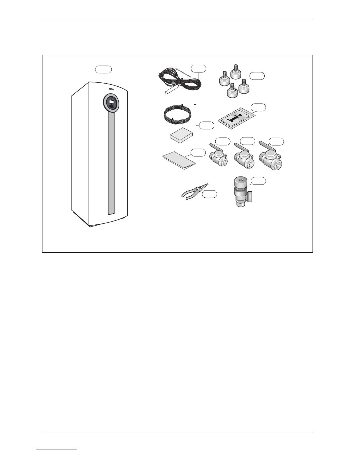
2 Included in the delivery
Fig. 1
1 Heat pump
2 Flow sensor
3 Adjustable feet
4 Outdoor sensor
5 Warranty Card
6 Guides
7 Particle filter for hot water
8 Particle filter for the heating system
9 Particle filter for the collector circuit
10 Pliers for particle filter
11 Safety valve, 4 bar
11
1
2
4
5
6
10
3
6720645504-01.1I
9
8
7
Page 6
Installation and transport tools
6 720 645 504 (2011/04) en
6
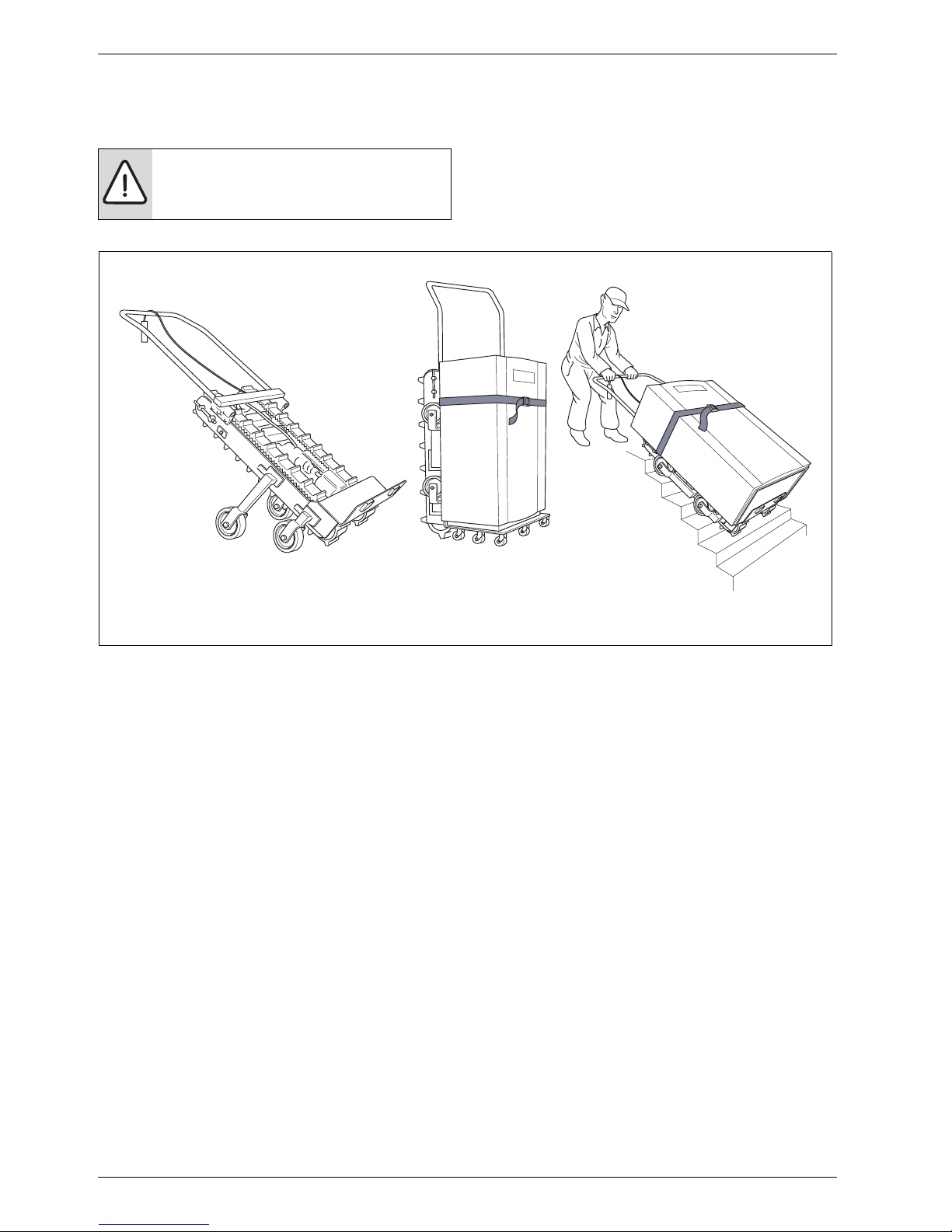
3 Installation and transport tools
The heat pump may be transported only with a handling
trolley/lift truck .
Fig. 2 Example of a handling trolley/lift truck that can be used during installation of a heat pump
DANGER: Personal injuries may occur. The
heat pump weighs between 330 and 360 kg.
B Never lift the heat pump by hand.
6 720 616 938-22.1I
Page 7
Lifting the heat pump
6 720 645 504 (2011/04) en
7
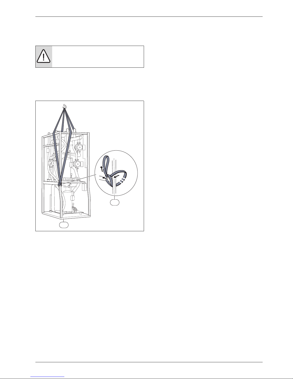
4 Lifting the heat pump
Remove the packaging and the transport pallet from the
heat pump. Dismantle also the front and side plates
before lifting the heat pump into the building.
Fig. 3 HC22-33 with lifting belts
1 HC 22-33 with lifting belt on opposite sides
2 Attach the lifting belts to the heat pump according to the
figure
DANGER: Personal injuries may occur. The
heat pump weighs between 330 and 360 kg.
B Never lift the heat pump by hand.
x 2
1
2
6 720 645 504-02.1I
Page 8

Product details
6 720 645 504 (2011/04) en
8
5 Product details
HC 22-33 are ground source pumps designed to be
supplemented with an external hot water heater.
5.1 Application area
The heat pump must only be used in a closed hot water
heating system according to BS EN 12828.
Other forms of use are not permitted. We take no
responsibility for damage occurring due to nonpermitted use.
5.2 Type overview
HC Ground source heat pump
kW Heat output 0/35 (EN 14511)
5.3 Type plate
The type plate is located on the roof plate of the heat
pump. Information about the heat pump's output, part
number, serial number and date of manufacture is stated
there.
5.4 Transport and storage
The heat pump should always be transported and stored
in an upright position. However, the heat pump may be
tilted temporarily, but must not be laid down.
The outer cover plates should be removed to avoid
damage if the heat pump is transported without the
supplied transport pallet.
The heat pump must not be stored at temperatures
below -10 °C.
5.5 Transport locking devices
The heat pump is furnished with transport locking
devices which prevent damage during transportation.
Unscrew the transport locking devices installed next to
the vibration dampers on the heat pump ( figure 9).
5.6 Positioning the heat pump
B The heat pump is placed indoors, on a level and stable
surface that withstands a weight of at least 400 kg.
B Adjust the rubber feet so the heat pump does not
lean.
B The ambient temperature around the heat pump must
be between 10 °C and 35 °C.
B The installer should take noice transfer to adjacent
areas into consideration when positioning the heat
pump.
B There must be a drain in the room where the heat
pump is placed. This ensures that water can easily be
carried away if there is a leak.
5.7 Checks before installation
B Installation of the heat pump should be performed by
a qualified installer.
B Before the heat pump is commissioned, the heating
system, hot water cylinder and the collector circuit
system, including the heat pump, must be filled and
vented.
B Check that all pipe connections are intact and have
not shaken loose during transportation.
B Wiring should be kept as short as possible to protect
the system from downtime, for example during a
thunderstorm.
B Heat pump installation, energy drilling and collector
installation must follow applicable regulations.
B Check the water quality ( page 24, VDI 2035).
5.8 Checklist
1. Position the heat pump on an even base. Adjust the
height using the adjustable feet.
2. Fit the valves, particle filters and a filling unit.
3. Install the incoming and outgoing pipes for the heat
pump, as well as the expansion vessel.
4. Connect the heating unit to the heating system.
5. Install the outdoor sensor and possible room sensors.
6. Fill and vent the heating and collector systems before
commissioning.
7. Carry out the external connections.
8. Connect the heating installation to the power supply.
9. Commission the heating installation by making all the
necessary settings on the control panel.
10. Check the heating installation after commissioning.
11. Top up more collector circuit fluid, if required.
Only qualified installers may carry out the
installation. The installer must follow
applicable rules and regulations and
recommendations from the supplier.
HC HC 22 HC 33
kW 21,0 33,8
Tab. 2 Type overview
Each heat pump installation is unique. The
following checklist will give you a general
description of how the installation should
be carried out.
Page 9
Product details
6 720 645 504 (2011/04) en
9
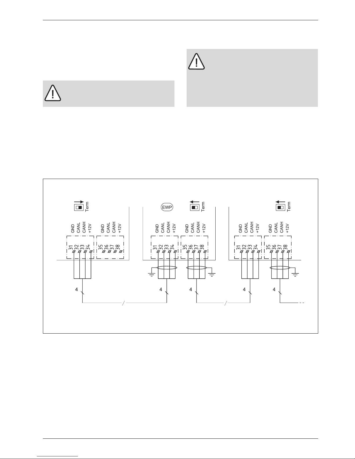
5.9 CAN-BUS
The various circuit boards in the heat pump are joined by
a communications cable, CAN-BUS. CAN (Controller
Area Network) is a two-wire system for communication
between microprocessor based modules/circuit boards.
Suitable cable for external laying is cable LIYCY (TP)
2x2x0.5. The cable must be twisted pair and screened.
The screen must only be earthed at one end and to the
chassis.
Maximum cable length is 30 m.
CAN-BUS cable must not be laid alongside power supply
cables. Minimum distance 100 mm. They may be laid
alongside sensor cables.
The connection between the circuit boards is by four
wires, because the 12V-supply between the circuit
boards must also be connected. The circuit boards have
markings for both the 12V and CAN-BUS connections.
Switch Term is used to mark the start and end of a CANBUS loop. Ensure that the correct circuit board is
terminated and that all other switches are in the
opposite position.
Fig. 4
GND Earth
CANL CAN low
CANH CAN high
+12V Connection 12V
EWP Heat pump
CAUTION: Interference.
B The CAN-BUS cable must be screened
and laid separately from the power cable.
CAUTION: Do not mix up the 12V and CANBUS connections!
The processors are destroyed if 12V is
connected to the CAN-BUS.
B Check that the four cables are connected
to the contacts with the corresponding
marking on the circuit board.
6 720 614 967-31.2I
CAN-BUS
CAN-BUS
Page 10
Product details
6 720 645 504 (2011/04) en
10
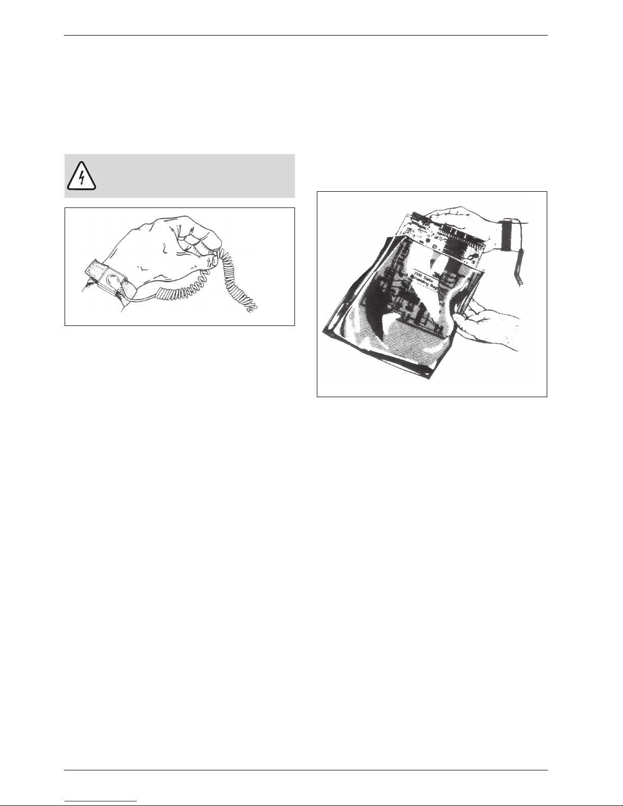
5.10 Handling circuit boards
Circuit boards with control electronics are sensitive to
discharges of static electricity (ESD – ElectroStatic
Discharge) when handled. To prevent damaging the
components, special care is therefore required when
handled.
Fig. 5 Bracelet
Damage is usually latent, and a circuit board can operate
impeccably during commissioning but show signs of
problems later. Charged objects may only be
problematic if they are in close proximity to the
electronics. Keep a distance of at least one metre from
expanded polystyrene, protective plastic and other
packaging, synthetic material (e.g. fleeces) and similar
before starting work.
A condition for good ESD protection is a groundconnected bracelet when handling electronics. This
bracelet must be put on before opening the screened
metal bag/packaging or before exposing an installed
board. The bracelet must be worn until the circuit board
is enclosed in its screen packaging or closed electric
box. Replaced, returned circuit boards must be handled
in the same way.
Fig. 6
CAUTION: Never grasp a circuit board
without wearing a ground-connected
bracelet.
6 720 614 366-24.1I
6 720 614 366-25.1I
Page 11

Heating, general
6 720 645 504 (2011/04) en
11
6 Heating, general
6.1 Circuits for heating
• Circuit 1; the first circuit is included by default in the
control unit and is controlled by the installed flow
sensor, possibly in combination with an installed
room sensor.
• Circuit 2 (mixed); control of circuit 2 is also included
by default in the control unit and only needs to be
supplemented with a mixing valve, circulation pump
and flow sensor and possibly with an additional room
sensor.
• Circuit 3-4 (mixed); control of up to 2 additional
circuits is optional. Each circuit is then fitted with a
mixing valve module, circulation pump, flow sensor
and a possible room sensor.
6.2 Control methods for heating
• Outdoor sensor; a sensor is fitted on the outside wall
of the house. The sensor sends signals to the control
unit in the heat pump. Control with an outdoor sensor
means that the heat pump automatically regulates the
heating in the house depending on the outdoor
temperature. The customer determines the
temperature of the heating system in relation to the
outdoor temperature by setting the heat curve on the
control unit.
• Outdoor sensor and room sensors (one room sensor
per circuit is possible); Control with outdoor sensor
supplemented with room sensor(s) means that one
(or several) sensors are mounted in a central location
inside the house. They are connected to the heat
pump and provide the control unit with information
about the current room temperature. The signal
affects the flow temperature. For example, it falls
when the room sensor indicates a higher temperature
than the one set. Room sensors are used when factors
other than the outdoor temperature influence the
indoor temperature of the house. For example, this
can be when a stove or fan-assisted radiator is used in
the house, or if the house is sensitive to the wind or
exposed to direct sunlight.
6.3 Time control for heating
• Program control; The control unit offers a possibility
to define two individual programs for time control of
the heating.
• Holiday; the control unit has a program for holiday
mode, which means that during the selected period
the room temperature changes to a lower or higher
level. The program also allows switching off hot water
production.
• External control; the control unit can make settings
for external control, which means that the
preselected function is performed when the control
unit senses an input signal.
Circuit 1 must always be installed and used.
Circuits 2 through 4 cannot have a higher
flow temperature than circuit 1. This means
that underfloor heating on circuit 1 cannot
be combined with radiators on another
circuit. Room temperature reduction for
circuit 1 can affect other circuits in some
cases.
When the Use temperature from circuit
with highest temperature function under
Circuit 1 is used, the heat curve for Circuit
1 does not need to be adapted to the mixed
circuits. The heat pump automatically
selects the highest flow temperature set
point value.
It is only the room where the room sensor is
located that can influence regulation of the
temperature for the relevant heating circuit.
Page 12

Heating, general
6 720 645 504 (2011/04) en
12
6.4 Operating modes
• Without additional heat; the heat pump is sized so as
to cover at least 100 % of the peak output of the
house.
– This choice is not in the control, choose Mixed
additional heat at Start-up and thereafter Block
additional heat in the menu for additional heat
( Chapter 16.7).
• With electrical additional heat; the heat pump is
sized to cover less than the peak output of the house.
An additional electric heat source covers the
difference. The additional electric heat source is
controlled by a 0-10 V signal which is connected to
the mixing valve output E71.E1.Q71 on the PEL board
( Chapter 11.6.5). Otherwise, the control of the
additional electric heat source functions in the same
way as the control of the mixed additional heat
source. The mixing valve control delay should be set
to 0, since it unnecessarily extends the start delay of
the additional heat ( Chapter 16.7).
• With mixed additional heat; mixed additional heat
source which is allowed to work in parallel with the
heat pump. Connection E71.E1.Q71
( Chapter 11.6.3). The additional heat is also used
in alarm mode.
For production of extra hot water and hot water peak,
an additional electric heat source is required in the
hot water heater.
For all operating modes shall Mixed
additional heat be used.
An additional electric heat source should
always be installed in the hot water heater if
the heat pump should supply more than 2
flats.
If an oil/gas boiler is used as a mixed
additional heat source, the boiler can be
installed in such a way as to generate hot
water, extra hot water and hot water peak.
In this case, an additional electric heat
source is not required in the hot water
heater.
Page 13
Dimensions and clearance
6 720 645 504 (2011/04) en
13
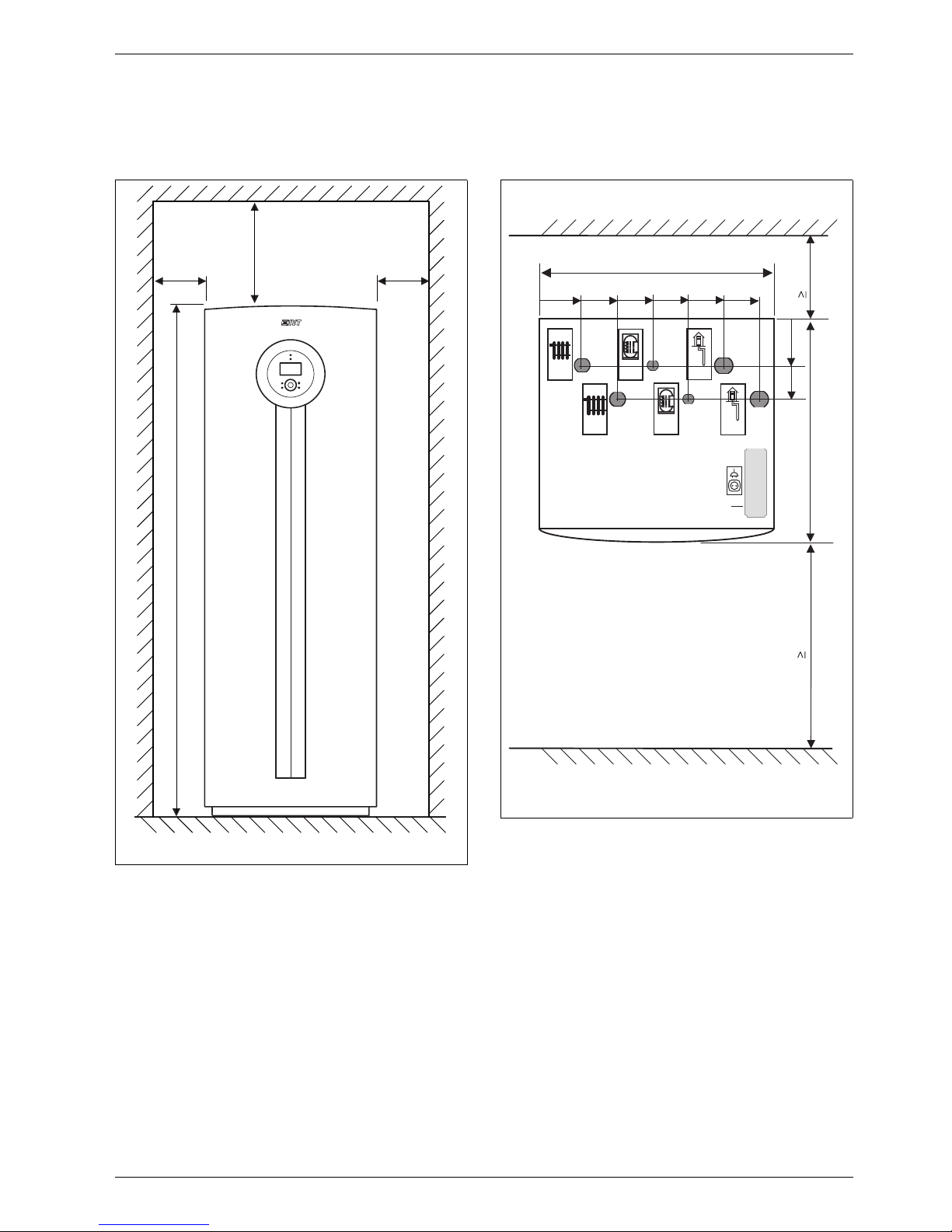
7 Dimensions and clearance
7.1 HC 22 - 33
Fig. 7 Front view
Fig. 8 Top view
All dimensions are stated in mm.:
A Collector circuit out
B Collector circuit in
C Return, hot water heater
D Flow, hot water heater
E Heat transfer fluid in
F Heat transfer fluid out
G Electrical connections
≥100 ≥350
≥600
1640
6 720 645 504-03.1I
E
B
A
F
C
D
700
810
300
135
230
1200
G
100
200
300
400
500
600
6 720 614 967-8.2I
Page 14
Technical information
6 720 645 504 (2011/04) en
14
8 Technical information
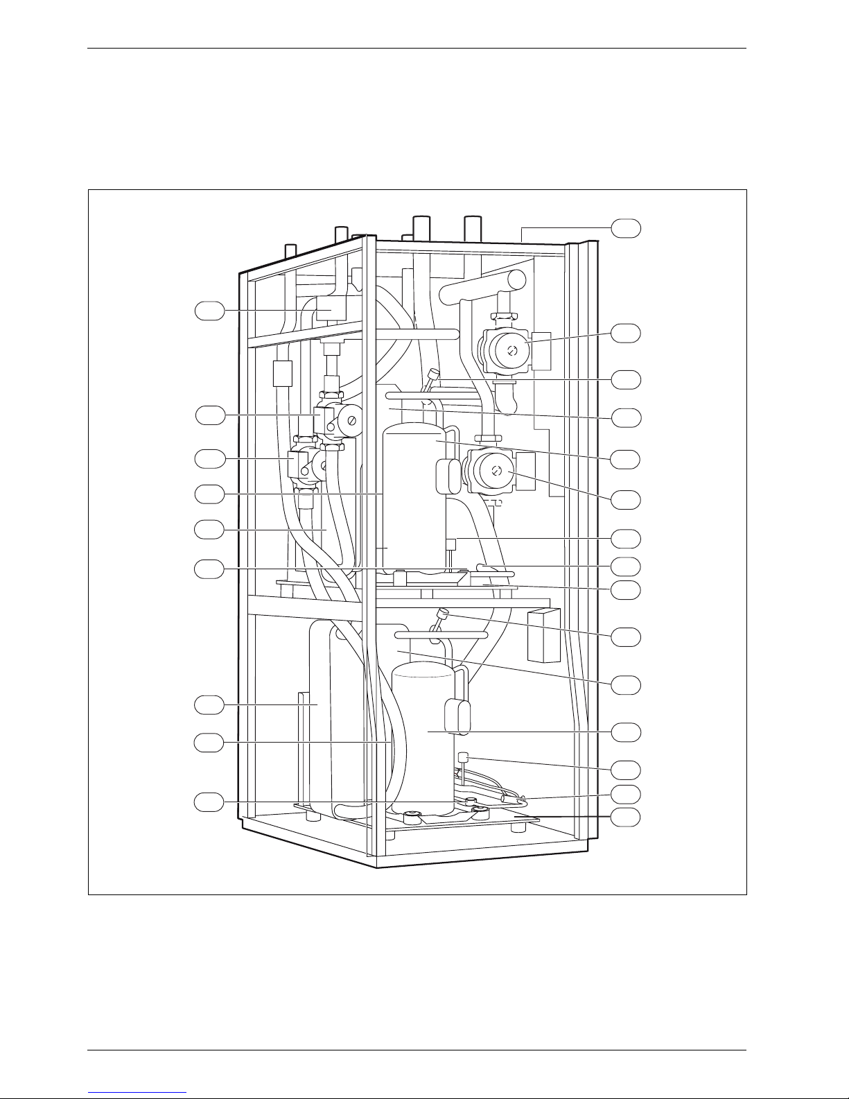
8.1 Component parts
8.1.1 HC 22 - 33
Fig. 9
1 Type plate
2 Collector circuit pump
3 Heat carrier pump
4 Low pressure switch
5 Condenser
6 Compressor (1 and 2)
7 Evaporator
8 Sight glass
9 High pressure switch
10 Expansion valve
11 3-way valve
12 Drying filter
13 Transport locking devices (2) and Vibration dampers (2)
6 720 614 967-5.1I
8
5
5
3
3
8
11
12
12
2
4
2
6
9
4
6
9
10
13
1
7
7
10
13
Page 15

Technical information
6 720 645 504 (2011/04) en
15
8.2 System solutions
8.2.1 System solution explanations
Detailed system solutions can be found in
the product's planning documentation.
E10
E10.T2 Outdoor sensor
Tab. 3 E10
E11 Circuit 1
E11.C101 Expansion vessel
E11.C111 Buffer tank
E11.F101 Safety valve
E11.F111 Automatic air vent
E11.G1 Heating circuit pump
E11.P101 Pressure gauge
E11.P111 Thermometer
E11.P112 Thermometer
E11.Q101 Shut-off valve
E11.Q102 Shut-off valve
E11.R101 Non-return valve
E11. T1 Flow sensor
E11.TT Room sensor
Tab. 4 E 11 Circuit 1
E12 Circuit 2
E12.G1 Heating circuit pump
E12.P112 Thermometer
E12.Q101 Shut-off valve
E12.Q102 Shut-off valve
E12.Q11 Mixing valve
E12.R101 Non-return valve
E12.T1 Flow sensor
E12.T5 Room sensor
Tab. 5 E12 Circuit 2
E21 Compressor 1
E21 Heat pump
E21.F111 Automatic air vent
E21.G2 Heat carrier pump
E21.G3 Collector circuit pump
E21.Q102 Shut-off valve
E21.Q21 3-way valve
E21.R101 Non-return valve
E21.R102 Non-return valve
E21.T8 Heat transfer fluid out
E21.T9 Heat transfer fluid in
E21.T10 Collector circuit in
E21.T11 Collector circuit out
E21.V102 Filter
Tab. 6 E21 Compressor 1
E22 Compressor 2
E22 Heat pump
E22.F101 Safety valve
E22.G2 Heat carrier pump
E22.G3 Collector circuit pump
E22.Q101 Shut-off valve
E22.Q21 3-way valve
E22.R101 Non-return valve
E22.R102 Non-return valve
E22.T8 Heat transfer fluid out
E22.T9 Heat transfer fluid in
E22.T10 Collector circuit in
E22.T11 Collector circuit out
E22.V101 Filter
Tab. 7 E22 Compressor 2
Page 16

Technical information
6 720 645 504 (2011/04) en
16
E31 Collector circuit
E31 Collector circuit, compressor 1
E31.C101 Expansion vessel
E31.F101 Safety valve
E31.F102 Safety valve
E31.F111 Automatic air vent
E31.Q21 Ball valve filling unit
E31.Q22 Ball valve filling unit
E31.Q23 Shut-off valve
E31.Q24 Shut-off valve
E31.V101 Filter
Tab. 8 E31 Collector circuit
E41 and E42 Domestic hot water tank 1 and 2
E41 Hot water heater 1
E41.E1 Hot water electric heater
E41.E1.G1 Circulation pump
E41.F101 Safety valve
E41.F102 Safety valve
E41.G6 Circulation pump hot water
E41.P111 Thermometer
E41.P112 Thermometer
E41.Q101 Shut-off valve
E41.Q104 Shut-off valve
E41.Q105 Shut-off valve
E41.Q106 Shut-off valve
E41.Q111 Balancing valve
E41.R101 Non-return valve
E41.R102 Non-return valve
E41.T3 Hot water sensor
E41.V41 Hot water
E41.W41 Cold water
E42 Hot water heater 2
Tab. 9 E41, E42 DHW tank 1, 2
E71 Additional heat
E71 Additional heat
E71.E1.F101 Safety valve
E71.E1.F111 Automatic air vent
E71.E1.G71 Circulation pump
E71.E1.P111 Thermometer
E71.E1.P101 Pressure gauge
E71.E1.Q1Q1 Shut-off valve
E71.E1.Q1Q2 Shut-off valve
E71.E1.Q71 Mixing valve
Tab. 10 E71 Additional heat
Page 17
Technical information
6 720 645 504 (2011/04) en
17
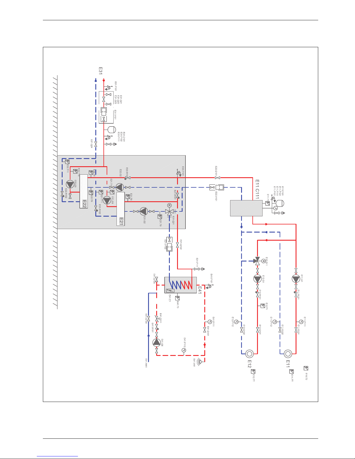
8.2.2 System solution without additional heat
Fig. 10 Heating circuit and buffer tank without additional heat (
Chapter 8.2.1, 8.3)
6 720 616 938-23.1I
Page 18
Technical information
6 720 645 504 (2011/04) en
18
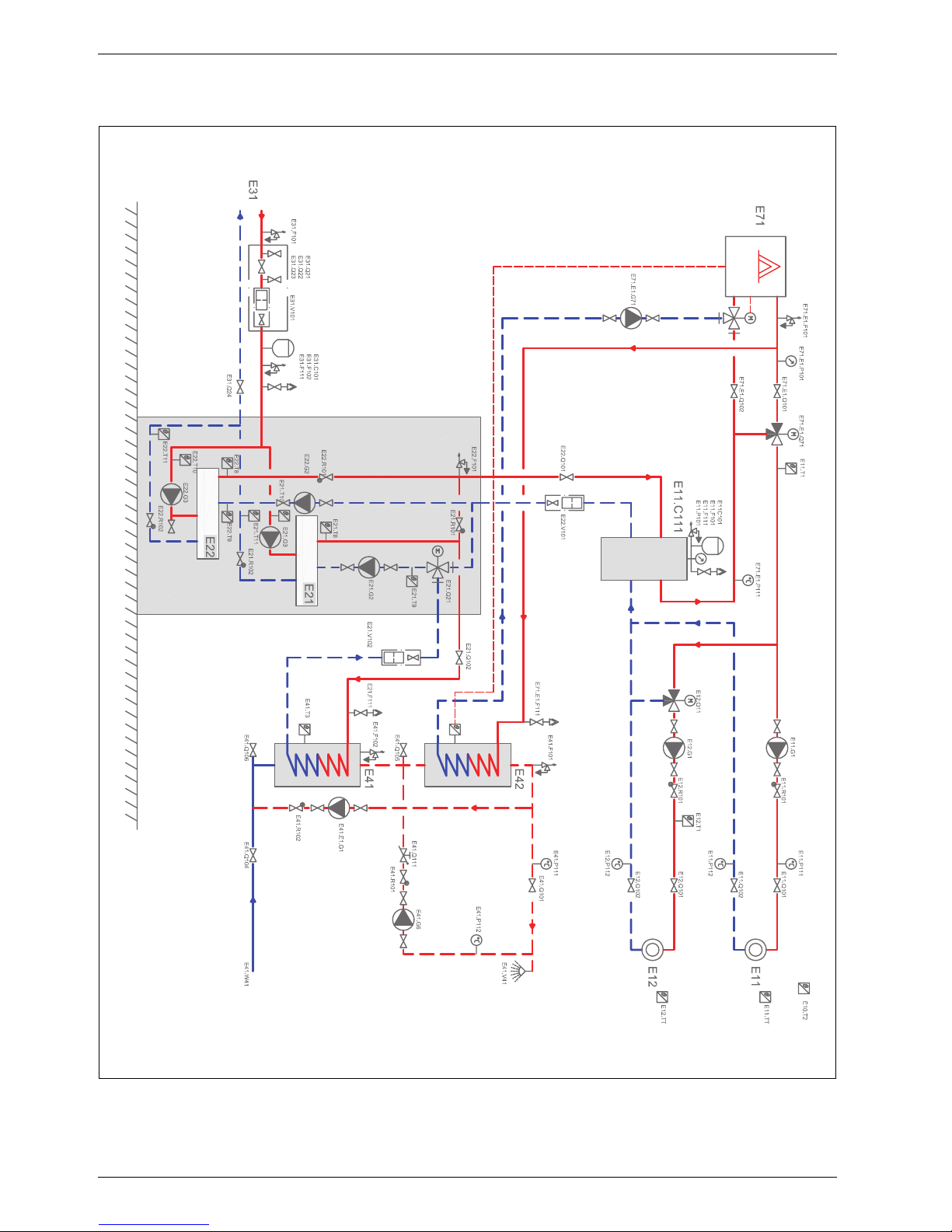
8.2.3 System solution with mixed additional heat
Fig. 11 Heating circuit, buffer tank and mixed additional heat (
Chapter 8.2.1, 8.3)
6 720 616 938-26.1I
Page 19
Technical information
6 720 645 504 (2011/04) en
19
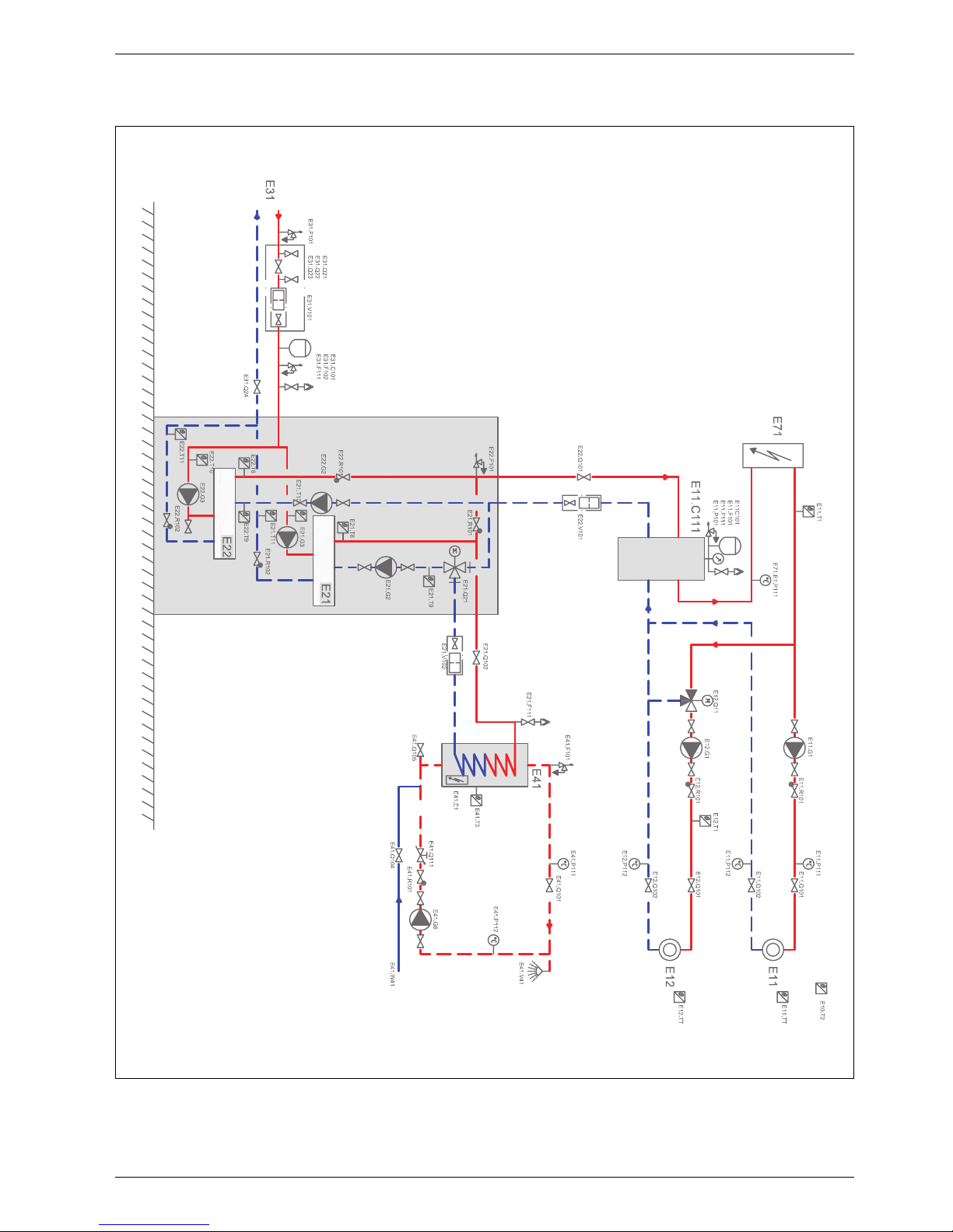
8.2.4 System solution with electric additional heat
Fig. 12 Heating circuit, electric additional heat and buffer tank (
Chapter 8.2.1, 8.3)
6 720 616 938-25.1I
Page 20

Technical information
6 720 645 504 (2011/04) en
20
8.3 Functional description of system solutions
System without additional heat ( Chapter 8.2.2)
Heating
Heat for E11 is taken directly from buffer tank E11.C111.
Heat for E12 is taken from buffer tank E11.C111 and is
shunting to the set temperature using mixing valve
E12.Q11. The heat pump supplies heat to E11.C111 and
keeps the temperature set on E11.T11 by starting one
compressor at a time when the temperature is too low
and stopping one compressor at a time when the
temperature is too high.
Hot water
When the temperature in hot water heater E41.T3 falls
below the set limit, E21.Q21 switches over to water
heating and compressor E21 starts. Water heating
continues until the temperature of E21.T8 exceeds the
set stop limit.
Pump control
E11.G1 and E12.G1 start at low outdoor temperature
and stop at high outdoor temperature. E21.G2 and
E21.G3 are in operation when compressor E21 is in
operation. E22.G2 and E22.G3 are in operation when
compressor E22 is in operation. E41.G6 is in operation
at set times.
System with mixed additional heat
( Chapter 8.2.3)
Additional heat and heat pump work in parallel
Heat for E11 is taken directly from buffer tank E11.C111,
with possible afterheating by E71. Heat for E12 is taken
from buffer tank E11.C111, with possible afterheating by
E71, and is released by shunting at the set temperature
using mixing valve E12.Q11. The heat pump supplies
heat to E11.C111 in order to keep the temperature set
on E11.T11 by starting one compressor at a time when
the temperature is too low and stopping one
compressor at a time when the temperature is too high.
If the heat pump does not manage to supply the set
temperature by itself, additional heat E71.E1.Q71 is
activated and regulates E11.T1 to the set temperature.
Additional heat and heat pump work separately
When the heat pump is responsible for all of the heating,
it supplies heat to E11.C111 and keeps the temperature
set on E11.T11 by starting one compressor at a time
when the temperature is too low and stopping one
compressor at a time when the temperature is too high.
When the heat pump is in operation, boiler E71 is
responsible for all of the heat production. Heat for E11
is taken from buffer tank E11.C111 or from E71. Heat for
E12 is taken from buffer tank E11.C11 or from E71 and
is shunted to the set temperature using mixing valve
E12.Q11. Switch between heat pump and additional
heat operation can result from low outdoor temperature,
temporary stop of the energy supply to the heat pump or
activation of external input for blocking the heat pump.
Hot water
The hot water is preheated in E41 which is heated by the
heat pump. When the temperature in hot water heater
E41.T3 falls below the set limit, E21.Q21 switches over
to water heating and compressor E21 starts. Water
heating continues until the temperature of E21.T8
exceeds the set stop limit. The hot water is afterheated
in E42 which is heated by additional heat E71. The
heating of the hot water circulation via E41.G6 is done
completely by E42. Additional heat E71 exercises full
control and regulation of the temperature in hot water
heater E42.
Pump control
E11.G1 and E12.G1 start at a low outdoor temperature
and stop at a high outdoor temperature. E21.G2 and
E21.G3 are in operation when compressor E21 is in
operation. E22.G2 and E22.G3 are in operation when
compressor E22 is in operation. E41.G6 are in operation
at the set times. E41.E1.G1 ( Chapter 11.9) is
controlled by the heat pump and is used for thermal
disinfection of E41.
High temperature systems
In some heating systems the return temperature may at
times exceed 55 °C. In such cases the heat pump stops
(T9 > 55 °C) and restarts when E11.T1 becomes less
than 65 °C.
Page 21

Technical information
6 720 645 504 (2011/04) en
21
System with electric additional heat
( Chapter 8.2.4)
Heating
Heat for E11 is taken directly from buffer tank
E11.C111, with possible afterheating by E71. Heat for
E12 is taken from buffer tank E11.C111, with possible
afterheating by E71, and is shunted to the set
temperature using mixing valve E12.Q11. The heat pump
supplies heat to E11.C111 and keeps the temperature
set on E11.T11 by starting one compressor at a time in
the heat pump when the temperature is too low and
stopping one compressor at a time when the
temperature is too high. If the heat pump does not
manage to supply the set temperature by itself,
additional heat is activated, controlling the output via 010 V signal so as to keep the set temperature.
Hot water
When the temperature in hot water heater E41.T3 falls
below the set limit, E21.Q21 switches over to water
heating and compressor E21 starts. Water heating
continues until the temperature of E21.T8 exceeds the
set stop limit.
Pump control
E11.G1 and E12.G1 start at low outdoor temperature
and stop at high outdoor temperature. E21.G2 and
E21.G3 are in operation when compressor E21 is in
operation. E22.G2 and E22.G3 are in operation when
compressor E22 is in operation. E41.G6 is in operation
at set times.
This system solution is also suitable for 010V output-controlled gas/oil-fired boiler.
Enter Yes for Acknowledge hot water
additional heat (Chapter 16.7) in all
system solutions.
Page 22
Technical information
6 720 645 504 (2011/04) en
22
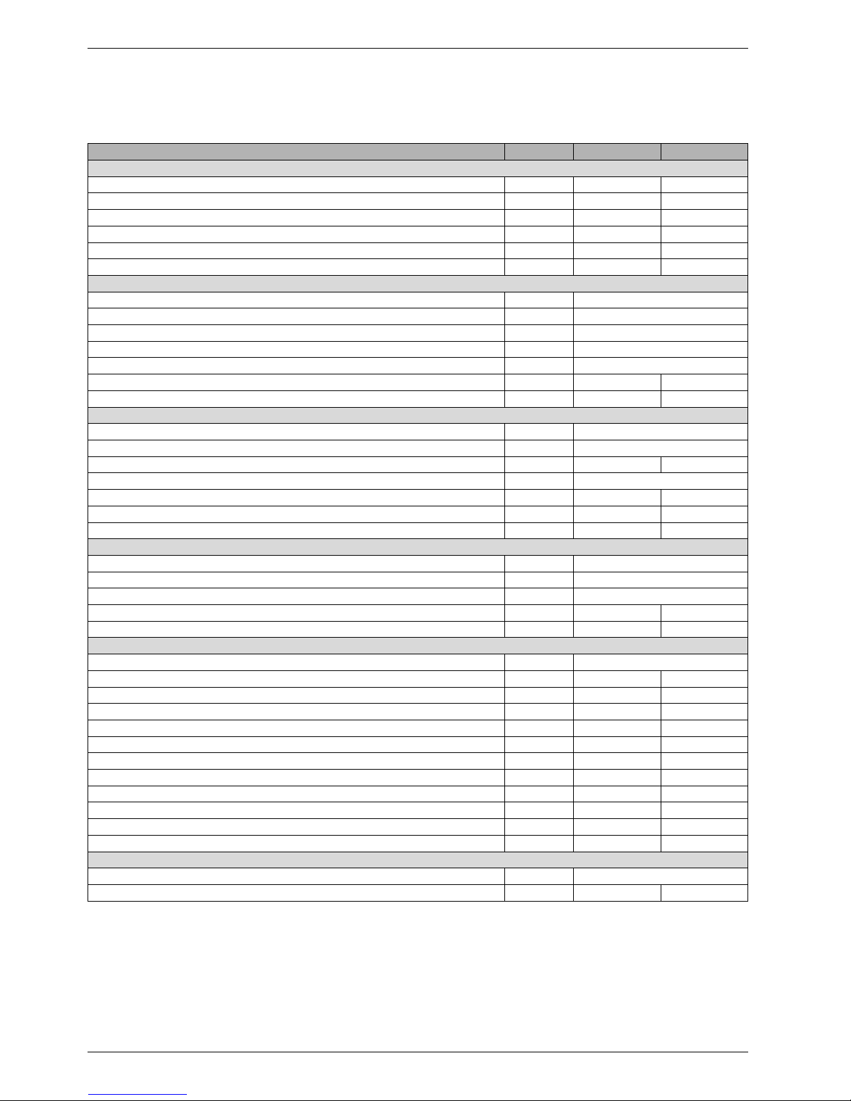
8.4 Technical information
8.4.1 HC 22 - 33
Unit HC 22 HC 33
Liquid/water operation
Emitted output / COP (0/35) EN14511
1)
1) The indicated values are measured according to WPZ test methods.
kW 21.0/4.4 33.8/4.2
Emitted output / COP (0/45) EN14511
1)
kW 19.9/3.5 31.6/3.2
Emitted output / COP (0/35) EN255
1)
kW 21.6/4.8 34.2/4.4
Emitted output / COP (10/35) EN255
1)
kW 26.4/5.8 41.7/5.2
Max. cooling effect (0/35) kW 17 26
Max. cooling effect (10/35) kW 23 34
Collector circuit
Connection, collector circuit DN40, 1½ “
Working pressure collector circuit max/min bar 4 / 0.5
Incoming temperature collector circuit max/min °C 22 / -5
Outgoing temperature collector circuit min. °C -8
Mixture Ethylene glycol max/min % 35 / 30
Nominal flow collector circuit (max deviation 15%) l/s 1.3 2.3
Permitted ext. pressure drop collector circuit kPa 65 44
Heating system
Buffer tank connections DN 32, 1¼ “
Tap hot water connections DN 25, 1“
Nominal flow hot water (max deviation 15%) l/s 0.28 0.45
Working pressure heating system max/min bar 4 / 0.5
Flow buffer tank max/min l/s 0.74/0.52 1.1/0.82
Max. ext. pressure drop buffer tank at max. flow kPa 30 20
Max. ext. pressure drop buffer tank at min. flow kPa 40 40
Compressor
Step 1 (no. 1) Mitsubishi Scroll
Step 2 (no. 2) Mitsubishi Scroll
Max. flow temperature (no. 1/no. 2) °C 65/65
Refrigerant R 407C (no. 1/no. 2)
2)
2) Global Warming Potential, GWP
100
= 1526
kg 2,4/2,4 2,6/2,6
Sound level
3)
3) The sound level is the acoustic energy that the heat pump emits and is not affected by the surroundings. On the other hand, the
sound pressure level is affected by the surroundings and is approx. 11dBA lower when measured at a distance of 1 m in a free
field.
dBA 51 53
Electrical data
Electrical connection (acc. to EN 60204-1) 400V 3N~50Hz
Fuse gL- gG / characteristic D (automatic) A 25 32
Max. short-circuit impedance soft starter Ω 0,42 0,47
Max. operating current A 17 22,3
Start current with soft starter A 29 30
Nominal output (0/50) kW 6,7 10,8
Nominal output (0/35) kW 5,5 8,7
Maximum effect kW 10,5 14,1
Collector circuit pump output at max. speed (no. 1/no. 2) W 310/310 390/390
Collector circuit pump output at min. speed (no. 1/no. 2) W 290/290 360/360
Heat carrier pump output at max. speed (no. 1/no. 2) W 91/91 124/124
Heat carrier pump output at min. speed (no. 1/no. 2) W 49/49 61/61
General
Dimensions (height x depth x width) mm 700 x 750 x 1620
Weight kg 330 351
Tab. 11 Teknisk information
Page 23

Technical information
6 720 645 504 (2011/04) en
23
8.4.2 Motor cut-out compressor
8.4.3 Circulation pumps
8.4.4 Measurement values for temperature sensors
Compressor HC 22 HC 33
No. 1 8 A 13 A
No. 2 8 A 13 A
Tab. 12 Motor cut-out settings, compressor
Collector circuit pump
(G3)
HC 22 HC 33
No. 1 Wilo TOP-S 30/10 TOP-S 30/10
No. 2 Wilo TOP-S 30/10 TOP-S 30/10
Tab. 13 Built-in collector circuit pumps
Heat carrier pump
(G2)
HC 22 HC 33
No. 1 Wilo RS-25/6 RS-25/7
No. 2 Wilo RS-25/6 RS-25/7
Tab. 14 Built-in heat carrier pumps
°C Ω
T...
°C Ω
T...
°C Ω
T...
°C Ω
T...
–40 154300 –5 19770 30 3790 65 980
–35 111700 0 15280 35 3070 70 824
–30 81700 5 11900 40 2510 75 696
–25 60400 10 9330 45 2055 80 590
–20 45100 15 7370 50 1696 85 503
–15 33950 20 5870 55 1405 90 430
–10 25800 25 4700 60 1170
Tab. 15 Measurement values for temperature sensors
Page 24

Regulations
6 720 645 504 (2011/04) en
24
9Regulations
The following regulations and requirements must be
observed:
• The responsible power supply company's local
regulations and requirements, including the
corresponding special rules (TAB)
• BImSchG, Section 2 on installations which do not
require permits
• TA Lärm Technical Instruction on Noise Protection -
(general regulation in accordance with the Federal
Emission Control Act)
• National building regulations
• EnEG (Energy Saving Act)
• EnEV (German regulations on energy saving thermal
insulation and energy saving building design)
• EN 60335 (Safety of electric and similar household
appliances)
part 1 (General requirements)
Part 2-40 (Particular requirements for electrical heat
pumps, air-conditioners and dehumidifiers)
• EN 12828 (Heating systems in buildings. Design for
water-based heating systems)
• DVGW, Wirtschafts- und Verlagsgesellschaft, Gas-
und Wasser GmbH - Josef-Wirmer-Str. 1–3 53123 Bonn
– Worksheet W 101
Guidelines for drinking water protection areas;
part I: protection areas for groundwater
• The following DIN standards:DIN 1988, TRWI
(Technical Regulations for Drinking Water
Installations),DIN VDE 0100, Part 701 (Installation of
High-Power Equipment with Rated Voltages up to
1000 V, Rooms with Bath or Shower),DIN 4751
(Heating Systems; Safety Systems for Water Heating
Systems with Flow Temperatures up to 110 °C),DIN
4807 (Expansion Vessels)Beuth-Verlag GmbH Burggrafenstraße 6 -10787 Berlin
– DIN 1988, TRWI (Technical Regulations for
Drinking Water Installations)
– DIN 4108 (Thermal Insulation and Energy Economy
in Buildings)
– DIN 4109 (Sound Insulation in High Buildings)
– DIN 4708 (Central Hot Water Installations)
– DIN 4807 and EN 13831, respectively (Expansion
Vessels)
– DIN 8960 (Refrigerants -Requirements and
Symbols)
– DIN 8975-1 (Refrigerating Plants - Safety Principles
for Design, Equipment and Installation Interpretation)
– DIN VDE 0100, (Installation of High-Power
Equipment with Rated Voltages up to 1000 V)
– DIN VDE 0105 (Operation of Power Installations)
– DIN VDE 0730 (Regulations for Devices with
Electromotive Drive for Domestic Use and Similar
Purposes)
• VDI guidelines, Verein Deutscher Ingenieure e.V. -
P.O. Box 10 11 39 - 40002 Düsseldorf
– VDI 2035 Sheet 1
1)
: Prevention of damage in water
heating installations and scale formation in
domestic hot water supply installations and water
heating installations
– VDI 2035 Sheet 2
2)
: Prevention of water corrosion
in the heating system
– VDI 2081 Sound production and reduction in
ventilation systems
– VDI 2715 Noise reduction at domestic hot water
and central heating systems
– VDI 4640 Thermal use of the underground,
Sheet 1: Fundamentals, approvals, environmental
aspects;
Sheet 2: Ground source heat pump systems
• Austria:
– örtliche Bestimmungen und regionale
Bauordnungen
– Vorschriften der Versorgungsnetzbetreiber (VNB)
– Vorschriften der Wasserversorgungsunternehmen
– Wasserrechtsgesetz von 1959 in gültiger Fassung
– ÖNORM H 5195-1 Verhütung von Schäden durch
Korrosion und Steinbildung in geschlossenen
Warmwasserheizungsanlagen bis 100 °C
– ÖNORM H 5195-2 Verhütung von Frostschäden in
geschlossenen Heizungsanlagen
• Switzerland: kantonale und örtliche Vorschriften1
1) If the drinking water has a higher °dH than what is indicated in
VDI 2035, a water softener must be installed in the filling pipe
to the heating system - this in order to guarantee the function
of the heat pump. However, when the hardness is already
greater than 3 °dH, the performance of the heat pump will
deteriorate with time because of the lime deposits left on the
heat exchanger surfaces.
2) The standard discusses the problems but does not set any limit
values. This is why, we supplement with the following values:
Oxygen content, O
2
-0.5-1 mg/l. Carbon dioxide content, CO2 <1 mg/l. Chloride, Cl - <100 mg/l. Sulphate, SO4 - <100 mg/l. If
the drinking water exceeds the limit values for chloride or
sulphate content, an ion exchange filter must be installed in
the filling pipe for the heating system. Do not use any water
treatment additives except agents for raising the pH level, keep
the water clean.
Page 25

Installation
6 720 645 504 (2011/04) en
25
10 Installation
10.1 Collector system
Installation and filling
Installation and filling of the collector system should
comply with applicable laws and regulations. Soil used
for refilling around the collector hose must not contain
stones or other sharp objects. Pressure test the
collector system before refilling to ensure that the
system is watertight.
When cutting the collector, it is important that no dirt or
gravel enters the system. This can cause blockages in the
heat pump and damage components.
Condensation insulation
Condensation insulation should be mounted on all parts
of the collector circuit system.
Filling unit
A filling unit is required and should be installed close to
the collector circuit inlet.
Vents
To avoid operational disturbances because of air
bubbles, a microbubble separator with a venting nipple
is required and should be installed between the filling
unit and the heat pump.
Expansion vessel, safety valve, pressure gauge
The expansion vessel, safety valve and pressure gauge
are to be provided by the dealer.
Membrane expansion vessel in the collector circuit
Select membrane expansion vessel according to:
The values apply at a pre-pressure of 0.5 bar.
Antifreeze/Corrosion preventative
Freeze protection until –15 °C should be ensured. We
recommend the use of ethylene glycol.
10.2 Heating system
Flow over the heating system
When the heat pump works with a buffer tank, there can
be significant variations in the flow into the heating
system. However, there must be a certain minimum flow,
which is solved by:
In the event of a radiator system, the setting for the
radiator thermostats must be limited to a minimum
temperature of 18°C.
In the event of a floor heating system, a minimum water
flow must be guaranteed by ensuring that there are
circuits without room temperature control or with a
bypass in the floor heating distributor.
This guarantees cooling of the heating system's
circulation pump and correct measurements of the flow
sensor. A slight increase in flow rate above the minimum
flow is accepted.
Expansion vessel
Select expansion vessel in accordance with BS
EN 12828.
Particle filter
A particle filter for the heating system is included in the
delivery and should be installed on the connection for
heat transfer fluid in (heating system return).
A particle filter for the collector circuit is included in the
delivery and is installed between the filling unit and the
heat pump close to the connection for collector circuit
in.
A particle filter for hot water is included in the delivery
and should be installed on the connection for hot water
return.
See also the system solutions ( Chapter 8.2).
Ethylene glycol
Glycol is not normally used in the heating system. In
special cases, where increased protection is required,
glycol can be added with a maximum concentration of
15%. Heat pump performance will however decrease.
Safety valve
Pursuant to EN 12828, a safety valve should be used.
The safety valve must be installed vertically.
Only qualified installers may carry out the
installation. The installer must follow
applicable rules and regulations and
recommendations from the supplier.
Model Volume
HC 22 25 litres
HC 33 35 litres
Tab. 16 Volume membrane expansion vessel
WARNING:
B No other anti-freeze may be used in the
heating system.
Page 26
Installation
6 720 645 504 (2011/04) en
26
10.3 Siting the appliance
Noice transfer to adjacent areas must be taken into
consideration when choosing a position for the heat
pump ( Chapter 8.4 for sound levels).
10.4 Pipework preparations
B Connection pipes for the collector system, heating
system and possible hot water should be installed in
the premises to the heat pump location.
B An expansion vessel, a safety group and a pressure
gauge should be mounted in the heating circuit
(accessories).
B Mount a filling unit at a suitable place in the collector
circuit close to the inlet.
10.5 Flushing the heating system
The heat pump is a part in a heating system. Faults in the
heat pump can be caused by poor water quality in the
radiators/floor loops or air penetrating the system
continuously.
Oxygen causes corrosion products in the form of
magnetite and sediment.
Magnetite has a grinding effect on the heating system's
pumps, valves and components with turbulent flows
such as the condenser.
Heating systems which require regular filling or where
the heating water is not clear when drained, require
remedial measures before the installation of a heat
pump, for example the heating system must be fitted
with filters and vents.
Do not use any water treatment additives except agents
for raising the pH level. Recommended pH value is 7.5 –
9.
An intermediate heat exchanger is sometimes necessary
to protect the heat pump.
10.6 Setting up
B Remove packing, taking care to observe the
instructions on the packing.
B Remove the supplied accessories.
B Install the supplied adjustable feet and adjust the
height.
10.7 Heat insulation
All heat conducting pipes must have suitable heat
insulation, applied to current standards.
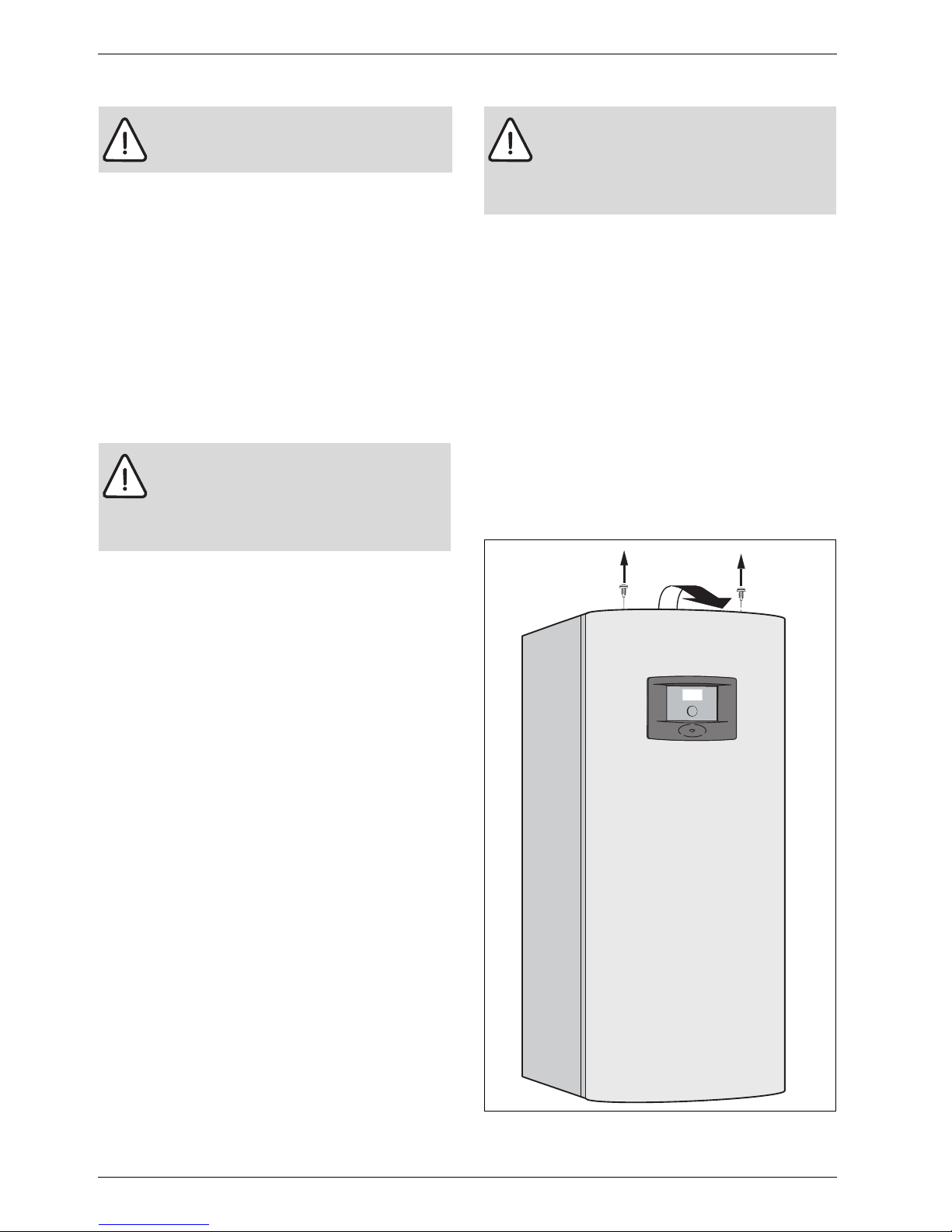
10.8 Removing the front panel
B Loosen the screws, tilt the front panel outwards and
take it off.
Fig. 13
WARNING:
B Never block the safety valve outlet.
CAUTION: The heat pump may become
damaged in the event of dirt or other
particles in the pipework.
B Flush out the system to remove all dirt
residues.
CAUTION: The heat pump may become
damaged in the event of dirt or other
particles in the pipework.
B Flush out the system to remove all dirt
residues.
1.
1.
2.
6 720 614 967-4.1I
Page 27
Installation
6 720 645 504 (2011/04) en
27
10.9 Temperature sensor installation
10.9.1 Flow sensor T1
B Operation mode without additional heat with buffer
tank. Install the sensor in the upper part of the tank.
See the installation manual for the buffer tank.
B Operation mode mixed additional heat (including
electric additional heat). Install the sensor in contact
with the flow pipe immediately after the mixing valve
(Q71) or after the additional electric heat.
10.9.2 Outdoor sensor T2
B Install the sensor on the coldest side of the house
(the north side). It must be protected from direct
sunlight, ventilation air or anything that can affect the
temperature measurement. The sensor must not be
installed directly beneath the roof.
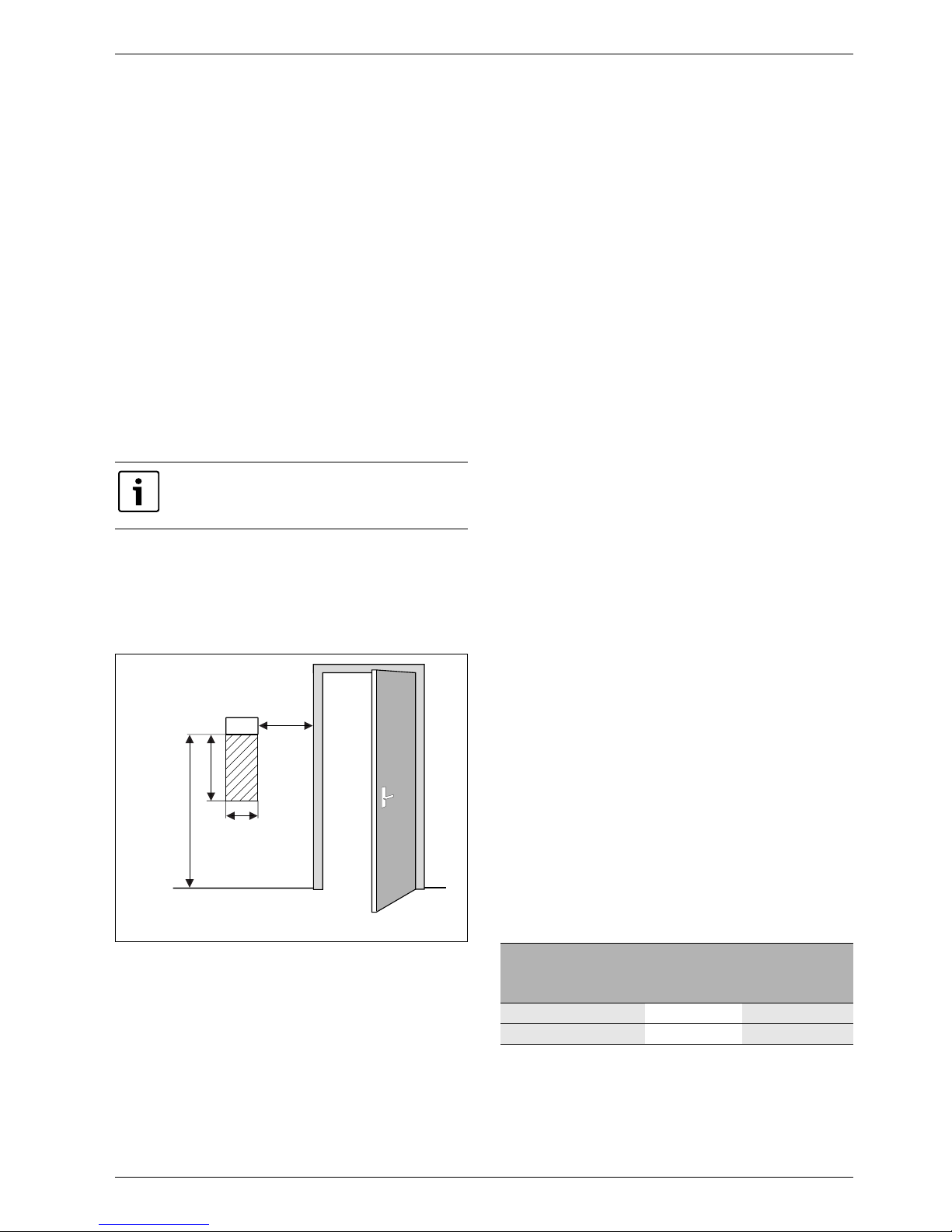
10.9.3 Room sensor T5 (accessory)
Installation location requirements:
• If possible, interior wall without drafts or heat
radiation.
• Unimpeded circulation of room air under room sensor
T5 (dotted area in figure 14 must be kept clear).
Fig. 14 Recommended installation location for room
sensor T5
10.10 Filling the heating system
B Open the heating system's valves.
B Open the tap on particle filter E22.V101 of the heating
system. Open valve E22.Q101.
B Fill up the heating system until the appropriate
pressure for the installation is reached. The maximum
permitted pressure is 4 bar.
B Vent the heating system.
B Drain some water out of buffer tank E11.C111 in
order to flush away possible particles from the tank.
Check and clean the particle filter if necessary.
B Check the pressure of the system and refill to the
appropriate pressure.
B Repeat the steps above if there is a lot of dirt in the
filter or tank.
B Check all connections for leaks.
10.11 Filling the hot water circuit
B Remove the cover of particle filter E21.V102. Position
the filter in an intermediate position.
B Position the 3-way valve E21.Q21 for heat production.
B Open shut-off valve E21.Q102 a bit and fill the circuit
carefully.
B Position the filter in operating mode and refit the
cover.
B Open the shut-off valve completely and perform
manual operation of the 3-way valve E21.Q21 in both
heating and hot water mode for venting.
B Check the pressure of the heating system and fill up,
if necessary, to a maximum of 4 bar.
B Check all connections for leaks.
10.12 Filling the collector system
The collector system is filled with collector circuit fluid
which must guarantee antifreeze protection down to
–15 °C. We recommend a mixture of water and glycol.
A rough estimate of the amount of collector circuit fluid
that is required in relation to the length of the collector
system and the inner diameter of the pipe can be made
using table 17.
It is only the room where the room sensor is
located that can influence regulation of the
temperature for the relevant heating circuit.
6 720 614 366-34.1I
0,3 m
0,3 m
0,6 m
1,2 - 1,5 m
T5
Inner diameter
Volume per metre
Single pipes
Double U
pipes
28 mm 0.62 l 2.48 l
35 mm 0.96 l 3.84 l
Tab. 17 Amount of collector circuit fluid
Page 28
Installation
6 720 645 504 (2011/04) en
28
The following description of filling presupposes the use
of the filling station accessory. Follow corresponding
steps if other equipment is used.
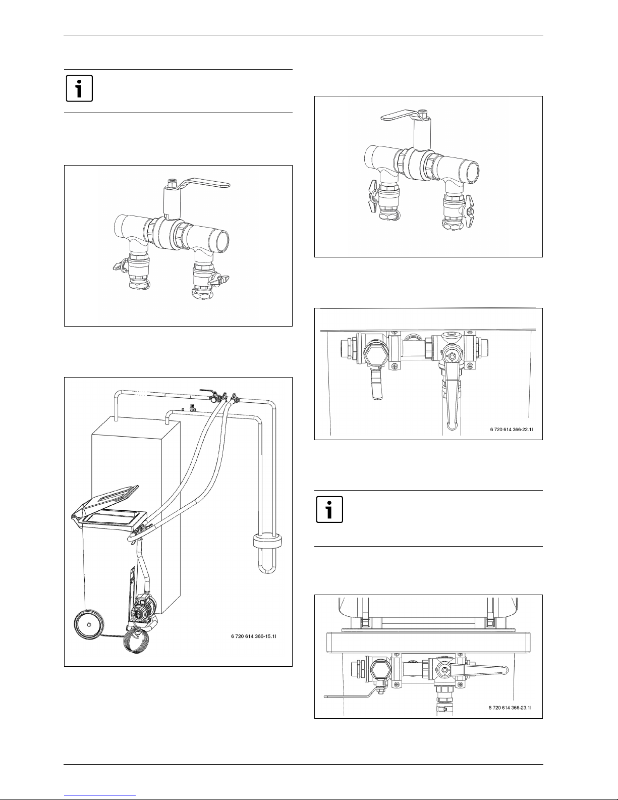
Fig. 15 Example of a filling unit
B Connect two hoses from the filling station to the
filling unit ( Figure 16).
Fig. 16 Filling with filling station
B Fill the filling station with collector circuit fluid. Fill
water before you fill antifreeze.
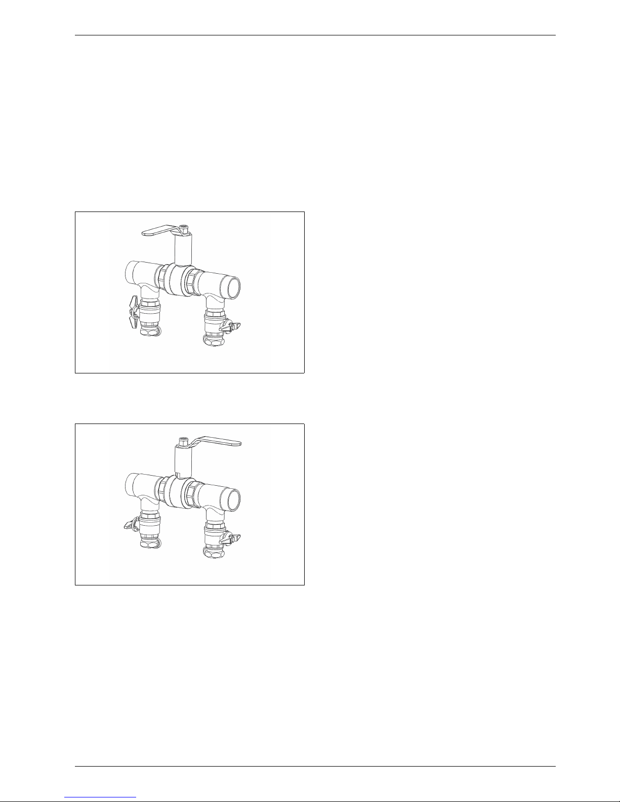
B Turn the valves on the filling unit so that they are in
filling position ( Figure 17).
Fig. 17 Filling unit in filling position
B Turn the valves on the filling station so that they are
in mixing position ( Figure 18).
Fig. 18 Filling station in mixing position
B Start the filling station (pump) and mix the collector
circuit fluid for at least two minutes.
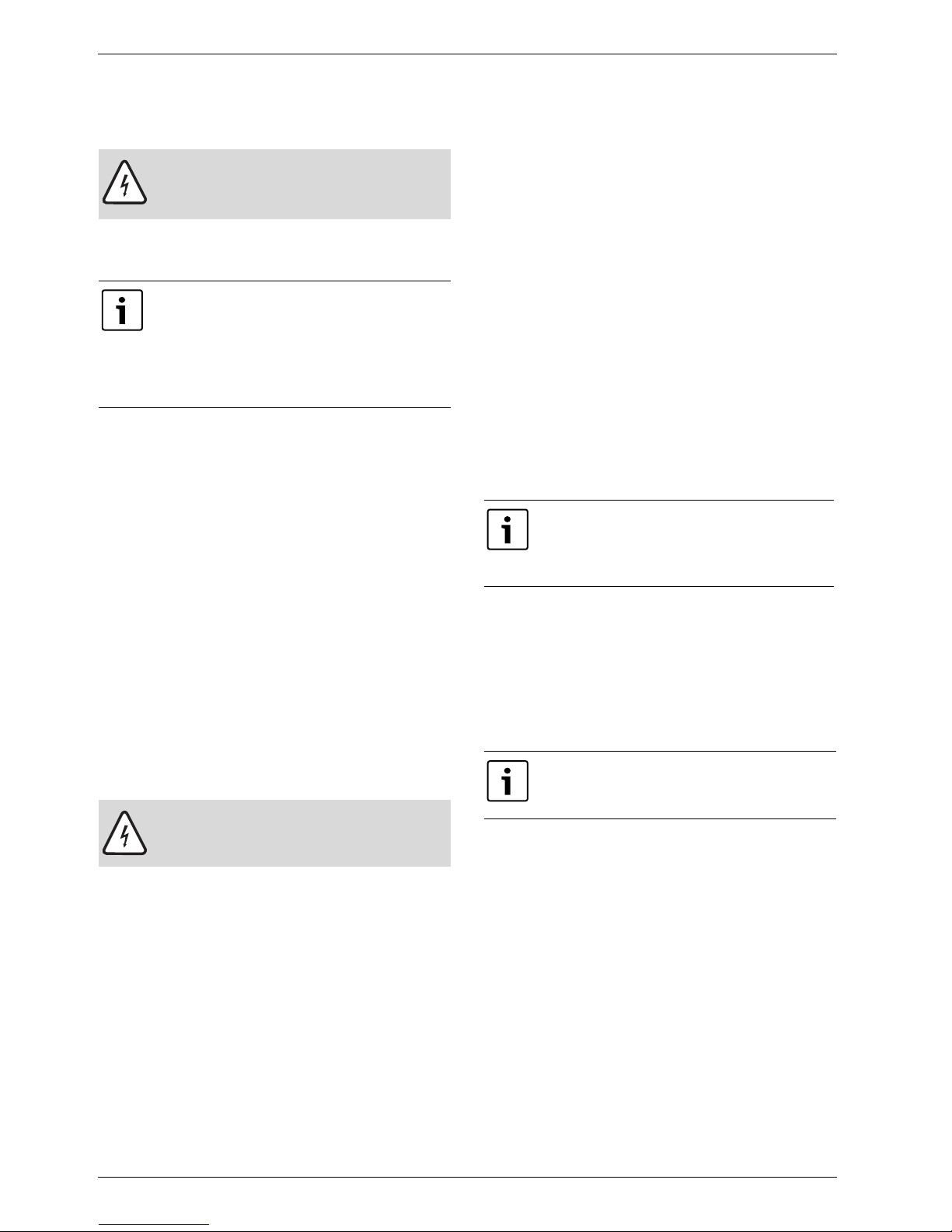
B Turn the valves on the filling station to filling position
and fill the circuit with collector circuit fluid
( Figure 19).
Fig. 19 Filling unit in filling position
Double U pipes, each of which consists of
two descending and two ascending pipes,
are most often used as a rock collector.
6720614967-32.1I
Repeat the following steps for each circuit.
One circuit at a time is filled with collector
circuit fluid. Keep the valves closed in the
other loops during the process.
6720614967-35.1I
Page 29
Installation
6 720 645 504 (2011/04) en
29
B When the fluid level has fallen to 25% in the filling
station, the pump should be stopped and more
collector circuit fluid should be filled and mixed.
B When the circuit is full and air no longer comes from
the return pipe, the pump should be run again for at
least 60 minutes (the fluid should be clear and should
not contain any bubbles).
B The circuit must be pressurized when venting is
complete. Turn the valves on the filling unit to
pressure increase position and pressurize the circuit
to 2.5 to 3 bar ( Figure 20).
Fig. 20 Filling unit in pressure increase position
B Turn the valves of the filling unit to normal position (
Figure 21) and turn off the pump on the filling station.
Fig. 21 Filling unit in normal position
B Disconnect the hoses and insulate the filling unit.
If other equipment is used, the following is required,
among other things:
• A clean container with capacity for the amount of
collector circuit fluid that is required
• An additional container for collection of contaminated
collector circuit fluid
• Submerged pump with filter, flow capacity of min.
6m
3
/h, pressure height of 60 to 80 m
• Two hoses, Ø 25 mm
6720614967-34.1I
6720614967-32.1I
Page 30
Electrical connections
6 720 645 504 (2011/04) en
30
11 Electrical connections
All regulation, control and safety devices on the heat
pump are connected and checked upon delivery.
B According to the applicable regulations for 400 V/
50 Hz connection, a H05VV-... type 5-core cable must
be used as a minimum. Select cable area and cable
type that corresponds to the relevant fuse rating
( Chapter 8.4) and routing method.
B Observe protection measures acc. to VDE regulations
0100 and special regulations of the local power
supply utility.
B Connect the heat pump to the electric box connection
strip according to BS EN 60335 part 1 and via a switch
with a minimum contact distance of 3 mm (e.g. fuses,
LS switch). Other consumers must not be connected.
B Follow the relevant wiring diagram when connecting
an earth breaker. Only connect components that are
approved for each market.
B Observe the colour coding when replacing circuit
boards.
11.1 Connecting the heat pump
B Remove the front panel ( page 26).
B Remove the electric box cover.
B Route the connection cables to the electric box
through the cable gland in the roof plate of the heat
pump.
B Connect the cables according to the wiring diagram.
B Reinstall the electric box cover and the front panel of
the heat pump.
11.2 Phase guard
A phase guard is mounted and connected to the heat
pump in order to monitor the phase sequence to the
compressors during installation ( Figure 33 and 34).
There are three indicator lamps on the phase guard.
When the heat pump is started the first time the
uppermost lamp lights up yellow and the bottom lamp
green. The lamp in the middle flashes red if there is a
phase sequence error and the alarm Phase error E2x.B1
( Chapter 17.9.11) is displayed. If so, change the
phase sequence. The lamp is not lit at correct phase
sequence.
The phase guard also trips on too high or too low
voltage. The lamp in the middle lights red and the alarm
Phase error E2x.B1 ( Chapter 17.9.11) is displayed.
11.3 Screed drying
Screed drying must take place with continuous access to
current. When screed drying is used, the electric
connection should therefore be made in the standard
way, see ( Chapter 11.4).
On completion of screed drying, the EVU signal can be
connected (Chapter 11.4). Enable the EVU signal
according to the settings under menu External control.
The screed drying process is described in
( Chapter 16.6.9).
DANGER: Risk of electric shock!
B Switch off the main power supply before
starting work on the electrical part.
The heat pump's electrical connections
must be able to be disabled safely.
B Install a separate safety switch that cuts
all current to the heat pump. A safety
switch for each supply is required for
separate power supplies.
CAUTION: Never grasp a circuit board
without wearing a ground-connected
bracelet ( Chapter 5.10).
The heat pump alone can not produce
enough heating for screed drying. We
recommend using building drying
equipment.
EVU means a special electrical connection
used primarily in countries like Germany and
Austria.
Page 31

Electrical connections
6 720 645 504 (2011/04) en
31
11.4 Electrical connection wiring diagram
11.4.1 Overview of connection between distribution box and heat pump (HC 22 - 33)
Fig. 22 Overview of connection between distribution box and heat pump
1 Power supply to the distribution box
2 Power meter for heat pump, low tariff
3 Tariff control
4 Power meter for the property, 1-phase high tariff
5 Compressor 1 and 2
6 Control unit, E21.G2, E22.G2, EVU, external pumps
7 Collector circuit pump E21.G3, E22.G3
EVU Property's distribution box
EWP Heat pump
*) Strap which is removed in the event of separate power supply
D External power meter
1
2
3
4
5 6
7
EVU
EWP
6 720 618 981-11.1I
EVU means a special electrical connection
used primarily in countries like Germany and
Austria.
Page 32

Electrical connections
6 720 645 504 (2011/04) en
32
11.4.2 Overview of electric box (HC 22 - 33)
Fig. 23 Overview of electric box
1 Electric box heat pump HC 22
2 Electric box heat pump HC 33
E21.F11 Motor cut-out compressor E21
E22.F11 Motor cut-out compressor E22
E21.B1 Phase guard for E21 and E22
E21.F1 Miniature circuit-breaker heat pump
E21.F3 Miniature circuit-breaker E21.G3
E22.F3 Miniature circuit-breaker E22.G3
K1 Contactor compressor E21
K2 Contactor compressor E22
K4 Relay E22.K4
Q1.1/Q1.2 Soft starter E21
Q2.1/Q2.2 Soft starter E22
X1 Terminal block
E21.V1-2 EMC filter
BAS Circuit board
PGB Circuit board
XB1 Circuit board
PEL Low-voltage external terminal board
PHV Terminal board 230 V
6 720 616 938-3.1I
1 2
Page 33

Electrical connections
6 720 645 504 (2011/04) en
33
11.4.3 Overview of circuit boards
Fig. 24 Overview of circuit boards and factory-assembled cables
LCD Display board
BAS Circuit board
PGB Circuit board
XB1 Circuit board
PEL Low-voltage external terminal board
PHV Terminal board 230V
PIL Low-voltage internal terminal board
6 720 616 938-6.1I
Page 34

Electrical connections
6 720 645 504 (2011/04) en
34
11.4.4 Power supply of EVU signal
EVU relay (no. 4, A1, A2, no. 2 Figure 25) with 3 main
contacts and 1 auxiliary contact must be dimensioned in
accordance with the heat pump's fuse rating. The relay
is provided by an electrical fitter or a power company.
Control requires a potential-free contact signal on the
external input (1 / C Figure 25). External input
connected = EVU block active.
During the blocked period, the energy supply cut-off
symbol is displayed in the menu display.
Fig. 25 Blocked period enabled
1 Power meter
2 Tariff control
3 Control unit heat pump
4 Low-tariff
EVU means a special electrical connection
used primarily in countries like Germany and
Austria.
Complete screed drying before connection
of the EVU signal.
B Activate the energy supply cut-off in the
control unit under menu External control
(Chapter 16.5) after drying and
connection of the EVU signal.
2
1
3
4
6 720 614 366-50.2I
Time difference
B Ensure a maximum time difference of 5
seconds between current control and
EVU signal control.
Page 35

Electrical connections
6 720 645 504 (2011/04) en
35
11.4.5 Power supply (HC 22 - 33)
Fig. 26
1 X1 The terminal block in the heat pump
2 The PEL card where the EVU signal is connected
3 PE (protective earth)
Standard design without EVU
The terminal blocks are strapped at the factory to a
common power supply. Connected to PE, 1N, 1L1, 1L2
and 1L3.
Fig. 27 Standard design
1 Supply, Heat pump
Alternative A
The power supply can also be connected as low tariff
from the EVU control unit. During a cut-off period, the
cont rol un it i s sup plie d wit h 1-p hase , L1, high tar iff. They
are connected to PE, 3N and 2L1. Signal from the control
unit via EVU control is connected to terminal blocks 1
and C on the PEL card. During a cut-off period, the
contact is closed. The terminal straps between 1N-3N
and 1L1-2L1 are removed.
Fig. 28 Connections Alternative A
1 Supply, 1-phase L1 to control unit by EVU
2 Supply, heat pump
2
1
3
6720614967-21.1I
EVU means a special electrical connection
used primarily in countries like Germany and
Austria.
1
6 720 616 938-7.1I
6 720 616 938-8.1I
2
1
Page 36

Electrical connections
6 720 645 504 (2011/04) en
36
Alternative B
If the collector circuit pumps should be supplied
separately, they are connected to PE, 2N, 2L2 and 2L3.
Remove all terminal straps.
Fig. 29 Connection alternative B
1 Supply 1-phase L1 to control unit by EVU
2 Supply, heat pump
3 Supply, collector circuit pumps
11.5 External connections
All external connections are made on terminal board PEL
(low current) and PHV (high current):
B High and low current cables should be routed
separately in order to avoid interference on the
sensors (minimum distance of 100 mm).
B Use the following cable area when extending a
temperature sensor cable:
– Up to 20 m long cable: 0.75 to 1.50 mm
2
– Up to 30 m long cable: 1.0 to 1.50 mm
2
6 720 616 938-9.1I
2
3
1
Page 37

Electrical connections
6 720 645 504 (2011/04) en
37
11.6 Other wiring diagrams
11.6.1 Explanations
+ = Open, – = Close
E11 Circuit 1
E10.T2 Outdoor sensor
E11.G1 Circulation pump, heating system
E11.P2 General alarm
E11.S11 External set point value
E11.T1 Flow sensor
E11.TT.P1 Alarm lamp, room sensor
E11.TT.T5 Room sensor, circuit 1
Tab. 18 E 11 Circuit 1
E12 Circuit 2
E12.B11 External input, circuit 2
E12.G1 Circulation pump
E12.TM Dew point sensor
E12.TM.TM5 Room temperature sensor
E12.TM.TM1 Humidity sensor
E12.T1 Flow sensor
E12.TT.P1 Alarm lamp, room sensor
E12.TT.T5 Room temperature sensor
E12.Q11 Mixing valve
Tab. 19 E12 Circuit 2
E21 Compressor 1 (Step 1)
B1 Alarm phase guard (for E21 and E22)
B11 External input 1
B12 External input 2
F3 Circuit breaker, collector circuit pump
F11 Motor cut-out compressor
F12 Motor cut-out collector circuit pump
F51 Fuse 6.3A
F52 Fuse 250mA
G2 Heat carrier pump
G3 Collector circuit pump
K1 Contactor
RHP High pressure switch
RLP Low pressure switch
Q1.1 Soft starter HC 22
Q1.2 Soft starter HC 33
Q21 3-way valve
T6 Hot gas sensor (compressor)
T8 Sensor heat transfer fluid out
T9 Sensor heat transfer fluid in
T10 Sensor collector circuit in
T11 Sensor collector circuit out
E21.B1 Alarm phase guard (for E21 and E22)
E21.E1 Compressor E21
E21.F1 Miniature circuit-breaker heat pump
E21.F3 Miniature circuit-breaker E21.G3
E21.F11 Motor cut-out compressor E21
E21.V1 EMC filter
E21.V2 EMC filter
Tab. 20 E21 Compressor 1 (Step 1)
E22 Compressor 2 (Step 2)
B11 External input 1
B12 External input 2
F3 Circuit breaker, collector circuit pump
F11 Motor cut-out compressor
F12 Motor cut-out collector circuit pump
F13 Compressor cut-out
F51 Fuse 6.3A
G2 Heat carrier pump
G3 Collector circuit pump
K2 Contactor
K3 Contactor, collector circuit pump
RHP High pressure switch
RLP Low pressure switch
Q2.1 Soft starter HC 22
Q2.2 Soft starter HC 33
Q21 3-way valve
T6 Hot gas sensor (compressor)
T8 Sensor heat transfer fluid out
T9 Sensor heat transfer fluid in
T10 Sensor collector circuit in
T11 Sensor collector circuit out
E22.E1 Compressor
E22.F3 Circuit breaker, collector circuit pump
E22.F11 Motor cut-out compressor
E22.F12 Motor cut-out collector circuit pump
E22.F13 Compressor cut-out
E22.V1 EMC filter
Tab. 21 E22 Compressor 2 (Step 2)
E41 and E42 Hot water heater 1 and 2
E41.E1.E1 Hot water electric heater
E41.E1.F21 Overheat protection, hot water electric
heater
E41.F31 Protective anode
E41.G6 Circulation pump hot water
E41.Q1 Mixing valve, hot water
E41.T1 Hot water flow
E41.T3 Sensor, hot water
E42.T3 Sensor, hot water
Tab. 22 E41 and E42 Hot water heater 1 and 2
E71 Additional heat
E71.E1.E1 Allow additional heat
E71.E1.Q71 Additional heat mixing valve
E71.E1.E1.F21 Alarm, additional heat
Tab. 23 E71 Additional heat
Page 38

Electrical connections
6 720 645 504 (2011/04) en
38
11.6.2 Internal wiring diagram
Fig. 30 Internal wiring diagram
6 720 616 938-13.1I
Page 39

Electrical connections
6 720 645 504 (2011/04) en
39
11.6.3 Wiring diagram E21, high current
Fig. 31 Wiring diagram E21, high current
Solid line = factory connected. Dotted line = connected at installation.
6 720 616 938-15.1I
Page 40

Electrical connections
6 720 645 504 (2011/04) en
40
11.6.4 Wiring diagram E22, high current
Fig. 32 Wiring diagram E22, high current
Solid line = factory connected. Dotted line = connected at installation.
6 720 616 938-16.1I
E22.Q21
Page 41

Electrical connections
6 720 645 504 (2011/04) en
41
11.6.5 Wiring diagram E21, low current
Fig. 33 Wiring diagram E21, low current
Solid line = factory connected. Dotted line = connected at installation.
6 720 616 938-18.1I
Page 42

Electrical connections
6 720 645 504 (2011/04) en
42
11.6.6 Wiring diagram E22, low current
Fig. 34 Wiring diagram E22, low current
Solid line = factory connected. Dotted line = connected at installation.
6 720 616 938-19.1I
Page 43

Electrical connections
6 720 645 504 (2011/04) en
43
11.6.7 External connections E21
Fig. 35 External connections E21
Solid line = factory connected. Dotted line = connected at installation.
6 720 616 938-20.1I
Page 44

Electrical connections
6 720 645 504 (2011/04) en
44
11.6.8 External connections E22
Fig. 36 External connections E22
Solid line = factory connected. Dotted line = connected at installation.
6 720 616 938-21.1I
E22.Q21
Page 45

Electrical connections
6 720 645 504 (2011/04) en
45
11.7 Connection of additional heat alarm
Fig. 37 Alarm, additional heat
E71 Additional heat
E71.E1.E1.F21 Alarm, additional heat
A1, A2, 11, 14 Relay
10, C Terminal blocks, PEL board
B Use an intermediate relay on connection of additional
heat alarm E71.E1.E1.F21 to the low-voltage board
( Figure 33) when the alarm signal of the additional
heat is 230V.
11.8 Connection of domestic hot water
electric heater
Fig. 38 Connection, hot water electric heater
PHV1 Circuit board in the control unit
A1,A2, 1-6 Contactor
E41.E1.E1 Hot water electric heater
E41.E1.F21 Overheat protection, hot water electric heater
The electric heater is supplied with its own 3-phase
voltage from the distribution box. Control is exercised
from the control unit via the contactor.
The distribution box supplies the control unit with 1phase 230V on PHV1, terminal board 74.
The outgoing signal to the contactor for control of the
electric heater is on PHV1, terminal board 73.
Connect the alarm signal from phase L1 to PHV1,
terminal board, after the overheat protection. When the
overheat protection is triggered, the voltage on terminal
block 72 disappears and alarm is given in the display.
Acknowledge Hot water electric heater under
Additional heat \ Hot water electric heater.
6 720 616 938-40.1I
6 720 616 938-27.2I
Page 46

Electrical connections
6 720 645 504 (2011/04) en
46
11.9 Connection of circulation pump
E41.E1.G1
Fig. 39 Connection of circulation pump E41.E1.G1
The circulation pump is part of the system solution with
mixed additional heat ( Chapter 8.2.3)
The circulation pump has its own voltage feed from the
distribution box. The pump is controlled from the
control unit. Incoming voltage feed is connected to
terminal block 72 and 74 on PHV1, outgoing voltage feed
on terminal block 73.
The maximum load is 2.6A when cos ϕ = 0.4. For
example, Wilo Star-Z 15 can be used.
11.10 Connection of low energy pump
E11.G1
Fig. 40 Connection of low energy pump E11.G1
When a low energy circulation pump is connected in the
heating circuit an intermediate relay must be used for
pump control.
The relay is connected to terminal blocks 62 and N on
the PHV board (output for E11.G1).
E11.G1 is powered externally.
6 720 616 938-28.1I
6 720 645 810-01.1I
Page 47

Control panel
6 720 645 504 (2011/04) en
47
12 Control panel
Settings for the control of the heat pump are made with
the control unit's control panel, which also provides
information about current status.
12.1 Panel overview
Fig. 41 Control panel
1 On/Off button
2 Mode button
3 Info button
4 Menu dial
5 Status lamp
6 Return button
7 Menu button
8 Menu display
12.2 On/Off button
Use the On/Off button to switch the heat pump on and
off.
12.3 Status lamp
12.4 Menu display
Use the menu display in order to:
• View information from the heat pump.
• View available menus.
• Change set values.
12.5 Menu button and menu dial
Use to get from Initial menu to the menus. Use the
menu dial in order to:
• Navigate the menus and get to the setting displays.
– Turn the dial to see more menus on the same level
or change a set value.
– Press the dial to change to a lower menu level or
save a change.
12.6 Return button
Use to:
• Go back to the previous menu level.
• Leave a setting display without changing the set
value.
12.7 Mode button
Use to change type of operation.
12.8 Info button
Use to see information from the control unit about
operating mode, temperature, program version, etc.
The lamp lights green. The heat pump is running.
The lamp flashes red. There is an alarm which
has not been acknowledged
The lamp lights red. The alarm has been
acknowledged but the
alarm cause remains
Lamp flashes slowly
green, menu window
not lit.
The heat pump is in standby mode
1)
.
1) Stand-by means that the heat pump is running but no
heating or hot water demand exists.
The lamp and menu
display not lit.
No voltage to control unit.
Tab. 24 Lamp functions
menu
mode
i
6 720 641 855-08.1I
5
6
2
8
1
7
4
3
The controller language can be changed
with the -key.
B Press the button in the standard
display for at least 5 s, then select the
required language.
Page 48

Start up
6 720 645 504 (2011/04) en
48
13 Start up
The first time the heat pump is started, a number of
settings are displayed automatically so as to facilitate
putting it in operation.
Before this stage, the heat pump should be installed in
accordance with the previous sections ( Chapter 10,
Chapter 11). Collector circuits, heating circuits and
hot water circuits should be filled and vented.
The settings are also available under ordinary installer
menus.
Language, Country and Operating mode
B Select language for the menus of the control unit
( Chapter 16.9).
B Select Country ( Chapter 16.9).
B Select operating mode (L/W + mixed additional heat)
( Chapter 6.4, Chapter 16.6.1).
Start-up
Review and adjust, as required, the functions below. See
the references for description of the functions.
B Set Heat pump capacity according to the details on
the type plate ( Chapter 5.3 and 16.6.2).
B Set Hot water production for each heat pump
(compressor) ( Chapter 16.2).
B Set Minimum outdoor temperature ( Chapter
16.1.1).
B Set Groundwater if it is installed.
B Set Circuit 1 Heating\ Type of heating system (
Chapter 16.1.2).
B Set Circuit 1 Cooling (if Cooling has been installed,
accessory), see the accessory documentation.
B Set Circuit 2, 3... ( Chapter 16.1.3).
– Mixing valve mode
– Type of heating system
– Mixing valve running time
B Select alternative in Protective anode installed
( Chapter 16.2).
B Set values for Mixed additional heat
( Chapter 16.7).
– Mixing valve running time
– Delay mixing valve control after additional heat
start
– Acknowledge Hot water electric heater if such
exists ( Chapter 16.7).
B Set Date ( Chapter 16.9).
B Set Time ( Chapter 16.9).
B Start-up completed, Yes/No.
The start-up menus will be available until Yes is
entered.
After the start-up menus, the Initial menu is shown in the
display. All customer functions are accessible from this
menu, whereas the installer menus are accessible only
after change of access level.
Fig. 42 Initial menu
Only functions which are identified by the
control unit are displayed in the initial
menu.
The start-up menus are available until Yes is
entered in Start-up completed.
B Read the complete menus before start-
up.
B A selection must be made in Protective
anode installed.
With the -button, reinstate the
selection that applied to Language, Country
or Operating mode prior to or during Start-
up.
The selected system solution would
normally require a review of more settings
than the ones in the start-up.
Under Protective anode installed make the
appropriate selection to prevent
unnecessary alarm messages.
6 720 614 789-01.1I
Page 49

Installer menus
6 720 645 504 (2011/04) en
49
14 Installer menus
14.1 Access to the functions on Installer
level
A four digit access code is required to switch from
Customer level to Installer level in the menus. The
access code is the present date given as two digits for
the month and two digits for the date (for example
0920).
B Go to Access level under Menu at Customer level.
B Enter the four digit access code using the menu dial.
Press the menu dial after setting each digit.
Access = Installer shown in the menu window.
B Turn the menu dial to see the menus in the top level.
All functions at Customer level and Installer level can
now be reached.
The control unit returns automatically to Customer level:
• After 20 min (adjustable value, Chapter 16.6.1).
14.2 Compressor fast restart
During commissioning, manual operation, etc., you may
need to quickly restart the compressor without waiting
for the restart timer (10 min).
B Press for 5s in an optional installer menu (not a
setting display).
The compressor starts after 20s.
14.3 Temperature sensor
The control unit controls the production of heat, hot
water, etc., after signals from a great number of
temperature sensors. Most signals that can appear in
the display are listed here.
E21 = Compressor 1 / Heat pump 1
E22 = Compressor 2 / Heat pump 2
Sensors for options
The control unit recognizes which sensors are installed
and acknowledges them automatically. An accessory
sensor can be deacknowledged manually in the control
unit. This makes it possible to remove the sensor from
the control unit if it is not used.
Complete component names are displayed
in the control unit only when needed. If, for
example, you are in a menu which refers
only to circuit 2, the sensor names are
indicated without E12. before the sensor
name.
The complete name is always presented in
alarm information so as to facilitate
troubleshooting. Full names can also be
found on drawings and in system solutions.
T1
E11.T1
Flow, circuit 1
T2
E10.T2
Outdoor
T5
E11.TT.T5
Room, circuit 1 (accessory)
T6
E21.T6
Hot gas
T8
E21.T8
Heat transfer fluid out
T9
E21.T9
Heat transfer fluid in
T10
E21.T10
Collector circuit in
T11
E21.T11
Collector circuit out
T1
E12.T1
Flow, circuit 2 (if circuit 2 is used)
T5
E12.TT.T5
Room, circuit 2 (accessory)
Tab. 25 Temperature sensors
E22.T6 Hot gas
E22.T8 Heat transfer fluid out
E22.T9 Heat transfer fluid in
E22.T10 Collector circuit in
E22.T11 Collector circuit out
Tab. 26 Sensors, heat pump 2
E41.T3
E42.T3
Hot water
Tab. 27 Hot water sensors
E13.T1 Flow, circuit 3
E13.TT.T5 Room, circuit 3 (accessory)
E14.T1 Flow, circuit 4
E14.TT.T5 Room, circuit 4 (accessory)
Tab. 28 Sensors, circuit 3, 4
Page 50

Menu overview
6 720 645 504 (2011/04) en
50
15 Menu overview
The top menu level for installers is:
• Room temperature
• Hot water
• Holiday
• Timers
• External control
• Installer
• Additional heat
• Safety functions
• General
• Alarms
• Access level
• Return to factory settings
• Program version
Access level 0 = Customer
Access level 1 = Installer
HP x = Heat pump 1 or 2 / Compressor 1 or 2
Room temperature
Access
level
General Summer/winter operation Circuit 1, Circuit 2, 3...
> Winter operation
> Outdoor temperature limit for change
over
> Delay before change over to winter
operation
> Delay before change over to summer
operation
> Direct start limit for winter operation
0
0
1
1
1
Shut down protection during change over from
hot water to heating
1
Minimum outdoor temperature
1
Tab. 29 Room temperature menus
Page 51

Menu overview
6 720 645 504 (2011/04) en
51
Circuit 1 Heating External set point value 1
Use temperature from circuit with highest temperature
1
Type of heating system
1
Highest permitted flow temperature T1
1
Lowest permitted flow temperature T1
1
Heat curve
0
Heat curve hysteresis heat pump x
Maximum
Minimum
Time factor
1
1
1
Room sensor
Room temperature influence (if installed)
Knob's operating range (CAN-BUS)
Acknowledge room sensor
0
0
1
Room temperature program
Active program
View/edit active program
Room temperature normal
Temperature increase/decrease (no
room sensor)
Setting temp. increase/decrease (no
room sensor)
> Limit value for left or right end point
> Change when much colder/warmer
> Change when colder/warmer
Room temperature influence (no room
sensor)
Room temperature exception
Copy to all heating circuits
0
0
0
0
1
1
1
1
0
0
0
Air handling unit in circuit
1
Circuit 2, 3... Mixing valve mode 1
Type of heating system
1
Highest permitted flow temperature T1
1
Lowest permitted flow temperature T1
1
Heat curve
0
Room sensor
Room temperature influence (if installed)
Acknowledge room sensor
0
1
Room temperature program
Som Circuit 1 Heatingminus Copy to all
heating circuits
0, 1
Regulator settings
P constant
I constant
D constant
Minimum PID signal
Maximum PID signal
Mixing valve running time
Mixing valve fully closed
Mixing valve start closing
Connected to output type
1
1
1
1
1
1
1
1
1
Air handling unit in circuit
1
Room temperature
Access
level
Tab. 29 Room temperature menus
Page 52

Menu overview
6 720 645 504 (2011/04) en
52
Hot water
Access
level
Extra hot water Extra hot water duration
Extra hot water stop temperature
0
0
Hot water peak Day of the week
Interval in weeks
Start time
Stop temperature
Maximum time
Time for warm-keeping
0
0
0
1
1
1
Hot water program Active program
View/edit active program
0
0
Hot water mode 0
Hot water settings heat pump x Hot water production
Start temperature T3 economy mode
Stop temperature T8 economy mode
Start temperature T3 comfort mode
Stop temperature T8 comfort mode
1
1
1
1
1
Block heating during hot water demand 0
Maximum temperature difference circuit 1 1
Hot water circulation Hot water circulation pump active
Time settings
1
1
Protective anode installed 1
Acknowledge hot water sensor E41.T3 1
Acknowledge hot water sensor E42.T3 1
Tab. 30 Hot water menus
Holiday
Access
level
Circuit 1 and hot water Activate holiday function
Start date
Stop date
Room temperature
Copy to all heating circuits
Block hot water production
0
0
0
0
0
0
Circuit 2, 3... Activate holiday function
Start date
Stop date
Room temperature
0
0
0
0
Tab. 31 Holiday menus
Timers
Access
level
Extra hot water 0
Hot water peak time for warmkeeping
1
Alarm mode delay 0
Party mode 0
Tab. 32 Timers
Page 53

Menu overview
6 720 645 504 (2011/04) en
53
Heat pump x timers Compressor start delay 0
Compressor start delay groundwater
1
G2 heat carrier pump stop delay
1
Block low pressure switch
1
Additional heat timers Additional heat start delay 0
Delay mixing valve control after additional heat start
0
Additional heat program activation delay
after low outdoor temperature
1
Additional heat start delay after high outdoor temperature
1
Delay before change over to summer operation
1
Delay before change over to winter operation
1
Shut down protection during
change over from hot water to
heating
1
Heating start delay 1
Heating stop delay 1
External control
Access
level
Heat pump x External input 1, 2 Invert input 1
Block compressor x 0
Block additional heat 0
Block heating at tripped underfloor temperature limiter 1
Block heating 0
Room temperature 0
Block hot water production 0
Start collector circuit pump 1
Alarm at low pressure in collector circuit 1
Alarm groundwater circuit 1
External input circuit 2, 3... Invert input 1
Block heating at tripped underfloor temperature limiter 1
Block heating 0
Room temperature 0
Tab. 33 External control
Installer
Access
level
General Anti-seizure mode Day of the week
Start time
Minimum outdoor temperature
1
1
1
Highest permitted flow temperature T1
1
Operating mode
1
Groundwater
Groundwater
Compressor start delay groundwater
1
1
Display light switch off delay
1
Time for reset of access level
1
Heat pump capacity 1
Connected I/O boards All boards and current version are dis-
played, if relevant
1
Tab. 34 Installer menus
Timers
Access
level
Tab. 32 Timers
Page 54

Menu overview
6 720 645 504 (2011/04) en
54
Operating times and consumptions
The total operating time for the compressor and additional heat (active connection). It can also make short term
measurements.
1
Temperatures All connected/acknowledged sensors
present values. The opportunity to correct the sensors is also given
1
Inputs The status of all connected inputs is dis-
played here. Pressure switches and
motor cut-outs are shown for each heat
pump
1
Outputs All components can be manually oper-
ated individually here to check function
1
Circulation pumps Operation alternative heating circuit
pump G1
1
Operation alternative heat carrier pump
G2
1
Operation alternative collector circuit
pump G3
1
Screed drying Activate 1
Current program step
1
Remaining time for current step
1
Heat source
1
Program settings
Flow temperature increase per heating
step
Number of days per heating step
Maximum flow temperature
Number of days with maximum temperature
Flow temperature decrease per cooling
step
Number of days per cooling step
1
1
1
1
1
1
Installer
Access
level
Tab. 34 Installer menus
Page 55

Menu overview
6 720 645 504 (2011/04) en
55
Additional heat
Access
level
Additional heat general Start delay 1
Allow additional heat timer during energy supply
cut-off
1
Additional heat only
1
Ramp time when additional heat only
1
Block additional heat
1
Maximum outdoor temperature for additional
heat
1
Additional heat set point value E11.T1 offset
1
Mixed additional heat Delay mixing valve control after additional heat
start
1
Regulator settings
P constant
I constant
D constant
Minimum PID signal
Maximum PID signal
Mixing valve running time
Connected to output type
1
1
1
1
1
1
1
Hot water electric heater Acknowledge hot water additional heat 1
Temperature change
1
Hysteresis
1
Additional heat program Activate program 1
View/edit active program
1
Outdoor temperature limit for deactivation of
time control
1
Tab. 35 Additional heat menus
Safety functions
Access
level
Setting collector circuit in T10 Lowest permitted temperature E21.T10 1
Lowest permitted temperature E22.T10
1
Hysteresis alarm reset
1
Number of warnings before alarm
1
Setting collector circuit out T11 Lowest permitted temperature E21.T11 1
Lowest permitted temperature E22.T11
1
Hysteresis alarm reset
1
Number of warnings before alarm
1
Tab. 36 Safety functions menus
General
Access
level
Set date 0
Set time 0
Summer/winter time 0
Display backlight intensity 0
Language 0
Country 1
Tab. 37 General menus
Page 56

Menu overview
6 720 645 504 (2011/04) en
56
Alarms
Accessle
vel
Alarm log 0
Delete alarm log 0
Alarm history 1
Alarm indication Alarm buzzer signal Interval
Blocking time
0
0
Alarm indication control unit
Block alarm buzzer 0
Alarm indication room sensor
Block alarm buzzer
Block alarm indicator lamp
0
0
General alarm level
Alarms and warnings 1
Tab. 38 Alarm menus
Access level
Access
level
Access level 0, 1
Tab. 39 Access level menu
Return to factory settings
Access
level
Return to factory settings 0, 1
Tab. 40 Return to factory settings menu
Page 57

Settings
6 720 645 504 (2011/04) en
57
16 Settings
16.1 Room temperature
Press the button in the standard display to open the
main menu. Select Room temperature to adjust the
heating.
The following options are available under Room
temperature:
• General
• Circuit 1 Heating
• Circuit 2, 3...
16.1.1 General
Here are:
• Summer/winter operation
• Shut down protection during change over from hot
water to heating
• Minimum outdoor temperature
> Summer/winter operation
>> Circuit 1
>>> Winter operation
If On is selected, the heat pump is constantly in winter
operation and heat and hot water are always produced.
Off signifies constant summer operation; only hot water
is produced. Automatic signifies change-over at the set
outdoor temperature.
>>> Outdoor temperature limit for change over
The menu is displayed only if Automatic has been
selected in Winter operation.
>>> Delay before change over to winter operation
>> Delay before change over to summer operation
>>> Direct start limit for winter operation
When the Use temperature from circuit with highest
temperature function for Circuit 1 is used Circuit 2, 3...
are displayed under Summer/winter operation. The
same settings as for Circuit 1 can be made for each
circuit. The factory settings are the same as for Circuit 1.
Factory setting Automatic
Alternative On/Automatic/Off
Tab. 41 Summer/winter operation
Factory setting 18 °C
Lowest value 5 °C
Highest value 35 °C
Tab. 42 Change over temperature
Factory setting 4h
Lowest value 1h
Highest value 48h
Tab. 43 Delay before change over to winter operation
Factory setting 4h
Lowest value 1h
Highest value 48h
Tab. 44 Delay before change over to summer operation
Factory setting 13 °C
Lowest value 5 °C
Highest value 17 °C
Tab. 45 Direct start limit
In the event of change over between winter
and summer operation and vice versa, there
is a certain delay to prevent constant
starting and stopping of the compressor
when the outdoor temperature oscillates
around the temperature limit.
Below the direct start limit, the control unit
changes over to winter operation without
delay.
Circuit 1 is never allowed to switch over to
summer operation for as long as any circuit
is in winter operation.
Page 58

Settings
6 720 645 504 (2011/04) en
58
> Shut down protection during change over from hot
water to heating
B Set how long it should take before a heating demand
may be deactivated after hot water production. This
ensures that the hot water amount that goes out into
the heating circuit after production of hot water does
not become a reason for incorrect deactivation of a
heating demand.
> Minimum outdoor temperature
B Set the minimum outdoor temperature for the heat
curve.
16.1.2 Circuit 1 Heating
Here are:
• External set point value
• Use temperature from circuit with highest
temperature
• Type of heating system
• Highest permitted flow temperature T1
• Lowest permitted flow temperature T1
• Heat curve
• Heat curve hysteresis heat pump x
• Room sensor
• Room temperature program
> External set point value
B Change to Yes if an external signal 0-10V should
control the flow temperature (fixed set point value).
1V= 10 °C, 10V = 80 °C (linear function).
> Use temperature from circuit with highest
temperature
B Change to Yes if the set point value for Circuit 1
should be the highest of Circuit x's set point values.
Only circuits in Winter operation are included.
This function means that the set point value for
Circuit 1 is always adapted to current need.
In the event of Yes, Summer/winter operation can be
set also for the mixed circuits.
The function is used when Circuit 1 only consists of a
buffer tank.
> Type of heating system
B Select type of heating system, Radiator or
Underfloor.
B Change to Radiator at Yes in Use temperature from
circuit with highest temperature.
B Change to Radiator at External heat source (solar,
firewood).
The factory settings for the Radiator have a curve value
(flow temperature) of 22 °C at 20 °C an outdoor
temperature, 37.4 °C at –2.5 °C and 60 °C at -35 °C at
an outdoor temperature (the high point of the curve).
The factory settings for the Underfloor have a curve
value (flow temperature) of 22 °C at 20 °C outdoor
temperature, 27.2 °C at -2.5°C and 35 °C at -35 °C
outdoor temperature.
At a temperature higher than 20 °C, the same curve
value applies as for 20 °C.
Factory setting 180s
Lowest value 0s
Highest value 600s
Tab. 46 Shut down protection during change over to hot
water
Factory setting -35,0 °C
Lowest value -35,0 °C
Highest value -10,0 °C
Tab. 47 Lowest outdoor temperature
Factory setting No
Alternative Yes/No
Tab. 48 External set point value
Ensure that the incoming signal does not
generate higher flow temperature than what
Circuit 1 withstands.
All safety functions for the heating system
must be handled by the external equipment.
Factory setting No
Alternative Yes/No
Tab. 49 Temperature from circuit with highest
temperature
Factory setting Underfloor
Alternative Radiator/Underfloor
Tab. 50 Type of heating system
Page 59

Settings
6 720 645 504 (2011/04) en
59
> Highest permitted flow temperature T1
B Change to 100 °C at External heat source.
1)
The value that is set in Lowest permitted flow
temperature T1.
> Lowest permitted flow temperature T1
B Set the highest and lowest permitted temperature for
T1. Ensure that the value corresponds with the
selected curve and possible curve adjustments.
B Check also that the highest temperature T1 with
Underfloor does not exceed the permitted value for
the type of floor used.
> Heat curve
The heat curve constitutes the basis for the control
unit's control of the temperature on the heating water to
the circuit and indicates how high it needs to be in
relation to the outdoor temperature. The control unit
increases the temperature of the heating water when the
outdoor temperature drops. The temperature of the
heating water out to the circuit, i.e. the flow temperature
is measured by sensor T1 for circuit 1 (full name E11.T1)
and sensor T1 for circuit 2 (full name E12.T1).
Each circuit is controlled by its own heat curve. In Type
of heating system, a curve can be selected for Radiator
or Underfloor. The curve for Underfloor has lower
values because the floors do not require high
temperatures.
Fig. 43 Radiator
The figure indicates the factory setting curve for a
radiator circuit. At -2.5 °C the flow set point is 37.4 °C.
Fig. 44 Underfloor heating
The figure indicates the factory setting curve for an
underfloor circuit. At -2.5 °C the flow set point is
27.2 °C.
The right point of the curve (-35 °C) can be
changed in Minimum outdoor temperature
( Chapter 16.1.1). Set value applies for all
heat curves.
A change of the right point affects the flow
temperature for all outdoor temperatures
that are lower than the set temperature.
Factory setting 80.0 °C
Lowest value
1)
Highest value 100.0 °C
Tab. 51 Radiator
Factory setting 45.0 °C
Lowest value
1)
Highest value 45.0 °C
Tab. 52 Underfloor
Factory setting 10.0 °C
Lowest value 10.0 °C
Highest value 80.0 °C
Tab. 53 Radiator
Factory setting 10.0 °C
Lowest value 10.0 °C
Highest value 45.0 °C
Tab. 54 Underfloor
The heat curve forms the basis for set point
value calculation of the flow temperature.
Most other temperatures for heating that
are set refer to room temperature. These
values are transformed by the control unit
into flow temperature values.
6 720 614 789-15.3I
T
1(˚C)
T2(˚C)
20 15 10 5 0 -5 -10 -15 -20 -25 -30 -35
80
70
60
50
40
30
20
10
6 720 614 789-16.3I
T
1(˚C)
T2(˚C)
20 15 10 5 0 -5 -10 -15 -20 -25 -30 -35
80
70
60
50
40
30
20
10
Page 60

Settings
6 720 645 504 (2011/04) en
60
Setting of heat curve
A heat curve is set for each circuit. If the room
temperature is perceived to be too high or too low in the
circuit, it is preferable to adjust the curve.
The examples shows the curve for Radiator. The
principle is the same for Underfloor.
The curve can be changed in different ways. The slope of
the curve can be changed by offsetting the flow
temperature upwards or downwards on the left-hand
side (the value at outdoor temperature 20 °C, factory
value 22.0 °C) as well as the right-hand side (the value
at outdoor temperature -35 °C, factory setting 60.0 °C).
In addition, the curve can be affected by every 5th
outdoor temperature degree.
The value at 0 °C is displayed above the curve's left-hand
point, factory value 35.7 °C.
Fig. 45 Settings window Heat curve (radiator)
Change the left point:
B Press the menu dial when the square is marked.
The value is marked.
Fig. 46
B Turn the menu dial to change the value. Press the dial
to save or use to return without saving.
In the window, the square is marked again and any
changed values are displayed after the square. In
addition, the curve is updated according to the new
value.
Change the right point:
B Turn the menu dial when the square is marked. The
upper square is changed to outdoor temperature with
the corresponding curve value after the colon. The
circle marks the relevant curve position.
B Continue to turn the dial until it shows a square
before the colon.
B Press the dial to mark the value.
Fig. 47
B Turn the menu dial to change the value. Press the dial
to save or use to return without saving.
In the window, the square is marked again and any
changed values are displayed after the square. In
addition, the curve is updated according to the new
value.
Change a specific value, for example the value at an
outdoor temperature of 0 °C:
B Turn the menu dial when the square is marked until
0°C is marked ( Fig. 48).
B Press the dial to mark the value.
Fig. 48
If the heat curve has been set too high, the
display will show the message Too high heat
curve setting.
B Change the heat curve setting.
6 720 614 789-18.3I
6 720 614 789-19.3I
6 720 614 789-23.3I
6 720 614 789-21.3I
Page 61

Settings
6 720 645 504 (2011/04) en
61
B Turn the menu dial to change the value.
Fig. 49
B Press the dial to save or use to return without
saving.
B Use to leave the curve setting window and return
to the menu.
B If Yes at Use temperature from circuit with highest
temperature set the heat curve for Circuit 1 to a low
value, i.e. 22 °C.
Fig. 50
> Heat curve hysteresis heat pump x
>> Maximum
B Set how big the maximum hysteresis for the flow
temperature can be.
>> Minimum
B Set how big the minimum hysteresis for the flow
temperature can be.
>> Time factor
B Select how long the compressor should be on or off
in heating mode.
Higher set values result in fewer compressor starts
and stops, which achieves higher economy. However,
more pronounced temperature fluctuations in the
heating system may result than with lower values.
Example
With the factory settings, hysteresis is changed, as
follows:
When the flow falls below the set point value with half
the hysteresis, there is heating demand and when it
exceeds the set point value with half the hysteresis, the
heating demand is met.
Recommendations:
B Increase the value of the right point if it
feels too cold at low outdoor
temperatures.
B Increase the value of curve at 0 °C if it
feels a little cold at outdoor temperatures
around 0.
B Increase or decrease the value of the
curve equally at the right and left points
to fine adjust the heat (the curve is offset
parallel).
6 720 614 789-22.3I
6 720 617 644-08.1I
Factory setting 16.0K
Lowest value The value in Minimum
Highest value 30.0K
Tab. 55 Maximum hysteresis
Factory setting 4.0K
Lowest value 2.0K
Highest value The value in Maximum
Tab. 56 Minimum hysteresis
Factory setting 20.0
Lowest value 1.0
Highest value 30.0
Tab. 57 Time factor
Time Hysteresis
At start/stop for
heating demand
16K
2 min 14K
5 min 12K
10 min 10K
14 min 9K
20 min 8K
Tab. 58 Hysteresis
Page 62

Settings
6 720 645 504 (2011/04) en
62
> Room sensor
>> Room temperature influence
B Set how much a 1 K ( °C) difference in room
temperature should influence the set point value for
the flow temperature.
Example: at a 2 K ( °C) deviation from the set room
temperature, the set point value for the flow
temperature is changed by 6 K ( °C) (2 K deviation *
factor 3 = 6 K).
The menu is displayed only if a room sensor is installed.
>> Knob's operating range
B Set how many degrees the turn of the knob of the
room sensor should represent between + and – .
6K means that a full turn to + gives approx. +3K and a
full turn to – gives approx. -3K.
The menu is displayed only when a room sensor
(CANbus) is installed.
>> Acknowledge room sensor
B Indicate No only if the room sensor, even if it is
installed, should not be used.
The room sensor measures the temperature in the room
where it is located. The value is compared with the set
desired room temperature under Room temperature
program.
> Room temperature program
B Choose if the circuit should be controlled with a
program or not.
>> HP optimized
This means that the control unit is only controlled by the
flow set point value ( Chapter 16.1.4), without
programmed changes during the day. Optimised
operation provides the best comfort and energy savings
in the vast majority of cases.
>> Program 1, Program 2
These selections provide an opportunity to define user
programs for time control by adjusting the start and stop
times, as well as a normal and an exception temperature.
To set the desired time of day:
B Select Program 1 or Program 2.
B Go to menu View/edit active program.
B Select day by turning the menu dial.
Fig. 51
B Press the menu dial to mark the value to be changed.
Fig. 52
B Turn the menu dial until the desired setting has been
selected.
B Then press the menu dial.
B Turn the menu dial to be able to set additional values
in the same way as above.
Factory setting 3.0
Lowest value 0.0
Highest value 10.0
Tab. 59 Room temperature influence
Factory setting 6K
Lowest value 0K
Highest value 6K
Tab. 60 Operating range, room sensor knob
Factory setting Yes (if correctly installed)
Alternative Yes/No
Tab. 61 Acknowledge room sensor
Factory setting Optimised operation
Alternative • Optimised operation
• Program 1
• Program 2
Tab. 62 Program selection, circuit 1
Program Day Start Stop
Program 1, 2 Mon - Sun 5:30 22:00
Tab. 63 Program 1 and 2
6 720 643 415-13.1I
6 720 643 415-14.1I
Page 63

Settings
6 720 645 504 (2011/04) en
63
B Go back one step with .
B Select Saving alternative:
– Return without saving
– Program 1
– Program 2
The set changes are saved as a selected program or
not at all.
B To adjust the normal temperature, proceed to menu
Room temperature normal.
B To adjust the exceptional temperature, proceed to
menu Room temperature exception.
Room temperature program when there is a room
sensor:
> Room temperature program
>> Active program
If a program is selected, the following (if the menu
button is turned) is displayed:
>> View/edit active program
>> Room temperature normal
B Set the desired set point for the room temperature.
>> Room temperature exception
B Set the temperature that should apply as exceptional
temperature in the program.
The menu is displayed only if Program 1or Program
2has been selected.
>> Copy to all heating circuits
B Select Yes to have the same control for all installed
circuits.
The menu is displayed only under Circuit 1.
>> Air handling unit in circuit
B Select Yes when such a unit exists in the circuit.
Room temperature program when there is no room
sensor:
> Room temperature program
>> Active program
>> View/edit active program
The same as when there is a room sensor, see above.
>> Room temperature normal
B Set the measured value in the room.
The indicated value is used by temperature programs
to calculate the difference between normal and
exceptional temperature.
>> Temperature increase/decrease
B Use this function to adjust the room temperature so
that the normal room temperature (see the previous
menu) becomes the desired temperature.
B Use this function to simply increase or decrease the
heat when there are no room sensors.
– – gives approx. 1 °C lower room temperature.
– gives approx. 0.5 °C lower room temperature.
+ gives approx. 0.5 °C higher room temperature.
++ gives approx. 1 °C higher room temperature.
Factory setting 20.0 °C
Lowest value 10.0 °C
Highest value 35.0 °C
Tab. 64 Room temperature, normal
Factory setting 17.0 °C
Lowest value 10.0 °C
Highest value 30.0 °C
Tab. 65 Room temperature, exception
Factory setting No
Alternative No/Yes
Tab. 66 All circuits
Factory setting No
Alternative No/Yes
Tab. 67 Air handling unit
In the event of mixed additional heat with
setting Op/Cl in Connected to output type,
Mixing valve running time and P constant
must be set differently from the factory
values ( Chapter 16.7).
Factory setting 20.0 °C
Lowest value 10.0 °C
Highest value 35.0 °C
Tab. 68 Room temperature, normal
Factory setting =
Alternative – – , – , =, +, ++
Tab. 69 Room temperature increase/decrease
Page 64

Settings
6 720 645 504 (2011/04) en
64
>> Setting temp. increase/decrease
>>> Limit value for left or right end point
B Set which outdoor temperature should be the limit
value for the end point that should be adjusted when
increase/decrease is requested.
At outdoor temperatures lower than the limit value,
the flow temperature in the right end point (-35 °C) of
the heat curve is affected, with change indicated in %,
see below.
At outdoor temperatures higher than the limit value,
the flow temperature in the left end point (+20 °C) of
the heat curve is affected, with change indicated in %,
see below.
>>> Change when much colder/warmer
B Set how many % the flow temperature in the
applicable end point of the heat curve should change
down or up when – – or ++ is selected in
Temperature increase/decrease.
>>> Change when colder/warmer
B Set how many % the flow temperature in the
applicable end point of the heat curve should change
down or up when – or + is selected in Temperature
increase/decrease.
>> Room temperature influence
Setting is carried out in the same way as in the menu
Room sensor ( Chapter 16.1.2). The setting is used in
the temperature program to calculate how the flow
temperature is affected when exceptional temperature
should apply.
>> Room temperature exception
>> Copy to all heating circuits
The same as when there is a room sensor, see above.
16.1.3 Circuit 2, 3...
Make the settings for the first mixed circuit under
Circuit 2. Other circuits are displayed only if they exist.
The same functions apply to these as the functions for
circuit 2.
• Mixing valve mode
• Type of heating system
• Highest permitted flow temperature T1
• Lowest permitted flow temperature T1
• Heat curve
• Room sensor (same as Circuit 1 Heating)
• Room temperature program (same as Circuit 1
Heating minus Copy to all heating circuits)
• Regulator settings
> Mixing valve mode
B Select Off if the circuit is not ready-built or needs to
be turned off temporarily or should not be used.
Factory setting 0.0 °C
Lowest value -10.0 °C
Highest value 15.0 °C
Tab. 70 Heating increase/decrease limit value
Factory setting 8%
Lowest value 1%
Highest value 20%
Tab. 71 Change when much colder/warmer
Factory setting 3%
Lowest value 1%
Highest value 20%
Tab. 72 Change when colder/warmer
It always takes some time for a change of a
heating setting, e.g. an increase or decrease
in room temperature, to apply. The same
applies in the event of a quick change of the
outdoor temperature. This is why you
should always wait for at least 24 hours
before making a new change.
Circuits 3 and 4 are accessories.
Factory setting Off
Alternative Heating/Off
Tab. 73 Mixing valve operating mode
Page 65

Settings
6 720 645 504 (2011/04) en
65
> Type of heating system
B Select type of heating system.
The factory settings for the Radiator have a curve value
(flow temperature) of 22 °C at 20 °C an outdoor
temperature, 37.4 °C at –2.5 °C and 60 °C at -35 °C at
an outdoor temperature (the high point of the curve).
The factory settings for the Underfloor have a curve
value (flow temperature) of 22 °C at 20 °C outdoor
temperature, 27.2 °C at -2.5°C and 35 °C at -35 °C
outdoor temperature.
At a temperature higher than 20 °C, the same curve
value applies as for 20 °C.
> Highest permitted flow temperature T1
1)
The value that is set in Lowest permitted flow
temperature T1.
> Lowest permitted flow temperature T1
B Set the highest and lowest permitted temperature for
T1. Ensure that the value corresponds with the
selected curve and possible curve adjustments.
B Check also that the highest temperature T1 with
Underfloor does not exceed the permitted value for
the type of floor used.
> Heat curve
The settings are the same as for Circuit 1.
> Room sensor
The settings are the same as for Circuit 1.
> Room temperature program
The settings are the same as for Circuit 1, except that
Copy to all heating circuits is not included.
> Regulator settings
The mixing valve is controlled with PID regulator in order
to reach the flow set point value when there is a need.
The signal determines how much the opening of the
mixing valve should change. It is calculated with short
time intervals.
>> P constant
Factory setting Underfloor
Alternative Radiator/Underfloor
Tab. 74 Type of heating system
The right point of the curve (-35 °C) can be
changed in Minimum outdoor temperature
( Chapter 16.1.1). Set value applies for all
heat curves.
A change of the right point affects the flow
temperature for all outdoor temperatures
that are lower than the set temperature.
Factory setting 80.0 °C
Lowest value
1)
Highest value 100.0 °C
Tab. 75 Radiator
Factory setting 45.0 °C
Lowest value
1)
Highest value 45.0 °C
Tab. 76 Underfloor
Factory setting 10.0 °C
Lowest value 10.0 °C
Highest value 80.0 °C
Tab. 77 Radiator
Factory setting 10.0 °C
Lowest value 10.0 °C
Highest value 45.0 °C
Tab. 78 Underfloor
Factory setting 1.0
Lowest value 0.1
Highest value 30.0
Tab. 79 P constant
Page 66

Settings
6 720 645 504 (2011/04) en
66
>> I constant
>> D constant
>> Minimum PID signal
>> Maximum PID signal
>> Mixing valve running time
B Set the run time that is indicated on the mixing valve
and indicate value in number of minutes.
In the event of Yes on Air handling unit in circuit and
output type Op/Cl:
B Indicate the double value compared with what is
specified on the mixing valve.
>> Mixing valve fully closed
B Set how many K ( °C) below the maximum permitted
flow temperature T1 the mixing valve is to be fully
closed. The maximum flow temperature is different
depending on the type of heating system (radiator or
underfloor). With an underfloor system, the mixing
valve should be fully closed at 45 °C-2K=43 °C (with
factory settings).
>> Mixing valve start closing
B Set how many K ( °C) below the value for fully closed
mixing valve the closure of the mixing valve should
begin. The result is 43 °C-2K=41 °C (with the factory
settings for underfloor heating).
>> Connected to output type
B Select how the mixing valve is controlled. Op/Cl
means control via an Open/Close signal.
A mixing valve of the Op/Cl type is calibrated once
every 24 hours. The mixing valve closes fully during a
run time.
Exception is when Yes has been selected in Air
handling unit in circuit to ensure the flow over the
circuit.
> Air handling unit in circuit
B Select Yes when such a unit exists in the circuit.
Factory setting 300.0
Lowest value 5.0
Highest value 600.0
Tab. 80 I constant
Factory setting 0.0
Lowest value 0.0
Highest value 10.0
Tab. 81 D constant
Factory setting 0%
Lowest value 0%
Highest value 100%
Tab. 82 Minimum PID signal
Factory setting 100%
Lowest value 0%
Highest value 100%
Tab. 83 Maximum PID signal
Factory setting 300s / 05:00
Tab. 84 Mixing valve running time
If there is no time indication on the mixing
valve, run it manually ( Chapter 16.6.7)
and measure how long it takes to go from
fully closed to a fully open mixing valve (the
mixing valve stops sounding and the
endposition switch switches off).
Factory setting 2.0K
Lowest value 1.0K
Highest value 10.0K
Tab. 85 Mixing valve fully closed
Factory setting 2.0K
Lowest value 1.0K
Highest value 10.0K
Tab. 86 Start closing mixing valve
Factory setting Op/Cl
Alternative Op/Cl / 0 - 10V
Tab. 87 Output type
Factory setting No
Alternative No/Yes
Tab. 88 Air handling unit
Page 67

Settings
6 720 645 504 (2011/04) en
67
16.1.4 Set point
The heating circuit's set point value is the temperature
of the flow that the heat pump attempts to maintain.
Sometimes, the measured actual value fluctuates a bit
upward and downward depending on changes in the
outdoor temperature or a large hot water demand.
The set point value is normally based on:
• Current curve value (the flow temperature at the
current outdoor temperature according to the
applicable heat curve).
• Current curve influence through:
– Room sensor
– Holiday
– Active program
– External control
Set point value calculation
The set point value for the heating circuit is the current
curve value adjusted with active curve influence, if any
such exists.
Priority order for curve influence is:
• External control
• Active program
• Holiday
• Room sensor
Only one of these can be active. How big the influence
should be and when to exercise it is set in the respective
function.
Fixed set point value
A fixed set point value (not curve-based) applies in the
event of:
• External set point value. The set point value is
determined according to input signal 0-10V where 1V
is 10 °C and 10V is 80 °C (0V triggers an alarm).
Screed drying
When using the screed drying program, the set point
value is what applies in the drying program.
Set point value when using function Use temperature
from circuit with highest temperature
The highest set point value for all circuits applies as the
set point value for Circuit 1.
Set point value limitation
The calculated set point value is always checked against
the permitted temperature limits.
The applicable set point value T1 for Circuit 1 and the
measured actual value for T1 are used to activate and
deactivate the heat demand.
If the flow temperature has been below the set point
value for a certain period of time, there is heat demand
and the compressor produces heat before there is a too
significant temperature reduction indoors. This happens
until the flow temperature is a few degrees higher than
the set point value.
The following applies to Circuit 2, 3...: When the actual
value for the mixed circuit's T1 is low in relation to the
set point value, more heating water is shunted into the
circuit so as to maintain the set point value.
Heating demand is not active during summer operation.
The set point value specified by the
customer/installer is most often the room
temperature, which is recalculated by the
control unit into a corresponding flow
temperature set point value. Under normal
conditions, 1 K ( °C) in room temperature
corresponds to approx. 3 K ( °C) in flow
temperature.
Page 68

Settings
6 720 645 504 (2011/04) en
68
16.2 Hot water
The heat pump's hot water production presupposes that
sensor E41.T3 is acknowledged and that heat pump 1 is
set to produce hot water. Heat pump 2 can be set for hot
water production. In the system solutions
( Chapter 8.2.2, 8.2.4), heat pump 1 makes hot water.
In the system solution ( Chapter 8.2.3), heat pump 1
heats hot water and the mixed additional heat afterheats
the hot water. Heat pump 2 is used only for heating
production.
Under Hot water, there are functions to:
• Extra hot water
• Hot water peak
• Hot water program
• Hot water mode
• Hot water settings heat pump x
• Block heating during hot water demand
• Maximum temperature difference circuit 1
• Hot water circulation
• Protective anode installed
• Acknowledge hot water sensor E41.T3
• Acknowledge hot water sensor E42.T3
> Extra hot water
>> Extra hot water duration
B Set the duration of extra hot water production.
>> Extra hot water stop temperature
B Set the stop temperature for extra hot water.
Additional amount of hot water is produced by
temporarily increasing the temperature of the hot water
during the set number of hours to the indicated stop
temperature.
The heat pump starts the function directly and uses the
compressor first and then the additional heat source to
increase the temperature. When the desired number of
hours have passed, the heat pump returns to normal hot
water mode.
> Hot water peak
Hot water peak means a temporary increase in the hot
water temperature to approx. 65 °C for thermal
elimination of bacteria (pasteurisation).
The Hot water circulation pump is controlled by the
control unit during the hot water peak.
For the hot water temperature increase, the compressor
is used first; the additional heat source then continues
alone.
>> Day of the week
B Set the day on which the hot water peak should take
place. None means that the function is disabled. All
means that a hot water peak takes place every day.
>> Interval in weeks
B Set how often a hot water peak should take place.
– 1 means a hot water peak every week.
– 2 means that a hot water peak takes place in all
even weeks of the year, i.e. in week 2, 4, 6, etc.
– 3 means week 3, 6, 9, etc.
– 4 means week 4, 8, 12, etc.
Extra hot water and Hot water peak
require that there is an additional electric
heater in the hot water tank or that the
installation has been configured so that the
mixed additional heat (oil/gas boiler) makes
hot water.
Factory setting 0h
Lowest value 0h
Highest value 48h
Tab. 89 Extra hot water duration
Factory setting 65 °C
Lowest value 50 °C
Highest value 65 °C
Tab. 90 Extra hot water stop temperature
DANGER: Risk of burn injuries.
B Use a mixing valve when the hot water
temperature exceeds 60 °C.
Factory setting Wednesday
Area None, Day, All
Tab. 91 Weekday
Factory setting 1
Lowest value 1
Highest value 4
Tab. 92 Week interval
Page 69

Settings
6 720 645 504 (2011/04) en
69
>> Start time
B Set the time of the hot water peak.
>> Stop temperature
>> Maximum time
>> Time for warm-keeping
B Set Stop temperature, Maximum time and Time for
warm-keeping.
The hot water peak is activated on the selected day
and at the selected time. It continues until the stop
temperature has been reached plus the time for
warm-keeping. The hot water peak cannot continue
longer than the set Maximum time. If it is cancelled
because the maximum time has expired, a message is
shown in the display and a new attempt is made after
24 hours.
> Hot water program
Program 1 and Program 2 enables you to block hot
water production during the set time.
>> Active program
>> View/edit active program
The menu is displayed only if Program 1 or Program 2
has been selected. Programs are changed in the same
way as for Room temperature program
(Chapter 16.1.2).
> Hot water mode
> Hot water settings heat pump 1
>> Hot water production
Factory setting 3:00
Lowest value 0:00
Highest value 23:00
Tab. 93 Start time
Factory setting 65.0 °C
Lowest value 48.0 °C
Highest value 70.0 °C
Tab. 94 Stop temperature
Factory setting 3.0h
Lowest value 1.0h
Highest value 5.0h
Tab. 95 Maximum time
Factory setting 1.0h
Lowest value 1.0h
Highest value Maximum time - 1h
Tab. 96 Time for warm-keeping
Factory setting Always hot water
Alternative • Always hot water
• Program 1
• Program 2
Tab. 97 Hot water program
Factory setting Economy
Alternative Economy/Comfort
Tab. 98 Hot water mode
The recommended mode is Comfort.
If Yes at Hot water circulation pump active
the mode is automatically set to Comfort
and the menu is not shown.
In certain countries there are requirements
regarding the lowest hot water temperature
in buildings. Check that the settings in
Economy and Comfort mode conform to the
applicable regulations.
Factory setting Yes
Alternative No/Yes
Tab. 99 Hot water production
Page 70

Settings
6 720 645 504 (2011/04) en
70
>> Start temperature T3 economy mode
>> Stop temperature T8 economy mode
>> Start temperature T3 comfort mode
>> Stop temperature T8 comfort mode
> Hot water settings HP 2
>> Hot water production
B Select Yes if heat pump 2 should take part in the hot
water production. Heat pump 1 must make hot water.
Heat pump 2 can work with another hot water heater. In
this case, E42.T3 is used for start and stop. This sensor
must then be connected.
At Yes a further external 3-way valve is required.
B Set values for heat pump 2 for Economy and Comfort.
Factory settings are 10K lower then for heat pump 1.
> Block heating during hot water demand
B Yes should always be used.
> Maximum temperature difference circuit 1
B Indicate how many degrees lower than the set point
value for the flow temperature - half the hysteresis
may become before the heating priority kicks in.
Heat pump 2 stops producing hot water and switches
over to heating. The set point value for the flow
temperature is reduced with the set temperature
difference. This setting has no relevance when only
heat pump 1 produces hot water.
> Hot water circulation (accessory)
A special circulation pump for hot water, E41.G6, can be
installed. It is subject to time control, i.e., it can be
activated during parts of the day. Due to the circulation,
the hot water reaches the tapping place faster.
>> Hot water circulation pump active
B Select Yes if a circulation pump is installed.
Then time settings can be done.
Yes sets the hot water mode to Comfort
automatically and the menu Hot water mode is not
shown.
Factory setting 47 °C
Lowest value 20 °C
Highest value 57 °C
Tab. 100 Start temperature T3 economy mode
Factory setting 57 °C
Lowest value 20 °C
Highest value 64 °C
Tab. 101 Stop temperature T8 ekonomy mode
Factory setting 56 °C
Lowest value 20 °C
Highest value 57 °C
Tab. 102 Start temperature T3 comfor mode
Factory setting 64 °C
Lowest value 20 °C
Highest value 64 °C
Tab. 103 Stop temperature T8 comfort mode
Factory setting No
Alternativ No/Yes
Tab. 104 Hot water production HP 2
Factory setting No
Alternativ No/Yes
Tab. 105 Block heating
Factory setting 10K
Lowest value 0K
Highest value 30K
Tab. 106 Temperature difference circuit 1
Factory setting No
Alternative No/Yes
Tab. 107 Hot water circulation pump active
Page 71

Settings
6 720 645 504 (2011/04) en
71
>> Time settings
B Set up to four separate intervals.
B To change time: turn the menu dial until the desired
time appears. Push the menu dial to continue to the
next setting field.
B Go back to the previous field by using .
B Press the menu dial in the last setting field to save
settings
Hot water circulation takes place every day during the
set periods.
> Protective anode installed
1)
value set during Start-up
Change the value if there has been a change since startup.
B Change to No if no anode exists.
Normally, there is an anode in the hot water heater in
order to protect it against corrosion. If the anode
breaks, it must be fixed to prevent the hot water
heater from being damaged. The control unit alerts
when the anode is broken.
> Acknowledge hot water sensor E41.T3
> Acknowledge hot water sensor E42.T3
If the sensor is installed correctly, the acknowledgement
is given automatically. E41.T3 is required if the heat
pump should produce hot water. E42.T3 is used when
step 2 of the heat pump should produce hot water in a
second hot water heater.
B Indicate No if the installed sensor should not be used.
16.3 Holiday
During holidays (absence), the heating can, for example,
be kept at a lower or higher level and hot water
production can be switched off.
Holiday
> Circuit 1 and hot water
>> Activate holiday function
>> Start date
>> Stop date
B Set start and stop date for the desired period. Format
yyyy-mm-dd.
The period starts and ends at 00:00. Both the start
and end date are included in the period.
B Terminate the period prematurely by indicating No in
the menu Activate holiday function.
>> Room temperature
B Set the room temperature that should apply to the
circuit during the period.
>> Copy to all heating circuits
>> Block hot water production
> Circuit 2, 3...
>> Activate holiday function
>> Start date
>> Stop date
>> Room temperature
B Set the values in the same way as for Circuit 1 and
hot water.
Start time Stop time
00:00 24:00
Tab. 108 Time settings
Factory setting
1)
Alternative Yes/No
Tab. 109 Anode installed
Factory setting No
Alternative No/Yes
Tab. 110 Holiday function
Factory setting 17 °C
Lowest value 10 °C
Highest value 35 °C
Tab. 111 Room temperature, holiday
Factory setting No
Alternative Yes/No
Tab. 112 Copy circuits
Factory setting No
Alternative Yes/No
Tab. 113 Block hot water
Page 72

Settings
6 720 645 504 (2011/04) en
72
16.4 Timers
The control unit shows the timers that are in operation.
There are a number of timers for, e.g., delays of different
types, but also for extra hot water, hot water peak, etc.
A number of these times are set under customer or
installer, whereas others have a set factory value which
cannot be changed. Level shows at what level the setting
can be made. 0 = Customer, 1 = Installer, 3 = Factory.
*)
Between compressors/heat pumps
Timers Setting
Factory
value
Level
Extra hot water Extra hot water duration 0h 0
Hot water peak time for warm-keeping Hot water\Hot water peak\Time for warm-keep-
ing
1,0h 1
Alarm mode delay 1,0h 3
Party Party ( ) 0h 0
Heat pump x timers
> Compressor start delay 10min 3
> Compressor start delay groundwater Heat pump\Groundwater\Compressor start
delay
0s 1
> G2 heat carrier pump stop delay 5min 3
> Block low pressure switch 150s 3
Additional heat timers
> Additional heat start delay Additional heat\Additional heat general\Start
delay
60min 1
> Delay mixing valve control after additional heat start Additional heat\Mixed additional heat\Delay
mixing valve control after additional heat start
20min 1
> Additional heat start delay after high outdoor temperature
Additional heat\Additional heat general\Additional heat start delay after high outdoor temperature
30min 1
Delay before change over to summer operation Room temperature\General\Summer/winter
operation\Delay before change over to summer
operation
4h 1
Delay before change over to winter operation Room temperature\General\Summer/winter
operation\Delay before change over to winter
operation
4h 1
Shut down protection during change over from hot
water to heating
Room temperature\General 180s 1
Heating start delay
*)
3min -
Heating stop delay
*)
3min -
Tab. 114Timers
Page 73

Settings
6 720 645 504 (2011/04) en
73
16.5 External control
When an external input is connected, the control unit
performs functions which are set to Yes or is separated
from 0 (Room temperature). When the external input is
no longer connected, the control unit returns to normal
mode. Only installed functions are displayed.
This is where the functions for the external inputs 1 and
2 per heat pump and the external inputs for circuits 2, 3,
etc. are located.
> Heat pump x
>> External input 1, 2
>>> Invert input
B Select Yes if the input signal is to be reversed (i.e.
activated with open contact).
>>> Block compressor x
>>> Block additional heat
>>> Block heating at tripped underfloor temperature
limiter
>>> Block heating
>>> Room temperature
B Set the room temperature that should apply in the
event of enabled external control.
B Value > 0 °C enables the function.
>> Block hot water production
>> Start collector circuit pump
>> Alarm at low pressure in collector circuit
>> Alarm groundwater circuit
Factory setting No
Alternative No/Yes
Tab. 115 Invert input
Factory setting No
Alternative No/Yes
Tab. 116 Blocking
Factory setting No
Alternative No/Yes
Tab. 117 Blocking
Factory setting No
Alternative No/Yes
Tab. 118 Blocking
This function requires the installation of a
safety thermostat to the floor heating circuit
and its connection to the external input.
Factory setting No
Alternative No/Yes
Tab. 119 Blocking
Factory setting No (0.0 °C)
Lowest value 10.0 °C
Highest value 35.0 °C
Tab. 120 Room temperature
Factory setting No
Alternative No/Yes
Tab. 121 Blocking
Factory setting No
Alternative No/Yes
Tab. 122 Start collector circuit pump
Factory setting No
Alternative No/Yes
Tab. 123 Alarm at low pressure in collector circuit
This function requires the installation of a
pressure switch in the collector circuit and
its connection to the external input. In the
event of incorrect pressure in the circuit, the
external input closes, triggering a category A
alarm ( Chapter 17.7).
Factory setting No
Alternative No/Yes
Tab. 124 Alarm groundwater circuit
This function requires the installation of a
pressure or a flow switch in the
groundwater circuit and its connection to
the external input. In the event of incorrect
pressure/flow in the circuit, the external
input closes, triggering a category A alarm
( Chapter 17.7).
Page 74

Settings
6 720 645 504 (2011/04) en
74
> External input circuit 2, 3...
>> Invert input
B Select Yes if the input signal is to be reversed (i.e.
activated with open contact).
>> Block heating at tripped underfloor temperature
limiter
>> Block heating
>> Room temperature
B Set the room temperature that should apply in the
event of enabled external control.
B Value > 0 °C enables the function.
The highest temperature is used if temperature changes
have been set for a certain circuit at several external
inputs.
16.6 Installer
This section includes:
• General
• Heat pump capacity
• Connected I/O boards
• Operating times and consumptions
• Temperatures
• Inputs
• Outputs
• Circulation pumps
• Screed drying
16.6.1 General
> Anti-seizure mode
>> Day of the week
>> Start time
B Set date and time for anti-seizure operation of vital
parts of the installation.
Anti-seizure mode ensures that vital components do
not become clogged during periods when they are not
used.
>> Minimum outdoor temperature
B Set the outdoor temperature under which anti-seizure
run may not be run.
Anti-seizure mode operates differently in summer and in
winter. This enables the duration of the anti-seizure
operation to be reduced. Furthermore, during antiseizure operation the entire system does not need to be
switched off in winter.
Factory setting No
Alternative No/Yes
Tab. 125 Invert input
Factory setting No
Alternative No/Yes
Tab. 126 Blocking
Factory setting No
Alternative No/Yes
Tab. 127 Blocking
Factory setting No (0.0 °C)
Lowest value 10.0 °C
Highest value 35.0 °C
Tab. 128 Room temperature
Factory setting Wednesday
Alternative Monday-Sunday
Tab. 129 Anti-seizure day
Factory setting 12:00
Alternative 0:00 - 23:00
Tab. 130 Anti-seizure start time
Factory setting 2.0 °C
Lowest value -20.0 °C
Highest value 20.0 °C
Tab. 131 Minimum outdoor temperature
Page 75

Settings
6 720 645 504 (2011/04) en
75
Anti-seizure mode in summer mode
Anti-seizure mode in winter mode
>> Highest permitted flow temperature T1
> Operating mode
B For a description of operating modes (
Chapter 6.4).
> Groundwater
>> Groundwater
B Indicate if groundwater pump G33 exists or not.
G33 is normally run simultaneously with collector
circuit pump G3.
In the event of Yes:
>> Compressor start delay
B Indicate the delay that is required until the
groundwater circuit circulates. The compressor
should not start before this has taken place.
There will be no delay under certain circumstances.
Anti-seizure mode starts only if there is no
other type of demand. When there is a
demand, the anti-seizure operation waits for
one hour at the most for the demand to be
satisfied. Otherwise, the anti-seizure
operation has to wait until the next
occasion.
Heat pump 1 runs first followed by heat
pump 2, etc. 3-way valves and circulation
pumps are run for 1 minute and mixing
valves for the respective mixing valve's run
time + 10s. A pause of 30s is made between
components.
During anti-seizure mode, certain parts of
the heating system become hot for a short
period of time, which is completely normal.
The anti-seizure mode is not cancelled if hot
water demand arises during the anti-seizure
operation. The hot water temperature can
thereby fall. A suitable time for anti-seizure
operation is when the hot water
consumption is low, e.g., at night.
In winter mode, anti-seizure operation is
executed on valves, mixers and pumps that
normally do not operate in winter mode
(refers to accessories such as cooling, pool
and solar). Anti-seizure mode can occur
during operation.
Factory setting 80,0 °C
Lowest value 10,0 °C
Highest value 100,0 °C
Tab. 132 Radiator
Factory setting 45,0 °C
Lowest value 10,0 °C
Highest value 45,0 °C
Tab. 133 Underfloor
Factory setting
Alternative L/W mixed additional heat
Tab. 134 Operating mode
Factory setting No
Alternative Yes/No
Tab. 135 G33
Factory setting 15s
Lowest value 0s
Highest value 600s
Tab. 136 Start delay compressor
Page 76

Settings
6 720 645 504 (2011/04) en
76
> Display light switch off delay
B Set the delay before the display backlighting is
automatically switched off after the last display
activity (navigating, setting, alarm display etc.).
> Time for reset of access level
B Set how much time it should take for the control unit
to return automatically from installer level to
customer level.
16.6.2 Heat pump capacity
B The total capacity is selected under Start-up. If an
incorrect value was selected, make changes in line
with the heat pump type plate.
16.6.3 Connected I/O boards
All boards and current version are displayed, if relevant.
16.6.4 Operating times and consumptions
The total operating time for the control unit, heat pump
x and additional heat (active connection). It can also
make short term measurements for compressor and
additional heat.
16.6.5 Temperatures
All connected/acknowledged sensors present values.
The set point value is also given for some. The
opportunity to correct the sensors is also given.
Attenuation function for room sensor is avaliable at each
circuit. Factory setting is 0,25 h. The function means that
the set point value is continuously adjusted against the
changed room temperature value. Temporary
fluctuations in the room temperature will then have
limited effect.
Open circuits/short circuits/faults in sensors are
indicated with a dash in the display and under
Temperatures. Alarms are triggered and stored in alarm
log and alarm history.
Deviation of T6 hot gas temperature
Details regarding the hot gas temperature at T6 are also
displayed if the actual value has deviated during the last
24 hours from the calculated ideal value. This enables
the status of the refrigerant circuit to be assessed
without special tools.
Deviations in excess of -10 °C can have the following
causes:
• Filter E2x.V101 obstructed
1)
• Compressor run time too short
1)
• Incorrect temperature indication from an internal
sensor
1)
• Expansion valve works incorrectly (too much open)
2)
Deviations in excess of +10 °C can have the following
causes:
• Incorrect temperature indication from an internal
sensor
1)
• Expansion valve works incorrectly (too much open)
2)
• Too little or too much refrigerant
2)
• Contaminants, magnetite and/or limescale deposits
in the condenser
2)
1)
Inspection and remedy possible by the installer.
2)
Visit by an authorised refrigeration engineer with
suitable tools for the inspection and remedy is required.
Factory setting 5min
Lowest value 1min
Highest value 240min
Tab. 137 Display light switch off delay
Factory setting 20min
Lowest value 1min
Highest value 240min
Tab. 138 Reset of access level
Factory setting Select
Alternative 22/33 kW
Tab. 139 Heat pump capacity 22-33 kW
T2 Outdoor, display T2 correction
Temperatures heat
pump x
T1 Start/stop limits compressor
T6,T8,T9,T10,T11 display,
correction
T3 hot water start
T8 hot water stop
Circuit x T1 set point
T1 display, correction
T5, display, correction,
damping
Room temperature set point
value
Menu dial influence, display
(CANbus)
Hot water T3 display, correction
Extra hot water stop temperature
Hot water peak stop temperature
Tab. 140 Temperature display
Page 77

Settings
6 720 645 504 (2011/04) en
77
16.6.6 Inputs
The status of all inputs is displayed here. Pressure
switches and motor cut-outs are shown for each heat
pump. In addition, any alarms for shunted additional
heat, status for external inputs and protective anode are
shown.
Only connected inputs are displayed.
16.6.7 Outputs
All components can be manually operated individually
here to check function.
> Manual operation time
B Set the number of minutes for manual operation.
Different vital components can be put into operation/
turned off separately.
With 0min, status, e.g., On or Off, is displayed for
each component.
Manual operation is possible for the following
components (only the ones that are installed are
displayed):
• G1 Heating circuit pump
• Heat pump x
– Q21 Three-way valve (Heating/Hot water)
– G2 Heat carrier pump
– G3 Collector circuit pump
– Compressor
• Hot water electric heater
• Hot water circulation pump
• Circuit 2, 3...
– Circulation pump
– Mixing valve signal
– Mixing valve open
– Mixing valve close
• Mixed additional heat
– Mixed additional heat
– Mixing valve signal
– Mixing valve open
– Mixing valve close
• Alarm buzzer (all Off/On)
• General alarm
16.6.8 Circulation pumps
> Operation alternative heating circuit pump G1
B Select if circulation pump G1 should run continuously
or in optimised operation. The setting applies to G1 of
all circuits.
Continuous means that G1 is always in operation
during the heating season.
Automatic means that the circulation pump runs in
approx. 10 min, stands idle for 10 min, and so on, if it
is in winter operation and there has not been any
heating demand for 40 min. Automatic operation is
cancelled when heating demand arises or winter
operation is disabled.
G1 sta nds idle (apart fr om anti-seizure o peration) if it
is summer operation.
B Select Continuous when an air handling unit is
installed.
Factory setting 0min
Lowest value 0min
Highest value 240min
Tab. 141 Manual operation time
When checking status, it may take a couple
of seconds before the correct value for, e.g.,
Mixing valve signal is displayed.
Use the manual operation function on
commissioning in order to check if the
installed components work.
Factory setting Continuous
Alternative Continuous/Automatic
Tab. 142 G1
Page 78

Settings
6 720 645 504 (2011/04) en
78
> Operation alternative heat carrier pump G2
B Select if heat carrier pump G2 should run
continuously or start automatically when the
compressor starts.
In systems without bypass or without a buffer tank,
G2 must be in continuous operation.
The setting applies to G2 of all heat pumps. In
automatic operation, G2 starts for heat pump 2 when
compressor 2 starts.
> Operation alternative collector circuit pump G3
B Select if collector circuit pump G3 should run
simultaneously with the compressor or continuously.
Continuous operation is suitable if external cooling
control exists.
The setting applies to G3 of all heat pumps. In
automatic operation, G3 starts for heat pump 2 when
compressor 2 starts.
G3 stops in the event of low pressure in the collector
circuit. This function requires the installation of a
pressure switch to the collector circuit and its
connection to the external input ( Chapter 16.5).
16.6.9 Screed drying
The screed drying function is used to expel humidity
from the floor tiles in newly-built houses. The drying
program has the highest priority, i.e., all other functions
than security functions and additional heat only are
disabled. All circuits contribute to the drying.
Screed drying takes place in three phases:
• Heating phase
• Phase with maximum temperature
• Cooling phase
Heating and cooling are performed stepwise; each step
continues for at least a day. The phase with maximum
temperature is considered to be one step. There are 9
steps with the factory values: Heating phase in 4 steps
(25 °C, 30 °C, 35 °C, 40 °C), maximum temperature
(45 °C for four days), cooling phase in 4 steps (40 °C,
35 °C, 30 °C, 25 °C).
It is possible to cancel a running program. On
completion of the program, the heat pump returns to
normal operation.
> Activate
B Select Yes if drying should be performed.
Current program step and Remaining time for current
step are displayed. It is possible to change the program
step.
Factory setting Automatic
Alternative Continuous/Automatic
Tab. 143 G2
Factory setting Automatic
Alternative Continuous/Automatic
Tab. 144 G3
The heat pump alone can not produce
enough heating for screed drying. We
recommend using building drying
equipment.
Screed drying requires the installation of
underfloor heating coils under the floor
tiles.
Screed drying requires an electrical
installation without EVU.
EVU means a special electrical connection
used primarily in countries like Germany and
Austria.
Factory setting No
Alternative Yes/No
Tab. 145 Activate screed drying
Page 79

Settings
6 720 645 504 (2011/04) en
79
> Heat source
B Select the heat source(s) which should contribute
during screed drying.
B When the compressor is part of the selected
alternative: Set Lowest permitted temperature
E2x.T11 under Heat pump\ Safety functions to 0 °C
apart from the period from April to August when -3 °C
can be used. This prevents the collector circuits from
becoming too cold.
> Program settings
>> Flow temperature increase per heating step
>> Number of days per heating step
>> Maximum flow temperature
>> Number of days with maximum temperature
>> Flow temperature decrease per cooling step
>> Number of days per cooling step
Factory setting Additional heat
Alternative Both/Compressor/Addi-
tional heat
Tab. 146 Heat source drying
Factory setting 5.0K
Lowest value 1.0K
Highest value 10.0K
Tab. 147 Temperature increase per heating step
Factory setting 1
Lowest value 1
Highest value 5
Tab. 148 Days per heating step
Factory setting 45 °C
Lowest value 25 °C
Highest value 60 °C
Tab. 149 Maximum flow temperature drying
Factory setting 4
Lowest value 0
Highest value 20
Tab. 150 Days with maximum temperature
Factory setting 5.0K
Lowest value 1.0K
Highest value 10.0K
Tab. 151 Temperature decrease per cooling step
Factory setting 1
Lowest value 1
Highest value 5
Tab. 152 Days per cooling step
CAUTION: Risk of floor damage
B Follow the manufacturer's
recommendations for the floor tiles.
Complete screed drying before connection
of the EVU signal.
B Activate the energy supply cut-off in the
control unit under menu External control
(Chapter 16.5) after drying and
connection of the EVU signal.
EVU means a special electrical connection
used primarily in countries like Germany and
Austria.
Page 80

Settings
6 720 645 504 (2011/04) en
80
16.7 Additional heat
The additional heat works together with the heat pump
to maintain the right heating in the circuits. The
additional heat can be selected to work alone.
Under Additional heat, there are:
• Additional heat general
• Mixed additional heat
• Hot water electric heater (must be present if hot
water production is added)
Additional heat general
> Start delay
B Set what start delay should apply to the additional
heat.
When the need for additional heat arises, a timer with
set time is started. When this time has passed the
additional heat starts.
> Allow additional heat timer during energy supply cutoff
B Set the desired value.
In Economy, the additional heat timer is not allowed
to count down before the energy supply stop is
discontinued. In Comfort, the additional heat timer is
allowed to start. This applies to type 1 energy supply
cut-off and allows a quicker start of the additional
heat after an energy supply cut-off, if there is a
demand.
> Additional heat only
B Change to Yes if the additional heat should work
alone.
This can be suitable if the heat pump should provide
heat before, e.g., the collector circuit is ready.
> Block additional heat
B Indicate if the additional heat should be blocked. In
this case, the additional heat may not take part. The
additional heat is, however, allowed to kick in in alarm
mode and additional heat only mode if no other
blocking function is enabled, e.g., type 1 energy
supply cut-off.
B Select Yes at operating modes without additional
heat ( Chapter 6.4).
> Maximum outdoor temperature for additional heat
B Set the desired temperature limit. If the outdoor
temperature exceeds this value, the additional heat
may not work.
> Additional heat set point value E11.T1 offset
B Set the desired change.
The additional heat's set point value for T1 becomes
T1's normal set point value - the set value. As a result
of the reduction, the compressor is not turned off
unnecessarily when the additional heat is in
operation.
Factory setting 60 min
Lowest value 0 min
Highest value 240 min
Tab. 153 Start delay
Factory setting Economy
Alternative Economy/Comfort
Tab. 154 Allow additional heat timer during energy supply
cut-off
Factory setting No
Alternative Yes/No
Tab. 155 Additional heat only
Factory setting No
Alternative Yes/No
Tab. 156Block additional heat
Factory setting 10 °C
Lowest value -30 °C
Highest value 40 °C
Tab. 157 Maximum outdoor temperature for additional
heat
Factory setting 1.0K
Lowest value 0.0K
Highest value 10.0K
Tab. 158 Additional heat set point value offset
Page 81

Settings
6 720 645 504 (2011/04) en
81
Mixed additional heat
Mixed additional heat can be e.g. a oil heater or a gas
burner. Heat pump and additional heat are allowed to
work in parallell.
> Delay mixing valve control after additional heat start
B Set for how long the mixing valve should be inactive
after the additional heat has started.
This allows, e.g., the oil boiler time to get warm.
B Select 0 min at operating modes with electrical heater
( Chapter 6.4).
> Regulator settings
>> P constant
If Yes on Air handling unit in circuit for Circuit 1 and
output type Op/Cl:
B Change to 2.0.
>> I constant
>> D constant
>> Minimum PID signal
>> Maximum PID signal
>> Mixing valve running time
B Set the run time that is indicated on the mixing valve
and indicate value in number of minutes.
If Yes on Air handling unit in circuit for Circuit 1 and
output type Op/Cl:
B Set the double value compared to what is specified on
the mixing valve.
>> Connected to output type
B Select how the mixing valve is controlled. Op/Cl
means control via an Open/Close signal.
A mixing valve of the Op/Cl type is calibrated once
every 24 hours. The mixing valve closes fully during
one run time.
Exception is when Yes has been selected on Air
handling unit in circuit for Circuit 1 in order to ensure
the flow over the circuit.
B Select 0-10V at operating modes with 0-10V output-
controlled additional heat.
Factory setting 20min
Lowest value 0min
Highest value 120min
Tab. 159 Mixing valve control delay
Factory setting 4.0
Lowest value 0.1
Highest value 30.0
Tab. 160 P constant
Factory setting 300.0
Lowest value 5.0
Highest value 600.0
Tab. 161 I constant
Factory setting 0.0
Lowest value 0.0
Highest value 10.0
Tab. 162 D constant
Factory setting 0%
Lowest value 0%
Highest value 100%
Tab. 163 Minimum PID signal
Factory setting 100%
Lowest value 0%
Highest value 100%
Tab. 164 Maximum PID signal
Factory setting 300s / 05:00
Tab. 165 Mixing valve running time
If there is no time indication on the mixing
valve, run it manually ( Chapter 16.6.7)
and measure how long it takes to go from
fully closed to a fully open mixing valve (the
mixing valve stops sounding and the
endposition switch switches off).
Factory setting Op/Cl
Alternative Op/Cl / 0 - 10V
Tab. 166 Output type
Page 82

Settings
6 720 645 504 (2011/04) en
82
Hot water electric heater
> Acknowledge hot water additional heat
B Indicate Yes in all system solutions Chapter 8.2).
In system solution 8.2.3, there is no physical electric
additional heat in the hot water tanks but the mixed
additional heat provides hot water, extra hot water
and hot water peak. In the event of No, the Extra hot
water and Hot water peak menus are not displayed
and this is why Yes should be selected.
> Temperature change
B Set how much higher the T3 start temperature should
be when hot water is produced with the hot water
electric heater.
When the compressor produces hot water, the
temperature in the heater becomes higher. This is
compensated with this setting.
> Hysteresis
B Set hysteresis for the hot water production.
Additional heat program
This function can be used to set the times between
which additional heat mode is blocked.
> Activate program
> View/edit active program
The menu is only shown if a program is chosen.
The program for additional heat is set in the same way
as Room temperature program( Chapter 16.1.2).
> Outdoor temperature limit for deactivation of time
control
The menu is only shown if a program is chosen.
B Set a suitable temperature for deactivation of time
control. -26 °C = function Off.
If T2 is over set Outdoor temperature limit for
deactivation of time control for 15 minutes, or if
Outdoor temperature limit for deactivation of time
control is set to Off, the additional heat will be blocked
by time control as long as Additional heat program is
activated.
If T2 is under set Outdoor temperature limit for
deactivation of time control or if Additional heat
program is deactivated the additional heat will not be
blocked by time control.
Hot water electric heater is required to be
able to use the functions for Extra hot water
and Hot water peak.
Factory setting No
Alternative Yes/No
Tab. 167 Additional electric heat, hot water
The settings below are displayed only if the
additional electric heat for hot water has
been acknowledged in Start-up or here.
Factory setting 5K
Lowest value -10K
Highest value 10K
Tab. 168 Temperature change
Factory setting 2.0K
Lowest value 1.0K
Highest value 10.0K
Tab. 169 Hysteresis, hot water
Factory setting No
Alternative No/Yes
Tab. 170 Activate additional heat program
Factory setting -26 °C (Off)
Lowest value -26 °C
Highest value 20 °C
Tab. 171 Outdoor temperature limit time control
Page 83

Settings
6 720 645 504 (2011/04) en
83
16.8 Safety functions
This section includes:
• Setting collector circuit in T10
• Setting collector circuit out T11
The settings for collector circuit in/out are:
> Lowest permitted temperature E2x.T10
> Lowest permitted temperature E2x.T11
> Hysteresis alarm reset
> Number of warnings before alarm
The number of warnings is calculated during a time
period of 180 min.
16.9 General
Among other things, settings for date and time are
available here.
> Set date
> Set time
B Check and change, if necessary, date and time. These
are used by the control unit to manage the different
clock settings, e.g., holiday and room temperature
program.
> Summer/winter time
B Select if there should be automatic change over
between summer and winter time or not (dates
according to EU standard).
> Display backlight intensity
B If necessary, change the background light of the
control panel.
> Language
B Select language for the menus of the control unit.
This option allows you to switch to another language
than the one indicated on start-up.
Factory setting -10.0 °C
4.0 °C Groundwater (T10)
2.0 °C Groundwater (T11)
Lowest value -10.0 °C
Highest value 20.0 °C
Tab. 172 Lowest temperature, collector circuit
Factory setting 1.0K
Lowest value 1.0K
Highest value 10.0K
Tab. 173 Hysteresis
Factory setting 1
Lowest value 1
Highest value 4
Tab. 174 Number of warnings before alarm
Factory setting
Format yyyy-mm-dd
Tab. 175 Date
Factory setting
Format hh:mm:ss
Tab. 176 Time
Factory setting Automatic
Alternative Manual/Automatic
Tab. 177 Summer/winter time.
Factory setting 100%
Lowest value 20%
Highest value 100%
Tab. 178 Display backlight intensity
Language change can also be brought about
by holding down the -button in the
standard display for at least 5 s.
Page 84

Settings
6 720 645 504 (2011/04) en
84
> Country
B Select country.
Here, a different country can be selected than was
chosen as part of the pre-configuration (start-up).
16.10 Alarms
The different alarms that can occur are described in
(Chapter 17).
Under Alarms there is:
• Alarm log
• Delete alarm log
• Alarm history
• Alarm indication
The alarm log shows the alarms and warnings that have
occurred. Alarm category ( Chapter 17.7) is displayed
in the top left corner of the display and if the alarm is
active, the alarm symbol is displayed both in the alarm
log and the initial menu of the control panel.
The alarm history saves complete information about the
latest 20 alarms/warnings. The most recent record is
listed first.
Press and turn the dial to see all information about
the alarm. Turn the dial to see more alarms.
The information shows the current values immediately
after the appearance of the alarm but before action/
cancellation.
16.10.1 Alarm indication
Settings for alarm buzzer and status lamp are made
here.
> Alarm buzzer signal
>> Interval
B Set the length of the alarm interval.
The alarm buzzer sounds for one second and is silent
during the rest of the interval. The setting applies to
all alarm buzzers.
>> Blocking time
B Indicate the times between which the alarm buzzer
may not give out a sound.
All alarm buzzers are silent during a set interval.
> Alarm indication control unit
>> Block alarm buzzer
The setting applies only to the control unit's alarm
buzzer.
> Alarm indication room sensor
>> Block alarm buzzer
B Set if the alarm buzzer should be off or not.
The setting applies to Circuit 1 and to a CANbusconnected room sensor.
>> Block alarm indicator lamp
B Set if the indicator lamp should be off or not.
The setting is common for all room sensors.
> General alarm level
>> Alarms and warnings
No means that alarms produce a signal on the general
alarm output. Yes means that alarms as well as warnings
produce a signal on the general alarm output.
Factory setting 2s
Lowest value 2s
Highest value 3600s (60min)
Tab. 179 Interval
Factory setting Off
Start time 0:00 - 23:45
Stop time 0:00 - 23:45
Tab. 180 Blocking time
Factory setting No
Alternative No/Yes
Tab. 181 Block alarm buzzer
Factory setting Yes
Alternative No/Yes
Tab. 182 Block alarm buzzer
Factory setting Yes
Alternative No/Yes
Tab. 183 Block indicator lamp
Factory setting No
Alternative No/Yes
Tab. 184 Alarms and warnings
Page 85

Settings
6 720 645 504 (2011/04) en
85
16.11 Access level
Access level is Customer as standard: This level gives
you access to all functions that the user requires. The
installer also has access to the additional functions
required at installation.
16.12 Return to factory settings
B Select Return to factory settings and Yes to reset all
settings to the factory settings. Settings made by the
customer are not affected.
Factory setting No
Alternative Yes/No
Tab. 185 Return to factory settings
Page 86

Alarms
6 720 645 504 (2011/04) en
86
17 Alarms
17.1 Alarms
This section includes:
• Alarm log ( Chapter 16.10).
• Delete alarm log
• Alarm history (Chapter 16.10).
17.2 Control unit and room sensor alarm
lamp
The status lamp on the control unit is used to show ON/
OFF status for the heat pump but also to show possible
alarms. The status lamp is therefore also called alarm
lamp.
In the event of an alarm the alarm lamp flashes red
(control unit) until the warning cause has disappeared.
The alarm lamp is not used for warning alarms.
The room sensor alarm lamp can be blocked.
The alarm lamp of the CANbus sensor shows the same
information as the alarm lamp of the control unit.
Other room sensors flash with low-frequency red light in
the event of alarms; the lamp is otherwise off.
17.3 Alarm display
When an alarm/warning occurs, the display shows
information about what has happened. At the same time,
information is saved in the alarm log and alarm history.
17.4 Alarm buzzer at alarm
When there is an alarm, the alarm buzzer on the heat
pump and the CANbus-connected room sensor sounds
for a second per set alarm interval. The alarm buzzer can
be blocked for a certain part of the day or completely.
In the event of a warning alarm, the alarm buzzer does
not sound.
17.5 Acknowledgement of alarms
Acknowledgement means that you have to press to
make the alarm window disappear. What happens after
acknowledgement is described in the respective alarm
description.
In most cases, warnings do not have to be
acknowledged. The alarm window disappears by itself
once the warning cause has disappeared. It is, however,
possible to acknowledge the warning.
17.6 Alarm timer, alarm mode
In the event of an alarm that stops the compressor the
control unit starts a timer at 1h. If the fault does not
recur additional heat may start when the timer has
counted down.
Behaviour Function
The lamp lights
green continuously.
The heat pump is running.
The lamp
flashes red
There is an alarm which has not
been acknowledged
The lamp lights
red continuously.
The alarm has been acknowledged but the alarm cause
remains
Lamp flashes
green slowly
The heat pump is in stand-by
mode
1)
1) Stand-by means that the heat pump is running but no
heating or hot water demand exists.
Tab. 186 Alarm lamp control unit
Page 87

Alarms
6 720 645 504 (2011/04) en
87
17.7 Alarm categories
The alarms are divided into different categories
depending on the type and seriousness of the fault.
Alarm category is displayed in the alarm window, alarm
log and alarm history.
Category A-H comprises alarms, category I-M warnings and category Z information.
I Temporary stop of compressor.
J Temporary stop of compressor. The warning may recur a
number of times during a certain time period; if there are
more during the period, the category changes to A.
M Used for board connection problems.
17.8 Alarm window
When an alarm/warning occurs, the display shows
information about what has happened. At the same time,
information is saved in the alarm log and alarm history.
Fig. 53
Meaning A B C D E F G H I J K L M Z
Stops the compressor X XX XX X X
Stops additional heat/mixing valve XX X
Alarm buzzer and lamp is activated X XX XXXXX
Alarm delay 5s 3s 15 min 1 min 5s 1s 1s 1s 5s 5s 2s 5s 0s 0s
Requires acknowledgement to
restart
X XX X X
Can be restarted before acknowledgement
X X XXXX X
Menu display must be acknowledged
X XX XXXXX XX
Tab. 187 Alarm categories
6 720 640 292-14.1I
Page 88

Alarms
6 720 645 504 (2011/04) en
88
17.9 Alarm functions
The alarm text is indicated in the heading.
17.9.1 High hot gas temperature E2x.T6
Function: Compressor stops. Activated when the
temperature on sensor T6 exceeds the applicable
maximum hot gas temperature.
Alarm timer starts: Yes.
Reset condition: The hot gas temperature drops 5K
below the alarm limit.
Category: A.
Alarm lamp/buzzer: Yes.
Restart: Acknowledgement is required.
17.9.2 Tripped low pressure switch E2x.RLP
Function: The compressor is stopped because of too
low pressure in the refrigerant circuit. Activated on open
contact on the low pressure switch. The alarm is delayed
with 150s after compressor start or alternation between
hot water and heating production.
Alarm timer starts: Yes.
Reset condition: Closed signal over the pressure switch.
Category: A.
Alarm lamp/buzzer: Yes.
Restart: Acknowledgement is required.
17.9.3 Tripped high pressure switch E2x.RHP
Function: The compressor is stopped because of too
high pressure in the refrigerant circuit. Activated on
open contact on the high pressure switch.
Alarm timer starts: Yes.
Reset condition: Closed signal over the pressure switch.
Category: A.
Alarm lamp/buzzer: Yes.
Restart: Acknowledgement is required.
17.9.4 Low pressure collector circuit
Function: If Alarm at low pressure in collector circuit is
selected and the external input closes, this alarm is
triggered. The compressor stops ( Chapter 16.5).
Alarm timer starts: Yes.
Reset condition: The pressure exceeds the set level. The
setting is made on the pressure switch.
Category: A.
Alarm lamp/buzzer: Yes.
Restart: Acknowledgement is required.
17.9.5 Low temperature collector circuit in E2x.T10
Function: Warning/alarm is given if the temperature of
the collector circuit in is too low. First, a warning is
given. If the warning appears several times during a
certain time period, the warning transforms into a
category A alarm.
For settings of T10: (Chapter 16.8).
Alarm timer starts: Yes.
Reset condition: T10 exceeds the lowest permitted
temperature T10 plus hysteresis.
Category: J which goes over into A.
Alarm lamp/buzzer: Yes.
Restart: Acknowledgement is required in category A.
17.9.6 Low temperature collector circuit out E2x.T11
Function: Warning/alarm is given if the temperature of
the collector circuit out is too low. First, a warning is
given. If the warning appears several times during a
certain time period, the warning transforms into a
category A alarm.
For settings of T11: (Chapter 16.8).
Alarm timer starts: Yes.
Reset condition: T11 exceeds the lowest permitted
temperature T11 plus hysteresis.
Category: J which goes over into A.
Alarm lamp/buzzer: Yes.
Restart: Acknowledgement is required in category A.
Page 89

Alarms
6 720 645 504 (2011/04) en
89
17.9.7 Alarm from groundwater circuit
Function: Compressor stops. Activated when pressure/
flow (depending on the installed equipment) becomes
too low/high in the groundwater circuit.
Alarm timer starts: Yes.
Reset condition: Pressure/flow goes back to the
permitted level.
Category: A.
Alarm lamp/buzzer: Yes.
Restart: Acknowledgement is required.
17.9.8 Too high boot count I/O board BAS x
Function: Compressor stops. Is activated if the
controller has executed more than three new starts after
the alarm Check CANbus cable connection,
( Chapter 17.9.47).
Alarm timer starts: Yes.
Reset condition: The CANbus communication with the
controller has been restored.
Category: A.
Alarm lamp/buzzer: Yes.
Restart: Acknowledgement is required.
17.9.9 Motor cut-out 1 E2x.F11, Compressor
Function: Activated when the compressor's motor cut-
out has tripped because of high current or lost current
phase resulting in undue strain on the compressor.
Alarm timer starts: Yes.
Reset condition: Motor cut-out reset.
Category: B.
Alarm lamp/buzzer: Yes.
Restart: Acknowledgement is required.
17.9.10 Motor cut-out 2 E2x.F12, Collector circuit
pump
Function: Activated when the collector circuit pump
motor cut-out/circuit breaker has tripped. The collector
circuit pump stops and the compressor also stops so as
to prevent the evaporator from freezing.
Alarm timer starts: Yes.
Reset condition: Motor cut-out/circuit breaker reset.
Category: B.
Alarm lamp/buzzer: Yes.
Restart: Acknowledgement is required.
17.9.11 Phase error E2x.B1
Function: The compressor stops when the phase guard
trips because of the lack of a phase or the presence of a
phase sequence error. Also too low (<195V) or too high
(>254V) voltage generates an alarm.
( Chapter 11.2.)
Alarm timer starts: Yes.
Reset condition: The error has been remedied.
At too low/high voltage: The voltage is greater than 201V
or lower than 250V.
Category: E.
Alarm lamp/buzzer: Yes.
Restart: Automatic once the alarm cause has
disappeared.
17.9.12 Failure on sensor E2x.T6 hot gas
Function: The compressor stops because the hot gas
cut-out cannot be guaranteed. Activated when the
sensor's value indicates a temperature lower than 50 °C.
Alarm timer starts: Yes.
Reset condition: The value of the sensor indicates >
-50 °C.
Category: E.
Alarm lamp/buzzer: Yes.
Restart: Automatic once the alarm cause has
disappeared.
17.9.13 Short circuit on sensor E2x.T6 hot gas
Function: The compressor stops because the hot gas
cut-out cannot be guaranteed. Activated when the
sensor's resistance value indicates a temperature higher
than 150 °C.
Alarm timer starts: Yes.
Reset condition: The value of the sensor indicates <
150 °C.
Category: E.
Alarm lamp/buzzer: Yes.
Restart: Automatic once the alarm cause has
disappeared.
Page 90

Alarms
6 720 645 504 (2011/04) en
90
17.9.14 High flow temperature E1x.T1
Function: The compressor stops because the flow
temperature is too high for the heating circuit. Activated
when the sensor shows a value which is 5K higher than
the highest set point value for the circuit. The factory
setting for the highest set point value is 60 °C for
radiator type of circuit and 35 °C for underfloor type of
circuit
After hot water production, the alarm is delayed with 4
min.
Alarm timer starts: Yes.
Reset condition: The sensor's value falls below the
temperature for beginning of the heating demand.
Category: E.
Alarm lamp/buzzer: Yes.
Restart: Automatic once the alarm cause has
disappeared.
17.9.15 Faulty external additional heat E71.E1.E1.F21
Function: External additional heat refers to additional
heat which is controlled as mixed additional heat or via
0-10V signal. If the alarm signal from the additional heat
has been connected to 10 - C on the PEL board, the
alarm can be given when an error occurs. The type of
error depends on the connected unit.
Reset condition: The error in the external additional
heat has been overcome and no alarm signal.
Category: F.
Alarm lamp/buzzer: Yes.
Restart: Acknowledgement is required.
17.9.16 Overheat protection tripped hot water
electric heater
Function: The electric heater is turned off. If alarm
output from the electric heater has been connected to
the control unit, the alarm is given when an error occurs.
Reset condition: The error in the electric heater has
been overcome and no alarm signal.
Category: F.
Alarm lamp/buzzer: Yes.
Restart: Acknowledgement is required.
17.9.17 Failure on sensor E31.T32 anti-freeze cooling
Function: Activated when the sensor's value indicates a
temperature lower than -10 °C. The sensor is used in the
collector circuit for cooling in order to prevent the heat
exchanger from freezing. The mixing valve in the
collector circuit is closed.
Reset condition: The value of the sensor indicates >10 °C.
Category: G.
Alarm lamp/buzzer: Yes.
Restart: Automatic once the alarm cause has
disappeared.
17.9.18 Short circuit on sensor E31.T32 anti-freeze
cooling
Function: Activated when the sensor's value indicates a
temperature higher than 30 °C. The sensor is used in the
collector circuit for cooling in order to prevent the heat
exchanger from freezing. The mixing valve in the
collector circuit is closed.
Reset condition: The value of the sensor indicates <
30 °C.
Category: G.
Alarm lamp/buzzer: Yes.
Restart: Automatic once the alarm cause has
disappeared.
17.9.19 Error dew point sensor E1x.TM
Function: Activated when voltage 0-10V for temperature
falls below 0.5V or exceeds 8V. Also activated when
voltage 0-10V for humidity falls below 0.5V or exceeds
9.8V. Cooling on current mixing valve is aborted. The
alarm may appear after a power failure but the alarm
cause normally disappears automatically and the only
thing that has to be done is to acknowledge the alarm.
Reset condition: The sensor's value for temperature is
1V-7V and the sensor's value for humidity is 1-9.7V.
Category: G.
Alarm lamp/buzzer: Yes.
Restart: Automatic once the alarm cause has
disappeared.
Page 91

Alarms
6 720 645 504 (2011/04) en
91
17.9.20 Faulty protective anode E41.F31
Function: The alarm is activated when the anode in the
hot water heater is broken or does not work.
Presupposes that Yes is indicated in Protective anode
installed.
Reset condition: The anode should be taken care of so
as to prevent corrosion in the hot water heater.
Category: H.
Alarm lamp/buzzer: Yes.
Restart: Acknowledgement is required.
17.9.21 Failure on sensor E11.T1 flow
Function: The alarm is activated when the sensor's value
indicates a temperature lower than 0 °C. The flow
temperature T1 becomes identical to T8. If there are
several heat pumps installed, T1 = T8 for the heat pump
that does not produce hot water and has the highest
value on T8. Additional heat mixing valve shut.
Reset condition: The value of the sensor indicates >0 °C.
Category: H.
Alarm lamp/buzzer: Yes.
Restart: Automatic once the alarm cause has
disappeared.
17.9.22 Short circuit on sensor E11.T1 flow
Function: The alarm is activated when the sensor's value
indicates a temperature higher than 110 °C. The flow
temperature T1 becomes identical to T8. If there are
several heat pumps installed, T1 = T8 for the heat pump
that does not produce hot water and has the highest
value on T8. Additional heat mixing valve shut.
Reset condition: The value of the sensor indicates
< 110 °C.
Category: H.
Alarm lamp/buzzer: Yes.
Restart: Automatic once the alarm cause has
disappeared.
17.9.23 Failure on sensor E12.T1, E13.T1... flow
Function: The alarm is activated when the sensor's value
indicates a temperature lower than 0 °C. The mixing
valve for the circuit is closed completely.
Reset condition: The value of the sensor indicates >0 °C.
Category: H.
Alarm lamp/buzzer: Yes.
Restart: Automatic once the alarm cause has
disappeared.
17.9.24 Short circuit on sensor E12.T1, E13.T1... flow
Function: The alarm is activated when the sensor's value
indicates a temperature higher than 110 °C. The mixing
valve for the circuit is closed completely.
Reset condition: The value of the sensor indicates <
110 °C.
Category: H.
Alarm lamp/buzzer: Yes.
Restart: Automatic once the alarm cause has
disappeared.
17.9.25 Failure on sensor T2 outdoor
Function: The alarm is activated when the sensor's value
indicates a temperature lower than -50 °C. In the event
of a failure on T2, the outdoor temperature is set to 0 °C.
Reset condition: The value of the sensor indicates
> -50 °C.
Category: H.
Alarm lamp/buzzer:
Yes.
Restart: Automatic once the alarm cause has
disappeared.
17.9.26 Short circuit on sensor T2 outdoor
Function: The alarm is activated when the sensor's value
indicates a temperature higher than +70 °C. In the event
of a short circuit on T2, the outdoor temperature is set
to 0 °C.
Reset condition: The value of the sensor indicates
< 70 °C.
Category: H.
Alarm lamp/buzzer: Yes.
Restart: Automatic once the alarm cause has
disappeared.
17.9.27 Failure on sensor E4x.T3 hot water
Function: The alarm is activated when the sensor's value
indicates a temperature lower than 0 °C. The hot water
production is terminated.
Reset condition: The value of the sensor indicates >0 °C.
Category: H.
Alarm lamp/buzzer: Yes.
Restart: Automatic once the alarm cause has
disappeared.
Page 92

Alarms
6 720 645 504 (2011/04) en
92
17.9.28 Short circuit on sensor E4x.T3 hot water
Function: The alarm is activated when the sensor's value
indicates a temperature higher than +110 °C. The hot
water production is terminated.
Reset condition: The value of the sensor indicates <
110 °C.
Category: H.
Alarm lamp/buzzer: Yes.
Restart: Automatic once the alarm cause has
disappeared.
17.9.29 Failure on sensor E1x.TT.T5 room
Function: The alarm is activated when the sensor's value
indicates a temperature lower than -1 °C. In the event of
a failure on sensor T5, the room temperature influence
is set to 0.
Reset condition: The value of the sensor indicates
> -1 °C.
Category: H.
Alarm lamp/buzzer: Yes.
Restart: Automatic once the alarm cause has
disappeared.
17.9.30 Short circuit on sensor E1x.TT.T5 room
Function: The alarm is activated when the sensor's value
indicates a temperature higher than +70 °C. In the event
of a short circuit on sensor T5, the room temperature
influence is set to 0.
Reset condition: The value of the sensor indicates
< 70 °C.
Category: H.
Alarm lamp/buzzer: Yes.
Restart: Automatic once the alarm cause has
disappeared.
17.9.31 Failure on sensor E31.TT.T5 room
Function: The alarm is activated when the sensor's value
indicates a temperature lower than -1 °C. In the event of
a failure on sensor T5, the room temperature influence
is set to 0.
Reset condition: The value of the sensor indicates
> -1 °C.
Category: H.
Alarm lamp/buzzer: Yes.
Restart: Automatic once the alarm cause has
disappeared.
17.9.32 Short circuit on sensor E31.TT.T5 room
Function: The alarm is activated when the sensor's value
indicates a temperature higher than +70 °C. In the event
of a short circuit on sensor T5, the room temperature
influence is set to 0.
Reset condition: The value of the sensor indicates
< 70 °C.
Category: H.
Alarm lamp/buzzer: Yes.
Restart: Automatic once the alarm cause has
disappeared.
17.9.33 Failure on sensor E2x.T8 heat transfer fluid
out
Function: Activated when the sensor's value indicates a
temperature lower than 0 °C. To be able to make hot
water, T8 is set at a temperature calculated according to
the following formula: T8 = T9 + Compressor x 7K + 0.07K
x current output in operation.
The active compressor provides Compressor = 1 and
current output in operation means additional heat in %.
Compressor operation and 50% additional heat then
give T8 = T9 + 10.5K. Compressor off (Compressor = 0)
and no additional heat (0%) give T8 = T9.
Reset condition: The value of the sensor indicates >0 °C.
Category: H.
Alarm lamp/buzzer: Yes.
Restart: Automatic once the alarm cause has
disappeared.
17.9.34 Short circuit on sensor E2x.T8 heat transfer
fluid out
Function: Activated when the sensor's value indicates a
temperature higher than 110 °C. T8 is calculated
according to the same formula as in the event of a failure
Chapter 17.9.33).
Reset condition: The value of the sensor indicates
< 110 °C.
Category: H.
Alarm lamp/buzzer: Yes.
Restart: Automatic once the alarm cause has
disappeared.
Page 93

Alarms
6 720 645 504 (2011/04) en
93
17.9.35 Failure on sensor E2x.T9 heat transfer fluid in
Function: Activated when the sensor's value indicates a
temperature lower than 0 °C. T9 is calculated according
to the following formula: T9 = T8 - Compressor x 7K +
0.07K x current output in operation.
Reset condition: The value of the sensor indicates >0 °C.
Category: H.
Alarm lamp/buzzer: Yes.
Restart: Automatic once the alarm cause has
disappeared.
17.9.36 Short circuit on sensor E2x.T9 heat transfer
fluid in
Function: Activated when the sensor's value indicates a
temperature higher than 110 °C. T9 is calculated
according to the following formula: T9 = T8 - Compressor
x 7K + 0.07K x current output in operation.
Reset condition: The value of the sensor indicates
< 110 °C.
Category: H.
Alarm lamp/buzzer: Yes.
Restart: Automatic once the alarm cause has
disappeared.
17.9.37 Failure on sensor E2x.T10
Function: Activated when the sensor's resistance value
indicates a temperature lower than -20 °C. In the event
of a failure, T10 is set at a temperature calculated
according to the following formula: T10 = T11 +
Compressor x 3K.
Reset condition: The value of the sensor indicates
> -20 °C.
Category: H.
Alarm lamp/buzzer: Yes.
Restart: Automatic once the alarm cause has
disappeared.
17.9.38 Short circuit on sensor E2x.T10
Function: Activated when the sensor's value indicates a
temperature higher than 40 °C. In the event of a short
circuit, T10 is set at a temperature calculated according
to the following formula: T10 = T11 + Compressor x 3K.
Reset condition: The value of the sensor indicates
< 40 °C.
Category: H.
Alarm lamp/buzzer: Yes.
Restart: Automatic once the alarm cause has
disappeared.
17.9.39 Failure on sensor E2x.T11
Function: Activated when the sensor's value indicates a
temperature lower than -50 °C. In the event of a failure,
T11 is set at a temperature calculated according to the
following formula: T11 = T10 - Compressor x 3K.
Reset condition: The value of the sensor indicates
> -50 °C.
Category: H.
Alarm lamp/buzzer: Yes.
Restart: Automatic once the alarm cause has
disappeared.
17.9.40 Short circuit on sensor E2x.T11
Function: Activated when the sensor's value indicates a
temperature higher than 40 °C. In the event of a short
circuit, T11 is set at a temperature calculated according
to the following formula: T11 = T10 - Compressor x 3K.
Reset condition: The value of the sensor indicates
< 40 °C.
Category: H.
Alarm lamp/buzzer: Yes.
Restart: Automatic once the alarm cause has
disappeared.
17.9.41 High flow temperature E2x.T8
Function: Compressor stops. Activated when the
temperature on sensor T8 exceeds the maximum
permitted temperature for T8.
Reset condition: Restarts when E2x.T9 falls below the
saved temperature with hysteresis on 3K (not
adjustable).
Category: I.
Alarm lamp/buzzer: No.
Restart: Automatic once the alarm cause has
disappeared.
Page 94

Alarms
6 720 645 504 (2011/04) en
94
17.9.42 Additional heat is now working at its highest
temperature
Function: The additional heat begins to be stepped
down. The warning is activated in additional heat mode
if the outgoing temperature (T1 or T8) approaches the
installed maximum value.
Reset condition: The warning is deactivated when the
sensor temperature falls sufficiently.
Category: K.
Alarm lamp/buzzer: No.
Restart: Automatic once the alarm cause has
disappeared.
17.9.43 High temperature difference heat transfer
fluid E2x
Function: The warning is activated when the difference
between sensor E2x.T8 and E2x.T9 exceeds 13K. 10 min
after compressor start and change of production mode,
the temperature difference is measured and if it is too
big, the warning is given after a delay of 3 min. The
warning is not given when the compressor is inactive or
when additional heat is allowed.
Reset condition: The warning does not shut down any
function but is registered in the alarm log.
Category: L.
Alarm lamp/buzzer: No.
Restart: Deactivated on acknowledgement of the
warning display.
17.9.44 High temperature difference collector circuit
E2x
Function: The warning is activated when the difference
between sensor E2x.T10 and E2x.T11 exceeds 6K. 30
min after compressor start and change of production
mode, the temperature difference is measured and if it
is too big, the warning is given after a delay of 15 min.
The warning is not given when the compressor is
inactive.
Reset condition: The warning does not shut down any
function but is registered in the alarm log.
Category: L.
Alarm lamp/buzzer: No.
Restart: Deactivated on acknowledgement of the
warning display.
17.9.45 Screed drying set point value for heating not
reached
Function: Activated when the set point value for a drying
step has not been reached.
Reset condition: The warning is deactivated on
acknowledgement of the warning display.
Category: L.
Alarm lamp/buzzer: No.
Restart: The warning does not shut down anything, the
drying program continues with the following step.
17.9.46 The heat pump is now working in anti-freeze
mode
Function: Activated when the flow temperature of a
circuit falls below 8 °C and the 10-min timer has counted
down.
Reset condition: The circuit's flow temperature exceeds
25 °C.
Category: L.
Alarm lamp/buzzer: No.
Restart: Automatic once the alarm cause has
disappeared.
17.9.47 Check CANbus cable connection
Function: Communication with the controller has been
interrupted. The controller executes a new start if the
alarm is still active after two hours. If more than three
new starts have been carried out within one hour, the
alarm Too high boot count I/O board BAS x (category
A), Chapter 17.9.8.
Reset condition: The CANbus communication with the
controller has been restored.
Category: M.
Alarm lamp/buzzer: No.
Restart: Acknowledgement is required.
17.9.48 Check connection to I/O board x
Function: Depends on the board.
Reset condition: Communication with the board is re-
established.
Category: M.
Alarm lamp/buzzer: No.
Restart: Acknowledgement is required.
Page 95

Alarms
6 720 645 504 (2011/04) en
95
17.9.49 Check connection to room sensor E1x.TT
Function: Activated when communication with the room
sensor is terminated.
Reset condition: Communication with the board is reestablished.
Category: M.
Alarm lamp/buzzer: No.
Restart: Acknowledgement is required.
17.9.50 Hot water peak failure, new try within 24
hours
Function: The hot water has not come up at the right
temperature. The hot water peak is repeated at the same
time on the next day.
Reset condition: The correct hot water peak
temperature is reached.
Category: Z.
Alarm lamp/buzzer: No.
Restart: Acknowledgement is required.
17.9.51 Temporary heat pump stop due to working
area limits
Function: The information is displayed only if Hot gas
stop function activated has been set to Yes. The
compressor stops until the hot gas temperature falls
below the set limit.
Reset condition: The hot gas temperature is within the
range of the compressor.
Category: Z.
Alarm lamp/buzzer: No.
Restart: Acknowledgement is not required.
17.9.52 Temporary hot water stop due to working area
limits
Function: The information is displayed only if Hot gas
stop function activated has been set to Yes. Ongoing hot
water operation is aborted and replaced with heating
operation.
Reset condition: The hot gas temperature is within the
range of the compressor.
Category: Z.
Alarm lamp/buzzer: No.
Restart: Acknowledgement is not required.
17.9.53 Temporary hot water stop E2x
Function: Ongoing DHW mode is temporarily
interrupted; the system changes over to heating mode.
Reset condition: DHW temperature drops a few
degrees.
Category: Z.
Alarm lamp/buzzer: No.
Restart: Acknowledgement is not required.
17.9.54 Wrong program version I/O board ...
Function: The board's program version does not
correspond with the expected version.
Reset condition: Board with correct software is
installed.
Category: Z.
Alarm lamp/buzzer: No.
Restart: Acknowledgement is not required.
Page 96

Alarms
6 720 645 504 (2011/04) en
96
17.10 Alarm log
The alarm log shows the alarms, warnings and other
information that has come up. Alarm category (
Chapter 17.7) is displayed in the top left corner of the
display and if the alarm is active, the alarm symbol is
displayed both in the alarm log and the initial menu of
the control panel.
17.11 Alarm history
The alarm history saves complete information about the
latest 20 alarms/warnings. Older alarms are displayed
with limited information. What happened latest is listed
as number 1.
Press and turn the dial to see all information about
the alarm. Turn the dial to see more alarms.
The information shows the current values immediately
after the appearance of the alarm but before action/
cancellation.
Information Comment/Value
Alarm category Letter (Table 187). Dis-
played in the top left corner
of the display.
Alarm text Displayed at the top of the
display. Full component name
is most often indicated.
Start date, Start time Indicates when the alarm
occurred
Stop date, Stop time Indicates when the alarm was
acknowledged/cancelled
================
Heat pump x On / Off
Additional heat %/Off/Blocked
================
T1 Flow Current value
T1 Flow set point value Current set point value
T2 Out Current outdoor temperature
E41.T3 Hot water temperature
E42.T3 Hot water temperature
T5 Room Current value if room sensor
exists
Room Current value if room sensor
does not exist/is used
G1 Heat carrier pump Off/On
================
Heat pump E2x
E2x.T6 Hot gas Current value
E2x.T8 Heat transfer fluid
out
Current value
E2x.T9 Heat transfer fluid inCurrent value
E2x.T10 Collector circuit inCurrent value
E2x.T11 Collector circuit
out
Current value
E2x.RLP Low pressure
switch
OK/Error
E2x.RHP High pressure
switch
OK/Error
E2x.G2 Heat carrier pump Off/On
E2x.G3 Collector circuit
pump
Off/On
E2x.Q21 3-way valve Off/On
Tab. 188 Information in Alarm history
Page 97

Factory settings
6 720 645 504 (2011/04) en
97
18 Factory settings
18.1 Return to factory settings
The function exists on both customer and installer level.
All settings available to the customer are restored on
customer level.
All settings on installer level are restored when the
function is used on installer level. Customer level
settings are not affected.
HP x = Heat pump 1 or 2 / Compressor 1 or 2
Access level 0 = customer, 1 = installer
18.2 Factory values
Room temperature
Factory set-
ting
Access
level
General Summer/winter operation Circuit 1, Circuit 2, 3...
> Winter operation
> Outdoor temperature limit for change
over
> Delay before change over to winter
operation
> Delay before change over to summer
operation
> Direct start limit for winter operation
Automatic
18 °C
4h
4h
13 °C
0
0
1
1
1
Shut down protection during change
over from hot water to heating
180s 1
Minimum outdoor temperature
-35 °C 1
Circuit 1
Heating
External set point value No 1
Use temperature from circuit with high-
est temperature
No 1
Type of heating system
Underfloor 1
Highest permitted flow temperature T1
45.0 °C 1
Lowest permitted flow temperature T1
10.0 °C 1
Heat curve
0
Heat curve hysteresis heat pump x
Maximum
Minimum
Time factor
16.0K
4.0K
20.0
1
1
1
Room sensor
Room temperature influence (if
installed)
Knob's operating range (CAN-BUS)
Acknowledge room sensor
3.0
6K
(Auto)
0
0
1
Room temperature program
Active program
View/edit active program
Room temperature normal
Temperature increase/decrease (no
room temperature sensor)
Setting temp. increase/decrease (no
room temperature sensor)
> Limit value for left or right end point
> Change when much colder/warmer
> Change when colder/warmer
Room temperature influence (no room
temperature sensor)
Room temperature exception
Copy to all heating circuits
HP opti-
mized
20.0 °C
=
0.0 °C
8 %
3 %
3.0
17.0 °C
No
0
0
0
0
1
1
1
1
0
0
0
Air handling unit in circuit
No 1
Tab. 189 Factory settings, room temperature
Page 98

Factory settings
6 720 645 504 (2011/04) en
98
Circuit 2,
3...
Mixing valve mode Off 1
Type of heating system
Underfloor 1
Highest permitted flow temperature T1
45.0 °C 1
Lowest permitted flow temperature T1
10.0 °C 1
Heat curve
0
Room sensor
Room temperature influence (if
installed)
Acknowledge room sensor
3.0
(Auto)
0, 1
0, 1
Room temperature program
Same as Circuit 1 Heating minus Copy
to all heating circuits
0, 1
Regulator settings
P constant
I constant
D constant
Minimum PID signal
Maximum PID signal
Mixing valve running time
Mixing valve fully closed
Mixing valve start closing
Connected to output type
1.0
300.0
0.0
0 %
100 %
300s
2.0K
2.0K
Op/Cl
1
1
1
1
1
1
1
1
1
Air handling unit in circuit
No 1
Room temperature
Factory set-
ting
Access
level
Tab. 189 Factory settings, room temperature
Hot water
Factory set-
ting
Access
level
Extra hot water Extra hot water duration
Extra hot water stop temperature
0h
65 °C
0
0
Hot water peak Day of the week
Interval in weeks
Start time
Stop temperature
Maximum time
Time for warm-keeping
Wednesday
1
3:00
65,0 °C
3,0h
1,0h
0
0
0
1
1
1
Hot water program Active program
View/edit active program
Always hot
water
0
0
Hot water mode Economy 0
Hot water settings heat pump 1 / 2 Hot water production
Start temperature T3 economy mode
Stop temperature T8 economy mode
Start temperature T3 comfort mode
Stop temperature T8 comfort mode
Yes/No
47 °C/37 °C
57 °C/47 °C
56 °C/46 °C
64 °C/54 °C
1
1
1
1
1
Block heating during hot water demand No 0
Maximum temperature difference circuit 1 10K 1
Hot water circulation Hot water circulation pump active
Time settings
No 1
1
Protective anode installed No 1
Acknowledge hot water sensor E41.T3 (Auto) 1
Acknowledge hot water sensor E42.T3 (Auto) 1
Tab. 190 Factory settings hot water
Page 99

Factory settings
6 720 645 504 (2011/04) en
99
External control
Factory
setting
Access
level
Heat pump x External input 1, 2 Invert input No 1
Block compressor No 0
Block additional heat No 0
Block heating at tripped underfloor tem-
perature limiter
No 1
Block heating No 0
Room temperature No
(0,0 °C)
0
Block hot water production No 0
Start collector circuit pump No 1
Alarm at low pressure in collector circuit No 1
Alarm groundwater circuit No 1
External input circuit 2, 3... Invert input No 1
Block heating at tripped underfloor temperature limiter
No 1
Block heating No 0
Room temperature No
(0,0 °C)
0
Tab. 191 Factory settings External control
Installer
Factory
setting
Access
level
General Anti-seizure mode Day of the week
Start time
Minimum outdoor temperature
Wednesday
12:00
2,0 °C
1
1
1
Highest permitted flow temperature T1
45 °C
(Under-
floor)
1
Operating mode 1
Groundwater Groundwater
Compressor start delay groundwater
No
15s
1
1
Display light switch off delay 5min 1
Time for reset of access level 20min 1
Heat pump capacity (Start-up) 1
Outputs Manual operation time 0min 1
Circulation pumps Operation alternative heating cir-
cuit pump G1
Continuous 1
Operation alternative heat car-
rier pump G2
Automatic 1
Operation alternative collector
circuit pump G3
Automatic 1
Tab. 192 Factory settings Installer
Page 100

Factory settings
6 720 645 504 (2011/04) en
100
Screed drying Activate No 1
Current program step
1
Remaining time for current step
1
Heat source
Additional
heat
1
Program settings
Flow temperature increase per
heating step
Number of days per heating step
Maximum flow temperature
Number of days with maximum
temperature
Flow temperature decrease per
cooling step
Number of days per cooling step
5,0K
1
45 °C
4
5,0K
1
1
1
1
1
1
1
Additional heat
Factory
setting
Access
level
Additional heat
general
Start delay 120min 1
Allow additional heat timer during energy supply
cut-off
Economy 1
Additional heat only
No 1
Ramp time when additional heat only
3min 1
Block additional heat
No 1
Maximum outdoor temperature for additional
heat
10 °C 1
Additional heat set point value E11.T1 offset
1,0K 1
Mixed additional
heat
Delay mixing valve control after additional heat
start
20min 1
Regulator settings
P constant
I constant
D constant
Minimum PID signal
Maximum PID signal
Mixing valve running time
Connected to output type
4,0
300,0
0,0
0%
100%
300s
Op/Cl
1
1
1
1
1
1
1
Hot water electric
heater
Acknowledge hot water additional heat No 1
Temperature change
5K 1
Hysteresis
2,0K 1
Additional heat
program
Activate program No 1
View/edit active program
1
Outdoor temperature limit for deactivation of
time control
-26 °C 1
Tab. 193 Factory settings additional heat
Installer
Factory
setting
Access
level
Tab. 192 Factory settings Installer
 Loading...