

IVT Greenline D14, Greenline D16, Greenline D20, D40, Greenline E20 Manual To Installation, Commissioning And Maintenance
...Page 1

Guide to installation,
commissioning and maintenance
Gr eenline D14-D40
Gr eenline E14-E25
Article nr: 290430-9 Version: 4.0
Page 2

2
Page 3

3
Important information
This guide is designed to describe the operation, installation and maintenance of
the heat pump as comprehensively as possible. The description has been written
as far as possible so that it can be followed step by step.
Please note that the guide consists of three separate parts, therefore it is especially important that the installation contractor reads the entire manual before
commencing installation.
The guide is in two parts, one for the user and one for the installer. The table of
contents sets out clearly the various sections of the manual.
Warning! The Rego 600 control unit contains an advanced settings level which
should only be accessed by the installer. The end user should never change any
settings on this level, since this might cause problems with the operation of the
heat pump.
• Before the heat pump is commissioned, the heating system and the heat pump
must be filled and vented.
• Hot and cold connections might need checking after delivery.
• If the heat pump has to be carried down steps or stairs it can be tilted temporar-
ily with the compressor downwards, but never for long periods.
• The heat transfer fluid system must be in operation when venting the system.
See chapter on refilling the heat transfer circuit.
• Three phase heat pumps incorporate an alarm if the phasesare incorrectly wired.
IVT Industrier AB
October 2003
Page 4

4
PAGES FOR THE HOUSE OWNER
Table of Contents
Important information ............................................................................................................. 3
This is how your heat pump works: ......................................................................................... 7
Heat pump technology .............................................................................................................................................7
Heat pump components ............................................................................................................8
Greenline 14-16 .......................................................................................................................................................... 8
Greenline 20-40 .......................................................................................................................................................... 9
Principle.................................................................................................................................. 10
Principle of heating and hot water control .............................................................................................................. 10
Power failures.......................................................................................................................................................... 10
Three different operating modes ............................................................................................ 10
Operating mode A (E and D series) ......................................................................................................................... 10
Operating mode B (D series only) ........................................................................................................................... 10
Operating mode C (D series only) ........................................................................................................................... 10
Controls.................................................................................................................................... 11
Curve control (operating modes A and B) ............................................................................................................... 11
Room sensor (operating modes A and B)................................................................................................................ 11
Fixed temperature (operating mode C only) ............................................................................................................ 11
Control panel .......................................................................................................................... 12
Control panel buttons and displays ........................................................................................................................ 12
How to use the control panel .................................................................................................................................. 13
Examples of scrolling information on the display .................................................................................................... 13
Basic functions and settings at customer level 1 .................................................................. 14
Temperature settings ............................................................................................................................................. 1 4
Extra hot water ...................................................................................................................................................... 14
Reading temperatures ........................................................................................................................................... 14
Extra functions and settings at customer level 2 .................................................................. 15
Line 1
Room sensor influence .......................................................................................................................................... 15
Holiday function ................................................................................................................................................... 15
Remote control ...................................................................................................................................................... 15
Summer disconnection .......................................................................................................................................... 15
Line 2
Interval for hot water peak ................................................................................................................................... 15
Line 4
Timer control ......................................................................................................................................................... 16
Line 7
Display, operating times ....................................................................................................................................... 17
Line 10
Setting the clock ................................................................................................................................................... 17
Line 11
Checking stored alarms ........................................................................................................................................ 17
Line 12
Reset to factory settings ........................................................................................................................................ 17
Page 5

5
PAGES FOR THE INSTALLER
Setting the heating ................................................................................................................. 18
How to increase or reduce the heating in your house ............................................................................................ 18
The appearance of the heat curve ........................................................................................................................... 18
Fine-tuning ............................................................................................................................................................. 19
Fixed temperature (D series only) ......................................................................................... 20
Setting the heating at fixed temperature .................................................................................................................. 20
Simple tips for saving ............................................................................................................. 20
Utilising the heat pump in the right way ................................................................................................................. 20
All sensor temperatures .......................................................................................................... 21
Description of all the temperature you can see ....................................................................................................... 21
If something goes wrong ........................................................................................................ 22
Alarm examples and what to do .............................................................................................................................. 22
If the control panel is dark ...................................................................................................................................... 22
All the alarms visible in the control panel ............................................................................................................... 23
Emergency operation, E series ............................................................................................... 27
How to activate emergency operation .................................................................................................................... 27
Maintaining your heat pump ................................................................................................. 27
Working on the heat pump ..................................................................................................................................... 27
Normal maintenance ................................................................................................................................................ 27
Where the various parts are located ...................................................................................... 28
Greenline 14-16 ........................................................................................................................................................ 28
Greenline 20-40 ........................................................................................................................................................ 29
What the shipment includes ................................................................................................... 30
Standard components ............................................................................................................................................. 30
Accessories ............................................................................................................................................................ 30
General .................................................................................................................................... 30
Temperatures .......................................................................................................................................................... 30
Particle filter ............................................................................................................................................................ 30
Transportation ........................................................................................................................................................ 30
Positioning the heat pump ...................................................................................................................................... 30
Dimensions and connections ................................................................................................. 31
Pipe and electrical connections in Greenline 14-16 ................................................................................................. 31
Pipe and electrical connections in Greenline E20-E25 ............................................................................................. 32
Pipe and electrical connections in Greenline D20-D40 ............................................................................................ 33
Collector.................................................................................................................................. 34
Collector hose ......................................................................................................................................................... 34
Bending diameter .................................................................................................................................................... 34
Maximum lengths .................................................................................................................................................... 34
Connecting the collector to the heat pump ............................................................................................................. 35
Ground water system .............................................................................................................................................. 35
Connecting the heat pump to the heating system ................................................................. 36
General .................................................................................................................................................................... 36
Function E14-E25, work tank and coil tank (outline diagram) ................................................................................. 37
Function E14-E25, radiators and double shelled electric water heater (outline diagram) ........................................ 38
Function D14-D40, oil-fired boiler, radiators and coil tank (outline diagram) ......................................................... 39
Function D14-D40, new electric boiler, radiators and coil tank (outline diagram).................................................... 40
Connecting the 3-way valve, D series ..................................................................................................................... 41
Page 6

6
Filling ..................................................................................................................................... 41
Filling the radiator system ...................................................................................................................................... 41
Filling of heat transfer fluid .................................................................................................................................... 41
Electrical connections ............................................................................................................ 43
Circuit diagram, Greenline D14-D16. Factory connections ..................................................................................... 43
Circuit diagram, Greenline E14-E16. Factory connections ...................................................................................... 44
Circuit diagram, Greenline D20-D40. Factory connections ..................................................................................... 45
Circuit diagram, Greenline E20. Factory connections ............................................................................................. 46
Circuit diagram, Greenline E25. Factory connections ............................................................................................. 47
External connections in the E series ....................................................................................................................... 48
External connections in the D series ...................................................................................................................... 49
Connecting the general alarm ................................................................................................................................. 50
Connecting the external input ................................................................................................................................ 50
Connecting the load guard .................................................................................................................................... 50
Control unit Rego 600 ............................................................................................................ 51
Installer/service settings ......................................................................................................................................... 51
Installer/service menu ............................................................................................................ 51
Joint displays for operating modes A, B and C ...................................................................................................... 51
Adapting the heating curve .................................................................................................................................. 51
Clock setting of additional heat ........................................................................................................................... 51
Select operating mode .......................................................................................................................................... 51
Manual control ..................................................................................................................................................... 51
Quick restart of heat pump .................................................................................................................................... 52
Selecting external controls ................................................................................................................................... 52
Choice of language ............................................................................................................................................... 52
Selecting operating modes for heat carrier pump, G2 (P2) ................................................................................. 52
Selecting operating modes for heat transfer pump, G3 (P3) (natural cooling) .................................................. 52
Version number display......................................................................................................................................... 52
Extra sensor acknowledgement ............................................................................................................................ 52
Timer reading ......................................................................................................................................................... 53
Status of the timers when checking the plant ....................................................................................................... 53
Setting additional timers ...................................................................................................................................... 53
Commissioning the heat pump .............................................................................................. 54
Navigating the menu list ........................................................................................................................................ 54
General ................................................................................................................................................................... 55
Manual testing the functions ................................................................................................................................. 55
Operation with additional heat only ....................................................................................................................... 55
Putting into operation, operating mode A (D and E series) .................................................................................... 55
Putting into operation, operating mode B (D series only) ...................................................................................... 57
Putting into operation, operating mode C (D series only) ...................................................................................... 59
Important points to check ...................................................................................................................................... 60
Technical information ............................................................................................................ 60
Table of factory settings ........................................................................................................................................ 60
Technical spec. ...................................................................................................................................................... 61
Table of selected output in display P5.2 ................................................................................................................ 61
Sensor table ........................................................................................................................................................... 61
Page 7
7
Rock/Ground/Lake
Heating
system
Hot water
3-way valve
(E series only)
Pressure switch
Heat transfer
fluid pump
Compressor max
Electric water heater
(E series only)
Evaporator
Heat
carrier pump
Sight
glass
Expansion valve
Pressure
switch
CondenserFilter
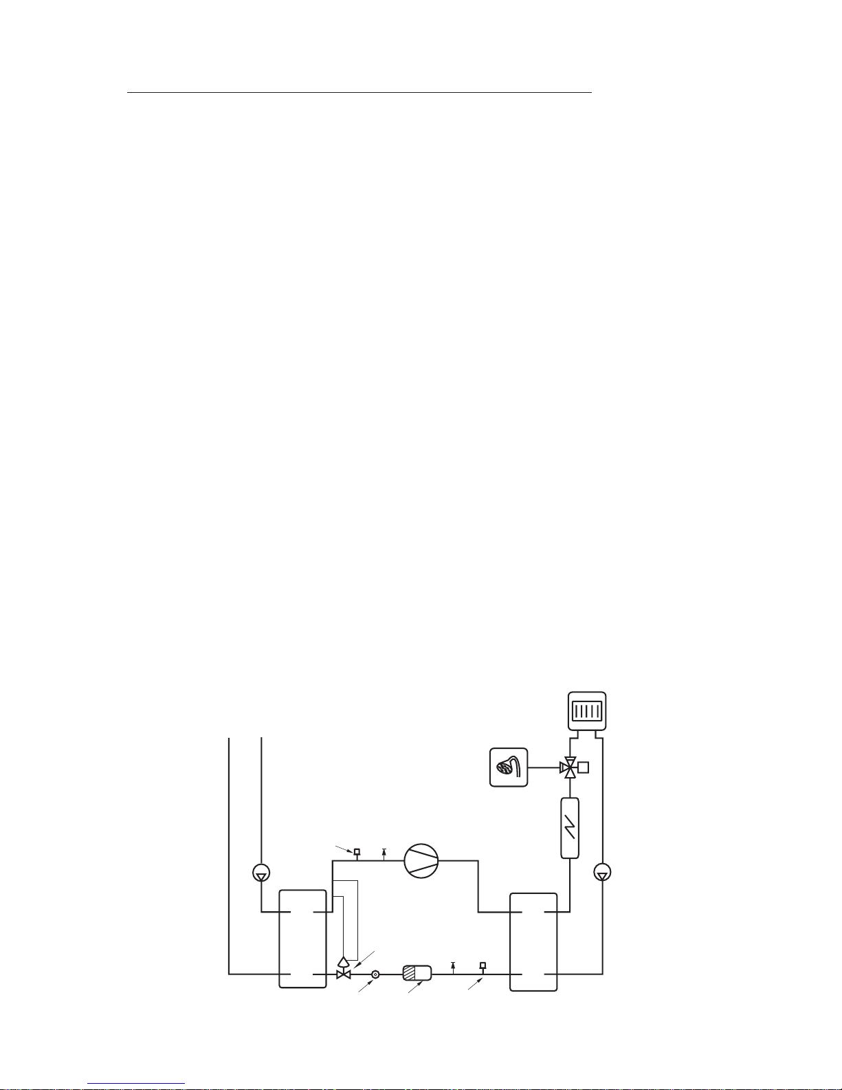
This is how your heat pump works
Heat pump technology
The compressor, which is driven by an electric motor, forces the heat transfer fluid into the heat
pump condenser as a gas at about 100°C. The gas and the water from the radiator system pass
through the condenser, which is a fully-welded stainless steel heat exchanger. When the hot gas is
cooled by the circulating water, it condenses (changes to liquid). As it does so, it provides energy for
the heating system or the hot water. After the condenser, the refrigerant, which is now in liquid form,
continues through a drying filter and a tank. The filtercollects any moisture in the system and the tank
is used as an expansion vessel for the heat transfer fluid to ensure there is always the correct amount
in the condenser.
After the filter, the heat transfer fluid passes through a sight glass. The sight glass is used to check the
amount of heat transfer fluid in the system. In normal operation there should be no bubbles in the
sight glass. However, bubbles may appear for short periods, mainly on rapid changes between hot
water and radiator operation and when the heat pump starts or stops.
After the sight glass the heat transfer fluid goes to an expansion valve. The valve acts as a flow
restrictor between the high and low pressure sides of the system. The valve, which has a sensor
(bulb) just before the compressor, releases the right amount of liquid into the next heat exchanger, the
evaporator. In the evaporator, the liquid meets the circulating heat transfer fluid coming from the
energy source in the ground or bore hole. In this process, the liquid turns to gas (evaporates) under
low pressure, which uses heat. The heat is extracted from the outside air free of charge.
After passing through the evaporator, the heat transfer fluid is once more in the form of a gas (vapour). The expansion valve sensor constantly checks that the evaporator is performing optimally, in
order to use as much free energy as possible. The gaseous refrigerant then goes to the suction side of
the compressor, where it is compressed again. This completes the heat transfer fluid circuit.
Pressure switches are fitted on the high and low-pressure sides of the system to protect the heat
pump. These shut down the heat pump if the pressure in the system reaches an abnormal value. This
is dealt with in more detail in the section on troubleshooting.
Page 8
8
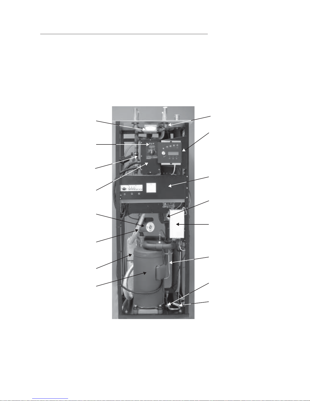
3- way valve that
alternates between
heating and hot water.
Reset buttonfor over-
heat protectionon the
electric heater.
Cleanable particle filter
with cut-off.
Electric boiler.
Circulation pump on
the hot side (G2 (P2)).
Flexible hoses on the
hot side for vibration
free operation.
Condenser.
Compressor with
frequency adapted
soundproof cover.
Electrical connections.
Control panel with
large display.
Sealed electrical box
with resetting of the
motor cutout and
circuit breaker for heat
pump and electric
heater.
Circulation pump on
the cold side
(G3 (P3)).
Control unit Rego 600.
Evaporator.
Sight glass.
Expansion valve.
Greenline 14 and 16 components
NOTE: The picture is of the E series
The D series has two connections on the hot side and does not include a 3-way valve and electric
water heater. The particle filter is supplied separately and is mounted outside the heat pump.
Page 9
9
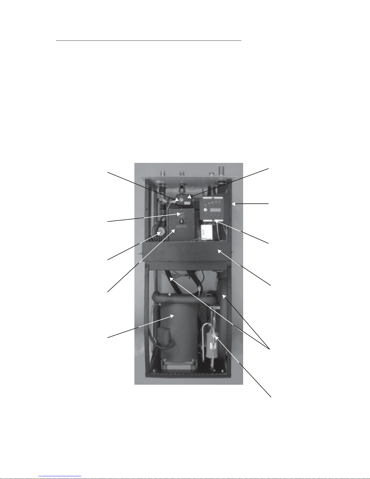
3- way valve that
alternates between
heating and hot
water.
Reset button for
overheat protec-
tion on the electric
water heater.
Circulation pump
(G2 (P2)) on the
hot side.
Electric boiler.
Frequency
adapted sound-
proof cover.
Electrical connections.
Control panel with
large display.
Circulation pump
on the cold side
(G3 (P3)).
Sealed electrical
box with resetting
of the motor cutout
and circuit breaker
for heat pump and
electric heater (the
box is shown
folded up).
Flexible hoses on
the hot and cold
sides for vibration
free operation.
Sight glass.
Greenline 20 – 40 components
NOTE: The picture is of the E series
The D series has two connections on the hot side and does not include a 3-way valve and electric
water heater. The particle filter is supplied separately and is mounted outside the heat pump.
Page 10

10
Principle
Principle of heating and hot water control
Your heat pump is fitted with a Rego 600 control unit to guarantee you maximum savings and many
years of service. The unit, which has advanced monitoring functions, controls the heating and hot
water in your home. This ensures that all vital functions are monitored and that, if problems arise, the
heat pump is shut down before it is damaged.
When the heat pump is not able to meet the heating requirements, supplementary heat is connected
that together with the heat pump provides the required temperature. The Greenline E series has a
built-in electric heater that can be connected in three steps. The supplementary heat only provides
the output that the heat pump cannot generate and in this way can never take over heating the house
completely. When the heat pump is once more able to meet the heating demand, the supplementary
heat is automatically switched off. An oil-fired boiler is normally used to provide supplementary heat
for the Greenline D series. In which case Rego 600 controls the oil-fired boiler and the existing mixer
valve.
The heat pump is connected to the return line of the heating system so that it always receives the
coldest water. The water is heated in the heat pump and is then fed back to the heating system.
While the heat pump is heating the domestic hot water by using the electric water heater, the heating
system is disconnected temporarily through the three-way valve. A sensor in the hot water cylinder
makes sure that priority is always given to heating the hot water. When the water in the cylinder
reaches the required temperature, heat is once more supplied to the heating system.
Power failures
If the power supply fails, the control unit remembers all its settings and re-starts the heat pump when
the power returns.
Three different operating modes
The control unit can be used for three different operating modes: A, B and C. The three operating
modes are described schematically in the Installer chapter.
Operating mode A (D and E series)
This is the factory setting, based on an outdoor sensor and controls the heating temperature through
an adjustable control curve. Water heating takes priority over space heating. As well as operating
the heat pump, Rego 600 can also regulate other heat curves with a mixing valve, e.g. through a
combination of radiator and floor heating systems. An electric water heater is used for additional
heat.
Operating mode B (D series only)
Used when additional heat is from an oil-fired boiler. Operation is the same as for operating mode A.
Rego 600 cannot control other heat curves in this operating mode.
Operating mode C (D series only)
Used in exceptional cases, it does not provide optimal operation for the heat pump because it always
works with a high temperature, or “Fixed Temperature”. This is often used in operation with one or
more accumulator tanks. The tank is always kept at a high temperature and the hot water is often
heated in one or more coils.
Page 11

11
Controls
The control unit operates the heat pump in three ways. We call them Curve Control, Room Sensor
and Fixed Temperature. Below follows a brief description.
Curve control (operating modes A and B)
This is the most common mode and is also the factory setting. With curve control, the heat pump
adapts the heating inside the house on the basis of the outside temperature. An outside sensor sends
signals to the control unit, which automatically adjusts the supply of heat to the heating system. This
maximises savings, since the heat pump never needs to work at a higher temperature than necessary.
The heat pump only delivers the maximum temperature when heating the hot water. Normally, hot
water heating accounts for 20% of the total annual energy requirement.
Room sensor (operational modes A and B)
A room sensor can be connected to the heat pump. It sends signals to the control unit and in this way
affects the curve control. The sensor influences the curve control and the amount of influence can be
set on the control panel. Normally, room sensors are only used when a fan-assisted radiator is used
in a house with direct electric heating or when a wood-burning stove is used in the house or where
the house is effected by wind chill or solar gain.
Fixed temperature (operating mode C only)
This control technique is rarely used, and does not offer optimum savings from the heat pump. The
principle is that the heat pump is switched on and off by the built-in return sensor and always works
up to its maximum working temperature. The normal area of use for this is together with existing
accumulator tanks.
Page 12
12
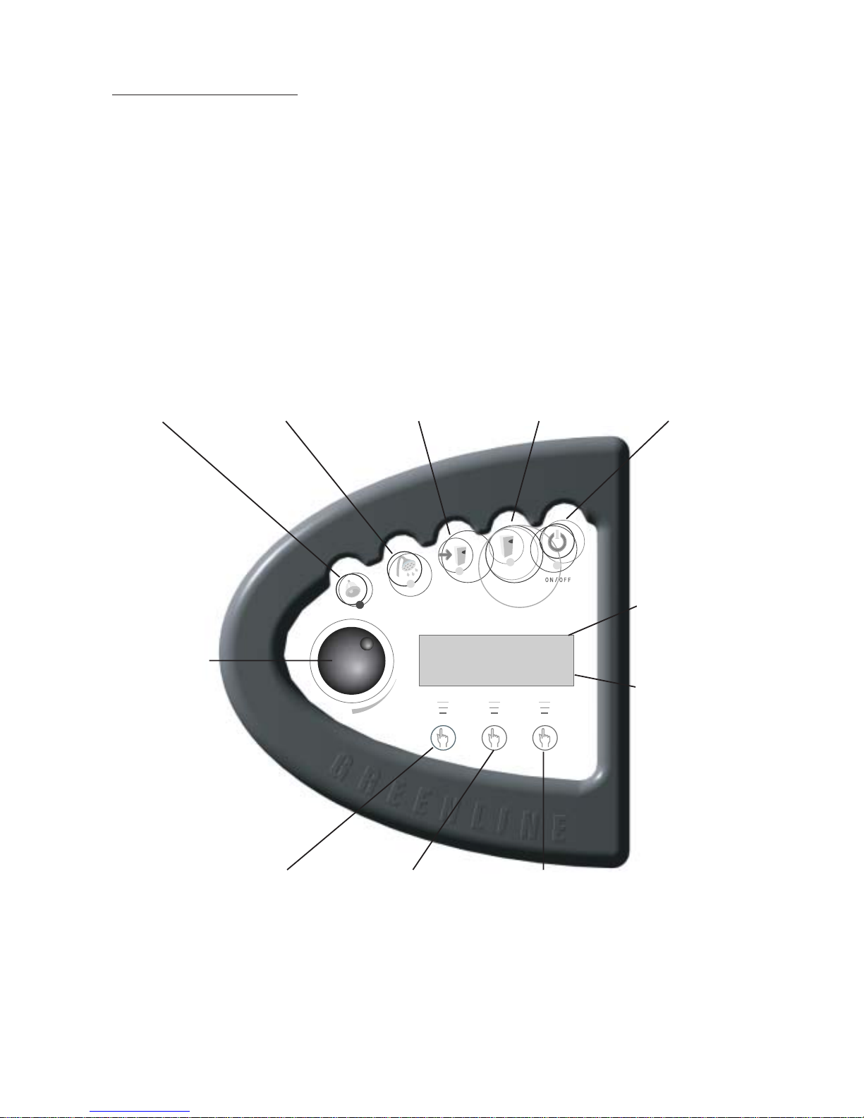
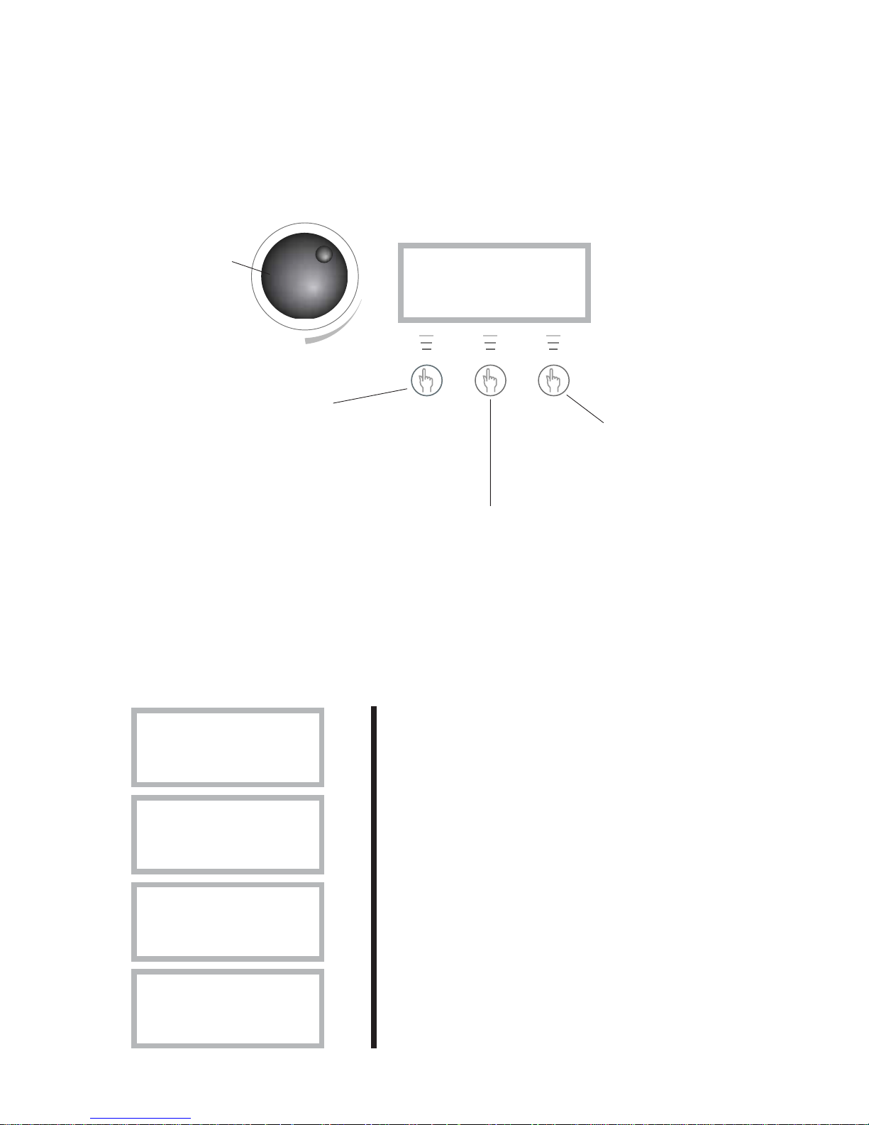
Control panel
Control panel buttons and displays
The control panel is the heart of your heat pump installation. From the control panel, instructions are
sent to the Rego 600 control unit, which ensures that the house is uniformly heated. All settings are
carried out here and the display shows the settings that have been set.
Rego600 K1
020301 12.00.00 Fr
Heat Info Menu
The heat pump is in
operation when this
lamp is lit.
This lamp is lit when
the heat pump needs
additional heat.
This lamp is lit when
hot water is being
heated. It blinks
during hot water
peaks and additional
hot water.
This lamp blinks
when a fault has
occurred.
This switch is used
to turn the heat pump
on and off. The heat
pump is in operation
when the lamp is lit
The heat pump is off
when it blinks.
This dial is used to
navigate the menu
and to change
settings.
This shows you
which user level
you are in.
This display
shows information such as text
and temperatures.
Press once to come
to the complete
menu for settings
and temperatures.
Press once for
continuous information about operation
conditions for the
heat pump and
additional heat.
Press once for a
short cut to the
heating settings.
Page 13
13
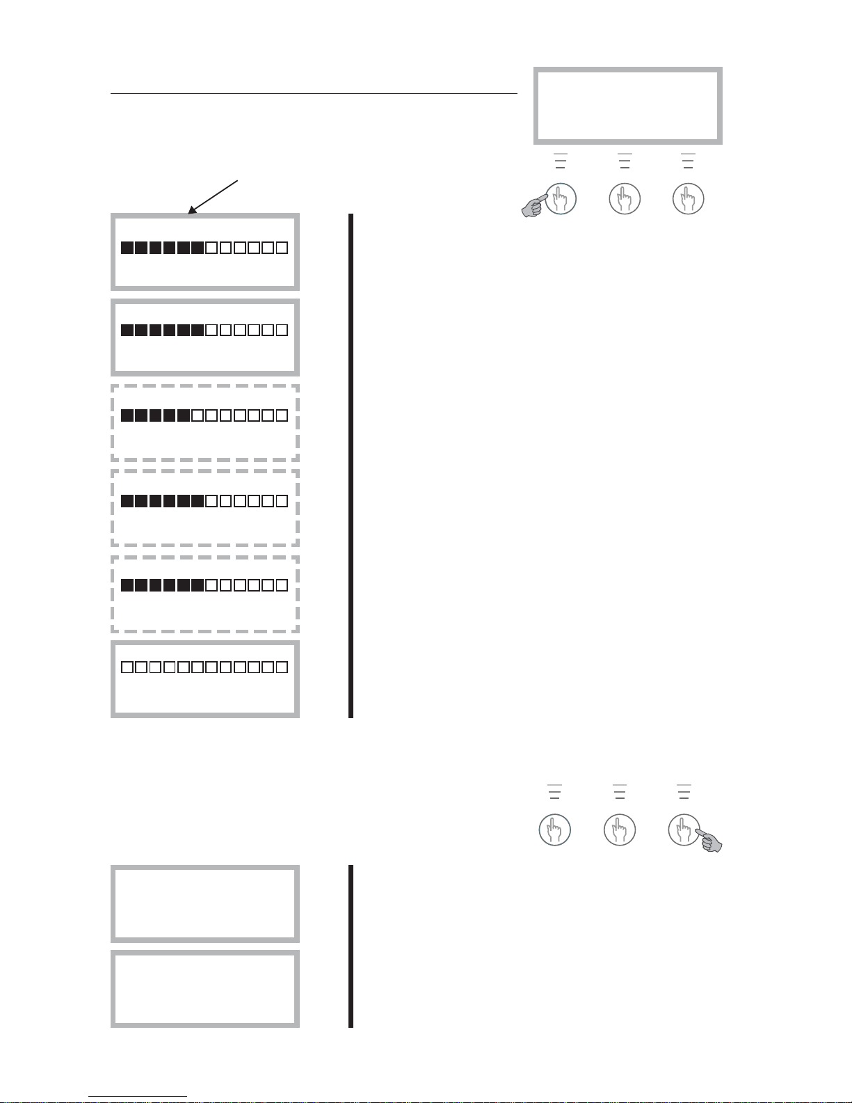
Examples of scrolling information
Here are some of the displays you see if you choose
scrolling information with the “Info” button:
Heat pump is not operating.
The heat pump is producing hot water and you see the
current temperature and the temperature it stops at.
The heat pump and additional heat is in operation.
A need for heat has arisen and the heat pump is waiting for
the reset time to count down to zero.
STANDBY
No rad heat required
No hot water
required
HOTWATER MODE
Heat pump only
Stop temp 47.5°
Present temp 42°
HEAT RAD MODE
Compr. + Add. heat
Stop temp 45°
Present temp 44°
HEAT RAD REQUIRED
Heat pump starts
in 320 seconds
How to use the control panel
With the help of three buttons and a dial you can navigate to the various displays for settings and
readings. The last line at the bottom of the display contains information about the functions of the
buttons in the current display. If you choose “Heat” or “Info” the display you have chosen to stay in
will always remain.
Press “Heat” once more
and you come to the
shortcut for heat settings.
You can choose to stay in
which display you want.
Press “Info” once and you receive continuous information about what
the heat pump is doing and at which temperature it stops at. You can
choose to remain in this display and always receive this information.
Press the middle button again to return to the first display.
Press “Menu” once and
you come to the main
menu for settings or
temperature readings.
With the dial you
navigate up and
down between
the displays or
change the
settings.
Rego600 K1
020301 12:00:00 Fr
Heat Info Menu
Page 14
14
House heating settings in areas 0 to 10. See more detailed
description in “Heat Settings” chapter.
Fine adjustment settings in areas -10°C to 10°C. See more
detailed description in “Heat Settings” chapter.
Here you can set the heat in areas 0 to 10 if you use an
extra heat curve with a mixing valve.
Here you set the fine adjustment of the mixing valve curve
in –10°C to 10°C.
If a room sensor is connected you can set the required
room temperature here. On customer level 2 you can set
how much you want the sensor to affect the heating system.
You can temporarily increase the hot water temperature
with the electric water heater here. The heat pump first
increases it to around 50°C and then the electric water
heater to around 65°C. The electric heater starts again at
60°C and increases the temperature to 65°C in the set
time. The area is 1-48 hours and when the set time has
elapsed the settings must be repeated in order to receive
extra hotwater.
With extra
sensor
only.
With
extra
sensor
only.
With
extra
sensor
only.
Operating mode
A only.
The radiator temperature settings you make in the short cut
to “Heat” can also be made on row 1 and for the hot water
setting on row 2.
In row 3 you can see all the temperatures where sensors
are connected.
Main menu
Monitor all
temperatures 3
Return Select
Main menu
Indoor temperature
settings 1
Return Select
Extra hotwater
1h 0h 48h
Return Adjust
Room temperature
10° 20° 30°
Return Adjust
Mix. valve fine-tune
-10° 0,0° 10°
Return Adjust
Mix. valve incr/decr
0 4 10
Return Adjust
Temp. fine-tune
-10° 0,0° 10°
Return Adjust
Temp. incr. / decr.
0 4,0 10
Return Adjust
Basic functions (customer level 1)
Heating and extra hot water
Press “Heat” to come to the short cut to the heat settings. These
displays are then available.
Rego600 K1
020301 12:00:00 Fr
Heat Info Menu
Temperatures
Press “Menu” to come to the main menu. Where you can also carry
out heat settings and see the temperatures. These displays are then
available.
Page 15
15
You have pressed “Menu” and are on row 1. Press “Select” and turn the dial and the display will scroll. You can
then choose to enter the display you require. Each display
has a number.
With a room sensor installed you can set the value here how
much you want it to affect the outdoor sensor. A high value
gives more effect from the room sensor. Please note the
room sensor only fine tunes the heat curve. It is therefore important that you set the basic settings for the
heat curve and fine tuning from the start.
If a room sensor is installed you can utilise the holiday mode
function, you can set the number of days that the room
temperature is lowered to 15°C here. The temperature is
not adjustable and it does not affect the hot water. Normal
operation is resumed when the period is over.
If a room sensor and remote control is installed you can set
the required room temperature here. You can then use the
telephone to increase the temperature to normal.
This equipment is available as an accessory.
At this set temperature the heat pump only produces hot
water.
Line 1
With extra
sensor and
in operating
mode A
only
With extra
sensor
only
With extra
sensor,
remote
control
and in
operating
mode A
only
Operating
mode A
and B only
Operating
mode A
only
Using the dial you have moved to the hot water settings in
row 2.
Setting intervals for the continual raising of the hot water
temperature. If you choose for example 7 days, the temperature is raised using the electric water heater once a
week to around 65°C (Operating mode A with electric
water heater only).
Line 2
Hot water setting
Interval for
hot water peak 2.2
Return Select
Main menu
Adjusting the hot
water settings 2
Return Select
Temperature settings
Setting of summer
disconnection 1.14
Return Select
Temperature settings
Remote control
temperature 1.13
Return Select
Temperature settings
Setting of holiday
function 1.12
Return Select
Temperature settings
Setting of room
sensor infl. 1.11
Return Select
Main menu
Indoor temperature
settings 1
Return Select
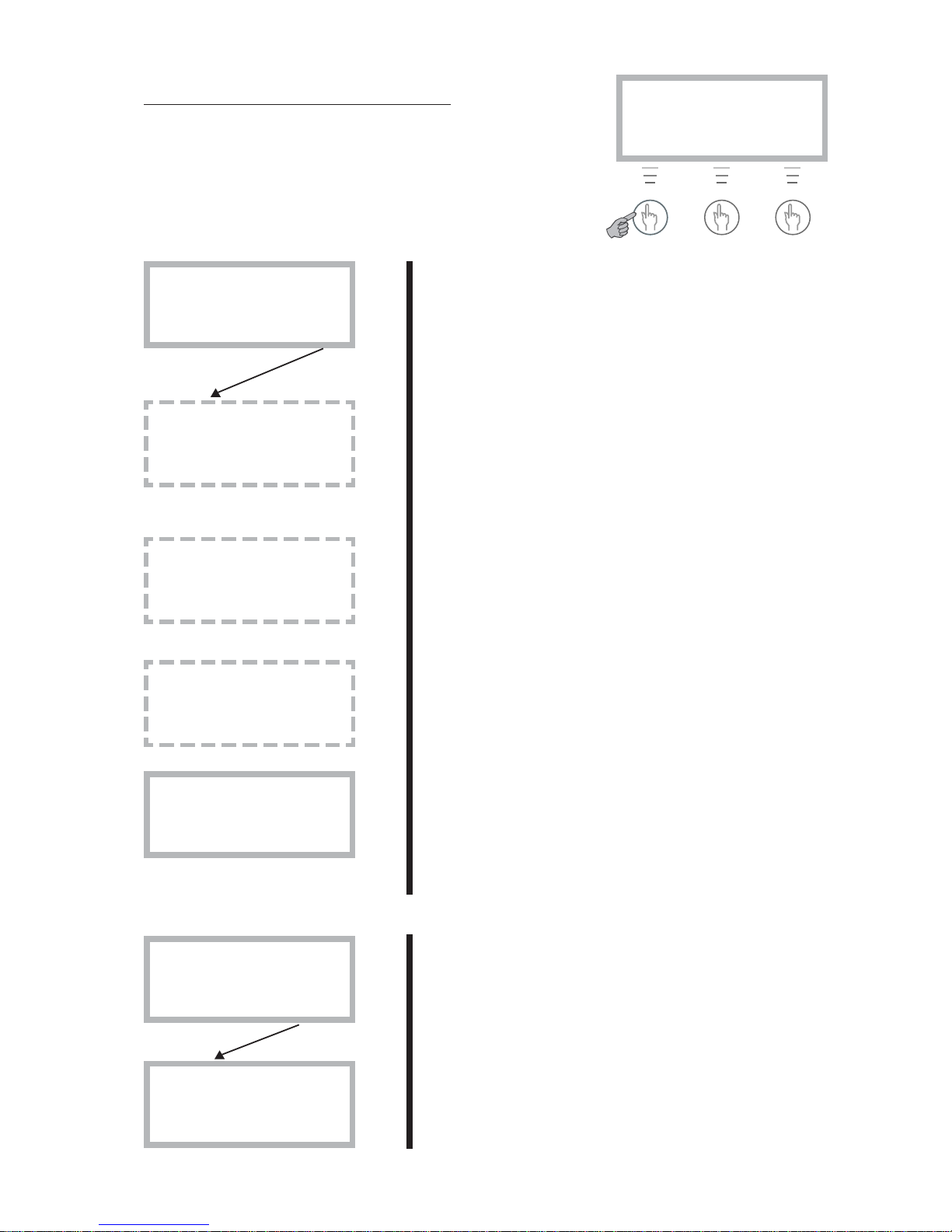
Enhanced functions
As a user you have access to enhanced functions. Keep the
“Heat” button pressed down for five seconds and go into ”Menu”
to gain access to these displays. You will automatically return to
level 1 again after 30 seconds.
Keep the button pressed
down for 5 seconds.
Rego600 K2
020301 12:00:00 Fr
Heat Info Menu
Page 16

16
Line 4
You have now moved to timer control settings line 4.
Here you can set the times, day for day, that you want to
utilise the clock settings. You can set all the weekdays
independently of each other. Press “Select”.
The example describes how you set Monday between
22:00 and 06:00. Press “Adjust”.
There is now a cursor under Monday. Turn the dial and mo
becomes Mo. Monday is now activated.
Now set the clock setting to between 22:00 and 06:00 in
the morning. Press the right arrow button until the cursor is
under the first 00. Turn the dial until 22:00 appears. Press
the button twice more (the cursor moves two steps to the
right) and turn the dial until 06:00 appears. Press the ”right
arrow” button once more and the arrow is replaced by
“Save”. Press “Save” to set the timer controls.
You can now do the same for all the other days of the
week you want to timer control. Use the dial in this display
to access other days.
In display 4.1.1 you set how much you want the temperature to be raised or lowered in the above time zone settings. If you choose, for example, –5°C the heating system
temperature is lowered by 5°C.
In display 4.3 you can disconnect the hot water completely
during e.g. peak rate times. This is done in the same way as
with the heat pump time controls.
Not
operating
mode C
Tidsstyrning
Tidsstyrning tillsk.
enligt klocka 4.2
Tillbaka Välj
Clock setting
Setting level
heat pump +/- 4.1.1
Return Select
Clock setting HP 1
Mo 22:00-06:00
Return Adjust
Clock setting HP 1
Mo 22:00-06:00
^^
Cancel <- ->
Clock setting HP 1
Mo 00:00-00:00
^^
Cancel ->
Clock setting HP 1
mo 00:00-00:00
Return Adjust
Clock setting
Clock setting HP
accord. to clock 4.1
Return Select
Main menu
Timer control
settings 4
Return Select
Page 17

17
Line 7
Not
operating
mode C
Not
operating
mode C
Line 10
Line 11
Line 12
Main menu
Return to
factory settings 12
Return Select
Main menu
Alarm logging
of all alarms 11
Return Select
Main menu
Clock, setting
time and date 10
Return Select
Op. time readings
Distribut. add. heat
DHW-Rad in % 7.4
Return Select
Op. time readings
Add. heat in operat.
number of hours? 7.3
Return Select
Op. time readings
Distribution HP
DHW-Rad in % 7.2
Return Select
Op. time readings
Heat pump in operat.
number of hours? 7.1
Return Select
Main menu
Op. time readings on
HP and add. heat 7
Return Select
In line 7 you can read the running times for the heat pump
and additional heat. Press “Select” to enter these menus.
Here you can see how many hours the heat pump has been
in operation.
This shows the distribution of the heat pump between hot
water and heating as percentages.
Here you can see how many hours the additional heat has
been in operation.
This shows the distribution of the additional heat between
hot water and heating as percentages.
You can set the heat pump’s clock to the correct time if it is
wrong on line 10.
Line 11 shows a record of the alarms that may have occurred on your heat pump. You can see the type of alarm
and when it occurred. An * in the display means the alarm is
still active.
If you want to change your settings at customer levels 1 and
2 you can return to factory settings on line 12.
Please note: If you are on the installer/service level when
you choose factory settings, the installer must carry out a
new start-up of the plant with the new settings. The installer/
service level is for installer only. As an end-user you should
never go into this level!
Page 18
18
Cold weather:
If the indoor temperature is too low or too high during cold
weather, you use Temp. incr./decr. to change it.
Press “Heat”.
The set value is shown on the display; in the shape of a bar
but also as a digit. The range is between 0 and 10. Press
“Adjust”.
Turn the dial to the right to increase, to the left to decrease.
The example shows how you increase the value to 5. Turn
the dial until 5 appears on the display. The new value now
appears on the display. Press “Save” to save the new
value.
Rego600 K1
020301 12.00.00 Ti
Heat Info Menu
Temp. incr. / decr.
0 4 10
Return Adjust
Temp. incr. / decr.
0 5 10
Return Save
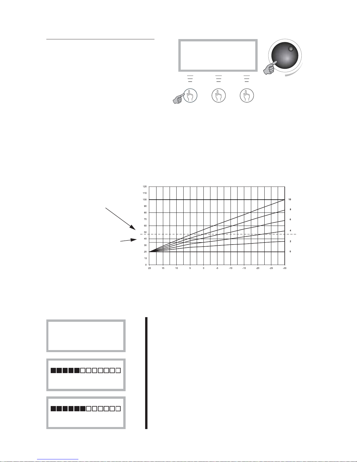
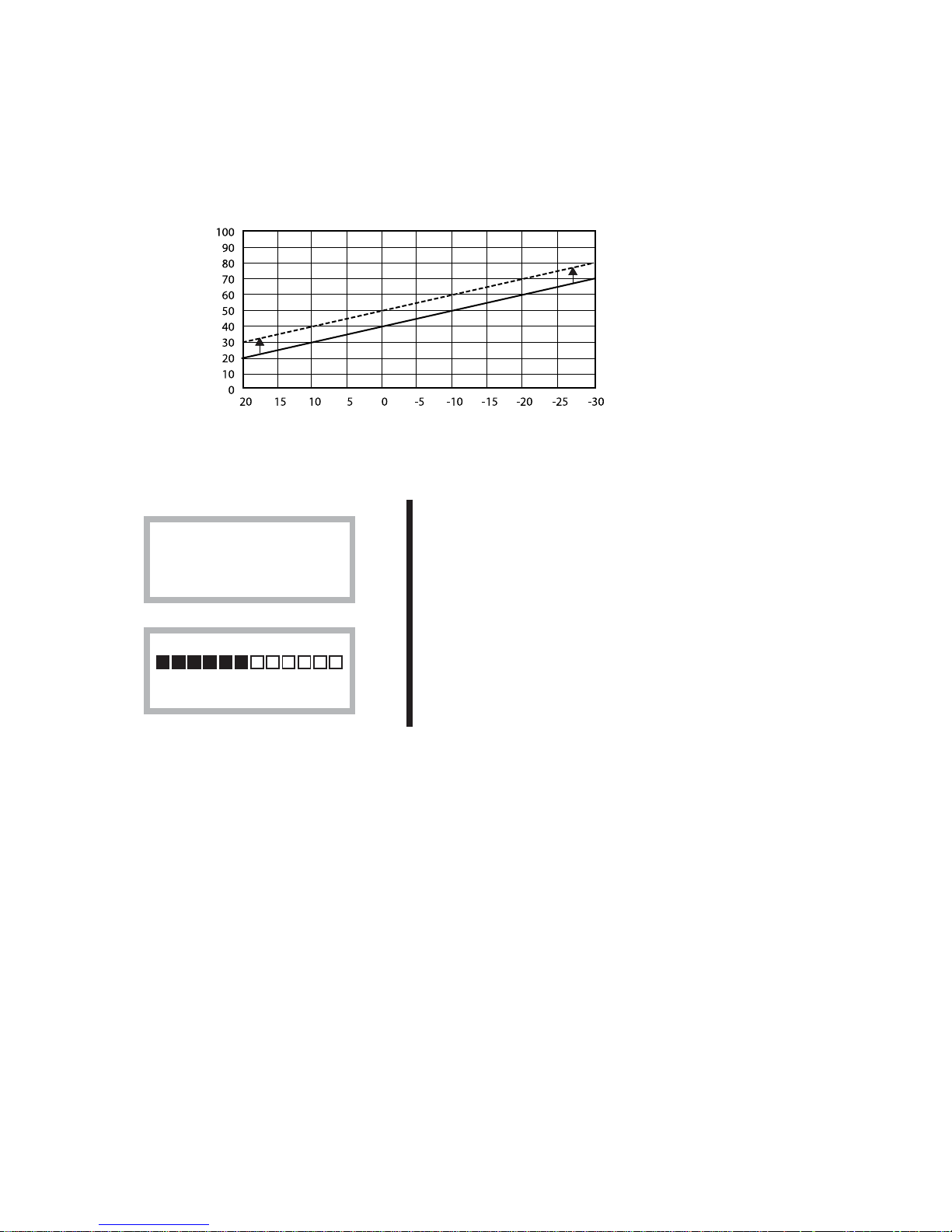
Setting the heating
In the Temperature “increase/decrease” display
you use the dial to change the heat curve. The
lines show how the return temperature varies
with the outside temperature for different settings. The colder the weather the warmer the
heating system. Curve 4 is the factory setting
and in the example you can see that this gives a
return temperature of around 35°C at an outdoor temperature of 0°C.
Please note that the flow temperature is then around 7-10°C warmer. During the first winter, the
heating curve must be set up so that the temperature in the house is pleasant whatever the weather. You
should adjust the heating curve when the outdoor temperature is around 0ºC. You should wait two days
after adjusting before carrying out any readjustments.
Rego600 K1
020301 12:00:00 Fr
Heat Info Menu
The example describes how to change the “heat curve” in the Heating increase/decrease menu.
Please note that a high value could cause the heat pump to stop if the return temperature is too high.
Heat curve
Radiator return
temperature
Setting
Outdoor temperature
The appearance of the heat curve
The limit when the heat
pump stops for a too
high a return temperature.
The line shows that if heat
curve 4 is chosen, the heat
pump stops at around 35°C
when the outdoor temperature is 0°C.
Page 19
19
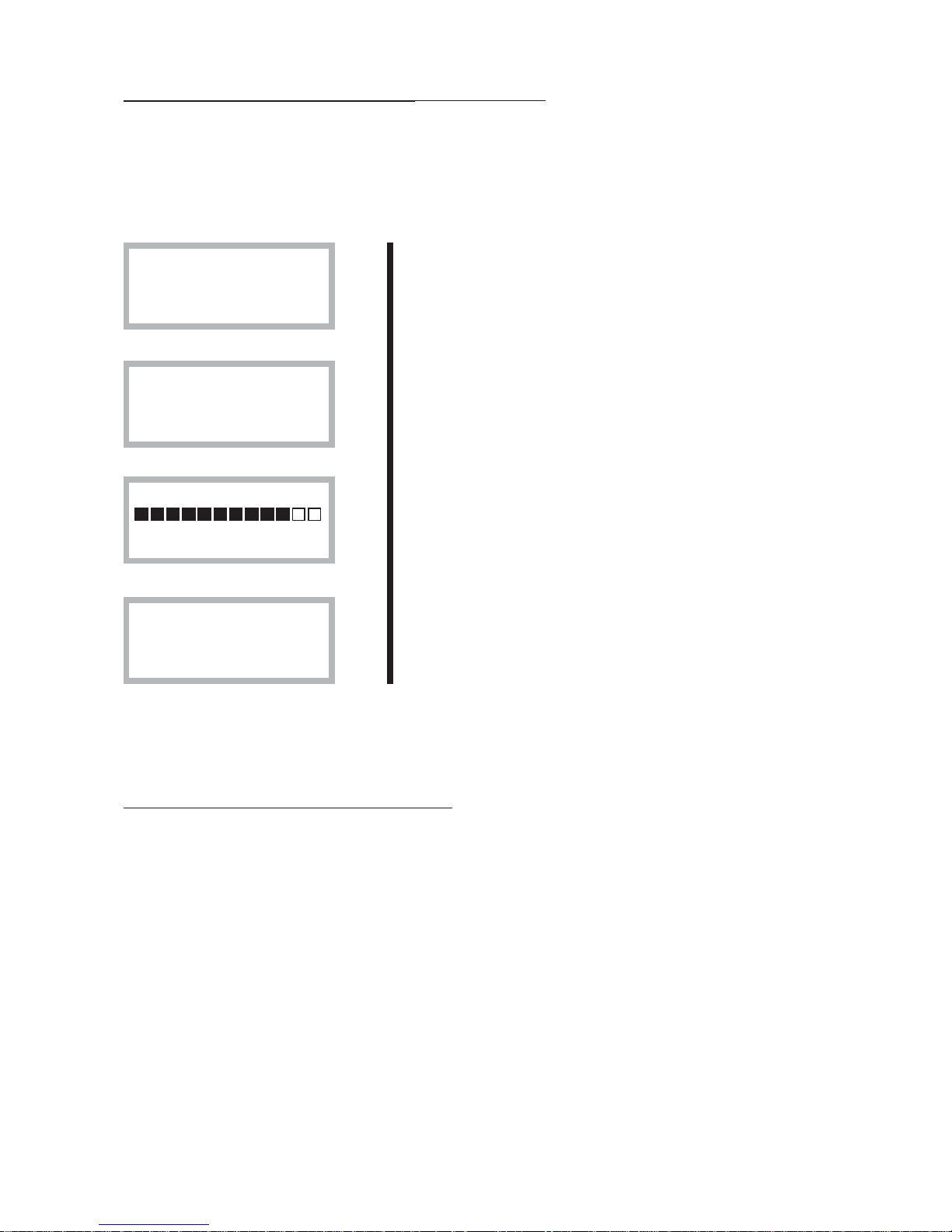
Warm weather (above +5ºC):
If the indoor temperature is too low or too high during
warm weather, you use fine tuning to change it. You come
to Temp. Fine Tuning by pressing “Heat” and turning the
dial to the right.
Fine tuning can be set in areas –10°C to 10°C. You change
the fine tuning in the same way as “Temp. increase/decrease” as described on the previous page.
The heat curve can also be fine tuned. You do this in the “Temp. fine tune” display. The dotted line
illustrates how the parallel offset has been turned towards plus. The entire curve moves upwards, in
contrast to increasing the slope, when only the slope changes.
The dotted line illustrates
how the fine tuning adjustment has been turned
towards plus.
Fine tuning adjustment
Radiator return
temperature
Outdoor temperature
Rego600 K1
020301 12:00:00 Fr
Heat Info Menu
Temp. fine-tune.
-10° 0,0° 10°
Return Adjust
Page 20
20
Fixed temperature (D series only)
If the heat pump is set at operating mode C with a fixed temperature, then it can only be engaged
and disengaged by the built-in return sensor. There are two displays available for this mode. Please
note that if a mixing valve is connected to the heat pump, the “Temp. incr/decre” and “Temp. fine
tune” displays control the settings for the mixing valve opening to the heating system.
Rego600 K1
020301 12.00.00 Ti
Heat Info Menu
To adjust the engaging and disengaging temperature, press
“Menu” followed by “Select”. You are now in line 1.
Use the dial to navigate to display 1.16 and press “Select”.
The factory setting is 48°. Please note that this concerns the
engaging temperature to the heat pump. The temperature
from the pump is normally 5-10°C higher. Settings above
48°C are not recommended for technical reasons.
You can also set the difference between engaging and
disengaging the heat pump in display 1.17. The factory
setting is 5ºC. A lower setting results in the heat pump
starting and stopping more frequently. Press “Select” to
adjust.
Simple tips for saving
The lower you can keep the temperature of the heating system in the house, the better your heating
economy will be. So make sure not to set your heat curve too high. It is important that the heating
system is carefully balanced so that all parts or the heat emitters (radiators or underfloor) are at the
same temperature.
Thermostatic valves on your radiators or floor heating may have a negative effect on your heating
system because they restrict the flow so that the system has to compensate with a higher water
temperature. If thermostat valves are fitted, they should be fully opened, except in bedrooms, where
they can be turned down slightly.
Temperature settings
Return thermostat
stop temp sett. 1.16
Return Select
Return thermos. stop
30° 48° 50°
Return Adjust
Temperature settings
Return thermostat
hysteresis set 1.17
Return Select
Page 21

21
All sensor temperatures
Below are the various sensor temperatures that are visible under line 3 in the control panel. Note that
not all the sensors are standard but are available as accessories for different areas of use. To get
there press “Menu” in the control panel and then turn the dial to line 3. Then press “Select”.
Shows the heating system return temperature. This varies
depending on the outdoor temperature.
Shows the outdoor temperature.
Shows the temperature in the outer container of the electric
water heater’s bottom part. This temperature is around 5°C
lower than the temperature in the hot water tank.
If an extra mixing valve is used for e.g. floor heating then
the flow pipe is visible on the circuit. It varies with the
outdoor temperature.
If a room sensor is used, you will see the temperature of the
room where the sensor is located.
The sensor shows the working temperature of the compressor. It varies between around 70°C and 135°C.
The sensor shows the outgoing temperature from the heat
pump. It varies depending on the outdoor temperature and
whether the heat pump is in hot water production mode.
The sensor shows the incoming temperature to the heat
pump. It varies as mentioned above. Please note that for
safety reasons the heat pump stops when this shows a
temperature of more than 48°C.
The sensor shows the temperature from the bore hole or
the ground. It normally varies between -5°C and 8°C
throughout the year.
The sensor shows the temperature to the bore hole or the
ground. It is normally 1.5°C to 5°C lower than heat transfer
in.
Line 3
Standard
Standard
Included
with
the C series
Accessories
Accessories
Standard
Standard
Standard
Standard
Standard
Temperature readings
Return radiator GT1
Off ##,#º Now ##,#º
Return
Temperature readings
Out GT2
###,#°
Return
Temperature readings
Hot water GT3
Off ##,#º Now ##,#º
Return
Temperature readings
Shunt, flow GT4
Tgt ##,#º Now ##,#º
Return
Temperature readings
Room GT5
Tgt ##,#º Now ##,#º
Return
Temperature readings
Compressor GT6
###,#º
Return
Temperature readings
Heat tr fluid out GT8
###,#º
Return
Temperature readings
Heat tr fluid in GT9
###,#º
Return
Temperature readings
Ht tr fld(coll)inGT10
###,#º
Return
Temperature readings
Httrfld(coll)outGT11
###,#º
Return
Page 22

22
If the control panel is dark
Possible faults:
• The fuses or MCBs (miniature circuit-breakers) in your fuse box.
This is what to do:
Check the fuse (or MCB) for your heat pump. If the small plate at the bottom of the fuse has come
off, the fuse has blown and must be replaced. If you have MCBs, and they have tripped, move the
switch to the up position.
Note that the heat pump cannot restart until after 15 minutes. This delay is needed for technical reasons!
• The heat pump MCB has tripped
This is what to do:
Reset the MCB by pushing the switch upwards.
If something is wrong
The control unit provides a lot of information about faults and how to remedy them. Rego 600
incorporates advanced functions to monitor and protect your heat pump. This means there is no risk
involved in resetting an alarm. If a fault persists, you should contact the installer.
Alarm examples and what to do
Press “Ackn” when the fault is remedied, the alarm lamp goes off and the
heat pump starts again within 15 minutes. If the lamp is lit with a steady glow
then the alarm is remedied, but the fault
remains. If several alarms have triggered, use the dial to navigate to them.
If you press “Info” and then turn
the dial you will see information
about the possible causes and
how you can remedy the fault
yourself.
ALARM
Power failure
020301 15:10:18
Info Ackn.
Time and date for
when the fault
occurred.
Cause.
Page 23

23
All alarms
Below is a description of the alarms that can appear in the menu display. The description gives an
idea of what the fault is and what you yourself can check and remedy. An alarm can sometimes
occur temporarily so there is never any risk with resetting it. If a fault persists, you should contact the
installer.
The description sometimes refers to a heat pump component. Pages 28 and 29 have details of where
to find the components. Page 28 is for models 14-16 and page 29 is for models 20-40.
COMPRESSOR MOTOR CUTOUT SWITCH ALARM
To reset the alarm: Reset the motor cutout by pressing in the
black button (position 2). Then press “Ackn.” Note: The lamp
goes out even if the motor cutout has not been reset. (Models
25-40 have built-in temperature protection in the compressor
that resets automatically when the temperature has reduced).
ALARM (MB1)
Compr. circ. Switch
020301 15:10:18
Info Ackn.
Probable causes and actions:
• Sporadic fault or overloading of the power supply.
Action: Reset the motor cutout and wait and see.
• The current setting on the motor cutout is too low. The compressor’s current intensity varies during
summer/winter operation.
Action: Contact the installer.
• Contactor or cutout faulty, or loose electrical connections to the compressor.
Action: Contact the installer.
• Compressor faulty.
Action: Contact the installer.
ALARM (MB2)
HTF c-pump switch
020301 15:10:18
Info Ackn.
HEAT TRANSFER FLUID CIRCULATION PUMP
SWITCH ALARM
To reset the alarm: Greenline 14-16. Press “Ackn.” (Mod-
els 14-16 have built-in motor cutout in the pump that resets
automatically after a period of time). Greenline 20-40. Reset
the circuit breakers (pos 3) or the pump built-in motor cutout
(pos 9) and press Confirm. Note that the lamp goes out even if
the motor cutout has not been reset.
Probable causes and actions:
• The pump has stopped because of contaminants.
Action: If the pump has an air vent screw it can be loosened and the pump restarted with a screwdriver
• Fault in the pump’s electric motor.
Action: Contact the installer.
• Temporary fault.
Action: If the fault persists, contact the installer.
Page 24

24
LOW PRESSURE SWITCH ALARM
To reset the alarm:
Press “Ackn.”
ALARM (LP)
Low pressure switch
020301 15:10:18
Info Ackn.
Probable causes and actions:
• Air in the heating system.
Action: Check the expansion vessel and fill if required. If air is heard continuously in the system,
contact the installer.
• Heat transfer pump has stopped or is set at too low a speed.
Action: Check the pump has not stopped or is set at the wrong speed.
• Particle filter on the cold side is clogged.
Action: Check the particle filter and clean if necessary.
• Not enough refrigerant in the circuit.
Action:Check that bubbles do not appear continuously in the sight glass. Contact the installer.
• Not enough antifreeze in the heat transfer circuit creating ice in the heat exchanger.
Action: Contact the installer.
• Expansion valve faulty (alarms occur at long intervals, about every three or four weeks).
Action: Contact the installer.
HIGH PRESSURE SWITCH ALARM
To reset the alarm:
Press “Ackn.”
ALARM (HP)
High press. switch
020301 15:10:18
Info Ackn.
Probable causes and actions:
• Air in the heating system.
Action: Check the system and vent the radiators if necessary.
• Not enough flow over the heat pump.
Action:Check that the circulation pump has not stopped and that a valve in the system is not closed.
• Particle filter on the hot side is clogged.
Action: Check the particle filter and clean if necessary.
• Heat transfer fluid circuit over-filled.
Action: Contact the installer.
• Drying filter clogged.
Action: Contact the installer.
Page 25

25
ALARM ON COMPRESSOR SUPERHEAT
To reset the alarm:
Press “Ackn.”
Probable causes and actions:
• The working temperature of the compressor is too high.
Action: If the fault persists, contact the installer.
• Sporadic temperature rise due to abnormal operating conditions.
Action:Wait and see.
ALARM (GT6)
Compr. superheat
020301 15:10:18
Info Ackn.
PHASE SEQUENCE FAULT ALARM
To reset the alarm: The alarm does not reset until the
phase sequence has been changed. Then the heat pump
starts automatically.
Probable causes and actions:
• Phase sequence to the heat pump is incorrect.
Action: The phase sequence to the incoming supply must be changed.
POWER FAILURE ALARM
To reset the alarm: The alarm resets itself and the heat
pump starts automatically when the fault has been corrected.
Probable causes and actions:
• One or two phases are missing to the heat pump.
Action:Check the fuse (or MCB) for your heat pump. If the bottom plate is loose then the fuse has
blown and must be changed. If you have MCBs, and they have tripped, move the switch to the up
position.
• The emergency thermostat is not in the 0 position.
Action: Check that the emergency thermostat wheel is turned to the anti-clockwise end position.
ELECTRIC WATER HEATER ALARM
To reset the alarm: Reset the water heater’s MCB (pos
4) or overheat protection (pos 5). Press Ackn.
Probable causes and actions:
• The electric water heater MCB has tripped.
Action:Reset the MCB by pushing the switch upwards. If the fuse blows again then the heater could
be faulty, contact your installer.
• The overheat protection on the electric water heater has tripped.
Action: Reset by pressing the button on heater’s protective cover until it “clicks”. It could depend
on a bad flow over the heater caused by the circulation pump standing still or a clogged particle filter.
Check the circulation pump and particle filter.
ALARM (EK)
Electrical cassette
020301 15:10:18
Info Ackn.
ALARM
Power failure
020301 15:10:18
Info Ackn.
ALARM
3-phase incorrect
020301 15:10:18
Info Ackn.
Page 26

26
ALARM, HIGH RETURN TO THE HEAT PUMP
To reset the alarm: The alarm resets itself and the heat
pump starts automatically when the temperature has
dropped.
ALARM (GT9)
High return HP
020301 15:10:18
Info Ackn.
Probable causes and actions:
The heat pump has a sensor that stops the heat pump for safety reasons when the return temperature is
too high, about 48°C
• The temp. incr/decr dial is set so high that the heating system return temperature is too high.
Action:Reduce the temp. setting.
• The hot water temperature is set too high.
Action: Contact the installer.
• The radiator valves or the underfloor heating system are closed.
Action:Open the valves.
• The flow across the heat pump is greater than the flow in the heating system.
Action: Reduce the speed of the heat pump circulation pump or increase the speed of the main pump
in the heating system. Contact the installer.
SENSOR ALARM
To reset the alarm: The alarm resets itself and the heat
pump starts automatically when the fault has been corrected.
ALARM (GT1)
Sensor return rad.
020301 15:10:18
Info Ackn.
Probable causes and actions:
Alarm if a sensor fault can be indicated for all sensors that are connected to the heat pump. The example shows the alarm for the Return radiator, GT1 sensor. The principle is the same for all sensor alarms.
• Short circuit or broken cable to sensor.
Action: If you have an instrument that can measure resistance, you can check the resistance of the
circuit and compare with the table for sensors in Technical spec. Or contact your installer.
• Faulty sensor.
Action: Contact the installer.
• Faulty connection.
Action: Contact the installer.
• Temporary fault.
Action:Wait and see.
HEAT TRANSFER FLUID SYSTEM OUT MAX
ALARM
To reset the alarm: The alarm resets itself and the heat
pump starts automatically when the temperature has
dropped.
ALARM (GT8)
HTF out max
020301 15:10:18
Info Ackn.
Probable causes and actions:
The heat pump has a sensor that stops the pump for safety reasons when the outgoing temperature is
too high at around 75°C.
• Not enough flow over the heat pump
Action:Check that the circulation pump has not stopped and that a valve in the system is not closed.
• Particle filter on the hot side is clogged.
Action: Check the particle filter and clean if necessary.
Page 27

27
Maintaining your heat pump
Your heat pump normally requires little maintenance, but we recommend occasional checking to
ensure that your heating installation is giving the best possible performance. The description
sometimes refers to a heat pump component. You will find these on page 28 for models 14-16
and page 29 for models 20-40.
Working on the heat pump
• Switch off the electrical supply before commencing work on the heat pump. Usually there is an
isolating switch on the wall before the heat pump.
• Only an accredited refrigeration company is permitted to work on the heat transfer fluid circuit.
The installation contains gases that may form toxic fumes when combined with discharges and
naked flames. The gas that forms may cause choking even at low concentrations. If it should leak,
evacuate the room until it has been thoroughly aired.
Normal maintenance
Points to check a few times a year:
• Sight glass (pos 7): When the heat pump starts, and during rapid temperature changes, you can
sometimes see bubbles in the liquid in the heat transfer fluid circuit for a minute or so. This is
normal.
If there are always bubbles in the sight glass: Contact the installer.
Sight glass
• Expansion vessel: If the heat pump has a plastic expansion vessel connected to the heat transfer
circuit the level must not fall below 1/3 (the vessel is mounted outside the heat pump).
For low fluid level: With the pump working, remove the lid to the valve at the top of the vessel
and open the valve. Fill with antifreeze or clean water (simplest with a watering can). Shut the
valve again and screw on the lid.
Ball valve with lid
Emergency operation, E series
If a fault occurs that you cannot remedy, the plant can operate in emergency mode. In this mode the
circulation pump and electric heater are started manually by turning the thermostat wheel on the
electric heater. To get both heating and hot water, the 3-way valve must be set at intermediate
position (the 3-way valve is built-in in the E series) WARNING! Must not be activated during
normal operation.
To reset the alarm: Turn the electric heater thermostat wheel to the required temperature (see
following pages, pos 6). Reset the 3-way valve to manual operation in an intermediate position so
that the electric boiler can heat both the heating system and the immersion heater.
PLEASE NOTE: The control panel alarms for a power failure in emergency operations.
Page 28

28
Particle filter
• Particle filter: The particle filters, which are connected on both the hot and cold sides of the heat
pump, protect the heat exchangers from dirt. Sometimes these filters may get clogged and cause
malfunctions.
Do this when checking: Shut down the heat pump with the on/off button on the control panel.
Close the valve and unscrew the sealing cover. Check for dirt in the filter. If necessary, remove the
circlip that retains the filter. The simplest way to do this is by using pliers. Remove the filter and flush
it clean with water. Refit the filter, circlip and cover. Open the valve and start the heat pump. Note
that the particle filters in the E14 and E16 series are mounted inside the heat pump (pos 1). On the
cold side the filter is mounted outside the heat pump.
Where the various components are situated (models 14-16)
The pages, If something goes wrong and Maintaining your heat pump, show various positions in
your heat pump. The picture shows the location of the various components.
The picture is of the E series.
Pos 1
Cleanable particle filter with
shut off lever valve.
Pos 2
Reset, motor cutout com-
pressor.
Pos 3
Reset circuit breaker heat
pump.
Pos 4
Reset circuit breaker
electric water heater.
Pos 5
Reset button for overheat
protection on the electric heater
elements.
Pos 6 (Emergency op, E series)
Turn the thermostat wheel to the
right to manually activate the
electric boiler.
Set the 3-way valve to the
intermediate position by pushing
the grey switch downwards at
the same time as it is pressed
inwards.
WARNING! Must not be
activated during normal operation.
Pos 7
Sight glass
Page 29

29
Pos 6 (Emergency operation, E series)
This is what to do:
• Set the 3-way valve to the intermediate position by turning the wheel
to the side half a turn. Then turn the large wheel to an intermediate
position. Turn the small wheel back to its original position to return to
normal position again.
• Turn the thermostat wheel to the right to manually activate the electric
boiler.
• WARNING! Must not be activated during normal operation.
Pos 5
Reset button for overheat protection on the electric boiler.
Pos 9
Resetting the motor cutout on the heat transfer pump.
Where the various components are situated (models 20-40)
These pages identify the various parts contained in the heat pump. The picture shows the location of
the various components. The picture shows the E series.
Pos 2
Reset, motor cutout compressor.
Pos 3
Reset circuit breaker heat
pump.
Pos 8
Reset, motor cutout heat
transfer fluid pump.
Pos 4
Reset circuit breaker
electric water heater.
(Model E20 has one less
circuit breaker.)
Pos 7
Sight glass.
Page 30

30
What the shipment includes
Standard components
• Heat pump unit with the necessary safety functions and electrical components.
• Factory fitted control unit Rego 600. Rego 600 can be used for simultaneous operation together with
an electric boiler or oil-fired/electric boiler with mixing valve.
• Sensor radiator return, T1 (GT1) (packed separately).
• Sensor out, T2 (GT2) (packed separately).
• Sensor, compressor, T6 (GT6).
• Sensor heat transfer fluid out, T8 (GT8) and sensor heat transfer fluid in, T9 (GT9).
• Sensor heat transfer fluid (collector) in, T10 (GT10) and sensor heat transfer fluid (collector) out,
T11 (GT11).
• Pump for heat transfer out and in and built-in flexible hoses on the heat transfer circuit.
• Particle filter with shut off for heating and heat transfer fluid side (packed separately in D series).
• Expansion vessel and safety valve for heat transfer fluid circuit, only 14-16 (packed separately).
Accessories
• Sensor hot water, T3 (GT3).
• Sensor flow duct mixing curve, T4 (GT4).
• Room sensor, T5 (GT5).
• Expansion vessel for the heat transfer circuit.
General
Temperatures
Note that the heat pump can work to a maximum return temperature of around 48°C. Anything over
this and the heat pump stops for safety reasons. The maximum outgoing temperature from the heat
pump is around 55°C. A higher temperature can be achieved using an electric water heater.
Particle filter
The particle filter supplied must always be fitted in the input pipe of the hot side as close as possible
to the heat pump, and horizontally. For E14 and E16, the filter is mounted on the heat transfer side.
The filters are packed separately on the heat transfer fluid side.
Transportation
The heat pump must always be transported and stored upright and dry. The heat pump can be
placed on its back temporarily when moving to the installation site.
Positioning
Place the heat pump on a flat base and adjust the rubber feet until it is level. Avoid installing the heat
pump close to sensitive walls such as bedroom walls, since the pump produces a certain amount of
noise when running. The room must have a floor drain. Installation must comply with local construction regulations.
Page 31

31
Dimensions and connections (models DE14-16)
(1) Return radiator
(2) Riser radiator
(3) Return electric water
heater (only E)
(4) Riser electric water
heater (only E)
(5) Heat transfer fluid out
(6) Heat transfer fluid in
(7) Electrical connections
(7)
Front
®®
®
®
®
(1)
(2)
(3)
(4)
(6)
(5)
248 385 513
596
571
495
317
121
1500 mm
(1525 mm incl. feet)
®®
®
380
®
Page 32

32
Dimensions and connections (models E20-E25)
(1) Return radiator
(2) Plug
(3) Radiator out
(4) Riser DHWH
(5) Heat transfer fluid in
(6) Heat transfer fluid out
(7) Electrical connections
(7)
Front
(1)
(2)
(3)
(4)
(6)
(5)
1500 mm
(1525 mm incl. feet)
®
(7)
®
539
®
®®
672
583
417
271
®
750
®®®®®
128 296 372 603 700
Page 33

33
Dimensions and connections (models D20-D40)
(1) Return radiator
(2) Riser radiator
(3) Plug
(4) Plug
(5) Heat transfer fluid in
(6) Heat transfer fluid out
(7) Electrical connections
Front
(1)
(2)
(3)
(4)
(6)
(5)
1500 mm
(1525 mm incl. feet)
®
(7)
®
539
®
®®
672
583
417
271
®
750
®®®®®
128 296 372 603 700
(7)
Page 34

34
Greenline 14 200 metres 800 metres
Greenline 16 120 metres 650 metres
Greenline 20
Greenline 25
Greenline 35
Greenline 40
Max. Hose length
with one loop
Heat pump
Max. hose length per coil
with two loops
Collector
Collector hose
The collector hose consists of a thin-walled plastic hose of make Pem 40 x 2.4 DN 6.3. Length and
depth as in IVT’s dimensioning program.
Install the hose rising towards the heat pump to avoid air pockets.
It is vitally important that the filling around the ground coil does not contain stones or other objects
that could damage the coil. The final filling is best carried out after the ground collector has been
pressure tested. Avoid chips or dirt getting into the coil when cutting.
Installation and filling around the collector hose must comply with local regulations. Mark AMA is a
general material and work description issued by Svensk Byggtjänst.
Bending diameter
Minimum bending diameter permitted is 1 metre. Always use an elbow coupling for sharper bends. If
you damage the hose by bending it too sharply you can repair it with a straight connector.
Maximum lengths
Specified pressure falls and hose lengths are based on heat transfer fluid containing ethanol 30% by
volume. Other heat transfer fluids are not recommended because they are sluggish at low temperatures. The table shows the maximum hose length for each heat pump model. The coils can be parallel
connected if the collector’s length exceeds that permitted for a circuit. Note that maximum hose
length per coil is specified for parallel connecting. The table specifies that e.g. a Greenline 14 has a
maximum coil length of 200 metres and for 2 parallel coils the length is 800 metres a coil, a total of
1,600 metres.
Contact IVT
Page 35

35
Connecting the collector to the heat pump
The sketch shows the connection of a collector with two parallel coils. Both coils are connected to
two distributors. Each coil should have a gate valve and a control valve. The control valve is adjusted so that the flow rate is the same in both coils.
The common pipe to the heat pump is fitted with a filling unit, a particle filter and an expansion
vessel. A safety valve is fitted to the outgoing pipe. When filling the heat transfer fluid circuit, one coil
at a time is filled by using these valves.
Heat pump
Filling unit
Safety
valve
Distributor
Filter
Ground, lake
or rock
collector
Ground water system
Application:
Systems using ground water are equipped with an intermediate heat exchanger to eliminate the risk
of freezing. A pump with a non-return valve is placed in the bore hole that via a hose pumps the
water to the intermediate exchanger and then back to an injection well. The circuit to the heat pump
is installed in the normal way with a filling unit and safety valve. The circuit should contain around
30% by volume antifreeze which corresponds to around -15°C.
Exp
Page 36

36
Electrical connections:
The ground water pump is connected to 3 x 400 volt with a motor cutout and a contactor. Power to
contactor CK3(230V) is taken from terminals L and N (P3) in the heat pump. The auxiliary contact
for motor cutout MB3 is series connected with the “MB2” alarm. In this way the ground water pump
starts and stops with the heat pump’s heat transfer fluid pump and during motor cutout MB3, the
heat pump stops and the heat transfer fluid pump alarm shows in the alarm display. NOTE: A
single-phase pump should always be connected with a contactor. It should never be connected to the P3 outlet on the heat pump.
Connecting to the heating system
General
Installation must be carried out by an authorised installer and must follow the current regulations and
recommendations of IVT. The pipework must be flushed before the heat pump is connected to
protect the heat pump from contaminants.
Please note that the connecting instructions are only outlined sketches. For more detailed descriptions please see IVT’s system manual for properties. See IVT’s homepage http://www.ivt.se/.
Recharge wellGroundwater
To the heating system
Intermediate heat
exchanger
The flow in the exchanger must be
counterflow. The pipe from the well is
connected to the bottom of the exchanger
so that the flow goes upwards.
Safety valve
Filling unit
Filter
G8 (P8)
Ground
water pump
Terminal
card
Dotted line connected by an electrician
Exp.
Page 37

37
Function E14-E25, work tank and coil tank
Overview
The heating system is mainly heated by the heat pump, which creates the required temperature through intermittent
operation (liquid condensing). If the heat pump is not sufficient then the built-in electric boiler provides supplementary heat in three steps.
Heat from the heat pump
The required temperature for the heating system (TT1) is set on the heat pump as an outdoor curve.
The heat pump starts when TT1 falls below the set temperature by 2.5°C and stops when TT1 exceeds the set
temperature by 2.5°C (adjustable).
The temperature to the heating system can be controlled by either the heating system flow or return.
The best function is available when TT1 is mounted on the flow pipe, which requires that the heat pump hysteresis is
increased from 5°C to 10°C (Menu 1.4).
Hot water
If the temperature is too low in the coil tank (TT3) the mixing valve changes over to the coil tank and changes back to
the heating system when the coil tank has become warm.
The heat pump is allowed to work for max 30 minutes to the coil tank if there is a heating demand. After which the
heat pump must work at least 20 minutes to the heating system or until the heating demand is met.
Electric water heater
If the heating system temperature (TT1) falls under the set temperature by more than half hysteresis (2.5°C) of set
time (60 minutes) the electric water heater is activated.
When the heater is active and TT1 falls below the set temperature, the heater output is increased in 3 steps in 20
minute intervals. If TT1 exceeds the set temperature, the heater output is reduced in 3 steps in 3 minutes. The electric
water heater is blocked at the same time as the heat pump stops when the heating demand is met.
Summer disconnection
The heating system and circulation pump G1 (P1) stop when the outdoor temperature exceeds 18°C (between 10°C
and 30°C). The circulation pump is exercised for 3 minutes every third day.
For information regarding other controls see description of Rego 600.
To heat source
Filling
* E5-E16 have a built-in filter
To floor heating, fan heater or radiator
Symbols in accordance with SS-En 1861PLEASE NOTE: This is a sketched outline
Page 38

38
Overview
The radiators are first heated by the heat pump, which creates the required temperature through intermittent operation (liquid condensation). If the heat pump is not sufficient the built-in electric boiler provides supplementary heat in
three steps.
Heat from the heat pump
The required temperature for the heating system (TT1) is set on the heat pump as an outdoor curve.
The heat pump starts when TT1 falls below the set temperature by 2.5°C and stops when TT1 exceeds the set
temperature by 2.5°C (adjustable).
The temperature to the heating system can be controlled by either the heating system flow or return.
The best function is available when TT1 is mounted on the flow pipe, which requires that the heat pump hysteresis is
increased from 5°C to 10°C (Menu 1.4).
Hot water
At a low temperature in the coil tank (TT3), the 3-way valve changes over to the coil tank and changes back to the
heating system when the coil tank is warm again.
The heat pump is allowed to work for max 30 minutes to the coil tank if there is a heating demand. After which the
heat pump must work at least 20 minutes to the heating system or until the heating demand is met.
The temperature in the water heater increases by set intervals to 65°C.
Electric water heater
If the heating system temperature (TT1) falls under the set temperature by more than half hysteresis (2.5°C) of set
time (60 minutes) the electric water heater is activated.
When the heater is active and TT1 falls below the set temperature, the heater output is increased in 3 steps at 20
minute intervals. If TT1 exceeds the set temperature, the heater output is reduced in 3 steps in 3 minutes. The electric
water heater is blocked at the same time as the heat pump stops when the heating demand is met.
Summer disconnection
The heating system and circulation pump G1 (P1) stop when the outdoor temperature exceeds 18°C (between 10°C
and 30°C). The circulation pump is exercised for 3 minutes every third day.
For information regarding other controls see description of Rego 600.
To heat source
Filling
* E5-E16 have a built-in filter
To radiators
Symbols in accordance with SS-En 1861PLEASE NOTE: This is a sketched outline
Distance
10x
pipe
diameter
Function E14-E25, radiators and double shelled electric water heater
Page 39

39
Function D14-D40, oil-fired boiler, radiators and coil tank
Overview
The radiators are first heated by the heat pump, which creates the required temperature through intermittent operation (liquid condensation). If the heat pump is not sufficient the oil-fired boiler provides supplementary heat.
Heat from the heat pump
The required temperature for the heating system (TT1) is set on the heat pump as an outdoor curve.
The heat pump starts when TT1 falls below the set temperature by 2.5°C and stops when TT1 exceeds the set
temperature by 2.5°C (adjustable).
The temperature to the heating system can be controlled by either the heating system flow or return.
The best function is available when TT1 is mounted on the flow pipe, which requires the heat pump hysteresis to be
increased from 5°C to 10°C (Menu 1.4).
Hot water
If the temperature is too low in the coil tank (TT3) the mixing valve changes over to the coil tank and changes back to
the heating system when the coil tank has become warm.
The heat pump is allowed to work for max 30 minutes to the coil tank if there is a heating demand. Then the heat
pump must work at least 20 minutes to the radiators or until the heating demand is met.
Oil-fired boiler
If the heating system temperature (TT1) falls under the set temperature by more than half hysteresis (2.5°C) of set
time (60 minutes), the oil-fired boiler is activated.
When the oil-fired boiler has been on for 30 minutes and TT1 falls below the set temperature, the mixing valve SV1
opens from shut to fully open in twenty minutes. If TT1 falls below the set temperature, SV1 closes from fully open to
closed in 3 minutes. The oil-fired boiler is blocked again when SV1 has not opened anything for 60 minutes.
Summer disconnection
The heating system and circulation pump G1 (P1) stop when the outdoor temperature exceeds 18°C (between 10°C
and 30°C). The circulation pump is exercised for 3 minutes every third day.
For information regarding other controls see description of Rego 600.
To heat source
Filling
To radiators
Symbols in accordance with SS-En 1861PLEASE NOTE: This is a sketched outline
Distance
10x
pipe
diameter
Page 40

40
Function D14-D40, new electric boiler, radiators and coil tank
Heat from the heat pump
The required temperature for the heating system (TT1) is set on the heat pump as an outdoor curve.
The heat pump starts when TT1 falls below the set temperature by 2.5°C and stops when TT1 exceeds the set
temperature by 2.5°C (adjustable).
The temperature to the heating system can be controlled by either the heating system flow or return.
The best function is available when TT1 is mounted on the flow pipe, which requires that the heat pump hysteresis is
increased from 5°C to 10°C (Menu 1.4).
Hot water
If the temperature is too low in the coil tank (TT3) the mixing valve changes over to the coil tank and changes back to
the heating system when the coil tank has become warm.
The heat pump is allowed to work for max 30 minutes to the coil tank if there is a heating demand. After which the
heat pump must work at least 20 minutes to the heating system or until the heating demand is met.
Electric boiler
If the heating system temperature (TT1) falls under the set temperature by more than half hysteresis (2.5°C) of set
time (60 minutes) the electric boiler is activated.
When the electric boiler is active and TT1 falls below the set temperature, the boiler output increases from zero to full
output in 20 minutes. If TT1 exceeds the set temperature, the output is reduced from full output to zero in 3 minutes.
The electric boiler is blocked at the same time as the heat pump stops when the heating demand is met.
Summer disconnection
The heating system and circulation pump G1 (P1) stop when the outdoor temperature exceeds 18°C (between 10°C
and 30°C). The circulation pump is exercised for 3 minutes every third day.
For information regarding other controls see description of Rego 600.
To heat source
Filling
To heating system
Symbols in accordance with SS-En 1861PLEASE NOTE: This is a sketched outline
Page 41

41
Filling the radiator system
Note that the radiator system must have its own expansion vessel. Open the valve between the cold
water system and the heating system in short bursts and then close it and note the pressure gauge
reading. When the system is full or the right pressure has been reached, vent the system and top it up
if necessary.
Filling of heat transfer fluid
The ground coil or well coils must be filled with a mixture of water and heat transfer fluid until a
freeze protection level of around -15°C is reached as shown in the following table.
The procedure when filling is: (compare the picture on the next page)
• Connect two one inch hoses to both filling valves 1 and 2. One hose has a submersible pump (min 6
m³/h) connected at the other end.
• Both hoses are placed in a barrel with a volume of at least 100 litres. The barrel is filled with a mix-
ture of antifreeze and water. The mixture as shown in the table on the next page.
Always fill water before antifreeze.
• Open valves 1 and 2, shut valve 3. Start the submersible pump (that is equipped with a particle
filter!), and the system fills with liquid. Note that the first litres in the return pipe are usually
contaminated. So collect the first litres in a separate vessel.
• Open the expansion vessel valve until the vessel fills to around 2/3.
• When the level in the barrel has sunk to 25% the submergible pump stops and the barrel fills with the
antifreeze mixture.
• When the system is full and air is no longer coming from the return pipe the system is run for at least
30 minutes. You can also start the heat transfer fluid pump to speed up the air venting. Go into manual
operation in window 5.3 and start pump G3 (P3).
• When venting is ready open valve 3, shut valve 2, and shortly after valve 1. Disconnect the hoses and
the transfer fluid side is ready for operation. Note that a little overpressure in the transfer fluid circuit
is beneficial.
3-way valve, connection
Port B
to radiator.
Port A
to hot water
heater.
Port AB / from heat pump
From heat
pump
To electric
water heater
or radiator.
To electric water heater or radiator.
Connecting a Honeywell 3-way valve.
Connecting a ESBE 3-way valve.
Page 42

42
Safety valve
Expansion tank
Filling and venting valve
*Manual venting valve
*If the expansion vessel can
not be placed at the highest
point, then manual venting is
recommended.
Particle
filter
IVT Greenline
3
1
The table shows the mixture in volume litre/ metre
Hose type
Anti-
freeze type
Ethanol
Propylene glycol
Litres of water
0.71
0.65
Litres of antifreeze
40/35
0.29
0.35
Litres of water
0.42
0.39
Litres of antifreeze
0.18
0.21
32/28
The table shows the mixture in weight percent
Ethanol
Propylene glycol
25%
35%
Example: 200 metres of hose type 40/35 with Brinol gives 200 x 0.29 litres Brinol/ meter = 58 litres
Brinol and 200 x 0.71 litres water/ metres = 142 litres water.
Hose type
40/35
32/28
Page 43

43
Sensor board
Internal couplings
Terminal card
Incoming supply
3 x400V + N + PE
Electric water heater 9 kW
(3 kW + 6 kW)
Low pressure switch
Pressure switch high
HTF (coll) out
HTF (coll) in
Heat trfr fld in
Heat trfr fld
Compressor
MB 1: Motor cutout compressor
CK 1: Contactor compressor
F1: Circuit-breaker heat pump
Compressor
Circuit diagram, Greenline D14-D16
* built-in motor cutout in the pump
CIRCUIT DIAGRAM
IVT GREENLINE D MODEL
DATE DRAWING NUMBER DRAWN BY PAGE
Page 44

44
Terminal card
MB 1: Motor cutout compressor
CK 1: Contactor compressor
CE 1: Contactor electric heater Step 1
CE 2: Contactor electric heater Step 2
F1: Circuit-breaker heat pump
F2: Circuit-breaker electric heater
TS: thermostat operation (manual)
ÖH: Overheating protection
Electric water heater 15.75 kW
(4.5 + 2.25 kW + 9 kW)
Circuit diagram, Greenline E14-E16
Incoming supply
3 x400V + N + PE
Compressor
Sensor board
Internal couplings
Low pressure switch
Pressure switch high
HTF (coll) out
HTF (coll) in
Heat trfr fld in
Heat trfr fld out
Compressor
CIRCUIT DIAGRAM
IVT GREENLINE E14-E16
DATE DRAWING NUMBER DRAWN BY PAGE
Page 45

45
Terminal card
* In models D25-D40
Incoming supply
3 x400V + N + PE
G3 (P3) Heat transfer
fluid pump
MB 1: Motor cutout compressor
CK 1: Contactor compressor
CK 2: Contactor, heat transfer fluid pump
F 1: Circuit-breaker heat pump
F2: Circuit breaker, heat transfer fluid pump
TS: Thermal protection (not D20)
SSM: Motor cutout heat transfer fluid pump
Compressor
Circuit diagram, Greenline D20-D40
Sensor board
Internal couplings
Low pressure switch
Pressure switch high
HTF (coll) out
HTF (coll) in
Heat trfr fld in
Heat trfr fld out
Compressor
CIRCUIT DIAGRAM
IVT GREENLINE D20-D40
DATE DRAWING NUMBER DRAWN BY PAGE
Page 46

46
Terminal card
Incoming supply
3 x400V + N + PE
Compressor
Circuit diagram, Greenline E20
MB 1: Motor cutout compressor
CK 1: Contactor compressor
CK 2: Contactor, heat transfer fluid pump
CE 1: Contactor electric heater Step 1
CE 2: Contactor electric heater Step 2
F 1: Circuit-breaker heat pump
F 2: Circuit breaker electric water heater step 1
F 3: Circuit breaker electric water heater step 2
F 4: Circuit breaker, heat transfer fluid pump
TS: Thermostat operation (manual)
ÖH: Overheating protection
SSM: Thermal protection heat transfer fluid pump
G3 (P3) Heat
transfer fluid
pump
Electric water heater 18 kW
(6.75 kW + 11.25 kW)
Sensor board
Internal couplings
Low pressure switch
Pressure switch high
HTF (coll) out
HTF (coll) in
Heat trfr fld in
Heat trfr fld out
Compressor
CIRCUIT DIAGRAM
IVT GREENLINE E20
DATE DRAWING NUMBER DRAWN BY PAGE
Page 47

47
Circuit diagram, Greenline E25
MB 1: Motor cutout compressor
CK 1: Contactor compressor
CK 2: Contactor, heat transfer fluid pump
CE 1: Contactor electric heater Step 1
CE 2: Contactor electric heater Step 2
CE 3: Contactor electric heater Step 2
F 1: Circuit-breaker heat pump
F 2: Circuit breaker electric water heater step 1
F 3: Circuit breaker electric water heater step 2
F 4: Circuit breaker electric water heater step 2
F 5: Circuit breaker, heat transfer fluid pump
TS: Thermostat operation (manual)
ÖH: Overheating protection
SSM: Thermal protection heat transfer fluid pump
TSK: Thermal protection heat transfer fluid pump
G3 (P3) Heat
transfer fluid
pump
Electric water heater 27 kW
(9 kW +18 kW)
Terminal card
Incoming supply
3 x400V + N + PE
Compressor
Sensor board
Internal couplings
Low pressure switch
High pressure switch
HTF (coll) out
HTF (coll) in
Heat trfr fld in
Heat trfr fld out
Compressor
CIRCUIT DIAGRAM
IVT GREENLINE E25
DATE DRAWING NUMBER DRAWN BY PAGE
Page 48

48
Terminal card
Terminal
card
external
couplings
Return radiator
Out
Hot water
Mixing valve
Room
Mixing valve
P1
Alarm lamp, room sensor.
Alarm
led
General
alarm
External connections in the E series
External connections that can be connected to the Greenline E series:
• Power supply: Connect to terminals L1, L2, L3, N and PE. Alarm triggers if phases connected
wrongly.
• Heating circuit with mixing valve: If a second heat curve with mixing valve is to be used, the
mixing valve is connected to terminals SV1.
• G1 (P1), external main pump in the heating system: Must always be connected. Connected to
terminals P1.
• Return sensor radiator T1 (GT1): Must always be connected. Connected to terminals GT1.
• Outdoor sensor T2 (GT2): Must always be connected. Connected to terminals GT2.
• Hot water sensor T3 (GT3): Connected if the heat pump is to produce hot water. Connected to
terminals GT3 X
• Mixing valve sensor T4 (GT4): Connected if the mixing valve for the second heat curve is used.
Connected to terminals GT4.
• Room sensor T5 (GT5): Connected if room sensor influence required. Connected to terminals
GT5. If room sensor alarm is required it is connected to terminals ALARM LED.
Page 49

49
External connections in the D series
• Power supply: Connect to terminals L1, L2, L3, N and PE. Alarm triggers if
phases connected wrongly.
• 3-way valve: Connected if the heat pump is to produce hot water. Con-
nected to terminals VXV.
• Mixing valve for oil-fired boiler: If a mixing valve is required for the oil-
fired boiler then it is connected to terminals SV1.
• G1 (P1), external main pump in the heating system: Must always be
connected. Connected to terminals P1.
• Return sensor radiator T1 (GT1): Must always be connected. Connected
to terminals GT1.
• Outdoor sensor T2 (GT2): Must always be connected. Connected to
terminals GT2.
• Hot water sensor T3 (GT3): Connected if the heat pump is to produce hot
water. Connected to terminals GT3 X
• Room sensor T5 (GT5): Connected if room sensor influence required.
Connected to terminals GT5. If room sensor alarm is required it is connected
to terminals ALARM LED.
Cut the cable to the oilfired boiler/electric boiler
and connect to relay
terminals 11 and 14.
Wiring to the
electric heater,
(starting) is
connected to
relay terminals
11 and 14.
TERMINAL
CARD
TERMINAL
CARD
TERMINAL
CARD
Return radiator
Out
Hot water
Room
Alarm lamp,
room sensor.
INC. POWER SUPPLY
3X400VAC+N+PE
P1
ALARM
LED
GENERAL
ALARM EXT
Connection of additional heat to oil and electric boiler,
operating mode B
When additional heat is from an oil-fired or electric boiler with
a mixing valve the wiring to the burner or contactor is connected to terminals N and L on contact T1 via a help relay
HR. L1 provides 230Vac.
If the electric boiler has an inlet for telecontrol it is connected
to the help relay.
Connecting additional heat to electric heater, operating
modes A and C
If the additional heat is an electric heater it is connected in the
following way: Remove the strap between L and ELB on
contact T1. Fit a new strap between terminal L3 and ELB on
contact T1. Fit the coil on help relay HR to N and L on
contact T2. The electric heater’s on/off is connected to the
help relay terminals 11 and 14. Concerns both contactors and
telecontrol function in the electric heater.
Connecting power is set at 2/3 in the 5.2 menu display
If the alarm function for the electric heater’s overheat protection is required the strap between L3 and ELB should not be
fitted and the strap between L and ELB is removed. Instead a
strap is fitted to ELB from the overheat protection, PLEASE
NOTE! Must be phase L3. (see circuit diagram E series)
New strap
Removed
3-WAY
VALVE
MIXING
VA LV E
INC. POWER SUPPLY
3X400VAC+N+PE
P1
3-WAY
VALVE
MIXING
VA LV E
Page 50

50
Connecting the general alarm
A general alarm is connected according to the sketch. The contact for the general alarm outlet is
potential free. Max 24 volt, 100mA. The contact makes with a common alarm.
Terminal card
external
couplings
Ext
Inlet for external control of the heat
pump. The inlet is short-circuited to
activate the function.
PLEASE NOTE: The contact must be
potential free.
Potential free general alarm outlet.
Max 24 volt, 100mA.
Makes with an alarm.
Alarm
led
General
alarm
Terminal card
external
couplings
Ext
Alarm
led
General
alarm
Connecting the external input
The heat pump can be controlled externally and be the inputs can be programmed in Rego 600 for
different functions. Function choice is available in menu display 1.13 (remote control heating) and
menu display 5.7 (select external controls). The input is short-circuited to activate the function. You
can choose between more than one alternative in display 5.7 or 1.13.
Connecting the load guard
A load guard can be connected to the external control input and in this way break the additional
heat. You programme function 3 in menu display 5.7. When the external input is short circuited the
additional heat is broken. Heat pump operation is not affected. Connection as above. When this
function is chosen no other external controls can be used.
Page 51

51
Control unit Rego 600
If you are an installer, note that you can find certain information about the operation of the control
unit in the sections intended for the end user. It is therefore important for installers to read the entire
guide before putting the heat pump into service.
Installer/service settings
As the installer, “Installer / Service” gives you access to all the menu displays that the end user has at
customer levels 1 and 2. Note that the menu display is connected to the selected operating mode.
You will never see displays that concern anything else but the selected operating mode.
Installer/Service menu
By holding down the “Menu” button for 10 seconds and then
enter “Menu” you will come to settings for installers or service
companies. The Menu display is divided into lines and each
display has a number to make it easy to find. You will automatically return to level 1 again after 30 seconds.
Joint displays for operating modes A, B and C
Temperature settings
Heat curve
adjust. (break) 1.3
Return Select
Clock setting
Clock sett. add heat
accord. to clock 4.2
Return Select
Line 4
Line 5
Commiss./Service
Select operation
mode A B C 5.1
Return Select
Here you can “break” the heat curve up or down for each
fifth degree of outdoor temperature. You can e.g. do a
temporary increase on the curve at 0°C outdoor temperature.
You can block the additional heat totally during certain
times of day. Instructions are found in the chapter on clock
controls in the increased customer level.
Here you choose the operational mode you require. Continuous operation is the factory setting.
When controlling functions you can manually start and stop
pumps and valves etc here.
Line 1
Commiss./Service
Manual operation of
all functions 5.3
Return Select
W ARNING!
Installer only. As an end-user you
must never go into this level!
Rego600 I/S
020301 12:00:00 Fr
Heat Info Menu
Page 52

52
You can shorten the time for restarting the heatpump here.
If there is a need for heating or hot water the heat pump
starts within 20 seconds. The settings must be repeated
each time you requirequick restart.
Selecting external control of heat pump, additional heat and
hot water charging. When the external inlet on Rego 600 is
short-circuited you can make the following choices:
0: No effect (factory setting).
1: HP, additional heat and hot water stop.
2: HP no effect, additional and hot water stop (this position
must not be chosen in operating mode C).
3: HP and hot water no effect, additional heat stops.
4: HP and additional heat no effect, hot water stops (this
position must not be chosen in operating mode C).
Note that if you choose any of the above alternatives you
cannot use any of the functions in 1.13 (remote control
heating).
You choose language in display 5.8. Svenska is the factory
setting.
Here you can choose to always have the heat transfer fluid
pump in operation or start and stop with compressor.
Continuous operation is the factory setting. This choice is
not available in operating mode C for technical reasons.
The heat transfer fluid pump should normally always start
and stop with the compressor. 5.11 you can choose to let it
go in continuous operation or during e.g. use of natural
cooling. Factory setting is start and stop with compressor.
Display 5.12 shows you the version number of Rego 600.
In display 5.13 you Ackn the extra sensors T3 (GT3), T4
(GT4) and T5 (GT5) that are connected externally. Using
Confirm, Rego 600 memorises the sensors used and the
heat pump then produces hot water when T3 (GT3) is
selected.
Commiss./Service
Connected extra
sensor in op. 5.13
Return Select
Commiss./Service
Display software
version number 5.12
Return Select
Commiss./Service
Select operation
alt. for P3 5.11
Return Select
Commiss./Service
Select operation
alt. for P2 5.10
Return Select
Commiss./Service
Selection of
language meny 5.8
Return Select
Commiss./Service
Fast restart
of heat pump 5.6
Return Select
Commiss./Service
Select external
controls 5.7
Return Select
If an accumulator tank is installed in the system, the heat transfer fluid pump G2 (P2) starts and stops
with the compressor. (Menu 5.10) Also see page. 56.
Page 53

53
Line 8
Line 6
To help you when checking the installation, line 6 allows
you to read the timer status.
If hot water peak is selected you can see this in status.
When it reaches zero seconds the peak is activated with the
next hotwater requirement.
Shows time remaining before additional heat is activated. If
it is not counting downward there is no need for additional
heat.
If an alarm is generated an alarm timer is activated. Additional heatis activated at 0 seconds. The timer starts at
3,600 seconds.
Shows the time remaining before the heat pump restarts
after previous stop. The heat pump does not start unless
there is a need.
Shows time remaining before the mixing valve opens after
the boiler has started.
Shows time remaining before the oil-fired boiler stops after
a need for its use expires. When the boiler has been taken
out of operation completely the additional timer must be
restarted.
Setting the time before additional heat is allowed to start
when the heat pump no longer copes with the demand. One
hour is the factory setting. If electricity is used as additional
heat 1 hour is recommended and 2-3 hours for oil-fired
boiler operation.
You can always reset to factory settings. If you are at
customer levels 1 or 2 when resetting factory settings, only
the settings in the displays available at customer levels 1 and
2 are reset. If you are at Installer/Service level, only the
displays available for Installer/Service are reset.
Only in
operating
mode A.
Only in
operating
mode B.
Only in
operating
mode B.
Additional heat
Setting additional
heat timer 8.1
Return Select
Timer readings
View delayed
OP stop 6.6
Return Select
Timer readings
Read delayed mixing
valve opening 6.5
Return Select
Timer readings
Read
start delay 6.4
Return Select
Timer readings
Read
alarm timer 6.3
Return Select
Timer readings
Read
add. heat timer 6.2
Return Select
Timer readings
Read
DHW peak timer 6.1
Return Select
Line 12
Main menu
Return to
factory settings 12
Return Select
Page 54

54
Commissioning the heat pump
Navigating the menu list
The example shows you how to navigate menu display 5.13.
Main menu
Indoor temperature
settings 1
Return Select
Commiss./Service
Select operation
mode A B C 5.1
Return Select
Commiss./Service
Connected extra
sensor in op. 5.13
Return Select
Main menu
Commiss./Service
for installer 5
Return Select
Extra sensor(s)
Confirming…
Extra sensor(s)
GT4 GT5
Return Confirm
Extra sensor(s)
GT4 GT5
Return Confirm
Rego600 I/S
020301 12:00:00 Fr
Heat Info Menu
Keep the “Menu” button
pressed down for 10 seconds
until I/S appears in the top right
hand corner. Press “Menu”
again...
... to arrive at line 1, this is
about heating settings. Then
turn...
... the dial to the right to go
down in the menu to line 5. It
should
... look like this when you move
to line 5. Press “Select” to
come into the Commiss./Service
menu,...
... you then see this display. Now
turn the dial to the right until you
come down to display 5.13...
... it should look like this. Press
“Select” to enter these menus.
You can now...
... confirm the extra sensors you
have connected by pressing
“Confirm”. After a short time...
... “Confirming” appears in the
display so you know your
settings have been registered.
You then see this display...
... again. Press “Return” twice
to return to the main display
again.
Page 55

55
General
The heating and heat transfer fluid collector systems must be filled and vented before commissioning
the heat pump. Check also that there are no leaks in the systems.
When connecting to an existing water system, check that at least two of the radiators are always
open. With underfloor heating, at least two of the circuits must be open. When connecting a fan
radiator system, start the fans in the radiators and fully open the valves to the fan radiators.
If the pump stops during testing, refer to the section headed “If something goes wrong”.
Manual testing
You can manually test pumps, valves etc. by going into display 5.3 and choosing manual operation
for each function. The heat pump returns to normal operation as soon as you leave display 5.3.
Operation with additional heat only
You may want to use the additional heat in the heat pump before with the heat transfer fluid system is
ready. If the heating system is filled and vented you can activate the operation with additional heat
only. Go into display 5.4 and select “On” and the additional heat will now heat both the hot water
and heating system. Do not forget to restore this function to normal operation.
Go into display 5.4 to choose operation with additional heat
only. Note that this is not available in operating mode B
with oil-fired boiler.
Commiss./Service
Select function
only add. heat 5.4
Return Select
Commissioning operating mode A (D and E series)
Connect the mains voltage to the heat pump and press the ON/OFF button on the control panel.
Rego 600 measures the phase sequence so that the compressor does not run in the wrong direction,
so if you receive an phase sequence alarm the main supply is cut to the heat pump and two of the
phases are shifted.
Press “Menu” for 10 seconds to come into the Installer / service menu. I/S should be visible at the
top right hand corner.
Heat setting Heat incr/decr can temporarily be set to max. To avoid having to wait for the heat pump
restart menu you can go to display 5.6 and quick start the heat pump. If the pump does not start,
press “Info” to see what the reason is. When the heat pump starts, check the sight glass in the heat
pump. When starting there may be bubbles in the sight glass for a minute or so, after which they
should disappear. If there are bubbles present all the time the heat pump is running, this is a fault
symptom. They are probably due to air in the collector hose or insufficient heat transfer fluid.
Check that the operational condition of the heat pump corresponds to the information supplied in the
Info menu.
Operating mode A is the factory setting so most settings are already preset so there are not many
you need to check or adjust. The only settings you need to make are Ackning the extra sensors in
display 5.13 and choosing the output of the electric heater you have fused protected the heat pump
for.
Page 56

56
Always check that operating mode A is set.
If you have connected any of the external sensors T3
(GT3), T4 (GT4) or T5 (GT5) you must acknowledge
them so that Rego 600 memorises them.
Setting maximum output to be used by the electric heater.
You can choose 1/3, 2/3 or 3/3. NOTE! The heat pump
must be fused protected for the set ouput. Factory setting is
2/3.
See the description below in technical specifications.
Setting the hysteresis for the heat pump on and off switching on the return sensor radiator T1 (GT1). A low value
gives closer intervals between start and stop.
If you use a second heat curve with a mixing valve you can
set the neutral zone for the mixing valve. In the neutral zone
nobody can open or shut the signal.
Displays you might need to adjust or check settings
Temperature settings
Mixing valve curve
neutral zone 1.8
Return Select
Temperature settings
Heat curve
hysteresis 1.4
Return Select
Only with
T4 (GT4)
Commiss./Service
Select conn capacity
electrical cass. 5.2
Return Select
Displays you must always check
Commiss./Service
Select operation
mode A B C 5.1
Return Select
Commiss./Service
Connected extra
sensor in op. 5.13
Return Select
If an accumulator tank is installed in the heating system,T1 (GT1) is mounted on the flow pipe and the
hysteresis is changed to 10°C. (menu 1.4) Also see page 52.
Only with
T3 (GT3)
Setting the maximum temperature in the mixing valve circuit.
You can set e.g. a max temperature for the floor heating
system. Factory setting is 60ºC.
Setting the temperatures in the hot water cylinder’s outer
shell. Note that the temperature does not correspond to the
temperature in the hot water cylinder itself. Set too high and
the heat pump can shut down on a high return or high
pressure switching.
Setting of hysteresis for the hot water temperature. The
value measures under and over the set value in 2.3
Only with
T4 (GT4)
Only with
T3 (GT3)
Hot water setting
Setting of
DHW hysteresis 2.4
Return Select
Hot water setting
Setting of hot water
temperature 2.3
Return Select
Temperature settings
Mixing valve curve
max at GT4 1.9
Return Select
Page 57

57
Factory setting allows the additional heat to engage when
required. In systems with only fan-assisted radiators the
additional heat can be turned off, in all other cases the
settings should be “Yes”. If you choose “No”, the additional
heat only engages during alarms, extra hot water and hot
water peaks.
This shows you the additional steps in and out in %. See
the description below in technical specifications.
Additional heat
Show connected elec.
capac. in op. 8.5
Return Select
Commiss./Service
Select function
add.heat yes/no 5.5
Return Select
Commissioning operating mode B (D series only)
Connect the mains voltage to the heat pump and press the ON/OFF button on the control panel.
Rego 600 measures the phase sequence so that the compressor does not run in the wrong direction,
so if you receive an phase sequence alarm the main supply is cut to the heat pump and two of the
phases are shifted.
Press “Menu” for 10 seconds to come into the Installer / service menu. I/S should be visible at the
top right hand corner.
Go into display 5.1 and choose operating mode B. This is described further down in the text.
Heat setting Heat incr/decr can temporarily be set to max. To avoid having to wait for the heat pump
restart menu you can go to display 5.6 and quick start the heat pump. If the pump does not start,
press Info to see what the reason is. When the heat pump starts, check the sight glass in the heat
pump. When starting there may be bubbles in the sight glass for a minute or so, after which they
should disappear. If there are bubbles present all the time the heat pump is running, this is a fault
symptom. They are probably due to air in the collector hose or insufficient heat transfer fluid.
Check that the operational condition of the heat pump corresponds to the information supplied in the
Info menu.
There are always some settings you have to check or adjust and some you might need to change if
they require another setting than the factory setting.
Displays you must always check
Choose operating mode B so that Rego 600 memorises the
operation with oil-fired boiler and mixing valve.
If you have connected any of the external sensors T3 (GT3)
or T5 (GT5) you must Ackn them so that Rego 600 memorises them.
When you use a mixing valve to the oil-fired boiler it is
important to set the running time of the motor. The time it
takes for the mixing valve to go from closed to fully open. It
is often marked on the mixing valve motor.
Mixed add. heat
Setting of
SV1 runtime 8.3.6
Return Select
Commiss./Service
Select operation
mode A B C 5.1
Return Select
Commiss./Service
Connected extra
sensor in op. 5.13
Return Select
Page 58

58
Displays you might need to adjust or check settings
Setting the hysteresis for the heat pump on and off switching on the return sensor radiator T1 (GT1). A low value
gives closer intervals between start and stop.
Setting the temperatures in the hot water cylinder’s outer
shell. Note that the temperature does not correspond to the
temperature in the hot water cylinder itself. Set too high and
the heat pump can shut down on a high return or high
pressure switch.
Setting of hysteresis for the hot water temperature. The
value measures under and over the set value in 2.3
Mixing valve’s opening is delayed after the boiler starts so
that cold water is mixed into the system before the boiler
has heated up. You can change the time here.
For safety reasons on the boiler, there is a time delay from
the mixing valve not receiving an open signal and the boiler
closing down completely. When the boiler closes down
completely the additional timer must go down to zero again.
Ramp time open and close is the time the mixing valve
takes to go from closed to fully open and from fully open to
closed. In some cases the ramp time can open, 8.3.4 needs
to be adjusted to eliminate overexciting the system.
Here you can see if the mixing valve to the oil-fired boiler
opens or shuts.
Mixed add. heat
Time delay for
mix. valve SV1 8.3.1
Return Select
Mixed add. heat
Time delay for
stop boiler 8.3.2
Return Select
Mixed add. heat
Setting of
ramp time open 8.3.4
Return Select
Only
with
T3
(GT3)
Only
with
T3
(GT3)
Mixed add. heat
Setting of ramp
time close 8.3.5
Return Select
Additional heat
Show mixing valve
opening 8.6
Return Select
Hot water setting
Setting of
DHW hysteresis 2.4
Return Select
Hot water setting
Setting of hot water
temperature 2.3
Return Select
Temperature settings
Heat curve
hysteresis 1.4
Return Select
Page 59

59
Commissioning operating mode C (D series only)
Connect the mains voltage to the heat pump and press the ON/OFF button on the control panel.
Rego 600 measures the phase sequence so that the compressor does not run in the wrong direction,
so if you receive an phase sequence alarm the main supply is cut to the heat pump and two of the
phases are shifted.
Press “Menu” for 10 seconds to come into the Installer / service menu. I/S should be visible at the
top right hand corner.
Go into display 5.1 and choose operating mode C.
Heat setting Heat incr/decr can temporarily be set on max. To avoid having to wait for the heat pump
restart menu you can go to display 5.6 and quick start the heat pump. If the pump does not start,
press “Info” to see what the reason is. When the heat pump starts, check the sight glass in the heat
pump. When starting there may be bubbles in the sight glass for a minute or so, after which they
should disappear. If there are bubbles present all the time the heat pump is running, this is a fault
symptom. They are probably due to air in the collector hose or insufficient heat transfer fluid.
Check that the operational condition of the heat pump corresponds to the information supplied in the
Info menu.
There are always some settings you have to check or adjust and some you might need to change if
they require another setting than the factory setting.
Displays you must always check
Choose operating mode C so that Rego 600 memorises the
operation with a fixed temperature.
Setting maximum output to be used by the electric heater.
You can choose 1/3, 2/3 or 3/3. NOTE! The heat pump
must be fused protected for the set ouput. Factory setting is
2/3. See description below in technical specifications.
If you have connected any of the external sensors
T4 (GT4) or T5 (GT5) you must Ackn them so that Rego
600 memorises them.
Displays you might need to adjust or check settings
If you use a mixing valve you can set the neutral zone for
the mixing valve. In the neutral zone nobody can open or
shut the signal.
Setting the maximum temperature in the mixing valve circuit.
Factory setting is 60ºC.
Only with
T4 (GT4)
Only with
T4 (GT4)
Commiss./Service
Select operation
mode A B C 5.1
Return Select
Commiss./Service
Select conn capacity
electrical cass. 5.2
Return Select
Commiss./Service
Connected extra
sensor in op. 5.13
Return Select
Temperature settings
Mixing valve curve
max at GT4 1.9
Return Select
Temperature settings
Mixing valve curve
neutral zone 1.8
Return Select
Page 60

60
Factory
setting
Position
Setting of
Factory
setting
Position Setting of
P2.3 DHW-temperature 45ºC
P2.4 DHW hysteresis 5ºC
P4.1 Clock setting HP not active
P4.1.1 Setting level HP 0ºC
P4.2 Clock setting add. heat not active
P4.3 Clock setting DHW not active
P5.1 Select operation mode A
P5.2 Conn. cap. electrical cass. 2/3
P5.4 Only add. heat Off
P5.5 Add. heat yes/no yes
P5.7 External controls 0
P5.10 Operation alt., P2 On
P5.11 Operation alt., P3 Off
P8.1 Add. heat timer 60 minutes
P8.3.1 Time delay SV1 30 minutes
P8.3.2 Time delay for stop boiler 60 minutes
P8.3.6 Setting of SV1 runtime 1 minute
P1.1 Temp. incr. / decr. 4
P1.2 Temp. fine-tune 0ºC
P1.3 Heat curve adjustm. 0ºC
P1.4 Heat curve. hysteresis 5ºC
P1.5 Mix. valve incr/decr 4
P1.6 Mix. valve fine-tune 0ºC
P1.7 Mix. valve curve adjustm. 0ºC
P1.8 Mix. valve curve neut. zone 3ºC
P1.9 Mix. valve curve max. temp. 60ºC
P1.10 Room temperature 20ºC
P1.11 Room sensor influence 5
P1.12 Holiday function 0 days
P1.13 Remote control temperature not active
P1.14 Summer disconnection 18ºC
P1.16 Re turn the rmostat stop 48ºC
P1.17 Return thermostat hyster. 5ºC
P2.1 Extra DHW 0 hours
P2.2 DHW peak interval not active
Technical information
Table of factory settings
The table shows the factory settings of all the settings that can be changed by the installer.
Important points to check
During the first period after commissioning you should pay special attention to the pressure levels in
the heating system and heat transfer circuit. It might need filling up.
The factory setting of the motor cutout is based on a value during hot water charging and a stable
voltage. Because of the fluctuating voltages on the mains supply the recommended settings are not
always suitable and can therefore need adjusting from time to time. This is best achieved using a clipon ammeter during hot water operation.
For the heat pump to perform at its best, it is important to check the flow on the hot and cold side of
the heat pump. Usually, the heat transfer fluid pumps each have a speed selector switch. These must
be set correctly for the pressure drop in the systems. A recommended temperature difference over
the heat pump on the cold side is between 2-3°C and on the hot side between 7-10°C. You can
check this with the help of the sensor temperatures in line three of the control panel.
It is also important that the flow in the radiator system exceeds the flow across the heat pump. If this
is not the case, the heat pump flow goes back via the bypass to the heat pump return, which may
cause the heat pump to trip for high return temperature. The flow through the radiator system must
be high enough to ensure that the entire surface of the radiators is kept hot. This maximises the heat-
radiating surface and so keeps down the flow temperature from the heat pump.
After testing, vent the system again and top up with cold water if necessary.
Page 61

61
Temperature ºC
k
ΩΩ
ΩΩ
Ω Temperature ºC
Temperature ºC
Sensor table
The table shows the resistance of all sensors at different temperatures.
-40 154,30 5 11,90 50 1,696
-35 111,70 10 9,33 55 1,405
-30 81,70 15 7,37 60 1,170
-25 60,40 20 5,87 65 0,980
-20 45,10 25 4,70 70 0,824
-15 33,95 30 3,79 75 0,696
-10 25,80 35 3,07 80 0,590
-5 19,77 40 2,51 85 0,503
0 15,28 45 2,055 90 0,430
k
ΩΩ
ΩΩ
Ω k
ΩΩ
ΩΩ
Ω
Model Greenline D14-E14 D16-E16 D20-E20 D25-25 D35 D40
Emitted /Supplied output at 0/35ºC (¹) kW 13,8/3,2 15,8/3,6 21/5,1 25,5/6,3 35,2/8,6 41,5/10,4
Emitted /Supplied output at 0/50ºC (¹) kW 13,5/4,6 15,4/5,2 20/7,1 24,8/8,7 34,7/12 40,9/14,3
Nominal flow distr. system l/s 0,46 0,53 0,69 0,85 1,19 1,41
Nominal flow collector system l/s 0,79 0,91 1,16 1,45 2,03 2,39
Permitted ext. press. drop distr. syst. kPa 43 41 45 40 65 62
Permitted ext. press. drop coll. syst. kPa 75 74 63 60 50 47
Electrical supply 400V, N3 three-phase 50 HZ
Electric boiler in three steps E-model kW 15,75 15,75 18 27 - -
5,6 / 9,0 / 15,75 5,6 / 9,0 / 15,75 6,7 / 11,3 / 18,0 9,0 / 18,0 / 27,0
Fuse size D-model AT 16 16 20 25 35 35
Fuse size E-model depending
on the electric boiler output
9.0 kW AT 25 25 - - - -
15.75 kW AT 35 35 - - - -
11.3 kW AT - - 35 - - -
18.0 kW AT - - 50 50 - -
27.0 kW AT - - - 63 - -
Recommended setting motor cutout A 9,6 10,8 13,7 16,4 23,4 26,5
Compressor Scroll
Starting current (LRA) A 59,5 70,5 98 120 175 175
Max outgoing heating transfer fluid ºC 55
Refrigerant quantity (R407C) kg 1,8 2,2 3,7 4,2 7,5 8,5
Connection, heating medium Cu 28 28 35 35 35 35
Connection, cooling medium Cu 35 35 42 42 42 42
Dimensions (WxDxH) mm 600x600x1500 700x750x1500 700x750x1500
Weight kg 180 180 210 210 230 230
(¹) Output data at 0/35ºC and 0/50ºC are stated in accordance with the European standard EN255. Additional heat not included.
Technical information
Table of selected output in display 5.2
The table shows the output available for various selections in display P5.2. If e.g. you have chosen
2/3 the output is in two steps. The first step is 5.6 kW and the second is 9.0kW.
Model
E14 and E16
Max output at 1/3
5.6 kW
Max output at 2/3
9.0 kW
Max output at 3/3
15.75 kW
E20
6.7 kW 11.3 kW 18.0 kW
E25 9.0 kW 18.0 kW 27.0 kW
Page 62

62
EU DECLARATION OF CONFORMITY
according to Machinery Directive 89/392/EEC, Annex IIA, EC Low-voltage directive
73/23/EEC, EMC Directive 89/336/EEC & 92/31/EEC, including addendum of the CE marking
directive 93/68/EEC
Type of product Electric heat pump
Commercial name: IVT
Type: Greenline C4-C9, D4-D16, E5-E16, F14-F16,
HT C6-C9, HT E6-E11, Optima 400-700.
Name of manufacturer: IVT Industrier AB
Address: Box 1012
SE-573 28 Tranås
Sweden
Telephone: int. +46 140 38 41 00
Fax: int. +46 140 17890
The manufacturer declares that the product conforms with aforementioned directives and is designed
according to the following standards:
1. EN 60 335-2-40 Electrical safety
2. EN 50 081-1 EMC emissions
3. EN 50 082-1 EMC-immunity
The product is manufactured under a production control system, which guarantees conformity between
the manufactured products and technical data.
Installation, connection, maintenance and usage should take place in accordance with the product’s
instructions and design, which are described in the manufacturer's technical documentation as well as
according to practice.
In accordance with the EU declaration of conformity, the product must not be modified without the
manufacturer's permission. If this occurs, this documented EU declaration ceases to apply and the
product’s owner is considered to be the manufacturer and must verify and draw up an addendum to the
EU declaration and file technical data for the inspection authority.
The product is CE-marked.
2003-03-28
Johnny Wärnelöv
MD
Page 63

63
EU DECLARATION OF CONFORMITY
according to Machinery Directive 89/392/EEC, Annex IIA, EC Low-voltage directive
73/23/EEC, EMC Directive 89/336/EEC & 92/31/EEC, Pressure Equipment Directive PED 97/23
EEC, including addendum of the CE marking directive 93/68/EEC
Type of product Electric heat pump
Commercial name: IVT
Type: Greenline D20-D40, E20-E25, F20-F65, G13-G43,
Optima 1000-1300
Name of manufacturer: IVT Industrier AB
Address: Box 1012
SE-573 28 Tranås
Sweden
Telephone: int. +46 140 38 41 00
Fax: int. +46 140 178 90
The above heat pumps contain pressure carrying devices and operating fluid as set out below:
- Fluid group 2
- Category II
- Module selection with CE-marking A1
The manufacturer declares that the product conforms with aforementioned directives and are designed
according to the following standards:
1. EN 60 335-2-40 Electrical safety
2. EN 50 081-1 EMC-emissions
3. EN 50 082-1 EMC-immunity
4. The Swedish Refrigeration Code PED
5. SS 065251 Competence qualification of brazing operators
The product is manufactured under a production control system, which guarantees conformity between
the manufactured products and technical data.
Installation, connection, maintenance and usage should take place in accordance with the product’s
instructions and design, which are described in the manufacturer's technical documentation as well as
according to practice.
In accordance with the EU declaration of conformity, the product must not be modified without the
manufacturer's permission. If this occurs, this documented EU declaration ceases to apply and the
product’s owner is considered to be the manufacturer and must verify and draw up an addendum to the
EU declaration and file technical data for the inspection authority.
The product is CE-marked.
2003-10-14
Johnny Wärnelöv
MD
Page 64

64
Service log
Only to be filled in by an authorised person
...................................................................................................................................................................................................................................
...................................................................................................................................................................................................................................
...................................................................................................................................................................................................................................
...................................................................................................................................................................................................................................
...................................................................................................................................................................................................................................
...................................................................................................................................................................................................................................
...................................................................................................................................................................................................................................
...................................................................................................................................................................................................................................
...................................................................................................................................................................................................................................
...................................................................................................................................................................................................................................
...................................................................................................................................................................................................................................
...................................................................................................................................................................................................................................
...................................................................................................................................................................................................................................
...................................................................................................................................................................................................................................
...................................................................................................................................................................................................................................
...................................................................................................................................................................................................................................
...................................................................................................................................................................................................................................
...................................................................................................................................................................................................................................
...................................................................................................................................................................................................................................
...................................................................................................................................................................................................................................
...................................................................................................................................................................................................................................
...................................................................................................................................................................................................................................
...................................................................................................................................................................................................................................
Date
Work done Company Initials
Page 65

65
Notes
...................................................................................................................................................................................................................................
...................................................................................................................................................................................................................................
...................................................................................................................................................................................................................................
...................................................................................................................................................................................................................................
...................................................................................................................................................................................................................................
...................................................................................................................................................................................................................................
...................................................................................................................................................................................................................................
...................................................................................................................................................................................................................................
...................................................................................................................................................................................................................................
...................................................................................................................................................................................................................................
...................................................................................................................................................................................................................................
...................................................................................................................................................................................................................................
...................................................................................................................................................................................................................................
...................................................................................................................................................................................................................................
...................................................................................................................................................................................................................................
...................................................................................................................................................................................................................................
...................................................................................................................................................................................................................................
...................................................................................................................................................................................................................................
...................................................................................................................................................................................................................................
...................................................................................................................................................................................................................................
...................................................................................................................................................................................................................................
...................................................................................................................................................................................................................................
...................................................................................................................................................................................................................................
Page 66

IVT Industrier AB, Sweden
www.ivt.se | mailbox@ivt.se
 Loading...