

IVT GreenlineC, GreenlineE, GreenlineD Manual To Installation, Commissioning And Maintenance
Page 1

Guide to installation,
commissioning and maintenance
Article nr: 290407-9 Version: 5.1
Greenline
C, D and E
Page 2

3
Important information
This guide was designed to describe the operation, connection and maintenance of the
heat pump as comprehensively as possible. As far as possible, the description has been
written so that it can be followed step by step.
Please not that the guide consists of three separate series so it is especially important
that the installation contractor reads the entire manual before commencing installation.
The guide is in two parts, one for the user and one for the installer. The table of contents sets out clearly the various sections of the manual.
Warning! The Rego600 control unit contains an advanced settings level which should
only be accessed by the installer. The end user must never change any settings on this
level, since this might have serious consequences for the operation of the heat pump.
• Before the heat pump is commissioned, the heating system and the heat transfer fluid
system, as well as the heat pump itself, must have been filled and vented. The heat
transfer fluid system must be filled with antifreeze (-15°C).
• Hot and cold connections might need checking after delivery.
• If the heat pump has to be carried down steps or stairs it can be leaned temporarily
with the compressor downwards, but never for longer periods.
• The heat transfer fluid system must be in operation when venting the system. See
chapter on refilling the heat transfer circuit.
• The control unit measures the phase sequence and alarms if the power is connected
wrongly (only 3-phase units).
IVT Industrier AB
June 2003
Page 3

4
PAGES FOR THE HOUSE OWNER
This is how your heat pump works:_____________________________________________ 7
Heat pump technology _______________________________________________________________________ 7
Heat pump components ______________________________________________________ 8
C series components ________________________________________________________________________ 8
D and E series components ___________________________________________________________________ 9
Principle _________________________________________________________________ 10
Principle of heating and hot water control ______________________________________________________ 10
Power failures ____________________________________________________________________________ 10
Three different operating modes ______________________________________________ 10
Operating mode A (not for C, D and E series) ___________________________________________________ 10
Operating mode B (D series only) _____________________________________________________________ 10
Operating mode C (D series only) _____________________________________________________________ 10
Controls _________________________________________________________________ 11
Curve control (operating modes A and B) _______________________________________________________ 11
Room sensor (operating modes A and B) _______________________________________________________ 11
Fixed temperature (operating mode C only) _____________________________________________________ 11
Control panel _____________________________________________________________12
Control panel buttons and displays ____________________________________________________________ 12
How to use the control panel _________________________________________________________________ 13
Examples of scrolling information ____________________________________________________________ 13
Basic functions at customer level 1 ____________________________________________ 14
Heating and extra hot water _________________________________________________________________ 14
Temperatures _____________________________________________________________________________ 14
Extra functions ____________________________________________________________ 15
Line 1
Room sensor affect ________________________________________________________________________ 15
Holiday function __________________________________________________________________________ 15
Remote control ___________________________________________________________________________ 15
Summer mode ____________________________________________________________________________ 15
Line 2
Interval for hot water peak __________________________________________________________________ 15
Line 4
Clock settings ____________________________________________________________________________ 16
Line 7
Display, operating times ____________________________________________________________________ 17
Line 10
Setting the clock __________________________________________________________________________ 17
Line 11
Alarm logging of all alarms _________________________________________________________________ 17
Line 12
Reset to factory settings ____________________________________________________________________ 17
Table of Contents
Page 4

5
Setting the heating _________________________________________________________ 18
How to increase or reduce the heating in your house ______________________________________________ 18
Fixed temperature (D series only) _____________________________________________ 20
Setting the heating at fixed temperature ________________________________________________________ 20
Simple tips for saving _______________________________________________________20
Utilising the heat pump in the right way ________________________________________________________ 20
All sensor temperatures _____________________________________________________ 21
Description of all temperatures _______________________________________________________________ 21
If something is wrong ______________________________________________________ 22
Alarm examples and what to do ______________________________________________________________ 22
If the control panel is dark ___________________________________________________________________ 22
All alarms _______________________________________________________________________________ 23
Maintaining your heat pump _________________________________________________ 27
Working on the heat pump __________________________________________________________________ 27
Normal maintenance _______________________________________________________________________ 27
Control safety anode _______________________________________________________________________ 28
Where the various parts are located ___________________________________________ 28
The various parts in the C series ______________________________________________________________ 28
The various parts in the D and E series _________________________________________________________ 29
Notes ____________________________________________________________________ 64
What the shipment includes __________________________________________________ 30
Standard components ______________________________________________________________________ 30
Accessories ______________________________________________________________________________ 30
General __________________________________________________________________ 30
Temperatures _____________________________________________________________________________ 30
Particle filter _____________________________________________________________________________ 30
Transportation ____________________________________________________________________________ 30
Positioning the heat pump ___________________________________________________________________ 30
Dimensions and connections _________________________________________________ 31
Dimensions and connections, C series _________________________________________________________ 31
Dimensions and connections, D and E series ____________________________________________________ 32
Collector _________________________________________________________________ 33
Collector hose ____________________________________________________________________________ 33
Bending diameter _________________________________________________________________________ 33
Maximal lengths __________________________________________________________________________ 33
Connecting the collector to the heat pump ______________________________________________________ 34
Switching to side mounting of the fluid transfer system ___________________________ 35
Ground water system _______________________________________________________________________ 37
Connecting to the heating system _____________________________________________ 37
General _________________________________________________________________________________ 37
Connecting the C series to the heating system and operating mode A _________________________________ 38
Connecting the D series to the heating system and operating mode A _________________________________ 39
Connecting the E series to the heating system and operating mode A__________________________________ 40
Connecting the D series to the heating system and operating mode B _________________________________ 41
Connecting the D series to the heating system and operating mode C _________________________________ 42
Connecting the 3-way valve _________________________________________________________________ 43
PAGES FOR THE INSTALLER
Page 5

6
Filling ___________________________________________________________________ 43
Filling the radiator system ___________________________________________________________________ 43
Filling of heat transfer fluid __________________________________________________________________ 43
Electrical connections ______________________________________________________ 45
Circuit diagram Greenline C series. Factory connections ___________________________________________ 45
Circuit diagram Greenline D series. Factory connections ___________________________________________ 46
Circuit diagram Greenline E series. Factory connections ___________________________________________ 47
Working switch ___________________________________________________________________________ 48
Earth fault breaker _________________________________________________________________________ 48
External connections in the C and E series. _____________________________________________________ 48
External connections in the D series ___________________________________________________________ 49
Connecting the general alarm ________________________________________________________________ 50
Connecting the external input ________________________________________________________________ 50
Connecting the load guard ___________________________________________________________________ 50
Control unit Rego600 ______________________________________________________ 51
Installer/service settings ____________________________________________________________________ 51
Installer/service menu ______________________________________________________51
Joint displays for operating modes A, B and C ___________________________________________________ 51
Adapting the heat curve _____________________________________________________________________ 51
Clock setting of additional heat _______________________________________________________________ 51
Manual control ___________________________________________________________________________ 51
Quick restart of heat pump __________________________________________________________________ 52
Selecting external controls __________________________________________________________________ 52
Choice of language ________________________________________________________________________ 52
Selecting operating modes for heat carrier pump, P2 ______________________________________________ 52
Selecting operating modes for heat transfer pump, P3 (natural cooling) _______________________________ 52
Version number display _____________________________________________________________________ 52
Extra sensor acknowledgement _______________________________________________________________ 52
Timer reading ____________________________________________________________________________ 53
Status of the timers when checking the plant_____________________________________________________ 53
Setting additional timers ____________________________________________________________________ 53
Reset to factory settings ____________________________________________________________________ 53
Commissioning the heat pump _______________________________________________ 54
Navigating the menu list ____________________________________________________________________ 54
General _________________________________________________________________________________ 55
Manual testing ____________________________________________________________________________ 55
Operation with additional heat only ___________________________________________________________ 55
Putting into operation, operating mode A (C, D and E series) _______________________________________ 55
Putting into operation, operating mode B (D series only) ___________________________________________ 57
Putting into operation, operating mode C (D series only) ___________________________________________ 59
Important points to check ___________________________________________________________________ 60
Table of factory settings ____________________________________________________________________ 60
Technical information ______________________________________________________60
Table of selected output in display 5.2 _________________________________________________________ 60
Technical specifications ____________________________________________________________________ 61
Sensor table ______________________________________________________________________________ 61
Service journal ____________________________________________________________ 62
Page 6
7
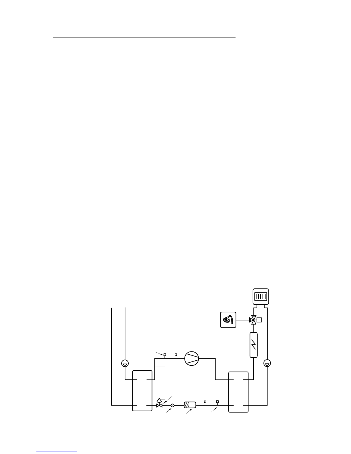
This is how your heat pump works:
Heat pump technology
The compressor, which is driven by an electric motor, forces the refrigerant into the heat pump
condenser as a gas at about 100°C. The gas and the water from the radiator system pass through the
condenser, which is a fully-welded stainless steel heat exchanger. When the hot gas is cooled by the
circulating water, it condenses (changes to liquid). As it does so, it provides energy for the heating
system or the hot water. After the condensor, the refrigerant, which is now in liquid form, continues
through a drying filter and a tank. The filter collects any moisture in the system and the tank is used as
an expansion vessel for the refrigerant to ensure there is always the correct amount in the condenser.
After the filter, the refrigerant passes through a sight glass. The sight glass is used to check the amount
of refrigerant in the system. In normal operation there should be no bubbles in the sight glass. However, bubbles may appear for short periods, mainly on rapid changes between hot water and radiator
operation and when the heat pump starts or stops.
After the sight glass the refrigerant goes to an expansion valve. The valve acts as a flow restrictor
between the high and low pressure sides of the system. The valve, which has a sensor (bulb) just
before the compressor, releases the right amount of liquid into the next heat exchanger, the evaporator.
In the evaporator, the liquid meets the circulating heat transfer fluid coming from the energy source in
the ground or bore hole. In this process, the liquid turns to gas (evaporates) under low pressure, which
uses heat. The heat is extracted from the the ground or bore hole free of charge.
After passing through the evaporator, the refrigerant is once more in the form of a gas (vapour). The
expansion valve sensor constantly checks that the evaporator is performing optimally, in order to use
as much free energy as possible. The gaseous refrigerant then goes to the suction side of the compressor, where it is compressed again. This completes the refrigerant circuit.
To protect the heat pump, pressure switches are fitted on the high and low-pressure sides of the system. These shut down the heat pump if the pressure in the system reaches an abnormal value. This is
dealt with in more detail in the section on troubleshooting.
Rock/Ground/Lake
Heating system
Hot water 3-way valve
(not D)
Pressure switch
Heat
transfer
fluid
pump
Compressor
Immersion
heater
(not D)
Evaporator
Heat
transfer
pump
Sight glass
Expansion valve
Pressure switch
CondenserFilter
Page 7
8
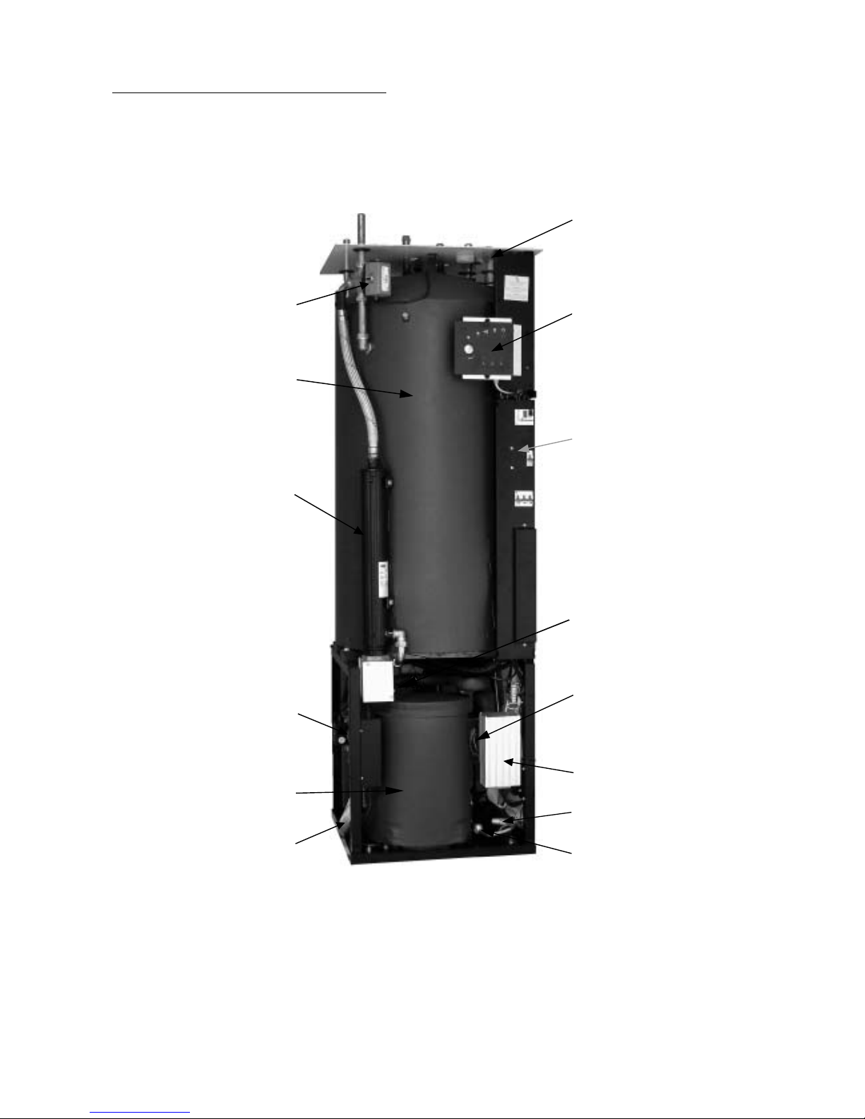
C series components
Please note: The picture shows a 1-phase unit.
3-way valve that switches
between heating and
domestic hot water.
Double-shelled
hot water heater.
Immersion heater.
Reset button for overheat
protection on the immersion heater.
Circulation pump on
the hot side.
Flexible hoses on the hot side
for vibration free operation.
Frequency adapted sound-
proof cover on compressor.
Electrical connection.
Control panel with large
display.
Enclosed electrical box
with motor protection
reset and circuit breaker
for heat pump and immersion heater.
Control unit Rego600.
Insulated corrosion
protected circulation
pump for the heat transfer
fluid system.
Expansion valve.
Sight glass.
Page 8
9
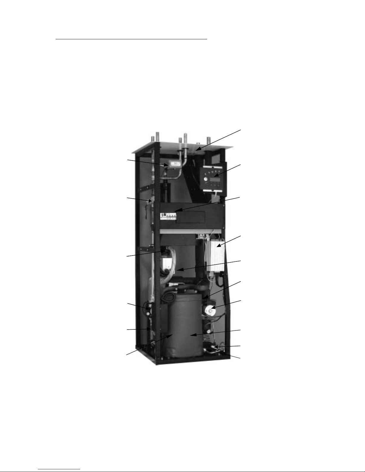
D and E series components
Please note: The picture is of the E series, 1-phase.
The D series has two connections on the hot side and does not include a 3-way valve and immersion
heater. The particle filter is supplied separately and is mounted outside the heat pump.
3-way valve that changes
between heating and
domestic hot water.
Cleanable particle
filter with cut-off.
Immersion heater.
Reset button for overheat protection on the
immersion heater.
Circulation pump
on the hot side.
Flexible hoses on the
hot side for vibration
free operation.
Frequency adapted
soundproof cover.
Electrical connection.
Control panel with
large display.
Enclosed electrical box with
motor protection reset and
circuit breaker for heat pump
and immersion heater.
Control unit Rego600.
Heat exchanger.
Insulated corrosion protected
circulation pump for the heat
transfer fluid system.
Compressor.
Expansion valve.
Sight glass.
Page 9

10
Principle
Principle of heating and hot water control
Your heat pump is fitted with a Rego600 control unit to guarantee you maximum savings and many
years of service. The unit, which has advanced monitoring functions, controls the heating and hot
water in your home. This ensures that all vital functions are monitored and that, if problems arise, the
heat pump is shut down before it is damaged.
When the heat pump is not able to meet the heating requirements, additional heat is connected that
together with the heat pump provides the required temperature. The Greenline C and E series has a
built-in immersion heater that can be connected in three steps. Factory setting is 2/3 electrical output.
The additional heat only provides the output that the heat pump cannot generate and in this way can
never take over heating the house completely. When the heat pump is once more able to meet the
heating demand, the additional heat is automatically switched off. An oil-fired boiler is normally used
to provide additional heat for the Greenline D series. In which case Rego600 controls the oil-fired
boiler and the existing mixing valve.
The heat pump is connected to the heating system’s return flow. The water is heated in the heat pump
and is then fed back to the heating system. While the heat pump is heating the water in the immersion
heater, the heating system is disconnected temporarily through the 3-way valve. A sensor in the hot
water cylinder makes sure that priority is always given to heating the hot water. When the water in the
cylinder reaches the required temperature, heat is once more supplied to the heating system.
Power failure
If the power supply fails, the control unit remembers all its settings and re-starts the heat pump when
the power returns.
Three different operating modes
The control unit can be used for three different operating modes: A, B and C. Please note that the C
series can only utilise operating mode A. The three operating modes are also outlined under Installer.
Operating mode A (C, D and E series)
This is the factory set operating mode based on an outdoor sensor that sends signals to the heat pump
control unit and controls it through an adjustable control curve. Water heating takes priority over
space heating. As well as operating the heat pump, Rego600 can also regulate other heat curves with a
mixing valve, e.g. through a combination of radiator and floor heating systems. An immersion heater is
used for additional heat.
Operating mode B (D series only)
Used when additional heat is from an oil-fired boiler. Operation is the same as for operating mode A.
Rego600 cannot control other heat curves in this operating mode.
Operating mode C (D series only)
Used in exceptional cases, it does not provide optimal operation for the heat pump because it always
works with a high temperature, or Fixed Temperature. This is most commonly used together with
existing electric boilers. This mode of operation is based on the existing electric boiler’s heater being
kept warm by the heat pump and by utilising the existing immersion heater in the boiler.
Page 10

11
Controls
The control unit operates the heat pump in three ways. We call them Curve Control, Room Sensor and
Fixed Temperature. Below follows a brief description.
Curve control (operating modes A and B)
This is the most common mode and is also the factory setting. This means that the heat pump adjusts
the heat in the house based on the outdoor temperature so that the radiator temperature increases as the
outdoor temperature reduces. An outside sensor sends signals to the control unit, which automatically
adjusts the supply of heat to the radiators. To set the temperature of a radiator for a certain outdoor
temperature, you can choose between a number of different curves on the control unit. This maximises
savings, since the heat pump never needs to work at a higher temperature than necessary. The heat
pump only delivers the maximum temperature when heating the hot water. Normally, hot water heating
accounts for 20% of the total annual requirement.
Room sensor (operational modes A and B)
A room sensor can be connected to the heat pump. It sends signals to the control unit and in this way
affects the curve control. The amount of affect the room sensor has on the curve control can be set on
the control panel. The room sensor is normally only used in combination with an outdoor sensor; when
a fan-assisted radiator is used in houses with electric radiators or a fire place, or in houses that are
wind sensitive.
Fixed temperature (operating mode C only)
This control technique is rarely used, and does not offer optimum savings from the heat pump. The
principle is that the heat pump is switched on and off by the built-in return sensor and always works
up to its maximum working temperature. The most common use for this control technique is when
there is a relatively new electric boiler and the heat pump is connected to it. The heat pump heats the
hot water cylinder in the boiler, and any additional heat required is provided by the boiler’ immersion
heater. There are unfortunately not many electric boilers on the market that are suitable for use in
conjunction with a heat pump.
Page 11

12
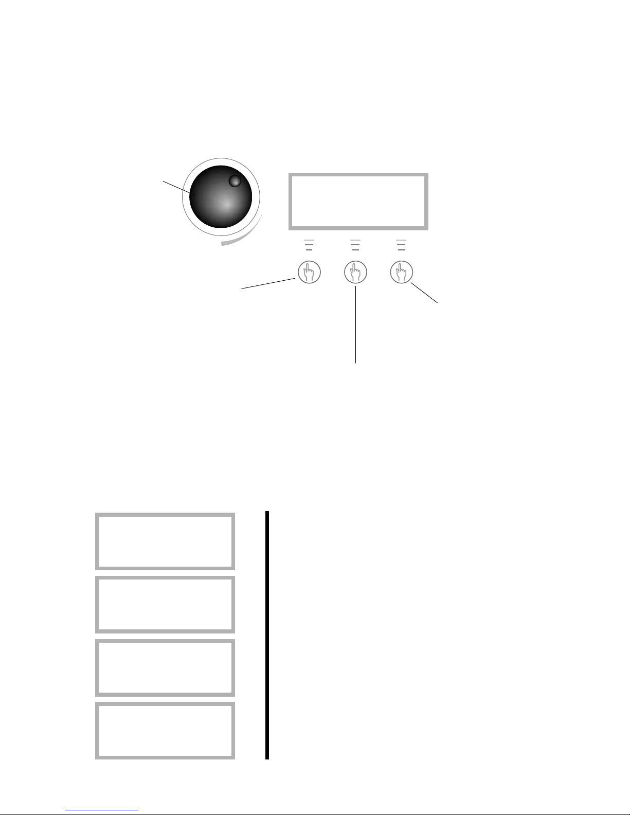
Control panel
Control panel buttons and displays
The control panel is the heart of your heat pump installation. From the control panel, instructions are
sent to the Rego600 control unit, which ensures that the house is uniformly heated. All settings are
carried out here and the display shows the settings that have been set.
Rego600 K1
020301 12.00.00 Fr
Heat Info Menu
The heat pump is in
operation when this
lamp is lit.
This lamp is lit when
the heat pump needs
additional heat.
This lamp is lit when
hot water is being
heated. It blinks during
hot water peaks and
additional hot water.
This lamp blinks when
a fault has occurred.
This switch is used to
turn the heat pump on
and off. The heat pump
is in operation when
the lamp is lit. The heat
pump is off when it
blinks.
This shows you
which user level
you are in.
This display
shows information
such as text and
temperatures.
Press once to come to
the complete menu for
settings and temperatures.
Press once for
continuous information about operation
conditions for the heat
pump and additional
heat.
Press once for a short
cut to the heat
settings.
This knob is used
to navigate the
menu and to
change settings.
Page 12
13
How to use the control panel
With three buttons and a knob you can navigate to the various displays for settings and readings. The
last line at the bottom of the display contains information about the functions of the buttons in the
current display. If you choose Heat or Info the display you have chosen to stay in will always remain.
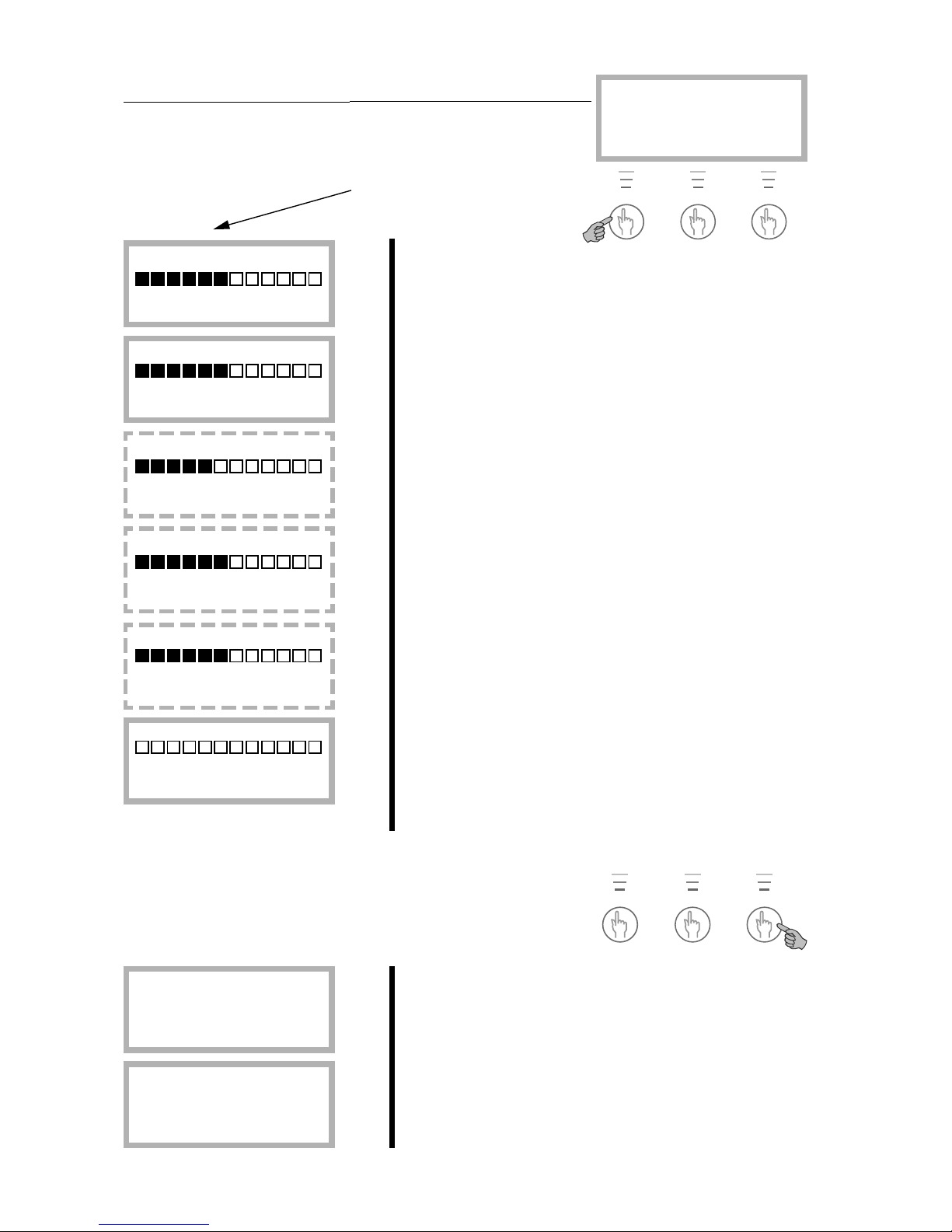
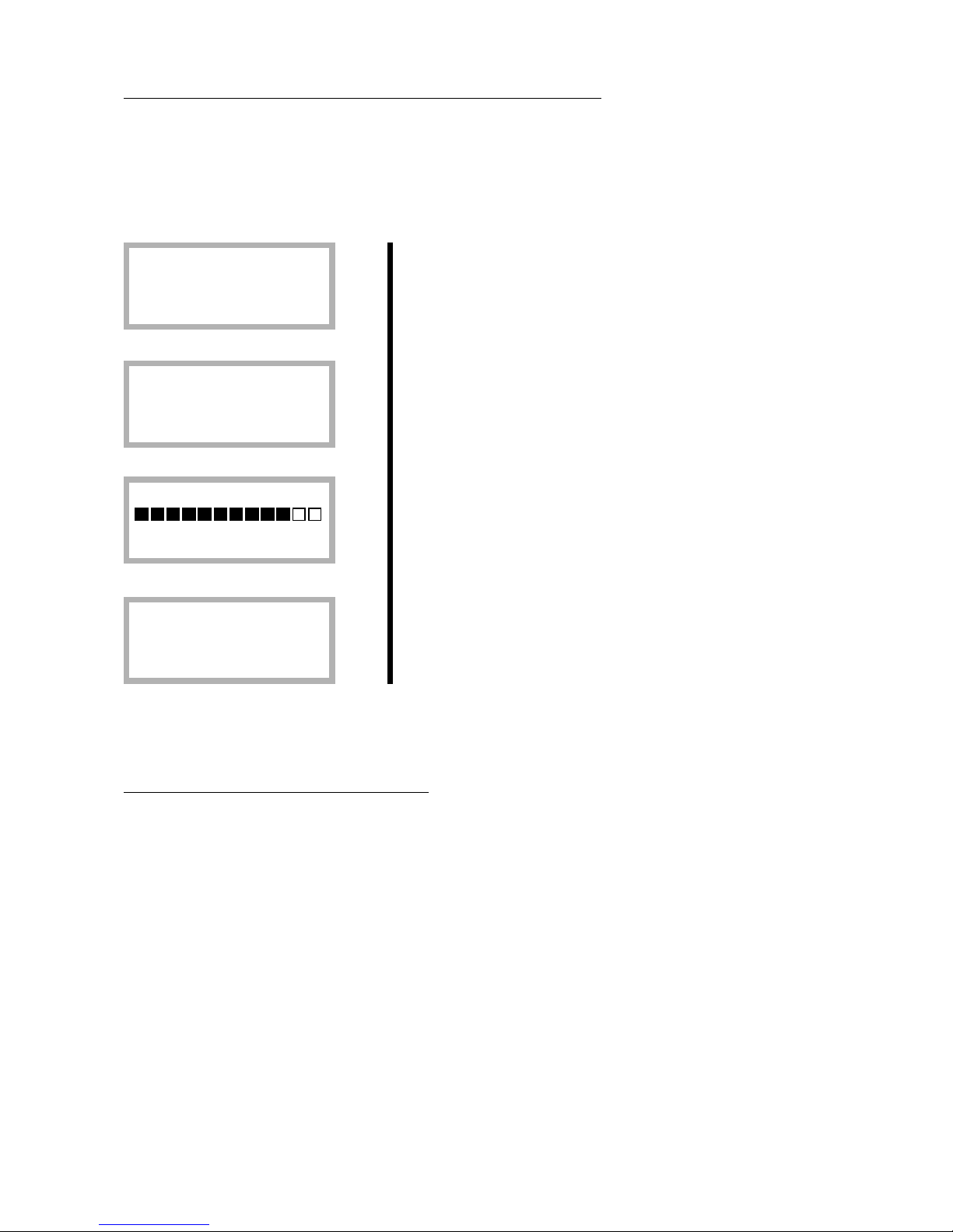
Examples of scrolling information
Here are some of the displays you see if you choose scrolling information with the Info button:
Heat pump is not operating.
The heat pump is producing hot water and you see the
current temperature and the temperature it stops at.
The heat pump and additional heat is in operation.
A need for heat has arisen and the heat pump is waiting for
the reset time to count down to zero.
STANDBY
No rad heat required
No hotwater required
HOT WATER MODE
Heat pump only
Stop temp 47.5°
Present temp 42.0°
HEAT RAD MODE
Compr. + Add. heat
Stop temp 45.0°
Present temp 44.0°
HEAT RAD REQ
Heat pump starts
in 320 seconds
Press “Heat” once and
you come to the shortcut
for heat settings. You can
choose to stay in which
display you want.
Press “Info” once and you receive continuous information about what
the heat pump is doing and at which temperature it stops. You can
choose to remain in this display and always receive this information.
Press the middle button again to return to the first display.
Press “Menu” once and
you come to the main
menu for settings or
temperature readings.
With the knob
you navigate up
and down between the displays or change
the settings.
Rego600 K1
020301 12:00:00 Fr
Värme Info Meny
Page 13
14
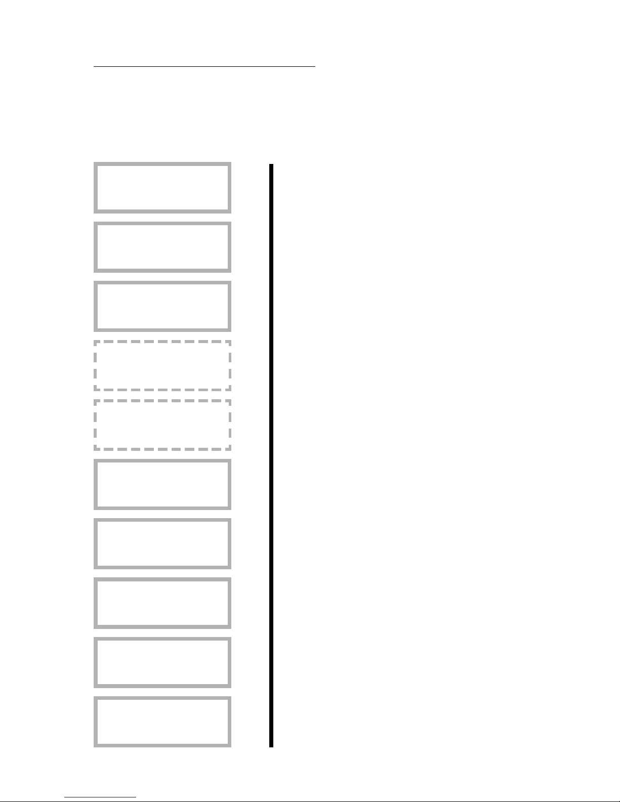
Basic functions (at customer level 1)
Heating and extra hot water
Press Heat to come to the short cut to the heat settings. These displays
are then available.
House heating settings in areas 0 to 10. See more detailed
description in Heat Settings chapter.
Fine adjustment settings in areas -10 to +10. See more
detailed description in Heat Settings chapter.
Here you can set the heat in areas 0 to 10 if you use an extra
heat curve with a mixing valve.
Here you set the fine adjustment of the mixing valve curve
in –10°C to 10°C.
If a room sensor is connected you can set the required room
temperature here. At customer level 2 you can set how
much you want the sensor to affect the heating system.
You can temporarily increase the hot water temperature
with the electric water heater here. The heat pump first
increases it to around 50° and then the electric water heater
to around 65°. The electric heater starts again at 60° and
increases the temperature to 65° in set time. The area is 148 hours and when the set time has passed, the normal
operation is resumed.
Temperatures
Press “Menu” to come to the main menu. Where you can also
carry out heat settings and see the temperatures. These
displays are then available.
The radiator temperature settings you make in the short cut
to Heat you can also make in line 1 and hot water setting in
line 2.
In line 3 you can see all the temperatures where sensors are
connected.
With
extra
sensor
only
With
extra
sensor
only
With
extra
sensor
only
Operating
mode A
only
Extra DHW:
1hr 20hrs 48hrs
Return Adjust
Room temperature
10° 20° 30°
Return Adjust
Mix. valve fine-tune
-10° 0,0° 10°
Return Adjust
Mix. valve incr/decr
0 4 10
Return Adjust
Temp. fine-tune
-10° 0,0° 10°
Return Adjust
Temp. incr. / decr.
0 4 10
Return Adjust
Main menu
Monitor all
temperatures 3
Return Select
Main menu
Indoor temperature
settings 1
Return Select
Rego600 K1
020312 12.00.00 Ti
Heat Info Menu
Page 14
15
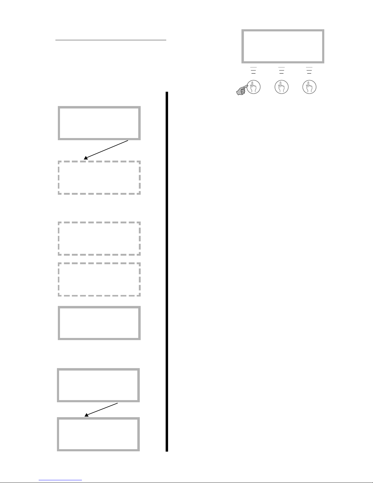
Enhanced functions
As user you have access to extra functions. Keep the Heat button
pressed down for five seconds and go into Menu to gain access to
these displays. You will automatically return to level 1 again after
30 seconds.
Keep the button pressed down for 5 seconds.
You have pressed Menu and are on row 1. Press “Select”
and turn the knob and the displays scroll up. You can then
choose to enter the display you require. Each display has a
number.
With a room sensor installed you can set the value of how
much you want it to affect the outdoor sensor. A high value
gives more affect from the room sensor. Please note the
room sensor only fine tunes the heat curve. It is therefore
important that you set the basic settings for the heat curve
and fine tuning from the start.
If a room sensor is installed you can set the number of days
that the room temperature is lowered to 15°C here. The
temperature is not adjustable and it does not affect the hot
water. Normal operation is resumed when the period is
over.
If a room sensor and remote control is installed you can set
the required room temperature here. You can then use the
telephone to increase the temperature to normal.
This equipment is available as an accessory.
At this set temperature the heat pump only produces hot
water.
Line 1
Only
with
extra
sensor
and at
operating
mode A
only
With extra
sensor
only
With extra
sensor ,
remote
control
and at
operating
mode A
only
At
operating
modes A
and B
only
At
operating
mode A
only
Using the knob you have moved to the hot water settings in
row 2.
Setting for intervals for the continual raising of the hot
water temperature. If you choose for example7 days, the
temperature is raised using the electric water heater once a
week to around 65°C (Operating mode A with electric
water heater only).
Line 2
Hot water setting
Interval for
hot water peak 2.2
Return Select
Main menu
Adjusting the hot
water settings 2
Return Select
Temperature settings
Setting of summer
disconnection 1.14
Return Select
Temperature settings
Remote control
temperature 1.13
Return Select
Temperature settings
Setting of holiday
function 1.12
Return Select
Temperature settings
Setting of room
sensor infl. 1.11
Return Select
Main menu
Indoor temperature
settings 1
Return Select
Rego600 K2
020312 12.00.00 Ti
Heat Info Menu
Page 15

16
Line 4
You have now moved to timer control settings line 4.
Here you can set the times day for day that you want to
utilise the clock settings. You can set all the weekdays
independent of each other. Press “Select”.
The example describes how you set Monday between 22:00
and 06:00. Press “Adjust”.
There is now a cursor under Monday. Turn the knob and mo
becomes Mo. Monday is now activated.
Now set the clock setting for between 22:00 and 06:00 in
the morning. Press the right arrow button until the cursor is
under the first 00. Turn the knob until 22:00 appears. Press
the button twice more (the cursor moves two steps to the
right) and turn the knob until 06:00 appears. Press the right
arrow button once more and the arrow is replaced by Save.
Press “Save” to set the timer controls.
You can now do the same for all the other days of the week
you want to timer control. Use the knob in this display to
come to the other days.
In display 4.1.1 you set how much you want the temperature
to be raised or lowered in the above time zone settings. If
you choose for example -5°C, the heating system temperature is lowered by 5°C.
In display 4.3 you can disconnect the hot water completely
during e.g. peak rate times. This is done in the same way as
with the heat pump time controls.
Not
operating
mode C
Clock setting
Clock setting DHW
accord. to clock 4.3
Return Select
Clock setting
Setting level
heat pump +/- 4.1.1
Return Select
Clock setting HP 1
Mo 22:00-06:00
Return Adjust
Clock setting HP 1
Mo 22:00-06:00
^^
Cancel <- ->
Clock setting HP 1
Mo 00:0000:00 ^^
Cancel ->
Clock setting HP 1
Mo 00:00-00:00
Return Adjust
Clock setting
Clock setting HP
accord. to clock 4.1
Return Select
Main menu
Timer control
settings 4
Return Select
Page 16

17
Line 7
Not
operating
mode C
In line 7 you can read the running times for the heat pump
and additional heat. Press “Select” to enter these menus.
Here you can see how many hours the heat pump has been in
operation.
This shows the distribution of the heat pump between hot
water and heating in percentage.
Here you can see how many hours the additional heat has
been in operation.
This shows the distribution of the additional heat between
hot water and heating in percentage.
You can set the clock to the correct time if it is wrong.
Line 11 shows a record of the alarms that may have occurred
on your heat pump. You can see the type of alarm and when
it occurred. An * in the display means the alarm is still
active.
If you want to change your settings at customer levels 1 and
2 you can return to factory settings on line 12.
Please note: If you at the level for installer/service when you
choose factory settings, the installer must carry out a new
start-up of the plant with new settings. The installer/service
level is for installer only. As end-user you must never go into
this level!
Not
operating
mode C
Line 10
Line 11
Line 12
Main menu
Return to
factory settings 12
Return Select
Main menu
Alarm logging
of all alarms 11
Return Select
Main menu
Clock, setting
time and date 10
Return Select
Op. time readings
Distribut. add. heat
DHW-Rad in % 7.4
Return Select
Op. time readings
Add. heat in operat.
number of hours? 7.3
Return Select
Op. time readings
Distribution HP
DHW-Rad in % 7.2
Return Select
Op. time readings
Heat pump in operat.
number of hours? 7.1
Return Select
Main menu
Op. time readings on
HP and add. heat 7
Return Select
Page 17
18
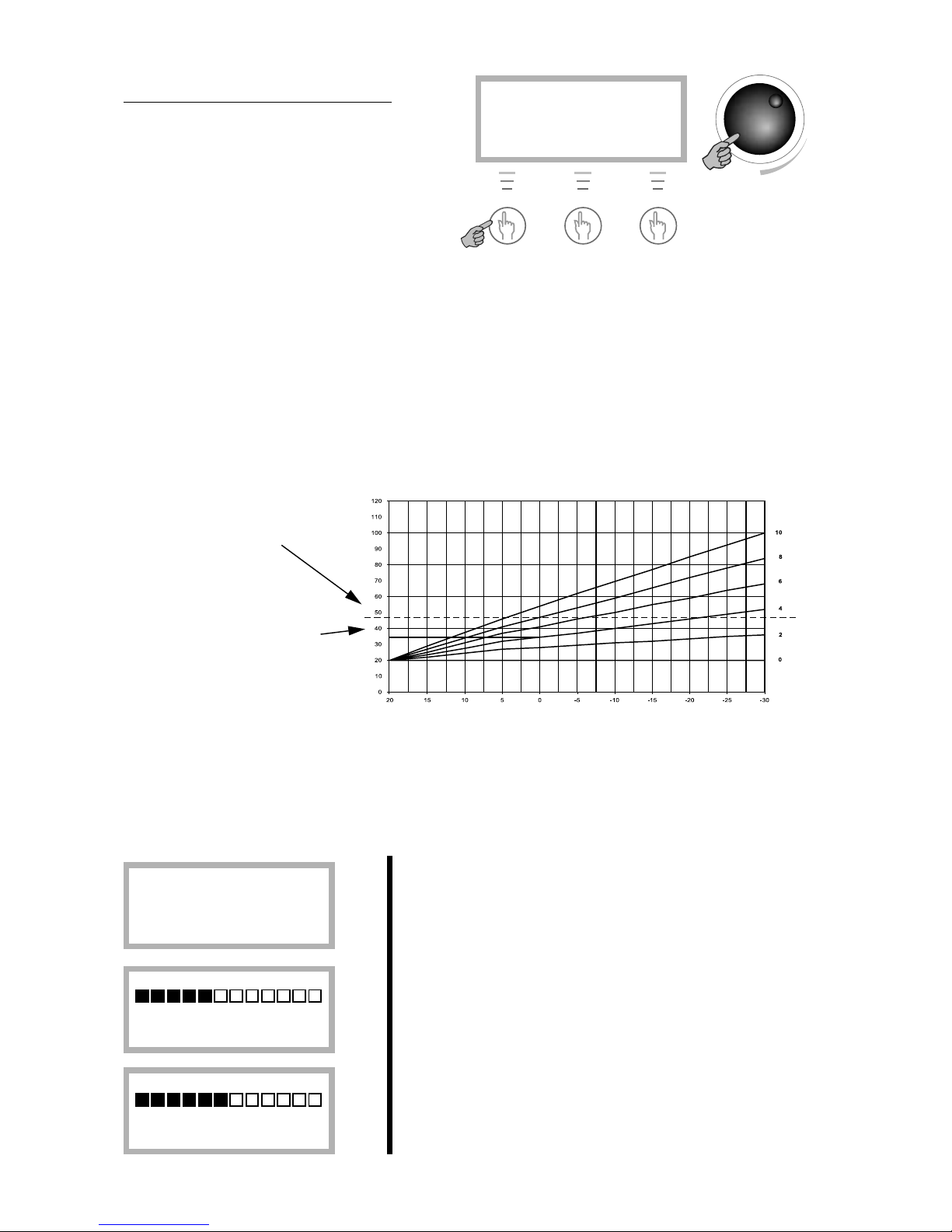
Setting the heating
In the Temperature increase/decrease display
you use the knob to change the heat curve.
The lines show how the return temperature
varies with the outdoor temperature for
different settings. The colder the weather the
warmer the heating system. Curve 4 is the
factory setting and in the example you can see
that this gives a return temperature of around
35
o
C at an outdoor temperature of 0oC.
The example describes how to change the heat curve in the Heating increase/decrease menu.
Please note that a high value could cause the heat pump to stop if the return temperature is too high.
Heat curve
Radiator return
temperature
Setting
Outdoor temperature
The appearance of the heat curve
The limit for when the
heat pump stops for too
high a return temperature.
The line shows that if heat
curve 4 is chosen, the heat
pump stops at around 35
o
C
when the outdoor temperature
is 0
o
C.
Cold weather:
If the indoor temperature is too low or too high during cold
weather, you use Temp. incr./decr. to change it.
Press “Heat”.
The set value is shown in the display. In the shape of a bar
but also as a digit. The area is between 0 and 10. Press
“Adjust”.
Turn the knob to the right to increase, to the left to decrease.
The example shows how you increase the value to 5. Turn
the knob until 5 appears in the display. The new value now
appears in the display. Press “Save” to save the new value.
Rego600 K1
020312 12.00.00 Ti
Heat Info Menu
Temp. incr. / decr.
0 4 10
Return Adjust
Temp. incr. / decr.
0 5 10
Return Save
Rego600 K1
020312 12.00.00 Ti
Heat Info Menu
Please note that the flow temperature is then around 7-10oC warmer. During the first winter, the heat
curve must be set up so that the temperature in the house is pleasant whatever the weather. The heat curve
should preferably be adjusted at a low temperature under 3
o
C. You should wait two days after adjusting
before carrying out any readjustments. Also note that a lower curve setting gives a lower runnig cost.
Page 18
19
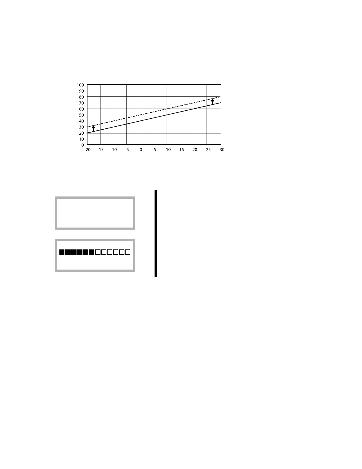
Warm weather:
If the indoor temperature is too low or too high during warm
weather, you use fine tuning to change it. You come to
“Temp. fine-tune” by pressing “Heat” and turning the knob
to the right.
Fine tuning can be set in areas –10°C to 10°C. You change
the fine tuning in the same way as “Temp. increase/decrease” as described on the previous page.
The heat curve can also be fine tuned. You do this in the Temp. fine tune display. The dotted line illustrates how the parallel offset has been turned towards plus. The entire curve moves upwards, in contrast
to increasing the slope, when only the slope changes.
Rego600 K1
020312 12.00.00 Ti
Heat Info Menu
Temp. fine-tune
-10° 0,0° 10°
Return Adjust
The dotted line illustrates
how the fine tuning adjustment has been turned
towards plus.
Fine tuning adjustment
Radiator return
temperature
Outdoor temperature
Page 19
20
Fixed temperature (D series only)
If the heat pump is set at operating mode C with a fixed temperature, then it can only be engaged and
disengaged by the built-in return sensor. There are two displays available for this mode. Please note
that if a mixing valve is connected to the heat pump, the Temp. incr/decre and Temp. fine tune displays
control the settings for the mixing valve opening to the heating system.
To adjust the engaging and disengaging temperature, press
“Menu” followed by “Select”. You are now in line 1.
Use the knob to navigate to display 1.16 and press “Select”.
The factory setting is 48°C. Please note that this concerns
the return temperature to the heat pump. The temperature
from the pump is normally 5-10C higher. Settings above
48°C are not allowed for technical reasons.
You can also set the difference between starting and
stopping the heat pump in display 1.17. The factory setting
is 5°C. A lower setting gives more frequent starts and stops
for the heat pump. Press “Select” to adjust.
Simple tips for saving
The lower you can keep the temperature of the radiators in the house, the better your heating economy
will be. So take make sure not to set your heat curve too high. Operate your heating system as efficiently as possible by making sure that the entire surface of your radiators or your underfloor heating
coils are kept hot.
Thermostatic valves on your radiators or underfloor heating may have a negative effect on your
heating system because they restrict the flow so that the system has to compensate with a higher water
temperature. If thermostat valves are fitted, they should be fully opened, except in bedrooms, where
they can be turned down slightly.
Temperature settings
Return thermostat
stop temp sett. 1.16
Return Select
Return thermos. stop
30° 48,0° 50°
Return Adjust
Temperature settings
Return thermostat
hysteresis set 1.17
Return Select
Rego600 K1
020312 12.00.00 Ti
Heat Info Menu
Page 20
21
All sensor temperatures
Below are the various sensor temperatures that are visible under line 3 in the control panel. Note that
not all the sensors are standard but are available as accessories for different areas of use. To get there
press ”Menu” in the control panel and then turn the knob to line 3. Then press ”Select”.
Shows the temperature of the heating system return flow.
This varies depending on the outdoor temperature.
Shows the outdoor temperature.
Shows the temperature in the outer container of the electric
water heater’s bottom part. This temperature is around 5°C
lower than the temperature in the hot water tank.
If an extra mixing valve is used for e.g. floor heating then
the flow pipe is visible on the circuit. It varies with the
outdoor temperature.
If a room sensor is used, you see the temperature of the
room where the sensor is located.
The sensor shows the working temperature of the compressor. It varies between around 70°C and 125°C.
The sensor shows the outgoing temperature from the heat
pump. It varies depending on the outdoor temperature and if
the heat pump is in hot water production mode.
The sensor shows the ingoing temperature to the heat pump.
It varies as mentioned above. Please note that for safety
reasons the heat pump stops when this shows a temperature
of more than 48°C.
The sensor shows the temperature from the bore hole or the
ground. It normally varies between -5°C and 8°C throughout
the year.
The sensor shows the temperature to the bore hole or the
ground. It is normally 1.5°C till 5°C lower than heat transfer
in.
Line 3
Standard
Standard
Only in Cserie
Accessories
Accessories
Standard
Standard
Standard
Standard
Standard
Temperature readings
Return radiator GT1
Off ##,#° Now ##,#°
Return
Temperature readings
Out GT2
###,#°
Return
Temperature readings
Hot water GT3
Off ##,#° Now ##,#°
Return
Temperature readings
Shunt, flow GT4
Tgt ##,#° Now ##,#°
Return
Temperature readings
Room GT5
Tgt ##,#° Now ##,#°
Return
Temperature readings
Compressor GT6
###,#°
Return
Temperature readings
Heat trfluid out GT8
###,#°
Return
Temperature readings
Heat tr fluid in GT9
###,#°
Return
Temperature reading
Ht trfld(coll)inGT10
###,#°
Return
Temperature reading
Httrfld(coll)outGT11
###,#°
Return
Page 21
22
If something is wrong
The control unit provides a lot of information about faults and how to remedy them. The control unit
incorporates advanced functions to monitor and protect your heat pump. This means there is no risk
involved in resetting an alarm. If a fault persists, you should contact the installer.
Alarm examples and what to do
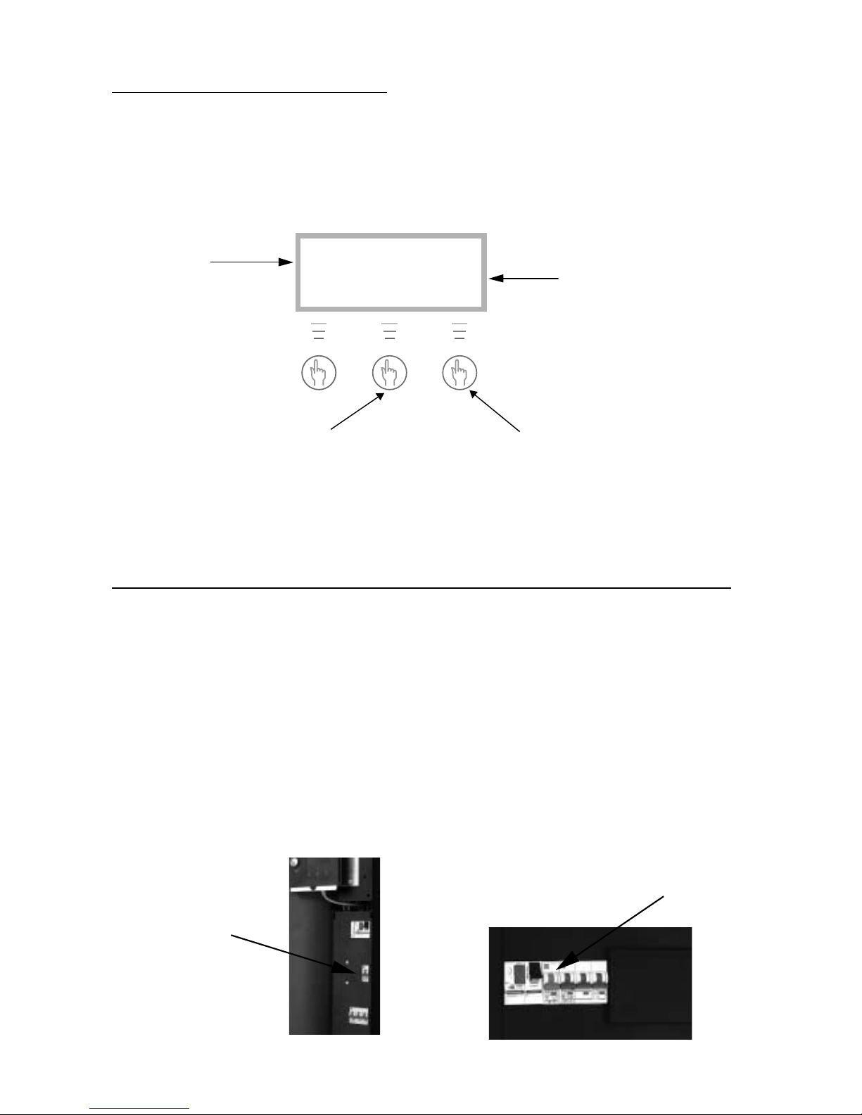
If the control panel is dark
Possible faults:
• The fuses or MCBs (miniature circuit-breakers) in your fuse box.
This is what to do: Check the fuse (or MCB) for your heat pump. If the small plate at the bottom of
the fuse has come off, the fuse has blown and must be replaced. If you have MCBs, and they have
tripped, move the switch to the up position.
Note that the heat pump cannot restart until after 15 minutes. This delay is needed for technical
reasons!
• If the heat pump MCB has tripped, this is what to do:
Press ”Ackn” and the fault is remedied,
the alarm lamp goes off and the heat
pump starts again within 15 minutes. If
the lamp is lit with a steady glow then
the alarm is remedied but the fault
remains. If several alarms have triggered, use the knob to navigate to them.
If you press ”Info” and then turn
the knob you will see information about the possible causes
and how you can remedy the
fault yourself.
ALARM
Power failure
020312 16.08.15
Info Ackn.
Time and date for when the
fault occurred.
Cause
On D and E series:
Reset by pushing the
toggle to the up position.
The C series
Reset by pushing the
toggle to the up position.
Page 22

23
All alarms
Below is a description of the alarms that can appear in the menu display. The description gives an idea
of what the fault is and what you yourself can check and remedy. An alarm can sometimes occur
temporarily so there is never any risk with resetting it. If a fault persists, you should contact the
installer.
The description sometimes refers to a heat pump component. Pages 28 and 29 have details of where to
find the components.
COMPRESSOR MOTOR CUTOUT SWITCH ALARM
To reset the alarm:
Reset the motor cutout by pressing in the black button (position
2) Then press ”Ackn”. NOTE: The lamp goes out even if the
motor cutout has not been reset. (Model C4 have built-in
temperature protection in the compressor that resets automatically when the temperature has reduced).
ALARM (MB1)
Compr. circ. switch
020312 16.08.15
Info Ackn.
Probable causes and actions:
• Sporadic fault or overloading of the power supply.
Action: Reset the motor cutout and wait and see. (Not model C4)
• The current setting of the motor cutout is too low. The compressor’s current intensity varies during
summer/winter operation. (Not model C4)
Action: Contact the installer.
• Contactor or cutout faulty, or loose electrical connections to the compressor.
Action: Contact the installer.
• Compressor faulty.
Action: Contact the installer.
ALARM (MB2)
HTF circ-pump switch
020312 16.08.15
Info Ackn.
HEAT TRANSFER FLUID CIRCULATION PUMP
SWITCH ALARM
To reset the alarm: Press ”Ackn”. (11 kW-models have built-in
motor cutout in the pump that resets automatically after a period
of time. The MB2-alarm is not shown in other models). Note
that the lamp goes out even if the motor cutout has not been
reset.
Probable causes and actions:
• The pump has stopped because of contaminants.
Action: If the pump has an air vent screw it can be loosened and the pump restarted with a screwdriver.
• Fault in the pump’s electric motor.
Action: Contact the installer.
• Temporary fault.
Action: If the fault persists, contact the installer.
Page 23

24
ALARM ON PRESSURE SWITCH LOW
To reset the alarm: Press ”Ackn”.
ALARM (LP)
Low pressure switch
020312 16.08.15
Info Ackn.
Probable causes and actions:
• Air in the heating system.
Action:Check the expansion vessel and fill if required. If air is heard continuously in the system,
contact the installer.
• Heat transfer pump has stopped or is set at too low a speed.
Action: Check the pump has not stopped or is set at the wrong speed.
• Particle filter on the cold side has clogged.
Action: Check the filter and clean if required.
• Not enough refrigerant in the circuit.
Action: Check that bubbles do not appear continuously in the sight glass. Contact the installer.
• Not enough antifreeze in the heat transfer circuit creating ice in the heat exchanger.
Action: Contact the installer.
• Expansion valve faulty (alarms occur at long intervals, about every three or four weeks).
Action: Contact the installer.
HIGH PRESSURE SWITCH ALARM
To reset the alarm: Press ”Ackn”.
ALARM (HP)
High pressure switch
020312 16.08.15
Info Ackn.
Probable causes and actions:
• Air in the heating system.
Action: Check the system and vent the radiators if necessary.
• Not enough flow over the heat pump.
Action: Check that the circulation pump has not stopped and that a valve in the system is not
shut.
• Hot side particle filter clogged.
Action: Check the filter and clean if required.
• Refrigerant circuit over-filled.
Action: Contact the installer.
• Drying filter clogged.
Action: Contact the installer.
Page 24

25
ALARM ON COMPRESSOR SUPERHEAT
To reset the alarm: Press “Ackn”.
Probable causes and actions:
• The working temperature of the compressor is too high.
Action: If the fault persists, contact the installer.
• Sporadic temperature rise due to abnormal operating conditions.
Action: Wait and see.
ALARM (GT6)
Compressor superheat
020312 16.08.15
Info Ackn.
PHASE SEQUENCE FAULT ALARM
(Only 3-phase units)
To reset the alarm: The alarm does not reset until the phase
sequence has been changed. Then the heat pump starts
automatically.
Probable causes and actions:
• Phase sequence to the heat pump is incorrect.
Action: The phase sequence to the incoming supply must be changed.
POWER FAILURE ALARM
To reset the alarm: The alarm resets itself and the heat
pump starts automatically when the fault has been corrected.
Probable causes and actions:
• One or two phases are missing to the heat pump.
Action: Check the fuse (or MCB) for your heat pump. If the small plate at the bottom has come loose
then the fuse is broken and must be replaced. If you have ciruit breakers that have tripped, reset by
pushing the switch upwards.
ELECTRIC WATER HEATER ALARM
To reset the alarm: Reset water heater’s MCB (pos 4) or
overheat protection (pos 5). Press “Ackn”.
Probable causes and actions:
• The electric water heater MCB has tripped
Action: Reset the MCB by pushing the switch upwards. If the MCB trips again then the water heater
is probably faulty, contact the installer.
• The electric water heater overheat protection has tripped
Action: Reset by pressing the button on heater’s protective cover until it clicks. It could depend on a
bad flow over the heater caused by the circulation pump standing still or clogged particle filter. Check
the filter and circulation pump.
ALARM (EK)
Electrical cassette
020312 16.08.15
Info Ackn.
ALARM
Power failure
020312 16.08.15
Info Ackn.
ALARM
3-phase incorrect
020312 16.08.15
Info Ackn.
Page 25

26
ALARM, HIGH RETURN TO THE HEAT PUMP
To reset the alarm: The alarm resets itself and the heat pump
starts automatically when the temperature has dropped.
ALARM (GT9)
High return HP
020312 16.08.15
Info Ackn.
Probable causes and actions:
The heat pump has a sensor that stops the heat pump for safety reasons when the return temperature is too
high, about 48°C.
• The temp. incr/decr knob is set so high that the heating system return temperature goes too high.
Action: Reduce the temp. setting.
• The hot water temperature is set too high.
Action: Contact the installer.
• The radiator or underfloor heating system valves are closed.
Action: Open the valves.
• The flow across the heat pump is greater than the flow in the heating system.
Action: Reduce the speed of the circulation pump in the heat pump or increase the speed of the
mainpump in the heating system. Contact the installer.
SENSOR ALARM
To reset the alarm: The alarm resets itself and the heat pump
starts automatically when the fault has been corrected.
ALARM (GT1)
Sensor return rad.
020312 16.08.15
Info Ackn.
Probable causes and actions:
Alarm if a sensor fault can be indicated for all sensors that are connected to the heat pump. The example
shows the alarm for the Return radiator, GT1 sensor. The principle is the same for all sensor alarms.
• Temporary fault.
Action: Wait and see.
• Short circuit or disconnected to sensor.
Action: If you have an instrument that can measure resistance, you can check the resistance of the
circuit and compare with the table for sensors in Technical spec. If not, contact the installer.
• Faulty sensor or faulty connection.
Action: Contact the installer.
HEAT TRANSFER FLUID SYSTEM OUT MAX ALARM
To reset the alarm: The alarm resets itself and the heat pump
starts automatically when the temperature has dropped.
ALARM (GT8)
Heat tran. fluid out
020312 16.08.15
Info Ackn.
Probable causes and actions:
The heat pump has a sensor that stops the pump for safety reasons when the outgoing temperature is too
high at around 75
o
C.
• Not enough flow over the heat pump.
Action: Check that the circulation pump has not stopped and that a valve in the system is not closed.
• Hot side particle filter clogged.
Action: Check the filter and clean if required.
Page 26

27
Maintaining your heat pump
Your heat pump normally requires little maintenance, but we recommend occasional checking to ensure
that your heating installation give the best possible performance. The description sometimes refers to a
heat pump component. You find these on the following pages.
Working on the heat pump
• Switch off the electrical supply before commencing work on the heat pump. Usually there is an
isolating switch on the wall before the heat pump.
• Only an accredited refrigeration company is permitted to work on the refrigerant circuit. The installa-
tion contains gases that may form toxic fumes when combined with discharges and naked flames. The
gas that forms may cause choking even at low concentrations. If it should leak, evacuate the room
until it has been thoroughly aired.
Normal maintenance
Points to check a few times a year:
• Sight glass (pos 6). When the heat pump starts, and during rapid temperature changes, you can
sometimes see bubbles in the liquid in the refrigerant circuit for a minute or so. This is normal.
If there are always bubbles in the sight glass: Contact the installer.
Sight glass
• Expansion vessel. A plastic expansion vessel is connected to the heat pump heat transfer fluid
circuit. The level of the vessel must not fall below1/3 (the vessel is mounted outside the heat pump).
Too low fluid level: With the pump working, remove the lid to the valve at the top of the vessel and open
the valve. Fill with antifreeze or clean water (simplest with a watering can). Shut the valve again and
screw on the lid.
Ball valve with lid
• Particle filter (pos 1, only built-in in the E series on the hot side). The particle filter, which is con-
nected on both the hot and cold sides of the heat pump protect the heat exchangers from dirt. Some-
times these filters may get clogged and cause malfunctions.
Do this when checking: Shut down the heat pump with the on/off button on the control panel. Close the
valve and unscrew the sealing cover. Check for dirt in the filter. If necessary, remove the circlip that
retains the filter. The simplest way to do this is by using pliers. Remove the filter and flush it clean with
water. Refit the filter, circlip and cover. Open the valve and start the heat pump. Note that the particle
filter in the E series is mounted inside the heat pump. On the cold side and in the C and D series the
filters are outside the heat pump.
Particle filter
Page 27

28
The various parts in the C series
Please note: The picture shows a 1-phase unit.
Control safety anode
(Only for models with stainless hot water cylinder)
At the top of the hot water cylinder, under the insulation, there is an electronic protection anod (standard
feature) Its purpose is to prevent corrosion. The cylinder must be full of water for the anode to work.
If the heat pump is equipped with a magnesium anode, the anode can corrode depending on the water
quality. If its diameter has been reduced to a minimum it must be replaced. This is how you check the
magnesium anode:
1. Shut off the main cold water feed.
2. Turn on a tap to reduce the pressure in the water cylinder.
3. Unscrew the anode and check it.
If the anode is electronic there is a control panel with LEDs where you can see the status of the anode. It
shows a red or a green light. If the LED shows green, the anode is operating and working normally. If
large amounts of hot water are drawn off (when filling a bath for instance) the LED may show a red light
for a short time even though there is no fault. If the LED shows red for more than 10 hours, the anode is
faulty and a service engineer must be called.
Electronic anode Control panel with LEDs Magnesium anode
Pos 2
Reset, motor cutout
compressor.
Pos 3
Reset heat pump breaker
heat pump.
Pos 4
Reset circuit breaker
electric water heater.
Pos 5
Reset button for overheat protection on the
immersion heater.
Pos 6
Sight glass.
Page 28

29
The various parts in the D and E series
Please note: The picture is of the E series, 1-phase.
Pos 1
Cleanable particle filter
with cut-off
Pos 2
Reset, motor cutout
compressor.
Pos 3
Reset circuit
breaker heat pump.
Pos 4
Reset circuit
breaker immersion
heater.
Pos 5
Reset button for
overheat protection
on the immersion
heater.
Pos 6
Sight glass.
Page 29

30
What the shipment includes
Standard components
• heat pump unit with the necessary safety functions and electrical components
• factory mounted control unit Rego600. Rego600 can be used for simultaneous operation
together with an immersion heater or oil-fired or electric boiler with mixing valve.
• sensor radiator return, GT1 (packed separately).
• sensor hot water, GT3 (C series).
• sensor out, GT2 (packed separately).
• sensor, compressor, GT6.
• sensor heat transfer fluid out, GT8.
• sensor heat transfer fluid in, GT9.
• sensor heat transfer fluid (collector ) in, GT10.
• sensor heat transfer fluid (collector ) out, GT11.
• pump for heat transfer fluid and heat transfer circuits.
• built-in, flexible hoses on the heat transfer circuit.
• particle filter with shut off for heating and heat transfer fluid side (packed separately in C
and D series).
• expansion vessel and safety valve for heat transfer fluid circuit (packed separately).
• soundproof cover on compressor
Accessories
• sensor hot water, GT3 (D and E series).
• sensor flow duct mixing curve, GT4.
• room sensor, GT5.
General
Temperatures
Note that the heat pump can work to a maximum return temperature of around 48°C. Anything over
this and the heat pump stops for safety reasons. The maximum outgoing temperature from the heat
pump is around 55°C. A higher temperature can be achieved using an immersion heater.
Particle filter
The particle filter supplied must always be fitted in the input pipe of the hot side as close as possible
to the heat pump, and horizontally. The filter is mounted on the heat transfer side in the E series. The
filters is separately packed on the heat transfer fluid side.
Transportation
The heat pump must always be transported and stored upright and dry. The heat pump can be placed
on its back temporarily for moving into place of installation.
Positioning
Place the heat pump on a flat base and adjust the rubber feet until it is level. Avoid installing the heat
pump close to sensitive walls such as bedroom walls, since the pump produces a certain amount of
noise when running. The room must have a floor drain. Installation must comply with local construction regulations.
Page 30

31
Dimensions and connections, C series
Dimensions are given in mm
(1) Return radiator
(2) Riser radiator
(3) Cold water in
(4) Hot water out
(5) Heat transfer fluid in
(6) Heat transfer fluid out
Electrical
connections
Front
®®®
®
(1)
(2)
(3)
(4)
(6)
(5)
600
®®
®® ® ®
®
®
®
85 240 360 460 525
85
65
500
600
345
225
40
1770
Page 31

32
Dimensions and connections, D and E series
Dimensions are given in mm
(1) Return radiator
(2) Riser radiator
(3) Return DHWC
(4) Riser DHWC
(5) Heat transfer fluid out
(6) Heat transfer fluid in
The D series does not have
Pos. 3 and 4
Electrical
connections
Front
®®
®
®
®
(1)
(2)
(3)
(4)
(6)
(5)
105 310 505
600
600
510
349
294
239
1500
Page 32

33
Collector
Collector hose
The collector hose consists of a thin-walled plastic hose of make Pem 40 x 2.4 DN 6.3. Length and
depth as in IVT:s dimensioning program.
Install the hose rising towards the heat pump to avoid air pockets.
It is vitally important that the filling around the ground coil does not contain stones or other objects
that could damage the coil. The final filling is best carried out after the ground collector has been
pressure tested. Avoid chips or dirt getting into the coil when cutting.
Installation and filling around the collector hose must comply with local regulations.
Bending diameter
Minimum bending diameter permitted is 1 metre. Always use an elbow coupling for sharper bends. If
you damage the hose by bending it too sharply you can repair it with a pipe joint.
Maximal lengths
Specified pressure drop and hose lengths are based on heat transfer fluid containing 29 volume percent
ethanol. Other heat transfer fluids are not recommended because they give high pressure drop at low
temperatures. The table shows the maximum hose length for each heat pump model. The coils can be
parallel connected if the collector’s length exceeds that permitted for a circuit. Note that maximum
hose length per coil is specified for parallel connecting. The table specifies that e.g. a Greenline 11 has
a maximum coil length of 400 metres and for 2 parallel coils the length is 800 metres a coil, a total of
1,600 metres.
Greenline C4
(hose 32 x 2.5) 180 metres 360 metres
Greenline C4 500 metres 1,000 metres
Greenline C5/D5/E5 500 metres 1,100 metres
Greenline C7/D7/E7 400 metres 800 metres
Greenline C9/D9/E9 400 metres 800 metres
Greenline D11/E11 400 metres 800 metres
Max. hose length
with one loop
Heat pump:
Max. hose length per coil
with two loops
Page 33

34
Connecting the collector to the heat pump
The sketch shows the connection of a collector with two parallel coils. Both coils are connected to two
distributors. Each coil should have a gate valve and a control valve. The control valve is adjusted so
that the flow is the same in both coils.
The joint pipe to the heat pump is fitted with a filling unit, a particle filter and an expansion vessel. A
safety valve is fitted to the outgoing duct. When refilling with the heat transfer fluid circuit, a coil at a
time is filled by shutting both valves completely.
Heat pump
Filling unit
Safety valve
Distributor
Filter
Ground,
lake or
rock
collector
Page 34

35
Switching to side mounting of the heat transfer fluid system
When delivered Greenline Compact is designed for top mounting on the heat transfer fluid (collector)
side. This can be changed to side mounting on the right or left side. The following instructions describe the process step by step. We recommend that rebuilding is completed before placing the heat
pump in its place of installation.
The right side plate has two
connection points. Swap right
and left side plates if you want
to connect on the left side.
Remove the plastic plugs from
the sideplate (1) and put them
in the holes on the roof cover
panel (2).
Remove both the heat transfer fluid pipes that go to the top of
the top plate. Heat transfer fluid in is equipped with a connector
on top of the heat transfer fluid pump. Heat transfer fluid out is
connected to the bottom of the heatexchanger. Note that the
sensor on heat transfer fluid out must first be removed.
The armaflex insulation is removed
from both pipes when removing the
heat transfer fluid pipe from the heat
pump.
Both heat transfer fluid pipes are cut to suit left or right mounting. The following series of pictures provide the exact measurements. The pipes are cut the same whether they are left or right
mounting.
Heat transfer fluid in
Heat transfer fluid out
Heat transfer fluid out
Sensor removed
Heat transfer fluid in
(1)
(2)
Page 35

36
RIGHT MOUNTING
- Heat transfer fluid in is cut as shown in figure A.
- Heat transfer fluid out can be cut as shown in figure B
then a bend and a straight piece of copper pipe can be
soldered in.
The piece of pipe can be taken from the piece that was over
when the pipe was cut.
Do not use compression fittings because of the lack of space in
the heat pump.
LEFT MOUNTING:
- Heat transfer fluid out is cut as shown in figure C then a
bend and a straight piece of pipe are soldered in.
- Heat transfer fluid in is cut as shown in figure D then a
joint and a straight piece of pipe are soldered in.
You can use material that was over when the pipe was cut.
Do not use compression fittings because of the lack of space in
the heat pump.
- When the pipes have been adjusted they are mounted
inplace again.
- The sensor is mounted back on the heat transfer fluid out
with a piece of aluminium tape.
- The armaflex insulation is pushed back onto both pipes. Use
a piece of armaflex tape tocover the pipe properly to avoid
condensation.
The picture on the left shows the heat transfer fluid pipe
mounted on the right before the armaflex insulation is mounted.
Right mounting
Left mounting
View from left and right
D
C
B
A
Soldered
bend
Soldered
bend
Soldered
joint
Straight
section
Straight section
Straight
section
Page 36

37
Intermediate heat exchanger
The flow in the exchanger must be
counterflow. The pipe from the well
is connected to the bottom of the
exchanger so that the flow goes
upwards.
Heat pump
Water source Recharge well
* Model 11 has a built-in motor
cutout in the pump.
Models 5-9 have a clamp mounted
between L and MB2.
Terminal card
Connecting to the heating system
General
Installation must be carried out by an authorised installer and must follow the current rules and recommendations of IVT. The pipework must be flushed before the heat pump is connected to protect the
heat pump from contaminants.
Safety
valve
Filling unit
P8
Ground
water
water pump
Ground water system
Application:
Systems using ground water are equipped with an intermediate heat exchanger to eliminate the risk for
freezing. A pump with a non-return valve is placed in the bore hole that via a hose pumps the water to
the intermediate exchanger and then back to an injection well. The circuit to the heat pump is installed
in the normal way with a filling unit and safety valve. The circuit should contain around 29 volume
percent antifreeze (ethanol or ethylene glycol) which corresponds to around -15
o
C freezing point.
Electrical connections:
The ground water pump is connected to 3 x 400 volt with a motor cutout and a contactor. Power to
contactor CK3(230V) is fetched from terminals L and N (P3) in the heat pump. The auxiliary contact
for motor cutout MB3 is series connected with the MB2 alarm. In this way the ground water pump
starts and stops with the heat pump’s heat transfer fluid pump and during motor cutout MB3, the heat
pump stops and the heat transfer fluid pump alarm shows in the alarm display. NOTE: Single-phase
pumps should always be connected with a contactor. It should never be connected to the P3 outlet in
the heat pump.
Filter
Exp
Page 37

38
Application:
The principle for operating mode A is based on liquid condensation and additional heat from an electric water
heater. The built-in control unit Rego600 controls the heat pump with an outdoor sensor GT2 and return sensor
GT1 according to outdoor compensated control curve. When the heat pump is not able to meet the heating
requirements, additional heat starts that together with the heat pump provides the required temperature. Hot
water is prioritised and controlled by a sensor, GT3 in the hot water heater. While the heat pump is heating the
water in the immersion heater, the heating system is disconnected temporarily through the three-way valve.
Radiotor operation continues when the immersion heater is hot enough.
Rego600 can also control other curves together with a mixing valve. The mixer curve must be set lower than
the curve for the rest of the heating system. This extra function is used e.g. for floor heating systems that
demand a lower temperature.
Connecting the sensors:
External sensors GT1 and GT2 must always be connected. Sensor GT4 is connected if the mixer curve is used
and GT5 if the room sensor is required.
*Acc. tank:
A 100-300-litre accumulator tank is recommended for systems with separate controls for e.g. floor heating, to
ensure good operational times for the heat pump. For this solution, GT1 is mounted in accordance with *GT1.
(X) The distance between both cut offs must not be more than 10 times the dimension of the pipe.
Connecting the C series to the heating system and operating mode A
GT2
GT5
HEATING
SYSTEM
P1, RADIATOR PUMP
GT4
P4
(X)
P2
P3
EXP
GT1
DHW
CW
GT3
*GT1
*ACC. TANK
HEAT PUMP
It is also possible to control other heating
systems with a mixing valve. For a
combination of radiator and floor heating
systems for example.
HEATING SYSTEM WITH MIXING VALVE
Safety valve
FILTER BALL
Page 38

39
Application:
The principle for operating mode A is based on liquid condensation and additional heat from an immersion heater.
The built-in control unit Rego600 controls the heat pump with an outdoor sensor GT2 and return sensor GT1
according to outdoor compensated control curve. When the heat pump is not able to meet the heating
requirements, the water heater starts automatically and together with the heat pump provides the required temperature. Hot water is prioritised and controlled by a sensor, GT3 in the hot water heater. While the heat pump is
heating the water in the immersion heater, the heating system is disconnected temporarily through the 3-way
valve. Radiotor operation continues when the immersion heater is hot enough.
Rego600 can also control other curves together with a mixing valve. The mixer curve must be set lower than the
curve for the rest of the heating system. This extra function is used e.g. for floor heating systems that demand a
lower temperature.
Connecting the sensors:
External sensors GT1 and GT2 must always be connected. GT3 is connected if the heat pump is to produce hot
water. Sensor GT4 is connected if the mixing valve curve is going to be used and GT5 if the room sensor is
required.
*Acc. tank:
A 100-300-litre accumulator tank is recommended for systems with separate controls for e.g. floor heating to
ensure good operational times for the heat pump. For this solution, GT1 is mounted in accordance with *GT1.
(X) The distance between both cut offs must not be more than 10 times the dimension of the pipe.
Connecting the D series to the heating system and operating mode A
HEAT TRANSFER
SYSTEM
P1, RADIATOR PUMP
EXP
*ACC. TANK
Safety
valve
DHW
CW
HEAT PUMP
HOT WATER HEATER
3-way valve
MIXING VALVE
It is also possible to control other heating
systems with a mixing valve. For example,
for a combination of radiator and floor
heating systems.
MIXED HEATING SYSTEM
ELECTRIC WATER HEATER
FILTER BALL
Page 39

40
Application:
The principle for operating mode A is based on liquid condensation and additional heat from an immersion
heater. The built-in control unit Rego600 controls the heat pump with an outdoor sensor GT2 and return sensor
GT1 according to outdoor compensated control curve. When the heat pump is not able to meet the heating
requirements, the water heater starts automatically and together with the heat pump provides the required
temperature. Hot water is prioritised and controlled by a sensor, GT3 in the hot water heater. While the heat
pump is heating the water in the immersion heater, the heating system is disconnected temporarily through the 3way valve. Radiotor operation continues when the immersion heater is hot enough.
Rego600 can also control other curves together with a mixing valve. The mixer curve must be set lower than the
curve for the rest of the heating system. This extra function is used e.g. for floor heating systems that demand a
lower temperature.
Connecting the sensors:
External sensors GT1 and GT2 must always be connected. GT3 is connected if the heat pump is to produce hot
water. Sensor GT4 is connected if the mixer curve is used and GT5 if the room sensor is required.
*Acc. tank:
A 100-300-litre accumulator tank is recommended for systems with separate controls for e.g. floor heating to
ensure good operational times for the heat pump. For this solution, GT1 is mounted in accordance with *GT1.
(X) The distance between both cut offs must not be more than 10 times the dimension of the pipe.
Connecting the E series to the heating system and operating mode A
FILTER
P1, RADIATOR PUMP
HEAT TRANSFER
SYSTEM
EXP
*ACC. TANK
Safety valve
DHW
CW
HEAT PUMP
HOT WATER HEATER
MIXING VALVE
It is also possible to control other heating
systems with a mixing valve. For example,
for a combination of radiator and floor
heating systems.
MIXED HEATING SYSTEM
Page 40

41
Application:
The principle for operating mode B is based on liquid condensation and additional heat from an oil-fired boiler
using a mixing valve. The built-in control unit Rego600 controls the heat pump with an outdoor sensor GT2
and return sensor GT1 according to outdoor compensated control curve. When the heat pump is not able to
meet the heating requirements, the oil-fired boiler starts automatically and together with the heat pump provides the required temperature. Hot water is prioritised and controlled by a sensor, GT3 in the hot water heater.
While the heat pump is heating the water in the immersion heater, the heating system is disconnected
temporarily through the 3-way valve. If the oli-fired boiler is in operation it provides the required temperature
to the radiator system. Radiotor operation continues when the immersion heater is hot enough.
Connecting the sensors:
External sensors GT1 and GT2 must always be connected. GT3 is connected if the heat pump is to produce hot
water. GT5 if use of a room sensor is required.
*Acc. tank:
A 100-300-litre accumulator tank is recommended in systems with separate controls for e.g. floor heatingto
ensure good operational times for the heat pump. For this solution, GT1 is mounted in accordance with *GT1.
(X) The distance between both cut offs must not be more than 10 times the dimension of the pipe.
Connecting the D series to the heating system and operating mode B
*ACK.TANK
EXP
P1, RADIATOR PUMP
HEAT TRANSFER
SYSTEM
DHW
CW
HEAT PUMP
HOT WATER HEATER
MIXING
VALV E
3-way valve
OIL-FIRED BOILER
FILTER
BALL
Page 41

42
Application:
The principle for operating mode C is based on a fixed temperature and additional heat from an immersion
heater. Rego600 controls the heat pump with a built-in return sensor, GT9. When the heat pump is not able to
meet the heating requirements, the water heater starts automatically and together with the heat pump provides
the required temperature. The hot water is produced in an external double shelled heater. The heating is
controlled by a mixing valve controlled by a flow sensor GT4 and an outdoor sensor GT2. This is not an
optimal solution for the heat pump because the heat pump works up to its max temperature all year round with
inferior efficiency as a result.
Connecting the sensors:
External sensors GT1 and GT2 must always be connected. GT5 if use of a room sensor is required.
Connecting the D series to the heating system and operating mode C
EXP
P1, RADIATOR PUMP
HEAT TRANSFER
SYSTEM
DHW
CW
HEAT PUMP
HOT WATER HEATER
MIXING
VALV E
ISOLATING VALVE
ELECTRIC WATER
HEATER
Page 42

43
Connecting the 3-way valve
Connecting a Honeywell 3-way valve to hot water cylinder.
Filling the radiator system
Note that the radiator system must have its own expansion vessel. Open the valve between the cold
water system and the heating system in short bursts and then close it and note the pressure gauge
reading. When the system is full or the right pressure has been reached, vent the system and top it up if
necessary.
Filling of heat transfer fluid
The ground coil or well coils must be filled with a mixture of water and heat transfer fluid until a
freeze protection level of around -15°C is reached as shown in the following table.
Procedure when filling is (compare with the picture on the next page)
• Connect two one inch hoses to both filling valves 1 and 2. One hose has a submersiblepump
(min 6 m³/h) connected at the other end.
• Both hoses are placed in a barrel with a volume of at least 100 litres. The barrel is filled with a
mixture of antifreeze and water. As shown in the table on the next page. Always fill water before
antifreeze.
• Open valves 1 and 2, shut valve 3. Start the submersible pump (that is equipped with a particle fil-
ter!), and the system fills with liquid. Note that the first litres in the return pipe are usually
contaminated. So collect the first litres in a separate vessel.
• Open the expansion vessel valve until the vessel fills to around 2/3.
• When the level in the barrel has sunk to 25% the submergible pump stops and the barrel fills with the
antifreeze mixture.
• When the system is full and air is no longer coming from the return pipe the system is for a further 30
minute at least. You can start the heat pump’s heat transfer fluid pump to speed up the air venting. Go
into manual operation in display 5.3 and start pump P3.
• When venting is ready open valve 3, shut valve 2, and shortly after valve 1. Disconnect the hoses and
the transfer fluid side is ready for operation. Note that a little overpressure in the transfer fluid circuit
is beneficial.
Port B / to radiators.
Port A / to DHW cylinder
Port AB / from heat pump
Page 43

44
Example 200 metres of hose type 40/35 with Brinol gives 200 x 0.29 litres Brinol/ meter = 58 liter
Brinol and 200 x 0.71 litres water/ metres = 142 litres water.
Safety valve
Expansion vessel
Filling and venting valve
*Manual venting valve
*If the expansion vessel
cannot be placed in the
highest position then manual
venting is recommended.
Particle
filter
IVT Greenline
3
1
The table shows the mixture in volume litre/ metre
Hose
type
Antifreeze
type
Ethanol
Propylene
Litres of water
0.71
0.65
Litres of antifreeze
40/35
0.29
0.35
0.42
0.39
Litres of antifreeze
0.18
0.21
32/28
The table shows the mixture in weight percent
Ethanol
Propylene
25%
35%
Hose type
40/35
32/28
Litres of water
Page 44

45
Circuit diagram Greenline C4 3x400V
Cr
R
2
1
5
Cs
*)
Sensor Board internal couplings
Givarkort interna kopplingar
Plintkort
Terminal card
Electric heater
9 kW ( 3kW+6kW )
Elkasset
Kompressor
*)
L2L1 L3 PEN
F1
123456
MB1
NLN
MB2
LL
P3
P2 COMP
NL1
N
ELB
LLN
T1 T2
SV1VXV P1
CLOSE
OPEN
OPEN
NLNL2 L3
M M
P3P2
CK1
A1 A2
VXV
M
CE1
12345
6
CE2
12345
6
F2
123456
ÖH
CE1
A1 A2
CE2
A1 A2
HP LPGT11VVP GT3 GT6 GT8 GT9 GT10
SERVICE J1
TS
C
MS
1N2N
S R
L1T1
Blue
Brown
CK1
12345
6
Blue
Black
MB1
12345
6
Driftkondensator / Run capacitor
Startkondensator / Start capacitor
Overheat cutout electric heater
Circuit breaker electric heater
Överhettningsskydd elkassett/
MS:
Mjukstart, tillbehör
Softstarter, accessories
Contactor electric heater 2
Kontaktor Elkassett 2/
Contactor electric heater 1
Contactor compressor
Kontaktor Elkassett 1/
Kontaktor kompressor/
Motor cutout compressor
Motorskydd kompressor/
Startrelä / Potential relay
Circuit breaker heatpump
Automatsäkring elkassett/
Automatsäkring värmepump/
R:
Cs:
Cr:
ÖH:
F2:
MB1:
CK1:
CE1:
CE2:
F1:
Pressotat låg/ Low pressure switch
Köldbärare ut/ Heat transfer fluid (coll) out
Pressostat hög/ High pressure switch
Köldbärare in/ Heat transfer fluid (coll) in
Värmebärare in/ Heat transfer fluid in
Värmebärare ut/ Heat transfer fluid out
T11
T6: Kompressor/ Compressor
T11:
LP:
HP:
T8:
T10:
T9:
Varmvatten/ Hot waterT3:
T3 T9T8T6 T10
Compressor
Power supply
Inkommande matning
3x400V+N+PE
Brown
Blue
Black
Page 45

46
Circuit diagram Greenline C5-C9 3x400V
Givarkort interna kopplingar
Sensor Board internal couplings
*)
*)
*)
Plintkort
Terminal card
Electric heater
9 kW ( 3kW+6kW )
ElkassetKompressor
3x400V+N+PE
L2L1 L3 PEN
UVW
M
MB1
12345
6
CK1
12345
6
F1
123456
MB1
NLN
MB2
LL
P3
P2 COMP
NL1
N
ELB
LLN
T1 T2
SV1VXV P1
CLOSE
OPEN
OPEN
NLNL2 L3
M M
P3P2
43 44
MB1
CK1
A1 A2
VXV
M
CE1
12345
6
CE2
12345
6
F2
123456
ÖH
CE2
A1 A2
CE1
A1 A2
HP LPGT11VVP GT3 GT6 GT8 GT9 GT10
SERVICE J1
Brown
Blue
Black
Pressotat låg/ Low pressure switch
Köldbärare ut/ Heat transfer fluid (coll) out
Pressostat hög/ High pressure switch
Köldbärare in/ Heat transfer fluid (coll) in
Värmebärare in/ Heat transfer fluid in
Värmebärare ut/ Heat transfer fluid out
T6: Kompressor/ Compressor
T11:
LP:
HP:
T8:
T10:
T9:
Varmvatten/ Hot waterT3:
T11T3 T9T8T6 T10
Overheat cutout electric heater
Circuit breaker electric heater
Överhettningsskydd elkassett/
MS:
Mjukstart, tillbehör
Softstarter, accessories
Contactor electric heater 2
Kontaktor Elkassett 2/
Contactor electric heater 1
Contactor compressor
Kontaktor Elkassett 1/
Kontaktor kompressor/
Motor cutout compressor
Motorskydd kompressor/
Circuit breaker heatpump
Automatsäkring elkassett/
Automatsäkring värmepump/
ÖH:
F2:
MB1:
CK1:
CE1:
CE2:
F1:
MS
L1T1L2T2L3
T3
MS
A1 A2
Compressor
Power supply
Inkommande matning
Page 46

47
MB 1: Motor cutout compressor
CK 1: Contactor compressor
CE1: Contactor electric heater Step 1
CE2: Contactor electric heater Step 2
F1: Ciruit breaker heat pump
F2: Circuit breaker electric heater
Circuit diagram Greenline D5-D11 3x400V
Model 11 has a built-in motor cutout in the pump,
*)
Givarkort interna kopplingar
Sensor Board internal couplings
*)
Kompressor
Plintkort
Terminal card
*)
**)
L2L1 L3 PEN
UVW
M
MB1
12345
6
C1
12345
6
F1
123456
MB1
NLN
MB2
LL
P3
P2 COMP
NL1
N
ELB
LLN
T1 T2
SV1VXV P1
CLOSE
OPEN
OPEN
NLNL2 L3
M M
P3P2
43 44
MB1
CK1
A1 A2
VXV
M
Brown
Blue
Black
Softstarter, accessories
Motor cutout compressor
Motorskydd kompressor/
Contactor compressor
Kontaktor kompressor/
Circuit breaker heatpump
Automatsäkring värmepump/
MS:
F1:
CK1:
MB1:
Kompressor/ Compressor
Pressotat låg/ Low pressure switch
Köldbärare ut/ Heat transfer fluid (coll) out
Pressostat hög/ High pressure switch
Köldbärare in/ Heat transfer fluid (coll) in
Värmebärare in/ Heat transfer fluid in
Värmebärare ut/ Heat transfer fluid out
HP:
LP:
T9:
T11:
T10:
T8:
T6:
T11T8T6 T9 T10
MS
A1 A2
Compressor
Inkommande matning
Power supply
3x400V+N+PE
HP LPGT11VVP GT3 GT6 GT8 GT9 GT10
SERVICE J1
Mjukstart, tillbehör /
i modellerna 5-9 är en bygel monterad mellan L och MB2.
**) I modell 11 finns ett inbyggt motorskydd i pumpen,
models 5-9 have a clamp fitted between L and MB2.
MS
L1T1L2T2L3
T3
Page 47

48
Circuit diagram Greenline E5-E11 3x400V
*)
Sensor Board internal couplings
Givarkort interna kopplingar
Terminal card
Plintkort
Electric heater
9 kW ( 3kW+6kW )
Kompressor
*)
*)
Model 11 has a built-in motor cutout in the pump,
**)
L2L1 L3 PEN
UVW
M
MB1
12345
6
CK1
12345
6
F1
123456
MB1
NLN
MB2
LL
P3
P2 COMP
NL1
N
ELB
LLN
T1 T2
SV1VXV P1
CLOSE
OPEN
OPEN
NLNL2 L3
M M
P3P2
43 44
MB1
CK1
A1 A2
VXV
M
CE1
12345
6
CE2
12345
6
F2
123456
ÖH
CE2
A1 A2
CE1
A1 A2
Brown
Blue
Black
Softstarter, accessories
Mjukstart, tillbehör
Motor cutout compressor
Motorskydd kompressor/
Overheat cutout electric heater
Circuit breaker electric heater
Överhettningsskydd elkassett/
Contactor electric heater 2
Kontaktor Elkassett 2/
Contactor electric heater 1
Contactor compressor
Kontaktor Elkassett 1/
Kontaktor kompressor/
Circuit breaker heatpump
Automatsäkring elkassett/
Automatsäkring värmepump/
MS:
F2:
ÖH:
F1:
CE2:
CE1:
CK1:
MB1:
Kompressor/ Compressor
Pressotat låg/ Low pressure switch
Köldbärare ut/ Heat transfer fluid (coll) out
Pressostat hög/ High pressure switch
Köldbärare in/ Heat transfer fluid (coll) in
Värmebärare in/ Heat transfer fluid in
Värmebärare ut/ Heat transfer fluid out
HP:
LP:
T9:
T11:
T10:
T8:
T6:
T11T8T6 T9 T10
Compressor
Inkommande matning
Power supply
3x400V+N+PE
MS
L1T1L2T2L3
T3
MS
A1 A2
HP LPGT11VVP GT3 GT6 GT8 GT9 GT10
SERVICE J1
models 5-9 have a clamp fitted between L and MB2.
**) I modell 11 finns ett inbyggt motorskydd i pumpen,
i modellerna 5-9 är en bygel monterad mellan L och MB2.
Page 48

49
Circuit diagram Greenline D5-D11 3x400V
Model 11 has a built-in motor cutout in the pump,
*)
Givarkort interna kopplingar
Sensor Board internal couplings
*)
Kompressor
Plintkort
Terminal card
*)
**)
L2L1 L3 PEN
UVW
M
MB1
12345
6
C1
12345
6
F1
123456
MB1
NLN
MB2
LL
P3
P2 COMP
NL1
N
ELB
LLN
T1 T2
SV1VXV P1
CLOSE
OPEN
OPEN
NLNL2 L3
M M
P3P2
43 44
MB1
CK1
A1 A2
VXV
M
Brown
Blue
Black
Softstarter, accessories
Motor cutout compressor
Motorskydd kompressor/
Contactor compressor
Kontaktor kompressor/
Circuit breaker heatpump
Automatsäkring värmepump/
MS:
F1:
CK1:
MB1:
Kompressor/ Compressor
Pressotat låg/ Low pressure switch
Köldbärare ut/ Heat transfer fluid (coll) out
Pressostat hög/ High pressure switch
Köldbärare in/ Heat transfer fluid (coll) in
Värmebärare in/ Heat transfer fluid in
Värmebärare ut/ Heat transfer fluid out
HP:
LP:
T9:
T11:
T10:
T8:
T6:
T11T8T6 T9 T10
MS
A1 A2
Compressor
Inkommande matning
Power supply
3x400V+N+PE
HP LPGT11VVP GT3 GT6 GT8 GT9 GT10
SERVICE J1
Mjukstart, tillbehör /
i modellerna 5-9 är en bygel monterad mellan L och MB2.
**) I modell 11 finns ett inbyggt motorskydd i pumpen,
models 5-9 have a clamp fitted between L and MB2.
MS
L1T1L2T2L3
T3
Page 49

50
Disconnection switch
• The heat pump must always have a main switch connected.
Earth leakage circuit breaker
• If the heat pump is connected over a leakage circuit breaker then a separate leakage circuit breaker is
recommended for the heat pump.
External connections in the C and E series.
• Power supply: Connect to terminals L1, L2, L3, N and PE. Alarm triggers if phases connected
wrongly.
• Heating cicuit with mixing valve: If a second heat curve with mixing valve is to be used, the mixing
valve is connected to terminals SV1.
• P1, external main pump in the heating system: Must always be connected. Connected to terminals
P1.
• Return sensor radiator GT1: Must always be connected. Connected to terminals GT1.
• Outdoor sensor GT2: Must always be connected. Connected to terminals GT2.
• Hot water sensor GT3: GT3 is connected if the heat pump is to produce hot water. Connected to
terminals GT3 X. (the C series is connected at factory).
• Mixing valve sensor GT4: Connected if the mixing valve for the second heat curve is used. Con-
nected to terminals GT4.
• Room sensor GT5: Connected if room sensor influence is required. Connected to terminals GT5. If
room sensor alarm is required it is connected to terminals ALARM LED.
Terminal
card
internal
couplings
Terminal
card internal
couplings
Return radiator
Out
Hot water
Mixing valve
Room
Mixing valve
P1
Alarm lamp, room sensors
ALARM
LED
GENERAL
ALARM
Page 50

51
External connections in the D series
• Power supply: Connect to terminals L1, L2, L3, N and PE. Alarm triggers if
phases connected wrongly.
• 3-way valve: Connected if the heat pump is to produce hot water. Connected to
terminals VXV.
• Mixing valve for oil-fired boiler: If a mixing valve is required for the oil-fired
boiler then it is connected to terminals SV1.
• P1, external main pump in the heating system: Must always be connected.
Connected to terminals P1.
• Return sensor radiator GT1: Must always be connected. Connected to termi-
nals GT1.
• Outdoor sensor GT2: Must always be connected. Connected to terminals GT2.
• Hot water sensor GT3: Connected if the heat pump is to produce hot water.
Connected to terminals GT3 X
• Room sensor GT5: Connected if room sensor influence required. Connected to
terminals GT5. If room sensor alarm is required it is connected to terminals
ALARM LED.
Cut the cable to the oiolfired boiler/electric boiler
and connect to relay
terminals 11 and 14.
Wiring to the
electric heater,
(starting) is
connected to
relay terminals
11 and 14.
TERMINAL
CARD
TERMINAL
CARD
TERMINAL
CARD
Return radiator
Out
Hot water
Room
Alarm lamp, room sensors
INC. POWER
SUPPLY
3X400VAC+N+PE
CHANGING
VALVE
MIXING
VALVE
P1
ALARM
LED
GENERAL
ALARM
EXT
Connection of additional heat to oil and electric boiler,
operating mode B
When additional heat is from an oil-fired or electric boiler with
a mixing valve the wiring to the burner or contactor is connected to terminals N and L on contact T1 via a help relay HR.
L1 provides 230Vac.
If the electric boiler has an inlet for telecontrol it is connected
to the help relay.
Connecting additional heat to electric heater, operating
modes A and C
If the additional heat is an electric heater it is connected in the
following way: Remove the clamp between L and ELB on
contact T1. Mount a new clamp between terminal L3 and ELB
on contact T1. Mount the wire on help relay HR to N and L to
contact T2. The electric heater’s on/off is connected to the help
relay terminals 11 and 14. Concerns both contactors and
telecontrol function in the electric heater.
Connecting power is set at 2/3 in the 5.2 menu display
If alarm function is required for the electric heater’s overheat
protection the clamp between L3 and ELB should not be
removed but the clamp between L and ELB. A clamp is
mounted instead to ELB from the overheat protection,
PLEASE NOTE! Must be phase 3. (see Circuit diagram
E series)
New clamp
Removed
CHANGING
VALVE
MIXING
VALVE
P1
INC. POWER
SUPPLY
3X400VAC+N+PE
Page 51

52
Connecting the general alarm
A general alarm is connected according to the sketch. The contact for the general alarm outlet is
floating. Max 24 volt, 100mA. The contact shuts at joint alarm.
Connecting the external input
The heat pump can be controlled by external control and be programmed in Rego600 for different
functions. Function choice is available in menu display 1.13 (remote control heating) and menu
display 5.7 (select external controls). The inlet is short-circuited to activate the function. You can
choose between more than one alternative in display 5.7 or 1.13.
Connecting the load monitor
A load guard can be connected to the external control input and in this way break the additional heat.
You programme function 3 in menu display 5.7. When the external inlet short circuits the additional
heat is broken. Heat pump operation is not affected. Connection as above. When this function is
chosen no other external controls can be used.
Terminal
card
internal
couplings
Terminal
card
internal
couplings
ALARM
LED
GENERAL
ALARM EXT
Inlet for external control of the heat pump.
The inlet is short-circuited to activate the
function.
NOTE: The contact must be floating.
Floating general alarm outlet.
Max 24 volt, 100mA.
Shuts at alarm.
ALARM
LED
GENERAL
ALARM
EXT
Page 52

53
Control unit Rego600
If you are an installer, note that you can find certain information about the operation of the control unit
in the sections that are intended for the end user. It is therefore important for installers to read the
entireguide before putting the heat pump into service.
Installer/service settings
As installer Installer / Service gives you access to all the menu displays that the end user has at customer levels 1 and 2. Note that the menu display is connected to the selected operating mode. You will
never see displays that concern anything else but the selected operating mode.
Installer/service menu
Joint displays for operating modes A, B and C
Temperature settings
Heat curve
adjust. (break) 1.3
Return Select
Clock setting
Clock sett. add heat
accord. to clock 4.2
Return Select
Line 4
Line 5
Commiss./Service
Manual operation of
all functions 5.3
Return Select
Here you can “break” the heat curve up or down for each
fifth degree outdoor temperature. You can e.g. do a temporary increase on the curve at 0°C outdoor temperature.
You can block the additional heat totally during certain times
of day. Instructions are found under the chapter on clock
controls at increased customer level.
When controlling functions you can here manually start and
stop pumps and valves etc.
Line 1
By keeping down Menu for 10 seconds and then enter Menu you
will come to settings for installers or service companies. The
Menu display is divided into lines and each display has a number
to make it easy to find. You will automatically return to level 1
again after 30 seconds.
WARNING!
Installer only. As end-user you must
never go into this level!
Rego600 I/S
020312 12.00.00 Ti
Heat Info Menu
Page 53

54
You can shorten the time for restarting the heatpump here. If
there is a need for heating or hot water the heat pump starts
within 20 seconds. The settings must be repeated each time
you require quick restart.
Selecting external control of heat pump, additional heat and
hot water loading. When the external inlet on Rego600 is
short-circuited you can make the following choices:
0: No affect (factory setting).
1: HP, additional heat and hot water stop.
2: HP no affect, additional and hot water stop (this position
must not be chosen in operating mode C).
3: HP, and hot water no affect, additional heat stops.
4: HP and additional heat no affect, hot water stops (this
position must not be chosen in operating mode C).
Note that if you choose any of the above alternatives you
cannot use any of the functions in 1.13 (remote control
heating).
You choose language in display 5.8. “Svenska” is the factory
setting.
Here you can choose to always have the heat transfer fluid
pump in operation or start and stop with compressor. Continuous operation is the factory setting. This choice does not
exist in operating mode C for technical reasons.
The heat transfer fluid pump should normally always start
and stop with the compressor. 5.11 you can choose to let it
go in continuous operation or during e.g. use of natural
cooling. Factory setting is start and stop with compressor.
Display 5.12 shows you the version number of Rego600.
In display 5.13 you Ackn the extra sensors GT3, GT4 and
GT5 that are connected externally. With Confirm, Rego600
memorises that the sensors are used and the heat pump then
produces hot water when GT3 is selected.
Commiss./Service
Connected extra
sensor in op. 5.13
Return Select
Commiss./Service
Display software
version number 5.12
Return Select
Commiss./Service
Select operation
alt. for P3 5.11
Return Select
Commiss./Service
Select operation
alt. for P2 5.10
Return Select
Commiss./Service
Selection of
language meny 5.8
Return Select
Commiss./Service
Fast restart
of heat pump 5.6
Return Select
Commiss./Service
Select external
controls 5.7
Return Select
Page 54

55
Line 8
Line 6
To help you when checking the installation, line 6 allows
you to read the timer status.
If hot water peak is selected you can see that in status. If it is
down at nought the peak is activated at the next need for
hotwater.
Shows time remaining before additional heat is activated. If
it is not counting downward there is no need for additional
heat.
If an alarm is generated an alarm timer is activated. When
the alarm has counted down to 0 seconds, additional heat is
activated.
Shows the time remaining before the heat pump restarts after
previous stop. The heat pump does not start unless there is a
need.
Shows time remaining before the mixing valve opens after
the boiler has started.
Shows time remaining before the oil-fired boiler stops after
a need for its use expires. When the boiler has been taken
out of operation completely the additional timer must be
restarted.
Setting the time before additional heat is allowed to start
when the heat pump no longer copes with the demand. One
hour is the factory setting. If electricity is used as additional
heat 1 hour is recommended and 2-3 hours for oil-fired
boiler operation.
You can always reset to factory settings. If you are at customer levels 1 or 2 when resetting factory settings, only the
settings in the displays available at customer levels 1 and 2
are reset. If you are at Installer/Service level, only the
displays available for Installer/Service are reset.
Only in
operating
mode A
Only in
operating
mode B
Only in
operating
mode B
Additional heat
Setting additional
heat timer 8.1
Return Select
Timer readings
View delayed
OP stop 6.6
Return Select
Timer readings
Read delayed mixing
valve opening 6.5
Return Select
Timer readings
Read
start delay 6.4
Return Select
Timer readings
Read
alarm timer 6.3
Return Select
Timer readings
Read
add. heat timer 6.2
Return Select
Timer readings
Read
DHW peak timer 6.1
Return Select
Line 12
Main menu
Return to
factory settings 12
Return Select
Page 55

56
Commissioning the heat pump
Navigating the menu list
• The example shows you how to navigate menu display 5.13.
Main menu
Indoor temperature
settings 1
Return Select
Commiss./Service
Select operation
mode A B C 5.1
Return Select
Commiss./Service
Connected extra
sensor in op. 5.13
Return Select
Main menu
Commiss./Service
for installer 5
Return Select
Extra sensor(s)
Confirming…
Extra sensor(s)
GT4 GT5
Return Confirm
Extra sensor(s)
GT4 GT5
Return Confirm
Rego600 I/S
020312 12.00.00 Ti
Heat Info Menu
Keep the “Menu” button pressed
down for 10 seconds until I/S
appears in the top right hand
corner. Press “Menu” again...
... to arrive at line 1, which is
about heating settings. Then
turn...
... the knob to the right to go
down in the menu to line 5. It
should...
... look like this when you move
to line 5. Press “Select” to come
into the Commiss/Service
menu...
... you then see this display. Now
turn the knob to the right until
you come down to display 5.13...
... it should look like this. Press
“Select” to enter these menus.
You can now...
... confirm the extra sensors you
have connected by pressing
“Confirm”. After a short time...
... “Confirming...”appears in the
display so you know your
settings have been registered.
You then see this display...
... again. Press “Return” twice to
return to the main display again.
Page 56

57
General
The heating and heat transfer fluid collector systems must be filled and vented before commissioning
the heat pump. Check also that there are no leaks in the systems.
When connecting to an existing water system, check that at least two of the radiators are always open.
With underfloor heating, at least two of the circuits must be open. When connecting a fan radiator
system, start the fans in the radiators and fully open the valves to the fan radiators.
If the pump stops during testing, refer to the section headed “If something goes wrong”.
Manual testing
You can manually test pumps, valves etc. by going into display 5.3 and choosing manual operation for
each function. The heat pump returns to normal operation as soon as you leave display 5.3.
Operation with additional heat only
You may want to use the additional heat in the heat pump before with the heat transfer fluid system is
ready. If the heating system is filled and vented you can activate the operation with additional heat
only. Go into display 5.4 and select Select. Point at Normal Operation, select Adjust. Turn the knob
until the arrow points at Only Additional. Press Save. The additional heat will now heat both the hot
water and heating system. Do not forget to restore this function to normal operation.
Go into display 5.4 to choose operation with additional
heat only. Note that this is not available in operating
mode B with oil-fired boiler.
Commiss./Service
Select function
only add. heat 5.4
Return Select
Commissioning operating mode A (C, D and E series)
Starting the heat pump
Connect the mains voltage to the heat pump and press the ON/OFF button on the control panel.
Rego600 measures the phase sequence so that the compressor does not go the wrong way, so if you
receive a phase sequence alarm the main supply is cut to the heat pump and two of the phases are
shifted.
Press “Menu” for 10 seconds to come into the Installer / service menu. I/S should be visible at the top
right hand corner.
Heating setting Heating incr/decr can temporarily be set at max. So as to avoid waiting for the heat
pump restart timer you can go in to display 5.6 and quick start the heat pump. If the pump does not
start press Info to see what the reason is. When the heat pump starts, check the sight glass in the heat
pump. On starting there may be bubbles in the sight glass for a minute or so, after which they should
disappear. Bubbles present all the time the heat pump is running are a fault symptom. They are probably due to air in the collector hose or insufficient heat transfer fluid.
Check that the operational condition of the heat pump corresponds to the information supplied in the
Info menu.
Operating mode A is factory setting so most settings are already preset so there are not many you need
to check or adjust. WARNING! You must never choose another operating mode the A for the C and E
series. The only necessary settings you have to carry out is Ackning the extra sensors in display 5.13
and choosing the output of the electric heater you have fused the heat pump for.
Page 57

58
Only
with
GT3
Only
with
GT4
Only
with
GT3
Additional heat
Show connected elec.
capac. in op. 8.5
Return Select
Commiss./Service
Select function
add.heat yes/no 5.5
Return Select
Hot water setting
Setting of
DHW hysteresis 2.4
Return Select
Hot water setting
Setting of hot water
temperature 2.3
Return Select
Temperature settings
Mixing valve curve
max at GT4 1.9
Return Select
Always check that operating mode A is set.
If you have connected any of the external sensors GT3, GT4
or GT5 you must Ackn then so that Rego600 memorises
them.
Setting maximum output to be used by the electric heater.
You can choose 1/3, 2/3 or 3/3. NOTE! The heat pump must
be fused for the set ouput. Factory setting is 2/3.
See description below in technical specifications.
Setting of hysteresis on the heat pump’s on and off for the
return sensor radiator GT1. A low value gives closer intervals between start and stopp.
If you use a second heat curve with a mixing valve you can
set the neutral zone for the mixing valve. In the neutral zone
nobody can open or shut the signal.
Setting the maximum temperature in the mixing valve
circuit. You can set e.g. a max temperature for the floor
heating system. Factory setting is 60C.
Setting the temperaturer in the immersion heater’s outer
shell. Note that the temperature does not correspond to the
temperature in the immersion heater itself. Set too high the
heat pump can blow on a high return or high pressure.
Setting of hysteresis for the hot water temperature. The
value measures under and over the set value in 2.3
Factory setting allows the additional heat to enter when
required. In systems with only fan-assisted radiators the
additional heat can be turned off, in all other cases the
settings should be Yes. If you choose No, the additional heat
only goes in during alarms, extra hot water and hot water
peaks.
This shows you the additional steps in and out in %. See
description below in technical specifications.
Displays you might need to adjust or check settings
Temperature settings
Mixing valve curve
neutral zone 1.8
Return Select
Temperature settings
Heat curve
hysteresis 1.4
Return Select
Only
with
GT4
Commiss./Service
Select conn capacity
electrical cass. 5.2
Return Select
Displays you must always check
Commiss./Service
Select operation
mode A B C 5.1
Return Select
Commiss./Service
Connected extra
sensor in op. 5.13
Return Select
Page 58

59
Commissioning operating mode B (D series only)
Connect the mains voltage to the heat pump and press the ON/OFF button on the control panel.
Rego600 measures the phase sequence so that the compressor does not go the wrong way, so if you
receive a phase sequence alarm the main supply is cut to the heat pump and two of the phases are
shifted.
Press “Menu” for 10 seconds to come into the Installer / service menu. I/S should be visible at the top
right hand corner.
Go into display 5.1 and choose operating mode B. This is described further down in the text.
Heating setting Heating incr/decr can temporarily be set at max. So as to avoid waiting for the heat
pump restart timer you can go in to display 5.6 and quick start the heat pump. If the pump does not
start press Info to see what the reason is. When the heat pump starts, check the sight glass in the heat
pump. On starting there may be bubbles in the sight glass for a minute or so, after which they should
disappear. Bubbles present all the time the heat pump is running are a fault symptom. They are probably due to air in the collector hose or insufficient heat transfer fluid.
Check that the operational condition of the heat pump corresponds to the information supplied in the
Info menu.
There are always som settings youhave to check or adjust and some you might need to change if they
require another setting than the factory setting.
Displays you must always check
Choose operating mode B so that Rego600 memorises the
operation with oil-fired boiler and mixing valve.
If you have connected any of the external sensors GT3, GT4
or GT5 you must Ackn then so that Rego600 memorises
them.
When you use a mixing valve to the oil-fired boiler it is
important to set the running time of the motor. The time it
takes for the mixing valve to go from closed to fully open. It
is often marked on the mixing valve motor.
Mixed add. heat
Setting of
SV1 runtime 8.3.6
Return Select
Commiss./Service
Select operation
mode A B C 5.1
Return Select
Commiss./Service
Connected extra
sensor in op. 5.13
Return Select
Page 59

60
Displays you might need to adjust or check settings
Setting of hysteresis on the heat pump’s on and off for the
return sensor radiator GT1. A low value gives closer intervals between start and stop.
Setting the temperaturer in the hot water cylinder’s outer
shell. Note that the temperature does not correspond to the
temperature in the hot water cylinder itself. Set too high and
the heat pump can shut down on a high return or high
pressure.
Setting of hysteresis on the hot water temperature. The value
measures under and over the set value in 2.3
Mixing valve’s opening is delayed after the boiler starts so
that cold water is mixed into the system before the boiler has
heated up. You can change the time here.
For safety reasons for the boiler, there is a time delay from
the mixing valve not receiving an open signal and the boiler
closing down completely. When the boiler closes down
completely the additional timer must go down to zero again.
Ramp time open and close is the time the mixing valve shall
take to go from closed to fully open and from fully open to
closed. In some cases the ramp time can open, 8.3.4 needs to
be adjusted to eliminate overexciting the system.
Here you can see if the mixing valve to the oil-fired boiler
opens or shuts.
Mixed add. heat
Time delay for
mix. valve SV1 8.3.1
Return Select
Mixed add. heat
Time delay for
stop boiler 8.3.2
Return Select
Mixed add. heat
Setting of
ramp time open 8.3.4
Return Select
Only
with
GT3
Only
with
GT3
Mixed add. heat
Setting of ramp
time close 8.3.5
Return Select
Additional heat
Show mixing valve
opening 8.6
Return Select
Hot water setting
Setting of
DHW hysteresis 2.4
Return Select
Hot water setting
Setting of hot water
temperature 2.3
Return Select
Temperature settings
Heat curve
hysteresis 1.4
Return Select
Page 60

61
Commissioning operating mode C (D series only)
Connect the mains voltage to the heat pump and press the ON/OFF button on the control panel.
Rego600 measures the phase sequence so that the compressor does not go the wrong way, so if you
receive an phase sequence alarm the main supply is cut to the heat pump and two of the phases are
shifted.
Press “Menu” for 10 seconds to come into the Installer / service menu. I/S should be visible at the top
right hand corner.
Go into display 5.1 and choose operating mode C.
Heating setting Heating incr/decr can temporarily be set at max. To avoid waiting for the heat pump
restart timer you can go in to display 5.6 and quick start the heat pump. If the pump does not start,
press Info to see what the reason is. When the heat pump starts, check the sight glass in the heat pump.
On starting there may be bubbles in the sight glass for a minute or so, after which they should disappear. Bubbles present all the time the heat pump is running are a fault symptom. They are probably
due to air in the collector hose or insufficient heat transfer fluid.
Check that the operational condition of the heat pump corresponds to the information supplied in the
Info menu.
There are always som settings youhave to check or adjust and some you might need to change if they
require another setting than the factory setting.
Displays you must always check
Choose operating mode B so that Rego600 memorises the
operation with oil-fired boiler. and mixing valve.
Setting maximum output to be used by the electric heater.
You can choose 1/3, 2/3 or 3/3. NOTE! The heat pump must
be fused for the set ouput. Factory setting is 2/3.
See description below in technical specifications.
If you have connected any of the external sensors GT4, or
GT5 you must Ackn then so that Rego600 memorises them.
Displays you might need to adjust or check settings
If you use another heat curve with a mixing valve you can
set the neutral zone for the mixing valve. In the neutral zone
nobody can open or shut the signal.
Setting the maximum temperature in the mixing valve
circuit. Factory setting is 60C.
Only
with
GT4
Only
with
GT4
Commiss./Service
Select conn capacity
electrical cass. 5.2
Return Select
Temperature settings
Mixing valve curve
max at GT4 1.9
Return Select
Temperature settings
Mixing valve curve
neutral zone 1.8
Return Select
Commiss./Service
Select operation
mode A B C 5.1
Return Select
Commiss./Service
Connected extra
sensor in op. 5.13
Return Select
Page 61

62
Technical information
Important points to check
During the first period after commissioning you should pay special attention to the pressure levels in
the heating system and heat transfer circuit. It might need filling up.
The factory setting of the motor cutout is based on a value under the hot water pressure and stable
voltage. Because of the various voltages in the electric network the recommended settings are not
always suitable and can therefore need adjusting from time to time. This is best achieved using a clipon ammeter during hot water operation.
For the heat pump to perform at its best, it is important to check the flow on the hot and cold side of
the heat pump. Usually, the heat transfer fluid pumps each have a speed selector switch. These must be
set correctly for the pressure drop in the systems. A recommended temperature difference over the heat
pump on the cold side is between 2-3°C and on the hot side between 7-10°C. The nominal flows
specified in Technical Specifications give a difference of 3°C to 7°C at operating mode 0/45°C. You
can check this with the help of the sensor temperatures in line three of the control panel.
It is also important that the flow in the radiator system exceeds the flow across the heat pump. If this is
not the case, the heat pump flow goes back via the bypass to the heat pump return, which may case the
heat pump to trip for high return temperature. The flow through the radiator system must be high
enough to ensure that the entiresurface of the radiators is kept hot. This maximises the heat-radiating
surface and so keeps down the flow temperature from the heat pump.
After testing, vent the system again and top up with cold water if necessary.
Table of factory settings
The table shows the factory settings of all the settings that can be changed by the installer.
P2.3 Setting of DHW temp. 45°
P2.4 Setting of DHW hysteresis 5°
P4.1 Clock setting HP not active
P4.1.1 Setting level HP 0°
P4.2 Clock sett. add. heat not active
P4.3 Clock setting DHW not active
P5.1 Select operating case A
P5.2 Conn. cap. electric add. heat. 2/3
P5.4 Only add. heat Off
P5.5 add. heat yes/no 5.5 yes
P5.7 External controls 0
P5.10 Operating option, P2 On
P5.11 Operating option, P3 Off
P8.1 Add. heat timer 60 minutes
P8.3.1 Time delay SV1 30 minutes
P8.3.2 Time delay for stop boiler 60 minutes
P8.3.6 Delay time interval SV1 1 minute
Table of selected output in display 5.2
The table shows the output available for various selections in display P5.2. If e.g. have chosen 2/3 the
output is in two steps. The first step is 3.0kW and the second is 6.0kW.
Model
C4/E5-C11/E11
Max output at 1/3
3.0 kW
Max output at 2/3
6.0kW
Max output at 3/3
9.0 kW
P1.1 Temp incr/decr 4
P1.2 Temp fine-tune 0°
P1.3 Heat curve adjust 0°
P1.4 Heat curve hysteresis. 5°
P1.5 Mix. valve incr/decr 4
P1.6 Mix. valve fine-tune 0°
P1.7 Mix. valve curve adjusting 0°
P1.8 Mix. valve curve neutral zone 3°
P1.9 Mixing curve max temp. 60°
P1.10 Room temperature 20°
P1.11 Room sensor influence 5
P1.12 Holiday function 0 days
P1.13 Remote control heating not active
P1.14 Summer disconnection 18°
P1.16 Return thermostat setting 48°
P1.17 Return thermostat hysteresis 5°
P2.1 Additional hot water 0 hours
P2.2 Interval for DHW peak not active
Factory
setting
Position Setting
Factory
setting
Position Setting
Page 62

63
Sensor table
The table shows the resistance of all sensors at different temperatures.
Temperature °C
k
ΩΩ
ΩΩ
Ω Temperature °C
k
ΩΩ
ΩΩ
Ω
Temperature °C
k
ΩΩ
ΩΩ
Ω
-40 154.30 5 11.900 50 1.696
-35 111.70 1 0 9.330 55 1.405
-30 81.70 15 7.370 60 1.170
-25 60.40 20 5.870 65 0.980
-20 45.10 25 4.700 70 0.824
-15 33.95 30 3.790 75 0.696
-10 25.80 35 3.070 80 0.590
-5 19.77 40 2.510 85 0.503
0 15.28 45 2.055 90 0.430
Technical spec.
Model
C4 C5/D5/E5 C7/D7/E7 C9/D9/E9 D11/E11
Emitted /Supplied output at 0/35°C
1
kW
4.0/1.0 5.6/1.3 7.7/1.7 8.6/1.9 11.2/2.6
Emitted /Supplied output at 0/50°C
1
kW
3.3/1.1 4.8/1.5 6.6/2.0 8.2/2.8 10.9/3.8
Nominal flow heating medium
l/s
0.13 0.18 0.26 0.29 0.38
Nominal flow cooling medium
l/s
0.22 0.31 0.46 0.50 0.64
Permitted ext. pressure drop heating medium
kPa
28 24 21 25 25
Permitted ext. pressure drop cooling medium
kPa
32 47 41 45 79
Max pressure radiator system
bar 1,5
Max pressure cooling medium system
bar 4
Highest outgoing heating medium temp.
C 55
Operating temperature heat transfer system
C -5 to +20
Integrated heat / HTF pump
Yes
Electrical connection
400V, N3-phase
Add. heat reconnectable C/E-model
kW 3.0 / 6.0 / 9.0
Fuse sizeD-model
AT - 10
Fuse size C/E-model. Depends on electrical
additional heat
Electric water heater 6 kW
Electric water heater 9 kW
Electric element 15.75
AT
AT
AT
16
20
-
16
20
-
16
20
-
20
25
-
20
25
-
Compressor
Piston Scroll
Refrigerant R407C
kg 1,0 1,2 1,3 1,4 1,6
Connection, heating medium
Cu/DN 22
Connection cooling medium
Cu/DN 28
Dimensions D/E-model (WxDXH)
mm - 600x450x600
Weight D/E-model
kg - 160 180
Dimensions C-model (WxDXH)
mm 600x600x1770 -
Weight C-model
Copper/Stainless hw-cylinder
kg 180/150 220/190 -
Integrated double-shelled hw-cylinder on
C-models Copper or stainless*
Yes -
Domestic hot water C-model
litres 165 -
Control unit
Rego 600
1 Output data at 0/35°C and 0/50°C are stated in accordance with the European standard EN 255. Additional heat is not included.
* Anode included with C-models with stainless hw-cylinder.
Page 63

64
Service log
Only to be filled in by an authorised person
...................................................................................................................................................................................................................................
...................................................................................................................................................................................................................................
...................................................................................................................................................................................................................................
...................................................................................................................................................................................................................................
...................................................................................................................................................................................................................................
...................................................................................................................................................................................................................................
...................................................................................................................................................................................................................................
...................................................................................................................................................................................................................................
...................................................................................................................................................................................................................................
...................................................................................................................................................................................................................................
...................................................................................................................................................................................................................................
...................................................................................................................................................................................................................................
...................................................................................................................................................................................................................................
...................................................................................................................................................................................................................................
...................................................................................................................................................................................................................................
...................................................................................................................................................................................................................................
...................................................................................................................................................................................................................................
...................................................................................................................................................................................................................................
...................................................................................................................................................................................................................................
...................................................................................................................................................................................................................................
...................................................................................................................................................................................................................................
...................................................................................................................................................................................................................................
...................................................................................................................................................................................................................................
Date
Work done Company Initials
Page 64

65
Service log
Only to be filled in by an authorised person
...................................................................................................................................................................................................................................
...................................................................................................................................................................................................................................
...................................................................................................................................................................................................................................
...................................................................................................................................................................................................................................
...................................................................................................................................................................................................................................
...................................................................................................................................................................................................................................
...................................................................................................................................................................................................................................
...................................................................................................................................................................................................................................
...................................................................................................................................................................................................................................
...................................................................................................................................................................................................................................
...................................................................................................................................................................................................................................
...................................................................................................................................................................................................................................
...................................................................................................................................................................................................................................
...................................................................................................................................................................................................................................
...................................................................................................................................................................................................................................
...................................................................................................................................................................................................................................
...................................................................................................................................................................................................................................
...................................................................................................................................................................................................................................
...................................................................................................................................................................................................................................
...................................................................................................................................................................................................................................
...................................................................................................................................................................................................................................
...................................................................................................................................................................................................................................
...................................................................................................................................................................................................................................
Date
Work done Company Initials
Page 65

66
Notes
...................................................................................................................................................................................................................................
...................................................................................................................................................................................................................................
...................................................................................................................................................................................................................................
...................................................................................................................................................................................................................................
...................................................................................................................................................................................................................................
...................................................................................................................................................................................................................................
...................................................................................................................................................................................................................................
...................................................................................................................................................................................................................................
...................................................................................................................................................................................................................................
...................................................................................................................................................................................................................................
...................................................................................................................................................................................................................................
...................................................................................................................................................................................................................................
...................................................................................................................................................................................................................................
...................................................................................................................................................................................................................................
...................................................................................................................................................................................................................................
...................................................................................................................................................................................................................................
...................................................................................................................................................................................................................................
...................................................................................................................................................................................................................................
...................................................................................................................................................................................................................................
...................................................................................................................................................................................................................................
...................................................................................................................................................................................................................................
...................................................................................................................................................................................................................................
...................................................................................................................................................................................................................................
Page 66

67
Notes
...................................................................................................................................................................................................................................
...................................................................................................................................................................................................................................
...................................................................................................................................................................................................................................
...................................................................................................................................................................................................................................
...................................................................................................................................................................................................................................
...................................................................................................................................................................................................................................
...................................................................................................................................................................................................................................
...................................................................................................................................................................................................................................
...................................................................................................................................................................................................................................
...................................................................................................................................................................................................................................
...................................................................................................................................................................................................................................
...................................................................................................................................................................................................................................
...................................................................................................................................................................................................................................
...................................................................................................................................................................................................................................
...................................................................................................................................................................................................................................
...................................................................................................................................................................................................................................
...................................................................................................................................................................................................................................
...................................................................................................................................................................................................................................
...................................................................................................................................................................................................................................
...................................................................................................................................................................................................................................
...................................................................................................................................................................................................................................
...................................................................................................................................................................................................................................
...................................................................................................................................................................................................................................
Page 67

68
Notes
...................................................................................................................................................................................................................................
...................................................................................................................................................................................................................................
...................................................................................................................................................................................................................................
...................................................................................................................................................................................................................................
...................................................................................................................................................................................................................................
...................................................................................................................................................................................................................................
...................................................................................................................................................................................................................................
...................................................................................................................................................................................................................................
...................................................................................................................................................................................................................................
...................................................................................................................................................................................................................................
...................................................................................................................................................................................................................................
...................................................................................................................................................................................................................................
...................................................................................................................................................................................................................................
...................................................................................................................................................................................................................................
...................................................................................................................................................................................................................................
...................................................................................................................................................................................................................................
...................................................................................................................................................................................................................................
...................................................................................................................................................................................................................................
...................................................................................................................................................................................................................................
...................................................................................................................................................................................................................................
...................................................................................................................................................................................................................................
...................................................................................................................................................................................................................................
...................................................................................................................................................................................................................................
 Loading...