

Page 1

OPERATING INSTRUCTIONS
Digital sinus voltage converters 12V/24V
DSW-300_DSW-600_DSW-1200_DSW-2000_DSW-2000S
Dear customer,
Thank you very much for the trust you have placed in us. You have acquired a reliable high-quality product which will deliver
good services for a long time if used appropriately.
Please read these instructions for use thoroughly and completely prior to putting it into operation. You receive important
information for safe operation and maintenance of the device.
The pack contains: Voltage converter, operating instructions
Intended use
The devices of the digital sinus voltage converter series DSW serve for mobile and mains-independent power supply of various
230V AC consumers from a 12V or 24V battery. They are used to operate equipment such as TV and Sat systems, audio
systems, tools, pumps, household appliances, compressors, chargers for mobile phones or laptops easily and flexibly.
The user must ensure that the device is protected against humidity and damp. Any other use than described before may
damage this device; in addition, improper use may result in serious hazards, such as short-circuiting, fire, electrical shock etc.
The entire product must not be modified or converted and the housing must not be opened in any manner whatsoever!
Safety instructions
Dear customer,
The following safety notes and hazard warnings serve not only for the protection of the device but also for the
protection of your health. Please read the following points thoroughly.
In case of property damage or personal injuries caused by improper handling or non-observance of these operating
instructions or the safety notes stated herein, the warrant/guarantee expires. We assume no liability for any
consequential damages.
General
• For safety and technical approval reasons (CE), the unauthorized conversion and/or modification of the
• The voltage converter provides an output of 230V AC. Even in switched-off condition charged condensers
• This device is no toy and must not be used by children! Please ensure childproof operation and storage of
• Maintenance, installation or repair works may only be performed by an expert/qualified workshop. Use only
• Don’t leave packaging material heedlessly. It could become a hazardous toy for children!
• Handle the product with care; impacts, shocks or even a fall from a low height may cause damage. In this
• If you detect damages, stop operating the device. Bring it to a qualified workshop or dispose of it in an
Operation
• The product may only be operated in a dry environment. It may not get humid or wet, otherwise there is a
• The use of the product under unfavorable environmental conditions must be avoided under all
• The device may not be operated or charged in the presence of flammable materials or gases. Explosion
• Ensure proper ventilation during the operational phase, never cover the voltage converter and connected
• Protect the voltage converter against electro-magnetic fields as well as impacts and vibrations.
• Protect the voltage converter against heat! Should the voltage converter become too hot due to high
• Avoid sudden differences in temperature! This may cause the formation of condensation water in the
• Keep the voltage converter away from ignition sources or open fire! Explosion hazard!
product is not permitted.
may still produce 230V AC at the output for a short time.
the device at any time.
original spare parts for repair work. The use of any other spare parts may lead to serious damage to
property and personal injury!
The interior of the device does not contain any product components which must be adjusted or maintained
by you.
case have the voltage converter checked by a qualified expert before restart.
environmentally compatible manner.
risk of life-threatening electrical shocks.
circumstances. Unfavorable environmental conditions include: ambient temperatures above 50°C,
flammable gases, solvents, vapours, dust, relative humidity in excess of 80%, and moisture.
hazard!
devices.
ambient temperatures, the overheat protection switches the device off to avoid consequential damage. In
this case, wait until the device has cooled down.
voltage converter! In this case, the voltage converter must be adjusted to the new ambient temperature
before start at a well ventilated place for a least one hour.
Page 2
• Operate fluorescent tubes only in conjunction with this voltage converter if they are equipped with an
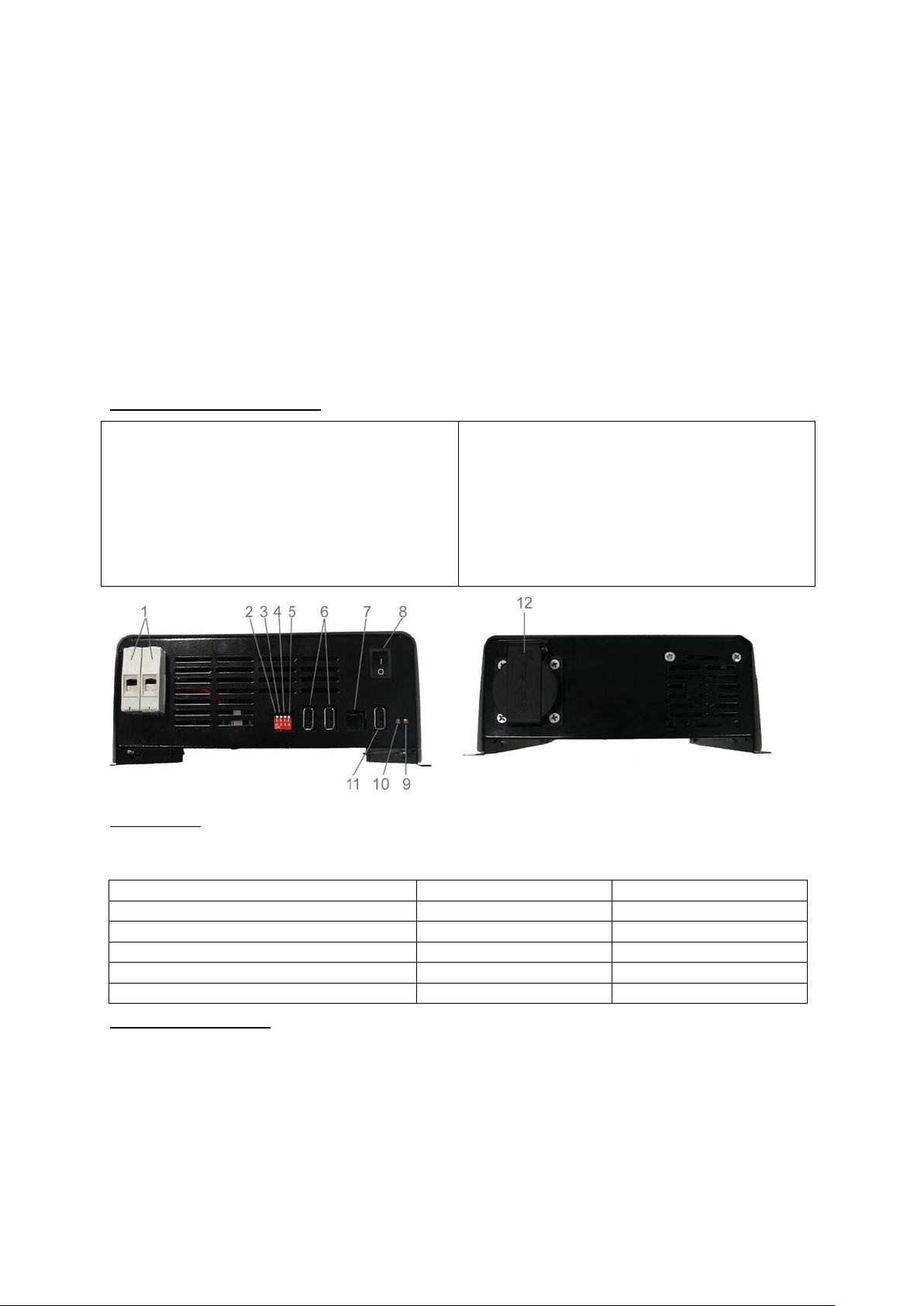
1. Connection terminals 12V/24V DC input
6. Connector f or remote cont rol FB-02 or FB-03
Operating status/ fault indicators
LED 9 (DC input)
LED 10 (AC output)
Device is switched on and ready for operation
LED is on (green)
LED is on (green)
Early warning for deep discharge protection
Slow blinking (green)
LED is on (green)
Cut-off due to deep discharge protection
Fast blinking (green)
Fast blinking (green)
Input overvoltage
Fast blinking (green)
Fast blinking (green)
Output short-circuit or overload
Fast blinking (green)
Fast blinking (green)
electronic starter or electronic ballast. Using conventional starters may lead to severe damage of the
voltage converter.
• AC outputs of several power sources may not be connected in parallel! Do not connect AC generators or
mains voltage to the AC output of the voltage converter. This leads to the immediate destruction of the
voltage converter!
• Never open the voltage converter! Even after disconnecting the device from the battery there may be
hazardous voltages in the interior of the device. This is why service and repairs may only be carried out by
authorized and qualified personnel.
Warning: Improper assembly may cause hazardous contact voltages even on the closed device!
Notes on the battery
• If used improperly, lead batteries are a high risk for humans, animals and the environment. Always
observe the safety instructions of the battery manufacturer!
• Lead batteries contain aggressive corrosive acids. Avoid eye and skin contact with liquids from the battery!
Never disassemble lead batteries! Wash the parts of the skin affected thoroughly with water and soap. If
acid enters the eye, immediately flood the eye with running, clear and cool water! Then seek medical help
immediately! If acid contacts your clothing, wash immediately with soap and water!
Operation and display elements
2. Switch without configuration
3. On/Off switch, standby function
4. Switch for addresses, assignment for remote control FB02 or FB-03
5. Switch for addresses, assignment for remote control FB02 or FB-03
7. Connector for remote control FB-01
8. On/Off switch
9. LED control indicator for DC input
10. LED control indicator for AC output
11. USB output
12. 230V AC output
LED indicators
The LED control indicators 9 (DC input) and 10 (AC output) provide important information on the operating status of your
converter. Both LEDs work independently from one another. I.e., a failure in the DC input area has direct impact on the function
of the AC output; or a failure in the output area affects the input function directly.
Description of functions
The voltage converters of the DSW series are modern, microprocessor-c ontrolled devices which were developed for mobile
power supply. The voltage converters of the DSW series convert lower DC input voltage into higher AC output voltage and thus
allow for the usage of conventional 230V AC consumers on the road.
These devices offer real sinus alternating voltage which allows for a trouble-free operation also of difficult consumers such as
PCs, TV systems and devices with transformers.
Of course, all devices of the DWS sinus voltage converter series are equipped with all necessary safety features which
correspond to a state-of-the-art product.
Page 3

Features:
Model No.
Cable length up to
2 m
Cable length up to
3 m
DSW-300
16 mm²
16 mm²
DSW-600
16 mm²
16 mm²
DSW-1200
25 mm²
35 mm²
DSW-2000
35 mm²
50 mm²
DSW-2000S
35 mm²
50 mm²
• Real 230V AC 50Hz sinus output voltage
• Galvanically isolated
• High efficiency
• Precise 50Hz frequency
• Standby function
• Output- and temperature-controlled fan
• Soft start function for consumers with high starting current
• Various remote controls as accessories available
• Overvoltage shutdown
• Adjustable, dynamic deep discharge protection
• Overload management
• Short-circuit shutdown
• Reverse polarity protection
• Temperature-activated protective circuit
Connection
For connecting the DC line, please use cable as short as possible with sufficient cross-section and ensure good contact, both to
the battery and to the voltage converter.
To thin or loose connectors may cause fire due to overheating!
• Switch 8 on the front of the device must be set to “Off”.
• A high-current fuse must be installed directly at the battery. If this fuse is missing, there is a risk of fire in case of
short-circuit of the two connection cables.
• Now connect both connection cables to the battery (positive pole = red; negative pole = black.)
Attention! The charge of the big capacitors may cause a spark inside the voltage converter when the fuse is connected. This is
perfectly harmless.
Recommended minimum cable cross-sections for connection cables
The recommended minimum cable cross-section for connection cables depends on the input voltage and the length of the used
cable.
Ininitial operation
In order to guarantee appropriate initial operation, please read these operating instructions including safety
information completely and carefully before use.
Check the voltage converter before every start on possible damages. In case of damages, don’t start operation but contact an
authorized expert or our service.
Always ensure appropriate ventilation of your voltage converter. Never cover the ventilation slots of the voltage converter. Never
use the device in the vicinity of highly flammable materials.
Set up the voltage converter in such a way that it may not fall over or down.
During assembly ensure that the voltage converter is mounted in such a way that it is not accessible for children. Danger of life!
Check the voltage requirements of the consumers to be connected. Connect only consumers whose voltage specifications and
output correspond with those of the voltage converter. Do not connect defect or damaged consumers.
Operation
To switch the voltage converter on and off activate the on/off switch 8. Now you may connect your 230V AC consumer. The
sequence of switching on/off and connecting the consumers is reversible.
Note: When you switch off the voltage converter using on/off switch 8 or the remote control FB-01, no own power is required.
When you use the remote control FB-02 or FB-03 for this purpose, however, you only switch off the 230 V AC output with it, but
not the voltage converter. This is why it continues to require own power. To save energy, we recommend using switch 8 or the
remote control FB-01 only for switching off.
General notes on using AC consumers on voltage converters
In principle, all AC consumers may be operated on a sinus voltage converter. Observe, however, that for doing so you are
always restricted by the availability of the battery capacity and the output requirements of the individual AC consumers. For a
better assessment of the battery reserve, we recommend to familiarize yourself with some relevant characteristics of AC
consumers.
One important factor is the own power. Most consumers require a significantly higher starting current than indicated on the type
plate of the device. E.g. bulbs require starting current which is up to 8 times higher for approx. 1sec; refrigerators and TV
systems require starting current which is up to 10 times higher for 3 sec resp. approx. 1sec. This is why it is necessary when
choosing the voltage converter to ensure that corresponding output capacity is available. Therefore, a voltage converter m ust
provide a continuous output of 500 W (50 W x 10) to operate a small refrigerator with a continuous output of 50 W.
Page 4

Standby function
To conserve the life of the connected battery, you can activate the standby function on your voltage converter. For this purpose
activate switch 3 on your device. Now the voltage converter is in standby mode. This reduces the own power consumption
significantly. Now the device checks whether load is connected in intervals of 20 seconds. When the voltage converter
recognizes a load above standby level (see technical specs) , it connec ts the 230 AC output and is thus in normal operation
again.
USB output
The USB output may be used to supply various 5 V consumers with voltage.
Note: This output is not suitable for data transmission.
Safety and protection mechanisms
Overvoltage shutdown
The voltage converter switches off as soon as the value of the input voltage exceeds the starting value.
Attention! The voltage converter restarts automatically as soon as the voltage drops to the starting value.
Deep discharge protection
The voltage converter switches off as soon as the input voltage drops below the set value. This is to protect your battery against
deep discharge. The remote controls FB-02 and FB-03 are used to make your own adjustment of the deep discharge prot ect i on
individually between 9 V-11.5 V on the 12V version or 18-23 V on the 24V version. This adjustment is not possible without the
remote control FB-02 and FB-03. Ex works adjustment of the deep discharge protecti on for t he 12 V versions is 10.5 V and 21 V
for the 24 V versions.
Attention! The voltage converter restarts automatically, if the restart threshol d is reached. This volt age converter series is
equipped with a dynamic deep discharge protection. I. e., at high output the deep discharge protection is automatically reduced
by up to maximum 1.0 V of the set value.
Note: The restart threshold is a permanently set value which cannot be changed. The value is 12.5 V for the 12 V
versions and 25 V for the 24 V versions.
Temperature-activated protective circuit
The voltage converter switches off when the temperature inside the device is too high.
Attention! The voltage converter restarts automatically when it has reached its normal operating temperature.
Overload management
The voltage converter switches off when the output or the starting current of the connected devices is too high. Then the voltage
converter tries to restart (soft start). Should the device does not restart after repetitive attempts the voltage converter is not
suitable for the connected consumer.
Attention! The device restarts automatically when the overload is disconnected from the voltage converter.
Short-circuit shutdow n:
The voltage converter switches off when the output is short-circuited.
Attention! The voltage converter restarts automatically when short-circuit is fixed.
Reverse polarity protection
The voltage converter is protected against reverse polarity. This means that your voltage converter continues to be functional
when you connect it with correct polarity
.
Operation with remote control
Optionally, all models of this voltage converter series may be operated with remote control. You may choose between three
various versions.
FB-01: This model is a cable version which is directly connected to the voltage converter. It is equipped with an on/off switch
and two control indicators for DC input and AC output.
FB-02: This model is also cable-connected to t he voltage converter and is additi onal l y equipped with an LC Display. The displ ay
serves for both monitoring import ant values and maki ng adj ustments, e. g. deep discharge protect i on. The rem ote control is also
equipped with a SD card slot. This allows for storing important values and easily transferring them to your PC.
FB-03: This model is a radio version. The receiver is connected to the voltage converter. The display offers the same functions
and adjustment features as the DSW FB-02 display.
Adress settings:
Address settings enable control and data readout for up to 4 converters with one LCD remote control. The converter is assigned
an address from 1 to 4 by changing the DIP switch position (see picture). This setting is only required if the Remote is used for
more than one DSW converter.
Page 5

Digital Sinus Inverter 12V/24V
Technical data DSW Synchron
DSW-2000S 12 V
DSW-2000S 24 V
Rated voltage DC
12 V
24 V
Input voltage range
11-15 V
22-30 V
Max. input current
248 A
124 A
Input rating in no-load operation
13 VA
13 VA
Continuous output rating
2000 VA
2000 VA
Peak output rating
4000 VA
4000 VA
Output voltage AC
230 V AC ± 2 %
230 V AC ± 2 %
Frequency
50 Hz ± 1 %
50 Hz ± 1 %
Remote control
yes
yes
Dimensions
391 x 334 x 88
391 x 334 x 88
DSW-2000S (synchronous)
Brief description of the synchronous version:
Two DSW-2000S inverters are connected in parallel via an additional connection socket and synchronised to achieve a
permanent output of 4000 W. Please use only the synchronous cable supplied by the manufacturer.
The inverter DSW-2000S can be operated by remote control.
The two inverters can also be operated individually with the respective continuous output of 2000 W.
All of the other features and operation elements correspond to the DSW-2000, and were described in detail at the start of these
operating instructions.
Fig. 1 Fig. 2
1. Connection socket for synchronous cable
2. Synchronous cable
Connection of the DSW-2000S
In order to ensure a correct start-up, make sure to read these operating instructions and the safety warnings thoroughly and
attentively, and to observe these accordingly.
• Connect the two DSW-2000S units with the aid of the synchronous cable, as shown in Figs. 1 and 2.
• Use the shortest possible cable with an adequate cross section for the DC line, and make sure there is a good contact
at the battery and at the inverter.
• The recommended minimum cable cross section of connections cables for the DSW-2000S is 35 mm² for cable
lengths of 2 metres and 50 mm² for a cable length of 3 metres. Please see also the section “Recommended
minimum cable cross sections for connection cables”.
• Attention! Cables which are too thin, or loose connections can lead to fire due to overheating!
• The switch 8 on the front of the device must be at the “Off” position.
• A high current fuse must be installed directly at the battery. If this fuse is missing, a short circuit of the two connection
cables can cause a fire.
• Now connect both cables to the battery (plus pole = red; minus pole = black).
• Attention! The charging of the large capacitors inside the inverters can cause a spark when the fuse is connected.
This is completely harmless.
Starting up
• Before starting up, always check the inverter for possible damage. If there is damage, do not start the device, but
contact an authorised expert or our service department.
• Always make sure that the inverter is adequately ventilated. Never cover the ventilation slots on the inverter. Do not
operate the device in the proximity of easily flammable materials.
• Set up the inverter in such a way that it cannot tilt or fall over.
• Mount the inverter in such a way that it is inaccessible to children. Risk of death!
• Check the voltage requirements of the consumers to be connected. Only connect consumers whose voltage and
current specifications match those of the inverter. Do not connect any defective or damaged consumers.
For further information on the operation and the individual functions of the device, please see the sections “Operation”
and “General Instructions for the operation of AC consumers with inverters“
Page 6

Technical specifications
DSW-300/12
DSW-300/24
DSW-600/12
DSW-600/24
INPUT
DC rated voltage
12V
24V
12V
24V
DC voltage range
11-15V
22-30V
11-15V
22-30V
Max. input current
31A
15.5A
62A
31A
Adjustable deep discharge
protection
9.0 – 11.5V
18.0-23.0V
9.0-11.5V
18.0-23.0V
Early warning
deep discharge protection
1.0V by shutdown
1.0V by shutdown
1.0V by shutdown
1.0V by shutdown
Deep discharge protection
factory setting
10.5V in neutral
9.5V with nominal load
21.0V in neutral
19.0V with nominal load
10.5V in neutral
9.5V with nominal load
21.0V in neutral
19.0V with nominal load
Restart voltage
12.5V
25V
12.5V
25V
Shutdown, overvoltage
16V
32V
16V
32V
Input power, neutral
4VA
4VA
5VA
5VA
Input power, standby
0.4VA
0.4VA
0.5VA
0.5VA
OUTPUT
Output voltage
230V AC +/-2%
230V AC +/-2%
230V AC +/-2%
230V AC +/-2%
Frequency
50Hz +/-1%
50Hz +/-1%
50Hz +/-1%
50Hz +/-1%
Permanent output current
1.3Aeff
1.3Aeff
2.6Aeff
2.6Aeff
Permanent output power (cos
φ > 0.8)
300VA
300VA
600VA
600VA
Peak output power (cos φ >
0.8) max. 2sec
600VA
600VA
1200VA
1200VA
Efficiency
typ. 90%
typ. 90%
typ. 90%
typ. 90%
Standby level
Output current < 0.1A
Output current < 0.1A
Output current < 0.2A
Output current < 0.2A
GENERAL
230VAC output
1x push socket
1x push socket
1x push socket
1x push socket
USB output, type A socket
5VDC 500mA
5VDC 500mA
5VDC 500mA
5VDC 500mA
range
-25 to +60°C at 66%
nominal output
-25 to +60°C at 66%
nominal output
-25 to +60°C at 66%
nominal output
-25 to +60°C at 66%
nominal output
Dimensions LxWxH
263x164x88mm
263x164x88mm
277x234x88mm
277x234x88mm
Weight
1.8kg
1.8kg
2.9kg
2.9kg
DSW-1200/12
DSW-1200/24
DSW-2000/12
DSW-2000/24
INPUT
DC rated voltage
12V
24V
12V
24V
DC voltage range
11-15V
22-30V
11-15V
22-30V
Max. input current
124A
62A
248A
124A
Adjustable deep discharge
protection
9.0-11.5V
18.0-23.0V
9.0-11.5V
18.0-23.0V
Early warning
deep discharge protection
1.0V by shutdown
1.0V by shutdown
1.0V by shutdown
1.0V by shutdown
Deep discharge protection
factory setting
10.5V in neutral
9.5V with nominal load
21.0V in neutral
19.0V with nominal load
10.5V in neutral
9.5V with nominal load
21.0V in neutral
19.0V with nominal load
Restart voltage
12.5V
25V
12.5V
25V
Shutdown, overvoltage
16V
32V
16V
32V
Input power, neutral
9VA
9VA
13VA
13VA
Input power, standby
0.9VA
0.9VA
1.3VA
1.3VA
OUTPUT
Output voltage
230V AC +/-2%
230V AC +/-2%
230V AC +/-2%
230V AC +/-2%
Frequency
50Hz +/-1%
50Hz +/-1%
50Hz +/-1%
50Hz +/-1%
Permanent output current
5.2Aeff
5.2Aeff
8.7Aeff
8.7Aeff
Permanent output power (cos
φ > 0.8)
1200VA
1200VA
2000VA
2000VA
Peak output power (cos φ >
0.8) max. 2sec
2400VA
2400VA
4000VA
4000VA
Efficiency
typ. 90%
typ. 90%
typ. 90%
typ. 90%
Standby level
Output current < 0.3A
Output current < 0.3A
Output current < 0.4A
Output current < 0.4A
GENERAL
230VAC output
1x push socket
1x push socket
1x push socket
1x push socket
USB output, type A socket
5VDC 500mA
5VDC 500mA
5VDC 500mA
5VDC 500mA
range
-25 to +60°C at 66%
nominal output
-25 to +60°C at 66%
nominal output
-25 to +60°C at 66%
nominal output
-25 to +60°C at 66%
nominal output
Dimensions LxWxH
391x234x88mm
391x234x88mm
391x334x88mm
391x334x88mm
Weight
3.5kg
3.5kg
4.8kg
4.8kg
Environmental protection note
administration office for the appropriate disposal center.
Permissible temperature
nominal output
-25 to +40°C at100%
nominal output
-25 to +40°C at100%
nominal output
-25 to +40°C at100%
nominal output
-25 to +40°C at100%
Permissible temperature
At the end of its useful life, this product must not be disposed of together with normal household waste, but has to be dropped off at a
collection centre for the recycling of electrical and electronic devices. This is indicated by the symbol on the product, on the
instruction manual or on the packaging.
The materials of which this product is made are recyclable pursuant to their labeling. With the reuse, the recycling of the materials or
other forms of scrap usage you are making an important contribution to the protection of the environment. Please ask your local
Technical specifications are subject to change. We assume no liability for typographical errors. V5_11/2013
Phone: 09622-719910, fax: 09622-7199120; Info@IVT-Hirschau.de; www.IVT-Hirschau.de
nominal output
-25 to +40°C at100%
nominal output
-25 to +40°C at100%
nominal output
-25 to +40°C at100%
IVT Innovative Versorgungs-Technik GmbH, Dienhof 14, D-92242 Hirschau
nominal output
-25 to +40°C at100%
 Loading...