

Page 1

TopPage
AYXP12FRN
SERVICE MANUAL
SPLIT TYPE
ROOM AIR CONDITIONER
MODELS
CONTENTS
CHAPTER 1. SPECIFICATION
[1] SPECIFICATION............................................ 1-1
[2] EXTERNAL DIMENSION............................... 1-2
[3] WIRING DIAGRM .......................................... 1-3
[4] ELECTRICAL PARTS .................................... 1-3
CHAPTER 2. EXPLAMATION OF CIRCUIT AND OPERATION
[1] BLOCK DIAGRAMS....................................... 2-1
[2] MICROCOMPUTER CONTROL SYSTEM........ 2-3
[3] FUNCTION..................................................... 2-8
CHAPTER 3. FUNCTION AND OPERATION OF PROTECTIVE PROCEDURES
[1] PROTECTION DEVICE FUNCTIONS AND
OPERATIONS................................................ 3-1
[2] AIR CONDITIONER OPERATION IN
THERMISTOR ERROR ................................. 3-3
INDOOR UNIT
AY-XP12FR-N
OUTDOOR UNIT
AE-X12FR-N
In the interests of user-safety (Required by safety regulations in some
countries) the set should be restored to its original condition and only
parts identical to those specified should be used.
[3] THERMISTOR TEMPERATURE CHAR-
ACTERISTICS...............................................3-5
[4] HOW TO OPERATE THE OUTDOOR
UNIT INDEPENDENTLY ...............................3-7
[5] GENERAL TROUBLESHOOTING CHART........3-7
[6] MALFUNCTION (PARTS) CHECK METH-
OD .................................................................3-9
[7] OUTDOOR UNIT CHECK METHOD........... 3-11
[8] TROUBLESHOOTING GUIDE ....................3-14
CHAPTER 4. REFRIGERATION CYCLE
[1] FLOW FOW REFRIGERANT ........................4-1
[2] STANDARD CONDITION ..............................4-1
[3] TEMPERATURE AT EACH PART AND
PRESSURE IN 3-WAY VALVE ......................4-1
[4] PERFORMANCE CURVES...........................4-2
Parts marked with " " are important for maintaining the safety of the set. Be sure to replace these parts with specified ones for maintaining the
safety and performance of the set.
This document has been published to be used for
after sales service only.
The contents are subject to change without notice.
Page 2

AYXP12FRN
AYXP12FRN
CHAPTER 1. SPECIFICATION
Service Manual
[1] SPECIFICATION
1. AY-XP12FR-N – AE-X12FR-N
MODEL INDOOR UNIT OUTDOOR UNIT
ITEMS AY-XP12FR-N AE-X12FR-N
Cooling capacity(Min. > Max.) kW 3.5 (0.9 - 4.0)
Heating capacity(Min. > Max.) kW 4.2 (0.9 - 6.0)
Moisture removal(at cooling) Liters/h 1.1
Electrical data
Phase Single
Rated frequency Hz 50
Rated voltage V 230
Rated current ✩
(Min - Max.)
Rated input ✩
(Min - Max.)
Power factor ✩ Cool % 91
Compressor Type Hermetically sealed rotary type
Refrigerant system Evaporator Louver Fin and Grooved tube type
Noise level
(at cooling)
Fan system
Drive Direct drive
Air flow quantity
(at cooling)
Fan Cross flow fan Propeller fan
Connections
Refrigerant coupling Flare type
Refrigerant tube size Gas, Liquid 1/2", 1/4"
Drain piping mm O.D φ18
Others
Safety device Compressor: Thermal protector
Air filters Polypropylene net (Washable)
Net dimensions Width mm 790 780
Net weight kg 10 37
NOTE: The condition of star”✩” marked item are ‘ISO5151’ : 1994(E), contition T1.
Cool A 4.3 (0.8 - 6.0)
Heat A 4.5 (0.7 - 7.5)
Cool W 900 (150 - 1300)
Heat W 970 (130 - 1700)
Heat % 94
Model 5RS092XDF
Oil charge 320cc (RB68A or Freil Alphc 68M)
Condenser Corrugate Fin and Grooved tube type
Control Expansion valve
Refrigerant (R410A) 1000g
De-lce system Micro computer controled reversed systems
High dB(A) 43 49
Low dB(A) 39 –
Soft dB(A) 27 –
High m3/min. 10.7 30.2
Low m3/min. 9.3 –
Soft m3/min. 6.0 –
Fan motors: Thermal fuse
Fuse, Micro computer control
Height mm 278 540
Depth mm 198 265
1 – 1
Page 3

[2] EXTERNAL DIMENSION
1. Indoor unit
AYXP12FRN
198790
278
2. Outdoor unit
58
INVERTERAIRCONDITIONER
540
780
175
12
37.5
58
18.5
22.0
135
4.5
72
299
14
324
265
540
1 – 2
165
81
136
Page 4

AYXP12FRN
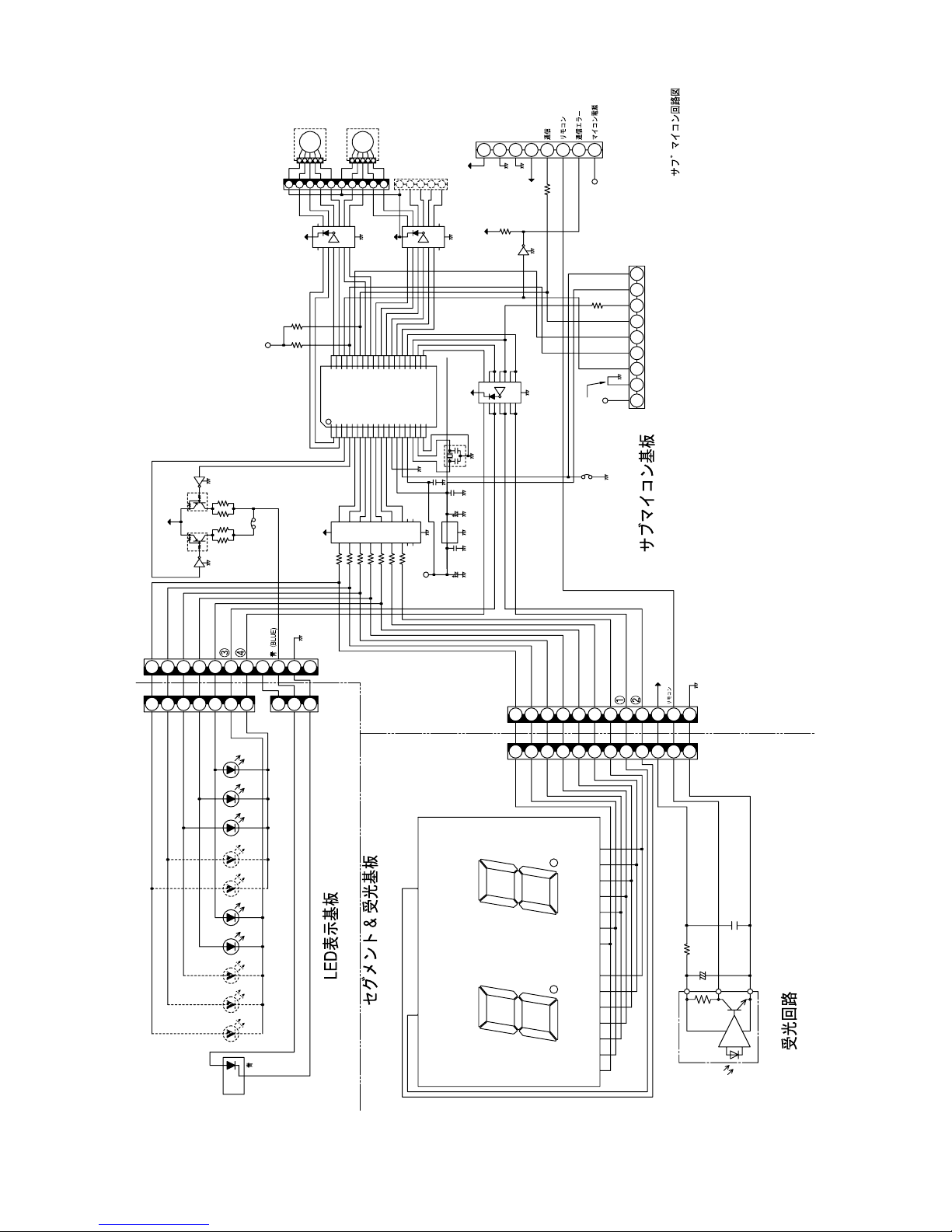
[3] WIRING DIAGRM
1. Indoor unit
2. Outdoor unit
[4] ELECTRICAL PARTS
1. Indoor unit
DESCRIPTION MODEL REMARKS
Indoor fan motor MLB084 DC Motor
Indoor fan motor capacitor – –
Transformer – –
FUSE1 – QFS-GA062JBZZ (250V, 3.15A)
FUSE2 – QFS-GA063JBZZ (250V, 2A)
2. Outdoor Unit
DESCRIPTION MODEL REMARKS
Compressor 5RS092XDF D.C. brush-less motor
Outdoor fan motor ML-A902 DC Motor
Outdoor fan motor capacitor – –
Fu4 – QFS-GA064JBZZ(250V, 1A)
Fu3 – QFS-GA051JBZZ(250V, 2A)
Fu2 – QFS-GA052JBZZ(250V, 3.15A)
Fu1 – QFS-CA001JBZZ(250V, 20A)
Fu5, 6 – QFS-CA002JBZZ(250V, 15A)
1 – 3
Page 5

AYXP12FRN
CHAPTER 2. EXPLAMATION OF CIRCUIT AND OPERATION
Service Manual
[1] BLOCK DIAGRAMS
1. Indoor unit
AYXP12FRN
CPU
DC power supply circuit
Fan motor PWM control circuit
Rotation pulse input circuit
AC clock circuit
Remote controller signal reception circuit
Buzzer drive circuit
CPU reset circuit
CPU oscillator circuit
Room temp. detect circuit
Heat exchanger pipe thermo circuit
EEPROM
Select circuit
Serial I/O circuit
Power supply relay drive circuit
2A
Rectification circuit
Fuse
Indoor fan motor
Fan motor pulse detect
Wireless remote control operation
Audible operation confirmation
Room temp. thermistor
Heat exchanger pipe thermistor
Louvre angle, fan speed
Wireless, preheat, Model select
Indoor/outdoor control signal I/O
Outdoor unit power supply on/off control
3.15A
AC power
Fuse
Unit-unit wiring
(AC power and
serial signals)
Serial signals
Sub
CPU
Auto restart circuit
Test run circuit
Auxiliary mode
Power on circuit
Cluster generator drive circuit
Louvre motor drive circuit(upper)
Louvre motor drive circuit(lower)
LED drive circuit
Test run (forced operation)
Auxiliary mode button ON/OFF
Self diagnostics, fault diagnosis
Cluster generator
Flow direction control (louver motor upper)
Flow direction control (louver motor lower)
LED display
2 – 1
Page 6

AYXP12FRN
2. Outdoor unit
CPU
AC clock circuit
Pulse amplitube modulation circuit
Power supply circuit
CPU oscillator circuit
DC overvoltage detection circuit
Outdoor fan drive circuit
4-way valve relay drive circuit
DC overcurrent detection circuit
Power transistor module drive circuit
Serial I/O circuit
CPU reset circuit
Position detection circuit
AC overcurrent detection circuit
Compressor thermo circuit
Heat exchanger pipe thermo circuit
Outdoor temp. thermo. circuit
Smoothing
circuit
15A
protection
IGBT
Power factor
converter circuit
Outdoor fan
4-way valve
Power transistor module
Compressor
Current transformer
Compressor thermistor
Heat exchanger pipe thermistor
Outdoor temperature thermistor
Filter
circuit
20A
protection
3.15A
protection
15A
protection
Unit-unit wiring (AC power
and serial signals)
EEPROM
LED drive circuit
Test mode circuit
Expansion valve drive circuit Expansion valve
Suction temp. thermo. circuit Suction pipe thermistor
2-way valve temp. thermo. circuit 2-way valve thermistor
LED
2 – 2
Page 7

[2] MICROCOMPUTER CONTROL SYSTEM
1. Indoor unit
1.1. Electronic control circuit diagram
AYXP12FRN
1
12V
CNA
BCN5
FU1
3.15A - 250V
RHRE
C23
275V
0.01μ
1W
R76
100
12V
E
D3
C53~C56
250V4700p
C54C53
C56
C55
R1
3.3
FU2
C35
5
1
D15
D1FL20U
10KF
R22 R3
11KF
ZD1
ST03D - 200
65432
TR1
R13
100K
12V
5V
1
1
1
D1N60
5W
1M
R2
2A - 250V
2KV
C12
9
C43
N
1
3W
3W
R75
C1
33p
D21
D1FL20U
R5
30KF
100V
100pF
D14
25V
R10
2
IN
RY1
3
365
3
11K
11K
SSR
3.3K
200K
R26
1/2W
DB1
D2SBA60
450V 120μ
1/2W1M1/2W
RF
D20
D1FL20U
2
C2
50V
100μ
C5
50V
ZD5
15V
101112
D2S6M
470μ
1.5K
2
1
3
OUT
CLUSTER
GENERATOR
5
6
(CLUSTER)
CONNECTOROF JOINT
910
R20
1/4W
R23
910
1/4W
39K
R24
R25
200K
1/2W
NR1
C14 275V 0.1μ
R19A 1/2W 470K
R19 1/2W 470K
NF1
C45 275V 0.1μ
DC15V
IC7
KIA7815API
Q9
D
KRA106S
1SR139
5V
L2
3
IC3
4
MR1712
R65
1500p
D2
D1FL20U
1
C49
C48
250V
10000p
C7
10V
D1
D1FS4
R6
L1
100K
10μH
1K
R9
C4
PC6
2
1
PC817XP3
R80
1.2K
2.4KFR82.4KF
N
N
S
CONNECTOROF JOINT
100μ
35V
C46
0.1μ
25V
C50
0.1μ
50V
C47
4
1
3.3K
R66
100K
R73
1234
CN80
R7
15KF
4
PC6
470μ
C44
10V
220μ
50V
0.1μ
R11
RA
RG R40RBRC
D8
7
(FANMOTOR)
77
BCN1
Vm
R31
56k
14
PC5
5V
32
PC9
PC817XP3
100μ
50V
C3
5V
3
5V
2W
680
2W
680
2W
680680
2W
2W
680
D1N60
D1N60
D7
DC
5
521
5
10K
R16
R34
6.8k
R57
680
0V
C40
50V
1000p
4
PC7
PC817XP3
1
1K
R81
IC9
PJ431CT
41
FAN
MOTOR
33
312
23
14
23
4.7k
R39
PC1 PC817XP3
C20 250V0.01μ
R38 100k
C19 50V0.047μ
C18 35V100μ
ZD2HZ24-2
2W
2W
11K
11K
R37RD
2.7K
R70
R44
12V
5V
C42
1
2
4
PC3
1
Vs
VccPGGND
C98
C99
6.8k
R33
16V47μ
C21
R32
3
PC817XP3
2
14
3.3k
R29
JPF
32
PC817XP3
R41 56k
32
PC2 PC853HXP
(SERIAL I/O CIRCUIT)
89
BZ
1.8k
1/4W
12V
25V
0.1μ
3
PC81716P
2
C16
50V
0.01μ
C98, C99
1KV 1000p
8.2k
PC4
PC817XP3
R35 10k
680
R30
R27
10K
AC CLOCK
5V
5V
JPS
IC6
16V
C17
10k
R28
R71
4.7K
R36
16V
C22
0.01μ
1k
4.7k
R47
4.7k
R97
KID65004AF
0.01μ
1110
987654321
10
SUB MICRO COMPUTER PWB
7654321
9876
12345
8
123456789
1210 11
1110 12 10 11
987654321
123456789
RECEIVER PWB
7-SEGLED&
BOTTOM
33
LOUVER MOTOR
CIRCUIT DIAGRAM
54 21 54 21
TOP
LOUVER MOTOR
DISPLAY PWB
246
8
10
13579
8765432
POWERSUPPLY OF
SUBMICRO COMPUTER
KRC108S
4.7K
R98
16V
0.01μ
10K
R61
C31
1
CN4
BCN7
10.0KF
16V10μ
RM
49P37
50
51
52
53
54
55
56
57
58
59
60
61
62
63
64
JPH
5V
11 12
4.7K
484746454443424140393837363534
P00
P01
P02
P03
P04
P05
P06
P36
P35
P34
P33
P32
P31
P30
VCC
VR
VSS
P67
P66
P65
P64
P63
HOT KEEP
P07
P53
P54
P55
P56
P57
P60
P61
P62
123
4
R52
10K
R53
10K
JPO
(HA CIRCUIT)
AUTO RESTART
5V
FLASH
P10
P52
98765
HAJP
POWERON
BUSY
P11
IC1
P51
10
R95
P12
P13
P47
P50
R91
4.7K
VPP
DRAIN PAN ASS'Y
P14
P15
P16
P44
P45
P46
1514131211
100k
R93
C90
R90
4
321
100K
R69
4.7K
R68
VCC
SCL
P20
P17 33
P21
P22
P23
P24
P25
P26
P27
VSS
XOU
XIN
P40
P41
RST
VSS
P42
P43
16
R92
CN90
SDAOERESET9VSS
4.7k
R45
32
31
30
29
28
27
26
25
24
23
22
21
20
19
18
17
MQ
7654321
8
5V
10k
R48
10K
R94
C27
16V
0.01μ
13
50V
C33
8MHz
AUX.
5V
(TESTRUN)
R87
WIRELESS
1000p
2
47k
R67
SW1
10k
R50
TEST
C37
25V
0.1μ
C26
25V
4.7μ
IC2
RESET
10K
C52
25V
0.1μ
C
50V
0.1μ
OSC1
R85
10K
C57
50V
1000p
R86
10K
JPW
JPP
5V
PREHEAT
(DRAINPAN)
CONNECTOROF JOINT
8
6
43
21
7
5
1
12V
Q11
5V
4.7K
R4
5V
50V
C32
1000p
R17 1K
100μ
10V
C25
5V
0.1μ
25V
C24
1k
R46
4
5
3
6
2
7
1
8
IC10
EEPROM
5V
10.0KF
R96
100
1/4W
R56
100
5V
1/4W
R51
JPT
GND for
KRA101S
1K
R89
R54
10K
12V LINE
Q15
Q19
2.4K
R55
GND for
5V LINE
KRC102S
KRC108S
KRC102S
4.7K
RN
4
TEMP THERMO
SIGNAL
5V
OFSERIAL
SERIALSIGNALS
REMOTECONTROLLER
ERRORSIGNAL
Q3
Q1
5V
C39
C36
16V
0.01μ
R58
R59
10K
10.0KF
R60
16V10μ
C30
3
2
TH1
TH2
PIPE THERMO
2 – 3
Page 8
AYXP12FRN
1.2. Display circuit diagram
IC105
TOP
5432112345
LOUVER MOTOR
12V
12V LINE
GND for
KID65004AF
IC106
1234567
CN101
12V
12345
CN102
GND for
12V LINE
8
SIGNALS
4.7K
KRC106S
SERIAL SIGNALS
ERROR SIGNAL
REMOTE CONTROLLER
OF SERIAL
M5V
POWER SUPPLY OF
SUB MICRO COMPUTER
9
5V
R108
5V LINE
GND for
12V LINE
GND for
1K5VR119
Q105
CIRCUIT DAIGRAM
LOUVER MOTOR
987654321
10
CN103
12V
KID65004AF
BOTTOM
8
7
4.7K
R115
R116
100K
6
5
M5V
R118
10K
IC101
Q104
KRC106S
R114
KRA106S
Q102Q101
12V
KRA106S
Q103
KRC106S
R110
R113
R109
JP2
1/4W
1.2K*4
KID65783AF
12V
1W180*7
P11 36
M37542
P12
123
R101
P01 28
P02 29
P03 30
P04 31
P05 32
P06 33
P07 34
P10 35
P13
P14
P20
P21
P22
P23
P24
P25
4
98765
IC103
R102
R103
R104
R105
P30 19
P31 20
P32 21
P33 22
P34 23
P35 24
P36 25
P37 26
P00 27
12V
IC104
GND for
KID65004AF
Vss18
Xout17
P26
P27
Vref
RESET
CNVss
Vcc
Xin
16
1514131211
10
R106
R107
13
8MHz
2
OSC101
25V
C101
0.1μ
50V
C105
0.22μ
C102
25V
4.7μ
IC102
RESET
25V
C103
C104
0.1μ
16V
47μ
12V LINE
GND for
M5V
12V LINE
5V LINE
GND for
JP1
4
3
2
1
M5V
FLASH
SUB MICRO COMPUTER PWB
cdefg
123456789
7
6
5
4
3
2
1
LED LED LED LED LED LED LED LED
LEDLED
101 102 103 104 105 106 107 108 109 110
LED
PC
111B
CN105B
BLU
()
10
123
E
12V LINE
GND for
11
CN105A
CN105C
abcdefg
6
5
4
3
2
1
8
7
123456789
SIGNALS
5V LINE
GND for
5V
REMOTE CONTROLLER
9
12
11
1010
11
12
CN104B CN104A
2 (H2)
9(G2)
g
8(F2)
f
3 (E2)
e
1 (D2)
d
4 (C2)
c
6 (B2)
b
7 (A2)
a
2 (H1)
9(G1)
g
8(F1)
f
3 (E1)
e
1 (D1)
d
4 (C1)
c
6 (B1)
b
7 (A1)
a
R201
47
C201
+
16V
47μ
C202
25V
0.1μ
IC201
GP1U261RK
RECEIVER CIRCUIT
DISPLAY PWB
7 - SEG LED & RECEIVER PWB
SG201
B2B1
A2
(COM) 5
F2
A1
(COM) 10
F1
H2
C2
G2G1
D2
E2
H1
C1
D1
E1
2 – 4
Page 9

1.3. Printed wiring board
AYXP12FRN
2 – 5
Page 10

AYXP12FRN
2. Outdoor unit
2.1. Electronic control circuit diagram
PS21563 or 21564
IPM
15A
FU5
250V
j
PTC
1μF
275V
275V
1μF
275V
FC1
TERMINAL
BOARD
WP
VP
UP
VPI
EARTH
YELLOW
GREEN/
C
(R)
S
(THERMISTOR)
5V
(C)
R100
R
FC3 FC4
(THERMISTOR CIRCUIT)
T9
T7
T8
V33
U32
W34
N
35
R50
26
CIN
R128
R7
MRY1
2.7kF
R88
13KF
R127
R6
23.7KF
510K
4
2
4
2
T1
0V
1/4W
BROWN
1
13KF
23.7KF
T11
T10
T13
25
CF0
Q7
5V
R107
2
0V
8
6
150
R110
-P
V
Q5
18
FU6
15A
250V
WH
WH
e
d
D12
D13
FU2
3.15A
250V
4700pF
250V
C6A
C6
C7A
C7
4700pF
250V
4700pF
250V
C5A
C5
C4
C4A
4700pF
250V
PC1
SA1
NR1
C13
20A
FU1
250V
T4
YELLOW
GREEN/
31
P
M
C14
630V
0.33μ
R126
1/2W
R125
1/2W
270KD
270KD
R5
R2
1/2W
300KF
255KF
1/2W
C10
750μ
+
C9
420V 420V
750μ
+
DB1
T5
GR
GR
OUT
IN
GR
T6
CT1
R89
C3
1/4W
510K
R43
3
L4
1
C2
3
L3
1
1μF
C1
R1
1M
T12
1/2W
T2
BLUE
N
1
330K
10K x 5 R63 ~ 67
5W
R49
0.02
1.8KF
C59
C58
c
KRC105S
330
PC4
3
R101, 102
1/2W 47K x 2
5V
4
1
PC817XP3
0.1μ
D1
FC2
R51 ~ 53
R111
ZD3
1000P
0.022μ
TLP351
5
2.2K
R103, 104
R74
TH4
TH5
TH3
TH2
65432
798
10
CN8
R68 ~ 72
6.8KF x 5
D11
0V
C70 ~ 74
16V 10μ x 5
0V
0.01μ x 5 C65 ~ 69
1/2W
470KF x 3
R99 100
15K
R112
R57 100
R59 100
R58 100
0V
D24
D23
D22
V
D21
5
11
4
15
3
2
14
13
R114
1M
1.8K
0V - P
R115
5V
1.8K
R60
1.8K
R61
1.8K
DB2
R62
μ
7
9
.01
C
0
6
K
5V
.3
C83
3
R10
220μ
1000P
1
4
1000P
6
Q
0V
2S
μ
2
0V
0V
R41 R42
01
C8
KRC10
0.
5
2K
0
2
1
R
5V5V
3
4
PC3
2
1
PC81716NIP
C81
0.01μ
R146
100K
5
2
R
b
R75
2.7K
R76
56K
D6
2
TR1
3
(SERIAL I/O CIRCUIT)
1K
2W
1K
1K
2W 2W
FB
R11
1/2W 1M
V
0
5
2
U4
F
A
1
j
R8R9R10
1/2W 1M
R147
10K
C79
10V
R91
6.8KF
R90
1.0KF
D2
R104
R103
R102
R101
1W 47K x 2
a
C75
4.7K
3
PC2
PC853HXP
2
R4
3.3K
250V
C12
4700P
T3
RED
2
VUFS
VUFB
IPM
3
4
1
C49
0.1μ
33 x 2
33 x 2
D8
C50
R47A, 48A
25V
R47, 48
1/4W
1/4W
100μ
C37
25V
ZD4
330μ
C38
0.1μ
15V
0V
R56
20.5KF
R55
20.5KF
R54
20.5KF
25V
C60
0.1μ
C86
0.1μ
R113
19.1KF
C61
330P
50V
DETECT CIRCUIT)
(ROTOR POSITION
50V
C62
330P
C63
50V
330P
C64
25V
0.1μ
678910
12
1
IC8
KIA339
5V
N
W
C93
0.1μ
V
C30
10V
U
5V
V
5V
15
13V
5
0
C4
I
8
7
7
W
8
1
6
R2
4
K
2
2
R
2
μ
3
1
KF
C2
.03
.65
0
1
3
K
IC3
2
8
R
6
1
2
.5K
R
1
2
K
0
R2
1
μ
0
V
0
2
5
8
C
2
6
9
V
μ
5
0
C1
3
5
1
7
D
8
7
3
1
7
0
W
1
D3
2
R1
D5
5
μ
V
0
0
C1
1
5
K
8
5
1
.
1
R
PF
7
0
KV
2
C2
1
2
rain
1~4
R12
1/2W 1M
1/2W 1M
D
R13
1/2W 1M
cc
8
V
C2
2
I
7
STR -L4
1/2W 1M
6
D20
100μ
3
C2
6
R2
2
K
0
R8
1
9
R1
G
6
8
5
SA1
2
VVFB
9
D9
C39
1000P
M
0V
a
b
R92
10K
μ
1
.
0
KF
4
.6
4
9
K
2
1
Q
ZD1
ce
r
6
ou
S
B
9
/F
P
OC
10
D
N
7
G
VVFS
10
7
C51
0.1μ
C52
25V
100μ
C40
1000P
1234567
CONNECTOR)
(FRASH WRITER
JP7
JP8
JP9
0V
S
T
Q
0V
-P
0V - P
V
18
μ
5
8
.1
C
0
7
K
0
R8
1
μ
V
0
5
5
C84
3
1
4
1
D
5
6
D4
P
0
5
6
0
3
3
D1
C1
K
0
3
.
R2
3
4
1
R
VPI
12
CND
1
2
34
5
6
7
89
10111213141516171819
11
0
8
6
VWFB
VWFS
15
13
C53
D10
25V
C54
100μ
C41
1000P
9
8
S
T
R
1
JP10
R154
10K
5V
(FOR DEBUG)
10K
R155
P42
P43
P44
P45
P46
P50
P51
P52
P53
P54
P55
P56
P57
AVCC
AVR
AVSS
P60
P61
P62
P63
MD0
RST
MD1
10K
10K
R94
R93
0V
5V
10
P
8
0
8
C1
6
6
.6
1
R1
5
.6
R1
1
P
7
0
7
C1
4
0V
VPI
18
16
0.1μ
C42
1000P
5V
Q
2
3
P40
P41
MD2X1X0
OSC1 4MHz
K
.7
R29
4
(SWITCHING POWER
(RESET CIRCUIT)
VNI
28
LED1
R73
2.2K
4
MONITOR
P37
VSS
0V
5V
13V
SUPPLY CIRCUIT)
IC5
5V
UN
22
21
C55
0.1μ
C56
0.1μ
C57
0.1μ
C44
C43
1000P
R134 100
R135 100
R136 100
R137 100
(LED CIRCUIT)
(CN)
5V
P33
P34
P35
VCCCP36
(Y)
(W)
(Z)
IC1
(B)
(O)
(Y)
P00
P01
P02
P03
P04
10K
10K
R35
R34
JP16
9
MRY1
RY1
13V
6
5
VALV COIL
EXPANSION
+
C33
R79
0.1μ
C32
100
3
2
1
PST993D
270
R78
C31
0.1μ
C
VN
1000P
P32
(V)
(W)
P05
4
50V
1μ
0V
VNO
F0
WN
23
N
VNC
24
27
20
35
JP17
0V
C47
10V
100μ
C48
0.1μ
10K
R45
5V
C45
0.1μ
1K
R46
0V
1000P
C46
(DC OVERCURRENT CHECK CIRCUIT)
R133 100
R132 100
0.1μ
C95
C94
100μ
10V
0.1μ
C98
V
W
JPF
KID65004AP
U
R38 1K
R37 1K
R36 1K
0V
C36
C35
C34
1000P x 3
c
0V
1K
10K
R129
4.7K
R30
5V
(PAM OVER CURRENT CIRCUIT)
RY1
e
CNE
IC6
10K
R31
R32
431
VALV
4-WAY
3
R28
1/2W
275V
C26
3
120
0.033μ
COIL
1
d
R144
2.2K
R33
2
8
756
0V
124
(EEPROM CIRCUIT)
CN4
NR2
(4 - WAY VALVECIRCUIT)
C76
1000P
0V
6.8K
JP2
0V
JP1
5V
C88
1000P
0V
1K
R116
N
52535455565758596061626364
(U)
P30
51504948474645444342414039383736353433
(X)
VSS
P27
(W)
(V)
P26
P25
(U)
P24
P23
P22
P21
P20
P17
P16
P15
P14
P13
P12
P11
P10
P07
P06 P31
32313029282726252423222120
8
IC7
0V
3
2
1
CN12
5V
Q9
R81
KRC105S
Q4
KRA106S
10K
KRC105S
0V
Q10
KRA106S
R84
9.53KF
10V
47μ
C78
0V
R86
6.8KJ
(FAN MOTOR CIRCUIT)
Q3
0V
C77
15V
0.01μ
6.8K
R85
5V
R83
10K
0V
C29
400V
0.1μ
1
7
3
2
4
CN3
5
R
270
R77
j
2A
FU3
250V
(FAN MOTOR)
2 – 6
Page 11

2.2. Printed wiring board
AYXP12FRN
2 – 7
Page 12

AYXP12FRN
[3] FUNCTION
1. Function
1.1. Startup control
The main relay remains off during the first 45 seconds (first safety
time) immediately after the power cord is plugged into an AC outlet in
order to disable outdoor unit operation and protect outdoor unit electric
components.
1.2. Restart control
Once the compressor stops operating, it will not restart for 180 seconds to protect the compressor.
Therefore, if the operating compressor is shut down from the remote
control and then turned back on immediately after, the compressor will
restart after a preset delay time.
(The indoor unit will restart operation immediately after the ON switch
is operated on the remote control.)
Compressor operation
Compressor ON Compressor can
Compressor remains OFF
turn ON
for 180 seconds
OFF operation on
remote control
ON operation on
remote control
Compressor ON
1.3. Cold air prevention control
When the air conditioner starts up in heating mode, the indoor unit fan
will not operate until the temperature of the indoor unit heat exchanger
reaches about 23°C in order to prevent cold air from blowing into the
room.
Also, the indoor unit fan operates at low speed until the temperature of
the indoor unit heat exchanger reaches about 38°C so that people in
the room will not feel chilly air flow.
Indoor unit heat exchanger temperature
38
23
Set fan speed
35
Indoor unit fan at low speed
21
Indoor unit fan in non-operation
1.6. Outdoor unit 2-way valve freeze prevention control
If the temperature of the outdoor unit 2-way valve remains below 0°C
for 10 consecutive minutes during cooling or dehumidifying operation,
the compressor operation stops temporarily in order to prevent freezing.
When the temperature of the 2-way valve rises to 10°C or higher after
about 180 seconds, the compressor restarts and resumes normal
operation.
1.7. Indoor unit overheat prevention control
During heating operation, if the temperature of the indoor unit heat
exchanger exceeds the indoor unit heat exchanger overheat prevention temperature (about 45 to 54°C) which is determined by the operating frequency and operating status, the operating frequency is
decreased by about 4 to 15 Hz. Then, this operation is repeated every
60 seconds until the temperature of the indoor unit heat exchanger
drops below the overheat protection temperature.
Once the temperature of the indoor unit heat exchanger drops below
the overheat protection temperature, the operating frequency is
increased by about 4 to 10 Hz every 60 seconds until the normal operation condition resumes.
If the temperature of the indoor unit heat exchanger exceeds the overheat protection temperature for 60 seconds at minimum operating frequency, the compressor stops operating and then restarts after about
180 seconds, and the abovementioned control is repeated.
1.8. Outdoor unit overheat prevention control
During cooling operation, if the temperature of the outdoor unit heat
exchanger exceeds the outdoor unit heat exchanger overheat prevention temperature (about 55°C), the operating frequency is decreased
by about 4 to 15 Hz. Then, this operation is repeated every 60 seconds until the temperature of the outdoor unit heat exchanger drops to
about 54°C or lower.
Once the temperature of the outdoor unit heat exchanger drops to
about 54°C or lower, the operating frequency is increased by about 4
to 10 Hz every 60 seconds until the normal operation condition
resumes.
If the temperature of the outdoor unit heat exchanger exceeds the outdoor unit heat exchanger overheat protection temperature for (120 sec
: outdoor temperature ≥ 40°C • 60 sec : outdoor temperature < 40°C)
at minimum operating frequency, the compressor stops operating and
then restarts after about 180 seconds, and the abovementioned control is repeated.
1.4. Odor prevention control
When the air conditioner starts up in cooling mode, the discharged air
temperature is lowered slightly, and for the reduction of unpleasant
odors the operation of the indoor unit fan is delayed 60 seconds if the
automatic fan speed mode in cooling mode is set.
1.5. Indoor unit heat exchanger freeze prevention control
If the temperature of the indoor unit heat exchanger remains below
0°C for 4 consecutive minutes during cooling or dehumidifying operation, the compressor operation stops temporarily in order to prevent
freezing.
When the temperature of the indoor unit heat exchanger rises to 2°C
or higher after about 180 seconds, the compressor restarts and
resumes normal operation.
1.9. Compressor overheat prevention control
If the temperature of the compressor exceeds the compressor overheat prevention temperature (110°C), the operation frequency is
decreased by about 4 to 10 Hz. Then, this operation is repeated every
60 seconds until the temperature of the compressor drops below the
overheat protection temperature (100°C).
Once the temperature of the compressor drops below the overheat
protection temperature, the operating frequency is increased by about
4 to 10 Hz every 60 seconds until the normal operation condition
resumes.
If the temperature of the compressor exceeds the overheat protection
temperature (for 120 seconds in cooling operation or 60 seconds in
heating operation) at minimum operating frequency, the compressor
stops operating and then restarts after about 180 seconds, and the
abovementioned control is repeated.
2 – 8
Page 13

1.10. Startup control
Heating operation
Set temperature
Activation of
OFF timer
1hour
later
Max.
1.5 hours
later
Max.
2 hours
later
Timer setting
reached
1hour
later
Max.
1.5 hours
later
Max.
2 hours
later
Timer setting
reached
Activation of
OFF timer
Set temperature
-1
O
C
-1
O
C
-1
O
C
0.3
O
C
0.3
O
C
0.3
O
C
Cooling/dehumidifying operation
When the air conditioner starts in the cooling or heating mode, if the
room temperature is 2°C higher than the set temperature (in cooling
operation) or 3.5°C lower (in heating operation), the air conditioner
operates with the operating frequency at maximum. Then, when the
set temperature is reached, the air conditioner operates at the operating frequency determined by fuzzy logic calculation, then enters the
normal control mode after a while.
1.11. Peak control
If the current flowing in the air conditioner exceeds the peak control
current (see the table below), the operation frequency is decreased
until the current value drops below the peak control current regardless
of the frequency control demand issued from the indoor unit based on
the room temperature.
AY-XP12FR-N Approx. 6.4 A Approx. 7.5 A
1.12. Outdoor unit fan delay control
The compressor stops immediately after cooling, dehumidifying or
heating operation is shut down, but the outdoor unit fan continues
operation for 50 seconds before it stops.
1.13. Defrosting
1.13.1 Reverse defrosting
The defrost operation starts when the compressor operating time
exceeds 20 minutes during heating operation, as shown below, and
the outside air temperature and the outdoor unit heat exchanger temperature meet certain conditions. When the defrost operation starts,
the indoor unit fan stops. The defrost operation stops when the outdoor unit heat exchanger temperature rises to about 13C or higher or
the defrosting time exceeds 10 minutes.
Start of
heating
operation
1.14. ON timer
The ON timer can be activated by pressing the ON timer button. When
the ON timer is activated, the operation start time is adjusted based on
fuzzy logic calculations 1 hour before the set time so that the room
temperature reaches the set temperature at the set time.
1.15. OFF timer
The OFF timer can be activated by pressing the OFF timer button.
When the OFF timer is set, the operation stops after the set time.
When this timer is set, the compressor operating frequency lowers for
quieter operation, and the room temperature is gradually varied after
one hour (reduced 1°C three times (max. 3°C) in heating, or increased
0.3°C three times (max. 1°C) in cooling or dehumidifying operation) so
that the room temperature remains suitable for comfortable sleeping.
Model Peak control current
Cooling operation Heating operation
20 min or more 20 min or more 20 min or more
Defrosting
Max. 10 min
Defrosting
Max. 10 min
AYXP12FRN
1.16. Power ON start
If a jumper cable is inserted in the location marked with HAJP on the
indoor unit control printed circuit board (control PCB), connecting the
power cord to an AC outlet starts the air conditioner in either cooling or
heating mode, which is determined automatically by the room temperature sensor.
When a circuit breaker is used to control the ON/OFF operation,
please insert a jumper as described above.
1.17. Self-diagnostic malfunction code display
1.17.1 Indoor unit
1) When a malfunction is confirmed, all relays turn off and a flashing
malfunction code number is displayed to indicate the type of malfunction.
When the air conditioner is in non-operating condition, holding
down AUX button for more than 5 seconds activates the malfunction code display function.
The operation continues only in the case of a serial open-circuit,
and the main relay turns off after 30 seconds if the open-circuit condition remains.
In the case of a serial short-circuit, the air conditioner continues
operating without a malfunction code display, and the main relay
turns off after 30 seconds if the short-circuit condition remains.
The malfunction information is stored in memory, and can be
recalled later and shown on display.
2) The self-diagnostic memory can be recalled and shown on the display by stopping the operation and holding down AUX button for
more than 5 seconds.
3) The content of self-diagnosis (malfunction mode) is indicated by a
flashing number.
(For details, refer to the troubleshooting section.)
1.17.2 Outdoor unit
If a malfunction occurs, LED1 on the outdoor unit flashes in 0.2-second intervals as shown below.
(Example) Compressor high temperature abnormality
ON
OFF
1 sec 1 sec 0.6 sec
2 – 9
Page 14

AYXP12FRN
1.18. Information about auto mode
In the AUTO mode, the temperature setting and mode are automatically selected according to the room temperature and outdoor temperature when the unit is turned on.
1.19. Airflow control
The airflow control holds the two upper and lower louvers at special
positions during operation to prevent discharged air from directly blowing onto people in the room.
Modes and Temperature Settings
1.19.1 Cooling/dehumidifying operation
When the airflow button is pressed the upper louver is set at an
upward angle to send the air along the ceiling.
1.19.2 Heating
When the airflow button is pressed the lower louver is set at a down-
the figures in ( ) are temperature settings
During operation, if the outdoor temperature changes, the temperature
settings will automatically slide as shown in the chart.
ward angle to send the air directly toward the floor.
1.20. Difference of operation in Auto and Manual modes
In the Auto mode, the temperature setting is automatically determined based on the outside air temperature. In addition, the air conditioner operation
differs from the operation in the Manual mode as explained below.
1.20.1 Difference relating to set temperature
Auto mode Manual mode
Cooling Heating Dehumidifying Cooling Heating Dehumidifying
Temperature
setting
method
Automatic temperature setting based on outside air temperature. Can be changed within ±2°C using remote control.
1.21. Dehumidifying operation control
If the room temperature is 26°C or higher when dehumidifying operation starts, the dehumidifying operation provides a low cooling effect in
accordance with the room temperature setting automatically determined based on the outside air operation. (The setting value is the
same as the set temperature for cooling operation in the auto mode.)
If the room temperature is lower than 26°C when dehumidifying operation starts, the dehumidifying operation minimizes the lowering of the
room temperature.
1.22. Self Clean operation
Heating or Fan operation and Cluster operation are performed simultaneously.
The judgment of whether Heating or Fan operation is used is based on
the outside air temperature at 3 minutes after the start of internal
cleaning.
The operation stops after 40 minutes. (The air conditioner shows the
remaining minutes: 40 → 39 → 38 ... 3 → 2 → 1)
Heating operation Fan operation
Outside air temperature
24OC
1.23. Plasmacluster Ion function
Operating the Plasmacluster Ion button while the air conditioner is in
operation or in non-operation allows the switching of the operation
mode in the following sequence: “Air Clean operation” → “Stop”.
• “Self Clean operation” generates about equal amounts of (+)ions
and (-)ions from the cluster unit to provide clean air.
If the Plasmacluster Ion generation function is operated together with
the air conditioner operation, the indoor unit fan speed and louver
direction are in accordance with the air conditioner settings.
If the Plasmacluster Ion generation function is used without operating
the air conditioning function, the indoor unit fan operates at a very low
speed and the upper louver is angled upward and the lower louver
remains horizontal. (The airflow volume and direction can be changed
by using the remote control.)
Can be changed
between 18 and 32°C
using remote control.
Can be changed
between 18 and 32°C
using remote control.
1.24. Hot keep
When the room temperature rises above the set temperature by 0.6°C
or more, the ON/OFF operation of the compressor and indoor unit fan
is controlled in order to lower the room temperature.
(The values indicated below, such as "0.6°C" and "1.3°C," vary
depending on the outside air temperature.)
1.3OC
O
0.6
C
Set temperature
1.24.1 Hot keep zone 1
With the compressor frequency at the lowest, if the room temperature
is higher than the set temperature by 0.6°C but no more than 1.3°C,
the following processes will be activated.
1) The compressor stops temporarily, and restarts after 2 minutes.
2) If the room temperature remains in the hot keep zone, the compressor is turned OFF and ON in 3-minute intervals.
3) The indoor unit fan turns OFF and ON with a delay of 30 seconds
from the compressor OFF/ON.
4) After the above operation in 3-minute intervals is repeated four
times, the interval extends to 6 minutes.
1.24.2 Hot keep zone 2
If the compressor ON/OFF in hot keep zone 1 fails to bring the room
temperature within 1.3°C above the set temperature, the following processes will be activated.
1) The compressor repeats a cycle of 8-minute OFF and 6-minute
ON.
2) After the second time, the compressor remains completely OFF
and only the indoor unit fan repeats OFF-ON in set intervals.
3) While the compressor is completely OFF in 2), the louvers are set
horizontally to prevent cold air from blowing.
The zone transition and the end of hot keep operation (room temperature lower than the set temperature) are judged when the compressor
ON period ends.
* This function cannot be repealed.
Automatic setting.
Can be changed
within ±2°C.
2 – 10
Page 15

AYXP12FRN
1.25. Winter cool
Cooling operation is available during the winter season by the built in
winter cool function.
Lower limit of outdoor temperature range is -10°C DB.
When the outside air temperature is low, the outdoor unit fan operates
at slower speed.
NOTE: Built-in protect device may work when outdoor temperature
falls below 21°C DB., depending on conditions.
1.26. Auto restart
When power failure occures, after power is recovered, the unit will
automatically restart in the same setting which were active before the
power failure.
1.26.1 Operating mode (Cool, Heat, Dry)
• Temperature adjustment (within 2°C range) automatic operation
• Temperature setting
2. Explanation of cluster circuit
The cluster unit generates cluster ions, which are circulated throughout the room by the air flow created by the blower fan (indoor unit fan motor) in
the air conditioner unit.
1) When microcomputer output turns "H," the IC6 output changes to "Lo," turning ON the SSR and applying 230 V to the cluster unit for the generation of cluster ions (positive and negative ions).
• Fan setting
• Air flow direction
• Power ON/OFF
• Automatic operation mode setting
• Swing louvre
• Plasmacluster mode
1.26.2 Setting not memorized
• Timer setting
• Full power setting
• Internal cleaning
1.26.3 Disabling auto restart function
By removing (cutting) jumper J (JPJ) on the printed circuit board
(PCB), the auto restart function can be disabled.
12V
R76
C23
RE RH
Cluster unit
1
1
3
3
5
6
AC230V
Microcomputer output
IC6
R75
R23
SSR
R20
3. Outline of PAM circuit
3.1. PAM (Pulse Amplitude Modulation)
The PAM circuit varies the compressor drive voltage and controls the rotation speed of the compressor.
The IGBT shown in the block diagram charges the energy (electromotive force) generated by the reactor to the electrolytic capacitor for the inverter
by turning ON and OFF.
Reactor L5
DB1
AC
230V
Noise
filter
Reactor L6
+
IPM
Compressor
AC clock
detection
circuit
DB2
IGBT
[PAM drive circuit]
Microcomputer (IC1)
PAM drive circuit block diagram
2 – 11
IGBT
drive
circuit
Overvoltage
detection
circuit
Compressor
position
detector
Page 16

AYXP12FRN
When the IGBT is ON, an electric current flows to the IGBT via the reactor (L5), (L6) and diode bridge (DB2).
When the IGBT turns OFF, the energy stored while the IGBT was ON is charged to the voltage doubler capacitor via the diode bridge (DB1).
As such, by varying the ON/OFF duty of the IGBT, the output voltage is varied.
DB1
Stored energy
IGBT ON
IGBT OFF
Reactor
L6
L5
DB2
IGBT
3.2. High power factor control circuit
This circuit brings the operating current waveform closer to the waveform of commercial power supply voltage to maintain a high power factor.
Because of the capacitor input, when the PAM circuit is OFF, the phase of the current waveform deviates from the voltage waveform as shown below.
To prevent this deviation, a current is supplied during the periods indicated by "O" in the diagram.
To determine the length of period to supply a current, the zero-cross timing of the AC input voltage is input to the microcomputer via the clock circuit.
The power source frequency is also determined at the same time.
The IGBT turns ON after the time length determined by the zero-cross point to supply a current to the IGBT via the reactor.
This brings the current waveform closer to the voltage waveform in phase.
As described above, the ON/OFF operation of the IGBT controls the increase/decrease of the compressor power supply voltage (DC voltage) to
improve the compressor efficiency and maintain a high power factor by keeping the current phase closer to that of the supply voltage.
AC voltage waveform
AC voltage waveform
AC current waveform
AC voltage and current waveforms when PAM is OFF
AC current waveform
Zero-cross detection
IGBT ON period
AC voltage and current waveform when PAM is ON
3.2.1 Detailed explanation of PAM drive circuit sequence
AC voltage waveform
Clock
IGBT ON
A
BC
50Hz
A
1.2mS
B
1.2mS
C
0.25 2.3mS
3.2.2 AC clock (zero-cross) judgment
• The clock circuit determines the time from one rising point of the clock waveform to the next rising point.
The detected clock waveform is used to judge the power source frequency (50Hz).
• The zero-cross of the AC voltage is judged as the rising of the clock waveform, as shown in the diagram above.
3.2.3 IGBT ON start time (delay time B)
• Based on the zero-cross of the AC voltage, the IGBT turns ON after a delay time set according to the power source frequency.
3.2.4 IGBT ON time (C)
• After the above delay time, the IGBT turns ON to supply a current to the reactor.
• The ON time of the IGBT determines the amount of energy (level of DC voltage rise) supplied to the reactor.
DC voltage level in each operation mode (varies depending on external load conditions)
– Cooling operation --- 220 to 240 V
– Heating operation --- 220 to 280 V
2 – 12
Page 17

3.3. PAM protection circuit
R2
255K
C10C9
420V
750uF
R5
300K
R7
23.7KR823.7K
0V
0V
0V
IC8
15V
R113
19.1KF
R112
15K
5V
R114
1M
R115
1.8K
R116
1K
5
4
2
(Overvoltage detection)
During abnormal voltage output
IC1
38
To prevent excessive voltage of PAM output from
damaging the IPM and electrolytic capacitor as well
as the control printed circuit board (PCB), this circuit
monitors the PAM output voltage and turns off the
PAM control signal and PAM drive immediately
when an abnormal voltage output is generated. At
the same time, it shuts off the compressor operation.
The PAM output voltage is distributed to pin (4) of
the comparator (IC8). If this voltage exceeds the reference voltage at pin (5) of the IC8, the output of the
comparator (IC8) reverses (from H to L) and it is
input to pin (38) of the microcomputer (IC1) to halt
the PAM drive.
The protection voltage level is as follows.
3.3.1 Details of troubleshooting procedure for PAM
1) PAM shutdown due to error
1) When the DC voltage detection circuit sends a signal exceeding the specified voltage to the microcomputer
DC voltage of 350 V or higher (detection circuit input voltage of about 9.2 V or higher) [IC8 pin (4)]
– When an error is detected
• PAM IGBT turns OFF.
• Compressor turns OFF.
• All units shut down completely when the error occurs four times.
2) When the outdoor unit clock waveform differs from the specified value immediately before the PAM IGBT turns ON
When there is no clock waveform input
When a clock signal of other than specified power source frequency (50/60 Hz) is input
– When an error is detected
• PAM IGBT does not turn ON.
• Compressor operates normally.
• Complete shutdown does not occur.
2) PAM error indication
In case of error “1)”
– An error signal is sent to the indoor unit as soon as an error is generated.
• Malfunction No. 14-0 is indicated when the error code is called out by the indoor unit's self-diagnosis function.
– The LED on the outdoor unit flashes 14 times when an error is generated.
• The LED continues flashing in the 14-time cycle even after the compressor stops operating.
• The LED turns off (data is deleted from the memory) when the outdoor unit power is turned off.
In case of error “2)”
– An error signal is sent to the indoor unit as soon as an error is judged.
• Malfunction No. 14-1 is indicated when the error code is called out by the indoor unit's self-diagnosis function.
– The LED on the outdoor unit flashes 14 times when an error is judged.
• The LED on the outdoor unit flashes in normal pattern when the compressor stops operating.
(Compressor OFF or Thermostat OFF from remote control)
* When a user complains that the air conditioner does not provide sufficient cool air or warm air
In addition to conventional error-generating reasons, there is a possibility that the PAM IGBT does not turn ON even if the compressor is operating.
In that case, the DC voltage does not rise even though the compressor is operating, and lowers to the 180-VDC level.
– Check items
• Clock circuit check
• PAM IGBT check
• Fuse (Fu6) open-circuit check
AYXP12FRN
2 – 13
Page 18
AYXP12FRN
D
4. Explanation of IPM drive circuit
The IPM for compressor drive is made by Mitsubishi Electric.
The power supply for the IPM drive, the shunt resistance for overcurrent detection, etc., are provided outside the IPM (control PCB).
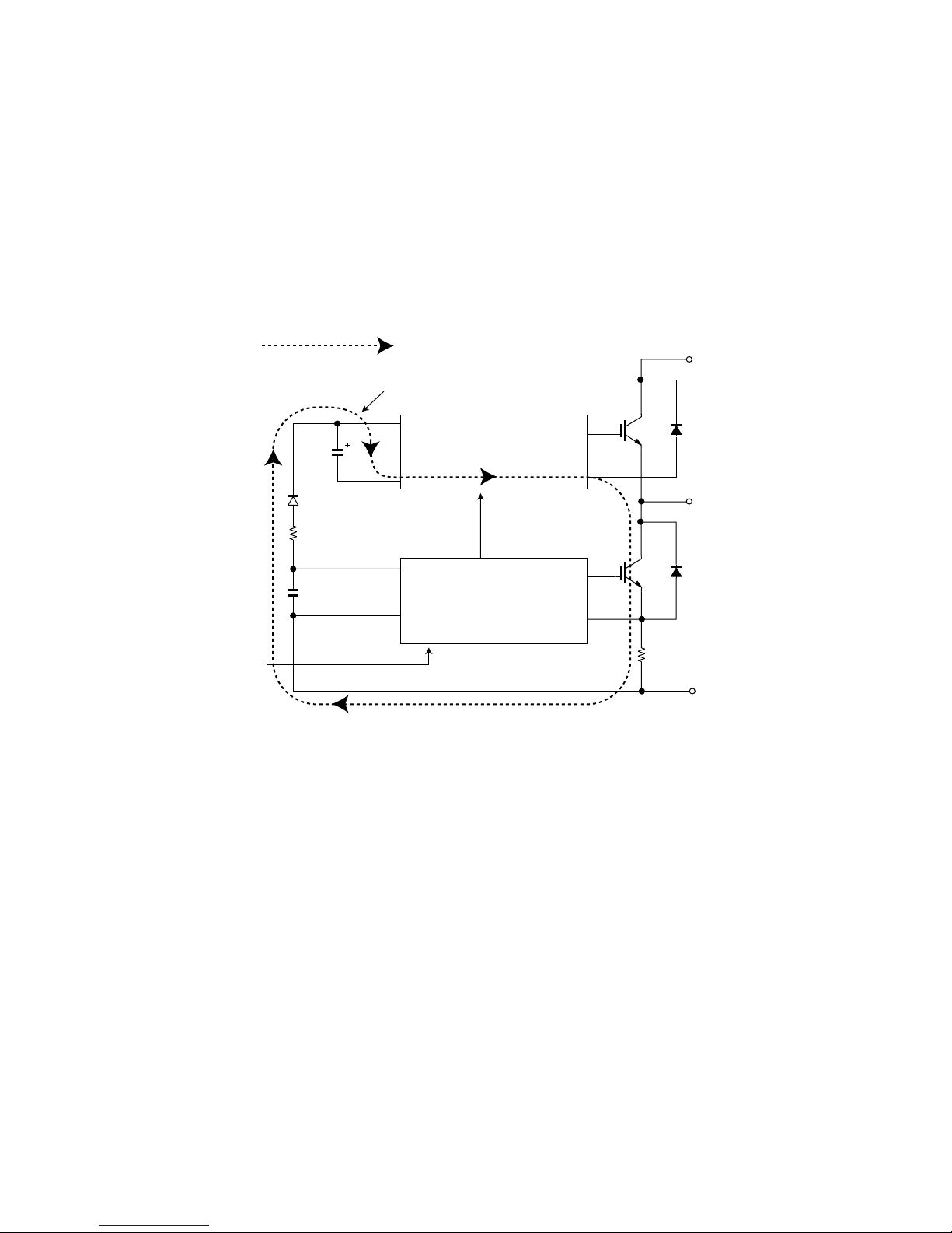
4.1. IPM drive power supply circuit
The power supply for the upper-phase IGBT (HU, HV, HW) drive employs a bootstrap system, and provides power to the upper-phase IC.
The 15-V power supply for the lower-phase IC is provided by the control printed circuit board (PCB).
4.1.1 Brief explanation of bootstrap system (single power drive system)
To supply power to the upper-phase IC, the microcomputer (IC1) turns ON the lower-phase IGBT (LU, LV, LW).
This results in a charging current that flows to the electrolytic capacitor of each upper-phase IC input and charges the bootstrap capacitor with a 15-V
current.
The power supply for the subsequent stages is charged while the lower-phase IGBT is ON in ordinary compressor drive control.
Initial charge period
VDB
Charging current group
Bootstrap capacitor
(HU,HV,HW)
HVIC
High-voltage-withstanding,
high-speed recovery diode
P(Vcc)
U,V,W,
V
D
VCIN(n)
(LU,LV,LW)
Bootstrapcircuit
LVIC
N-side
IGBT
N(GN
2 – 14
Page 19

AYXP12FRN
4.1.2 DC overcurrent detection circuit
When a current of about 25 A or higher flows through the shunt resistance (R49) on the control printed circuit board (PCB), the voltage at this resistance is input to IPM CIN pin (26). Then, the gate voltage of the lower-phase IGBT (LU, LV, LW) inside the IPM turns OFF to cut off the overcurrent. At
the same time, an L output of about 1.8 ms is generated from IPM Fo pin (24), and this results in an L input to overcurrent detection input pin (34) of
the microcomputer (IC1) and turns OFF the PWM signal output (IC1 pins (51) through (56)) to the IGBT gate.
Protection circuit status
(Lower phase)
Internal IGBT gate
Output current Ic (A)
Sense voltage relative
to shunt resistance
Error output Fo
SET
RESET
(About 22 A)
SC
a1
SC reference voltage
Delay by CR time constant circuit
About 1.8 ms
IPM overcurrent
detection circuit
CiN
26
FO
24
P
Shunt resistance
R49
N
Overcurrent
5V
IC1
34
0V
2 – 15
Page 20

AYXP12FRN
5. 120° energizing control (digital position detection control)
This control system detects the digital position detection signal and adjusts the rate of acceleration/deceleration accordingly.
The motor's induced voltage waveform is input to the comparator in the form of PWM-switched pulse waveform, and a position detection signal is
generated as a reference voltage equaling 1/2 of 280 VDC. However, since there is no induced voltage waveform when the PWM waveform is OFF,
the microcomputer performs internal processing so that detection is enabled only when it is ON. Based on the detected position signal, actual PWM
waveform output timing is determined. Since it does not use a filter circuit, the detection accuracy is high.
The microcomputer performs internal processing to cancel spike voltage during the regenerative process.
Furthermore, even if the induced voltage is low, position detection is still possible, thus allowing sensor-less operation at low rotation speed in the initial stage of operation. This reduces the starting current and improves the IPM reliability.
Terminal voltage waveform
Reference voltage
(1/2 of DC voltage)
Spike voltage
(cancelled)
Comparator output waveform
(Position signal waveform)
2 – 16
Page 21

AYXP12FRN
AYXP12FRN
CHAPTER 3. FUNCTION AND OPERATION OF PROTECTIVE PROCEDURES
Service Manual
[1] PROTECTION DEVICE FUNCTIONS AND OPERATIONS
Function Operation Self-diagnosis
result display
Description Detection period Reset condition Indoor
1 Indoor unit fan lock Operation stops if there is no
Indoor unit fan rotation speed error
2 Indoor unit freeze
prevention
3 2-way valve freeze
prevention
4 Indoor unit heat
exchanger overheat shutdown
5 Outdoor unit heat
exchanger overheat shutdown
6 Compressor dis-
charge overheat
shutdown
7 Dehumidifying oper-
ation temporary
stop
8 DC overcurrent
error
input of rotation pulse signal from
indoor unit fan motor for 1 minute.
Operation stops if rotation pulse
signal from indoor unit fan indicates abnormally low speed
(about 300 rpm or slower).
Compressor stops if temperature
remains below 0°C for 4 minutes.
Compressor stops if temperature
of outdoor unit 2-way valve
remains below 0°C for 10 continuous minutes during cooling or
dehumidifying operation.
Operating frequency lowers if
indoor unit heat exchanger temperature exceeds overheat temperature during heating
operation.
Compressor stops if indoor unit
heat exchanger temperature
exceeds overheat temperature for
60 seconds at minimum frequency.
Overheat temperature setting
value indoor unit heat exchanger
thermistor temperature: about 45
to 54°C
Operation frequency lowers if outdoor unit heat exchanger temperature exceeds about 55°C during
cooling operation.
Compressor stops if outdoor unit
heat exchanger temperature
exceeds about 55°C for 120 seconds at minimum frequency.
Operating frequency lowers if
temperature of compressor
chamber thermistor (TH1) falls
below about 110°C.
Compressor stops if temperature
of compressor chamber thermistor (TH1) remains at about
110 °C (for 120 seconds in cooling
operation, or 60 seconds in heating operation) at minimum frequency.
Compressor stops if outside air
temperature thermistor is lower
than about 16°C during dehumidifying operation.
Compressor stops if electric current of about 25 A or higher flows
in IPM.
When indoor unit fan
is in operation
When indoor unit fan
is in operation
When in cooling or
dehumidifying operation
When in cooling or
dehumidifying operation
When in heating
operation
When in cooling or
dehumidifying operation
When compressor is
in operation
When in dehumidifying operation
When compressor is
in operation
Indoor
unit
error
display
Operation OFF or ON ✩2 Yes None
Operation OFF or ON ✩2 Yes None
Automatic reset when
heat exchanger temperature rises above
freeze prevention
temperature (2°C or
higher)
Automatic reset when
temperature of 2-way
valve rises above
10°C.
Automatic reset after
safety period (180
sec).
Automatic reset after
safety period (180
sec).
Automatic reset after
safety period (180
sec).
Automatic reset when
outside air temperature rises above
16°C.
Operation OFF or ON Yes ✩1Yes Yes
— None None
None Yes Yes
None Yes Yes
None Yes Yes
None Yes Yes
None Yes Yes
unit
Outdoor
unit
3 – 1
Page 22

AYXP12FRN
Function Operation Self-diagnosis
Description Detection period Reset condition Indoor
9 AC overcurrent
error
10 AC overcurrent
error in compressor
OFF status
11 AC maximum cur-
rent error
12 AC current defi-
ciency error
13 Thermistor installa-
tion error or 4-way
valve error
14 Compressor high
temperature error
15 Outdoor unit heat
exchanger thermistor short-circuit
error
16 Outdoor unit outside
air temperature
thermistor short-circuit error
17 Outdoor unit suction
thermistor short-circuit error
18 Outdoor unit 2-way
valve thermistor
short-circuit error
19 Outdoor unit heat
exchanger thermistor open-circuit
error
20 Outdoor unit outside
air temperature
thermistor open-circuit error
21 Outdoor unit suction
thermistor open-circuit error
22 Outdoor unit 2-way
valve thermistor
open-circuit error
23 Outdoor unit dis-
charge thermistor
open-circuit error
24 Serial signal error Power relay turns OFF if indoor
Operating frequency lowers if
compressor AC current exceeds
peak control current value. Compressor stops if compressor AC
current exceeds peak control current value at minimum frequency.
Indoor and outdoor units stop if
AC current exceeds about 3 A
while compressor is in non-operation status.
Compressor stops if compressor
AC current exceeds 17 A.
Compressor stops if operating
frequency is 50 Hz or higher and
compressor AC current is about
2.0 A or lower.
Compressor stops if high and low
values of temperatures detected
by outdoor unit heat exchanger
thermistor (TH2) and 2-way valve
thermistor (TH5) do not match
operating cycle.
Compressor stops if compressor
chamber thermistor (TH1)
exceeds about 114°C, or if there
is short-circuit in TH1.
Compressor stops if there is
short-circuit in outdoor unit heat
exchanger thermistor (TH2).
Compressor stops if there is
short-circuit in outdoor unit outside air temperature thermistor
(TH3).
Compressor stops if there is
short-circuit in outdoor unit suction thermistor (TH4).
Compressor stops if there is
short-circuit in outdoor unit 2-way
valve thermistor (TH5).
Compressor stops if there is
open-circuit in outdoor unit heat
exchanger thermistor (TH2).
Compressor stops if there is
open-circuit in outdoor unit outside air temperature thermistor
(TH3).
Compressor stops if there is
open-circuit in outdoor unit suction thermistor (TH4).
Compressor stops if there is
open-circuit in outdoor unit 2-way
valve thermistor (TH5).
Compressor stops if there is
open-circuit in outdoor unit discharge thermistor (TH1).
unit cannot receive serial signal
from outdoor unit for 8 minutes.
Compressor stops if outdoor unit
cannot receive serial signal from
indoor unit for 30 seconds.
result display
Indoor
unit
error
display
When compressor is
in operation
When compressor is
in non-operation
When compressor is
in operation
When compressor is
in operation
3 minutes after compressor startup
When in operation Operation OFF or ON Yes ✩1Yes Yes
At compressor startup
At compressor startup
At compressor startup
At compressor startup
At compressor startup
At compressor startup
At compressor startup
At compressor startup
At compressor startup
When in operation Operation OFF or ON
When in operation Reset after reception
Operation OFF or ON Yes ✩1Yes Yes
Replacement of
defective parts such
as IPM
Operation OFF or ON Yes ✩1Yes Yes
Operation OFF or ON Yes ✩1Yes Yes
Operation OFF or ON Yes ✩1Yes Yes
Operation OFF or ON Yes ✩1Yes Yes
Operation OFF or ON Yes ✩1Yes Yes
Operation OFF or ON Yes ✩1Yes Yes
Operation OFF or ON Yes ✩1Yes Yes
Operation OFF or ON Yes ✩1Yes Yes
Operation OFF or ON Yes ✩1Yes Yes
Operation OFF or ON Yes ✩1Yes Yes
Operation OFF or ON Yes ✩1Yes Yes
Operation OFF or ON Yes ✩1Yes Yes
(Automatic reset
when less than 8 minutes)
of serial signal
Yes ✩ 2Yes Yes
None None None
unit
Yes None
Outdoor
unit
3 – 2
Page 23

Function Operation Self-diagnosis
Description Detection period Reset condition Indoor
25 Compressor star-
tup error
26 Compressor rota-
tion error (at 120°
energizing)
27 Outdoor unit DC fan
error
28 PAM overvoltage
error
29 PAM clock error When power source frequency
30 IPM pin level error When Outdoor unit starts to run,
✩1—The outdoor unit restarts four times before the indoor unit error is displayed (complete shutdown).
✩2—A single error judgment results in the display of the indoor unit error (complete shutdown).
✩3—The outdoor unit restarts eight times before the indoor unit error is displayed (complete shutdown).
Compressor stops if compressor
fails to start up.
Compressor stops if there is no
input of position detection signal
from compressor or input is
abnormal.
Operation stops if there is no
input of rotation pulse signal from
outdoor unit fan motor for 30 seconds.
Compressor stops if DC voltage is
350 V or higher.
cannot be determined (at startup),
or when power source clock cannot be detected for 1 continuous
second (at startup).
MCU checks 6 control pin levels
of IPM. If MCU detects some pin
levels isn’t different from another
pin level. MCU doesn’t run Compressor.
At compressor startup
Compressor operating at 120° energizing
When outdoor unit
fan is in operation
When in operation Operation OFF or ON Yes ✩1Yes Yes
At compressor startup, when in operation
At compressor startup
Operation OFF or ON Yes ✩3Yes Yes
Operation OFF or ON Yes ✩3Yes Yes
Operation OFF or ON Yes ✩1Yes Yes
Compressor continues operation without stopping.
Operation OFF or ON Yes ✩1Yes Yes
AYXP12FRN
result display
Indoor
unit
error
display
None Yes Yes
unit
Outdoor
unit
[2] AIR CONDITIONER OPERATION IN THERMISTOR ERROR
1. Indoor unit
Item Mode Control opera-
Room temperature thermistor
(TH1)
Auto Operation mode
judgment
Cooling Frequency control Room becomes
Dehumidifying Room tempera-
ture memory
Frequency control
Heating Frequency control Room does not
tion
When resistance is low
(temperature
judged higher
than actual)
Cooling mode is
activated even if
room temperature is low.
too cold.
Normal operation. Room tempera-
become warm.
Short-circuit When resis-
Cooling mode is
activated in most
cases.
Air conditioner
operates in full
power even when
set temperature is
reached.
ture is stored in
memory as
31.0°C, and compressor does not
stop.
Hot keep status
results immediately after operation starts.
Frequency does
not increase
above 30 Hz (40
Hz).
Open-circuit
tance is high
(temperature
judged lower
than actual)
Heating mode is
activated even if
room temperature is high.
Room does not
become cool.
Normal operation. Room tempera-
Room becomes
too warm.
Heating mode is
always activated.
Compressor does
not operate.
ture is stored in
memory as
18.5°C, and compressor does not
operate.
Air conditioner
operates in full
power even when
set temperature is
reached.
3 – 3
Page 24

AYXP12FRN
Item Mode Control opera-
Heat exchanger
thermistor (TH2)
Cooling
Dehumidifying
Heating Cold air preven-
2. Outdoor unit
Item Mode Control opera-
Compressor
chamber thermistor (TH1)
Heat exchanger
thermistor (TH2)
Outside air temperature thermistor (TH3)
Suction pipe thermistor (TH4)
Cooling
Dehumidifying
Heating
Cooling
Dehumidifying
Heating Expansion valve
Auto Operation mode
Cooling
Dehumidifying
Heating Rating control
Cooling
Dehumidifying
Heating Expansion valve
tion
Freeze prevention
tion
tion
Expansion valve
control and compressor protection
Outdoor unit heat
exchanger overheat prevention
control
Defrosting
judgment
Operation not
affected
Defrosting
Expansion valve
control
control
When resistance is low
(temperature
judged higher
than actual)
Indoor unit evaporator may
freeze.
Cold air prevention deactivates
too soon and cold
air discharges.
When resistance is low
(temperature
judged higher
than actual)
Compressor
operates, but
room does not
become cool or
warm (expansion
valve is open).
Compressor
operates at low
speed or stops.
Defrosting operation is not activated as needed,
and frost accumulates on outdoor
unit (expansion
valve is closed).
Cooling mode is
activated even if
room temperature is low.
Normal operation. Outdoor unit ther-
Defrosting operation is activated
unnecessarily.
Compressor
operates, but
room does not
become cool
(expansion valve
is open).
Compressor
operates, but
room does not
become warm
(expansion valve
is open).
Short-circuit When resis-
Indoor unit evaporator may
freeze.
Compressor
operates at low
speed or stops,
and frequency
does not
increase.
Short-circuit When resis-
Compressor high
temperature error
indication.
Outdoor unit thermistor short-circuit error
indication.
Outdoor unit thermistor short-circuit error
indication.
Outdoor unit thermistor short-circuit error
indication.
mistor short-circuit error
indication.
Outdoor unit thermistor short-circuit error
indication.
Outdoor unit thermistor short-circuit error
indication.
Outdoor unit thermistor short-circuit error
indication.
tance is high
(temperature
judged lower
than actual)
Compressor
stops occasionally.
Cold air prevention deactivates
too slow.
tance is high
(temperature
judged lower
than actual)
Layer short-circuit or open-circuit may result in
compressor in
normal operation.
Normal operation. Outdoor unit ther-
Defrosting operation is activated
unnecessarily,
and room does
not become warm
(expansion valve
is open).
Heating mode is
activated even if
room temperature is high.
Normal operation. Outdoor unit ther-
Defrosting operation is not activated, and frost
accumulates on
outdoor unit.
Frost accumulates on evaporator inlet section,
and room does
not become cool
(expansion valve
is closed).
Frost accumulates on expansion valve outlet
section, and room
does not become
warm (expansion
valve is closed).
Open-circuit
Compressor does
not operate.
Cold air prevention does not
deactivate, and
indoor unit fan
does not rotate.
Open-circuit
Outdoor unit thermistor open-circuit error
indication.
mistor open-circuit error
indication.
Outdoor unit thermistor open-circuit error
indication.
Outdoor unit thermistor open-circuit error
indication.
mistor open-circuit error
indication.
Outdoor unit thermistor open-circuit error
indication.
Outdoor unit thermistor open-circuit error
indication.
Outdoor unit thermistor open-circuit error
indication.
3 – 4
Page 25

AYXP12FRN
Item Mode Control opera-
tion
When resistance is low
Short-circuit When resis-
(temperature
judged higher
than actual)
2-way valve thermistor (TH5)
Cooling
Dehumidifying
Expansion valve
control
Frost accumulates on indoor
unit evaporator
and room does
Outdoor unit thermistor short-circuit error
indication.
not become cool
(expansion valve
is closed).
Heating Operation not
affected
Normal operation. Outdoor unit ther-
mistor short-cir-
cuit error
indication.
[3] THERMISTOR TEMPERATURE CHARACTERISTICS
1. Indoor unit thermistor temperature characteristics
TH1 TH2
CN4
43
-
+
Room temperature thermistor TH1 (yellow)
Resistance at 25 : 10 k
Resistance
(K )
K
100
80
60
40
20
Heat exchanger thermistor TH2 (orange)
Resistance at 25 : 15 k
21
-
+
TesterTester
CN4
Open-circuit
tance is high
(temperature
judged lower
than actual)
Compressor
operates, but
room does not
become cool
Outdoor unit thermistor open-circuit error
indication.
(expansion valve
is open).
Normal operation. Outdoor unit ther-
mistor open-cir-
cuit error
indication.
0
-10
010203040
TH1 Room temperature thermistor
TH2 Heat exchanger thermistor
Thermistor
Room temperature
Heat exchanger
Symbol
TH1
(CN4)
TH2
(CN4)
Temperature( )
Color
Yellow
Orange
Before measuring resistance,
disconnect connectors as
shown above.
3 – 5
Page 26

AYXP12FRN
2. Outdoor unit thermistor temperature characteristics
500K
400K
Resistance
(K )
300K
200K
100K
0
-20 0 20 60 80 100 120
TH1 Compressor thermistor
Compressor thermistor
Heat exchanger thermistor
Outdoor air temperature thermistor
Suction thermistor
2-way valve thermistor
Thermistor
Resistance at 25
52.76 k
Temperature( )
Connector
CN8
110
+
-
5.8K
Tester
4.17K
3.06K
2.28K
No.
TH1
TH2
TH3
TH4
TH5
1.72K
Resistance
(K )
Connector
No. (1) - No. (2)
No. (3) - No. (4)
No. (5) - No. (6)
No. (7) - No. (8)
No. (9) - No. (10)
Connector
CN8
110
+
-
40K
Resistance at 0
30K
14.57 k
20K
10K
0
-20 0 20 6040
Tester
(In case of TH2 heat exchanger thermistor)
Resistance at 25
4.431 k
TH2 TH5
Temperature( )
TH2 Heat exchanger thermistor
TH3 Outdoor air temperature thermistor
TH4 Suction thermistor
TH5 2-way valve thermistor
Color
Before measuring resistance,
Red
disconnect connectors from PWB.
Orange
Green
Black
Yellow
3 – 6
Page 27

AYXP12FRN
Connect with IC clip
Test mode cooling at 40 Hz
[4] HOW TO OPERATE THE OUTDOOR UNIT INDEPENDENTLY
1. Cooling in 40 Hz fixed mode
To operate the outdoor unit independently, short-circuit the sections indicated by arrows in the diagram below with an adapter, and apply 230 VAC
between (1) and (N) on the terminal board of the outdoor unit. This allows the outdoor unit to be operated in cooling mode independently.
(Do not operate the outdoor unit in this condition for an extended period of time.)
Short-circuit negative terminal of
Connect with IC clip
Test mode cooling at 40 Hz
C9C10
(L2)
capacitor (C33) and jumper wire
(JP16) using IC clip, etc.
[5] GENERAL TROUBLESHOOTING CHART
1. Indoor unit does not turn on
Main cause Inspection method Normal value/condition Remedy
Cracked PWB.
(Cracked pattern)
Open-circuit in FU1 (250 V, 3 A),
FU2 (250 V, 3 A)
Check visually. There should be no cracking in
PWB or pattern.
Check melting of FU1, FU2. There should be no open-circuit. Replace PWB.
Replace PWB.
2. Indoor unit fan does not operate
Main cause Inspection method Normal value/condition Remedy
Open-circuit in heat exchanger
thermistor (TH2) (in heating operation)
Disconnected heat exchanger
thermistor (TH2) (in heating operation)
Measure thermistor resistance
(dismount for check).
Inspect connector on PWB.
Check thermistor installation condition.
3. Indoor unit fan speed does not change
Main cause Inspection method Normal value/condition Remedy
Remote control not designed to
allow fan speed change.
Check operation mode. Fan speed should change except
4. Remote control signal is not received
Main cause Inspection method Normal value/condition Remedy
Batteries at end of service life. Measure battery voltage. 2.5 V or higher (two batteries in
Batteries installed incorrectly. Check battery direction. As indicated on battery compart-
Lighting fixture is too close, or fluorescent lamp is burning out.
Use Sevick light (Hitachi). Check if Sevick light (Hitachi) is
Operating position/angle is inappropriate.
Open-circuit or short-circuit in wiring of light receiving section.
Defective light receiving unit. Check signal receiving circuit
Turn off light and check. Signal should be received when
used.
Operate within range specified in
manual.
Check if wires of light receiving
section are caught.
(measure voltage between terminals 2 and 3 of connector
BCN3B).
– 1 Replace thermistor.
There should be no open-circuit
or faulty contact.
Thermistor should not be disconnected.
during dehumidifying operation,
ventilation, light dehumidifying
operation, internally normal operation
series connection)
ment.
light is turned off.
Signal may not be received
sometimes due to effect of Sevick
light.
Signal should be received within
range specified in manual.
Wires of light receiving section
should not have any damage
caused by pinching.
Tester indicator should move
when signal is received.
Replace thermistor.
Install correctly.
Explain to user.
Install new batteries.
Install batteries in indicated direction.
Change light position or install
new fluorescent lamp.
Replace light or change position.
Explain appropriate handling to
user.
Replace wires of light receiving
section.
Replace PWB.
3 – 7
Page 28

AYXP12FRN
Main cause Inspection method Normal value/condition Remedy
Dew condensation on light receiving unit.
5. Louvers do not move
Main cause Inspection method Normal value/condition Remedy
Caught in sliding section. Operate to see if louvers are
Disconnected connector (DCNC,
DCND on relay PWB, louver
motor side)
Contact of solder on PWB
(connector section on PWB)
6. There is noise in TV/radio
Main cause Inspection method Normal value/condition Remedy
Grounding wires not connected
properly.
TV/radio is placed too close to
outdoor unit.
Other than above. Check for radio wave interfer-
7. Malfunction occurs
Check for water and rust. Signal should be received within
caught in place.
Inspect connectors. Connectors or pins should not be
Check visually. There should not be solder con-
Check grounding wire connections.
Check distance between TV/radio
and outdoor unit.
ence. (See page )
range specified in manual.
Louvers should operate smoothly. Remove or correct catching sec-
disconnected.
tact.
Grounding wires should be connected properly.
If TV/radio is placed too close, it
may become affected by noise.
Take moisture-proof measure for
lead wire outlet of light receiving
section.
tion.
Install correctly.
Correct contacting section.
Connect grounding wires properly.
Move TV/radio away from outdoor
unit.
Main cause Inspection method Normal value/condition Remedy
Malfunction caused by noise. Check for radio wave interfer-
ence. (See page )
8. Compressor does not start
Main cause Inspection method Normal value/condition Remedy
Erroneous inter-unit connection. Check wiring between indoor and
outdoor units.
Damaged IPM. Check IPM continuity. See [IPM check method] on page
Dried-up electrolytic capacitor. Check electrolytic capacitor. See [Inverter electrolytic capaci-
Blown outdoor unit fuse. Check 20-A fuse.
Check 15-A fuse.
Power supply voltage is too low. Measure power supply voltage
during startup.
Compressor lock. Supply current and touch com-
pressor cover (sound absorbing
material) to check if operation
starts.
Terminal board 1-N: 230 VAC, 50
Hz
Terminal board 2: serial signal
8-3.
tor (C9, C10) check method] on
page 8-2.
Fuse should not be blown. Replace fuse/diode bridge.
230±10 VAC, 50 Hz Make sure that power supply volt-
Compressor should start normally.
9. Operation stops after a few minutes and restarts, and this process repeats
Correct wiring.
Replace IPM.
Replace electrolytic capacitor.
Replace fuse.
Replace outdoor unit PWB
assembly.
age is 180 V or higher.
Apply external impact to compressor.
Replace compressor.
Main cause Inspection method Normal value/condition Remedy
Dried-up electrolytic capacitor. Measure 320-VDC line voltage. 250 V or higher. Replace electrolytic capacitor.
Layer short-circuit in expansion
valve coil.
CAUTION: If fuse FU1/FU4/FU5 (outdoor unit control circuit board) is blown, be careful of charging voltage in inverter electrolytic capacitor C9, C10.
To discharge stored electricity, unplug the power cord and connect the plug of a soldering iron (100VAC, 50W) between the positive and
negative terminals of inverter electrolytic capacitor C9, C10.
Measure resistance. 46±3Ω in each phase (at 20°C) Replace coil.
3 – 8
Page 29

AYXP12FRN
[6] MALFUNCTION (PARTS) CHECK METHOD
1. Procedure for determining defective outdoor unit IPM/compressor
The following flow chart shows a procedure for locating the cause of a malfunction when the compressor does not start up and a DC overcurrent indication error occurs.
Connect power cord
to AC outlet.
Using remote control,
operate air conditioner
so that compressor
starts.
After about
20 seconds
NO
Is there 230 VAC
between (1) and (N)
on outdoor unit PCB?
YES
Is LED1 on outdoor
unit flashing?
Check inter-unit wiring.
Check indoor unit PWB.
NO
Does LED1 remain lit?
No
(unlit)
Is there 320 VDC between
pins IPM (31) and (35)?
Check posistor (PTC1)
(about 40 at 25 ).
Check IPM.
Check fan motor.
Check outdoor unit PCB.
NO
Check wiring.
Check PAM IGBT (Q5).
YES
Compressor starts up.
Immediately
after startup
Does LED1 indicate
DC overcurrent error?
NO
Does LED1 indicate
rotation error?
NO
Normal
YES
Serial signal error.
Check inter-unit wiring.
Check indoor and
outdoor unit PWBs.
YES
Replace outdoor unit
PWB.
Check compressor.
2/3-way valve closed.
Refrigerant shortage.
Outdoor unit PWB.
YES YES
15/5 V display section.
Voltage OK.
NO
Replace outdoor unit PWB.
YES
+13 V, +15 V on PWB.
YES
Replace outdoor unit PWB.
Replace expansion valve.
Replace outdoor unit
NO
Replace compressor.
NO
Disconnect expansion
valve connector.
YES
OK
+13 V on PWB.
End.
NO
Replace outdoor unit PWB.
3 – 9
Page 30

AYXP12FRN
2. Procedure for determining defective expansion valve
Measure resistance in expansion valve coil.
6
Checker
5.6K
5
4
Connector
J.S.T. XAP-06V-1
Terminal
SXA-001T-P0.6
LED
(red)
5.6K
5.6K
32
1
5.6K
Replace control PWB.
Normal resistance between red
terminal of expansion valve
lead wire and each terminal:
about 46 (at 20 )
YES
Insert checker shown at left into
connector (CN12) on control PWB, and
operate air conditioner.
NO
Do LEDs on checker light in orderly
sequence
(lighting of 1 LED => lighting of 2 LEDs)
YES
If frost accumulates on 2-way valve after 10 to 20
minutes of cooling operation, then thermistors with
yellow and black lead wires may be defective. Check
these thermistors.
&GHGEVKXGVJGTOKUVQT
NO
6JGTOKUVQTUKP
PQTOCNEQPFKVKQP
4GRNCEGVJGTOKUVQTCUUGODN[
4GRNCEGGZRCPUKQP
XCNXGCUUGODN[
3. Diode bridge check method
Turn off the power and let the inverter electrolytic capacitor (C9, C10) discharge completely. Then use a tester and check continuity.
When using a digital tester, the (+) and (-) tester lead wires in the table must be reversed.
Needle-type tester
45 B
Value in ( ) is for digital tester.
Normal resistance value
(several M )
4. Inverter electrolytic capacitor (C9, C10) check method
Turn off the power, let the inverter electrolytic capacitor (C9, C10) discharge completely, and remove the capacitor from the control printed circuit
board (PWB). First, check the case for cracks, deformation and other damages. Then, using a needle-type tester, check continuity.
Determination of normal condition
The tester needle should move on the scale and slowly returns to the original position. The tester needle should move
in the same way when polarities are reversed. (When measurement is taken with the polarities reversed, the tester
needle exceeds the scale range. Therefore, let the capacitor discharge before measurement.)
3 – 10
Page 31

AYXP12FRN
0
5. IPM check method
Turn off the power, let the large capacity electrolytic capacitor (C10) discharge completely, and dismount the IPM. Then, using a tester, check leak
current between C and E.
When using a digital tester, the (+) and (-) tester lead wires in the table must be reversed.
Needle-type tester Normal resistance value
(-) (+)
PN∞
U
(several MΩ)
V
W
5.1. IPM internal circuit diagram
Needle-type tester Normal resistance value
(-) (+)
UN∞
V
(several MΩ)
W
Values in ( ) are for digital tester.
2
&+2+2/
7(5
7($
8
8
$
8
*8+%
%%
8
2
8
0
8
%(1 %+0
01
%+0
8
%(1
*1
*1
8
5
8
$
8
7
5
8
$
8
*1
9
176
5
8
7
176
8
176
9
.8+%
*8+%
8($
8
%%
8
+0
%1/
2
2
8(5
8
8
8
+0
%1/
2
7
*8+%
%%
8
+0
%1/
9(5
9($
2
2
9
8
%%
8
0
8
708090(Q
0
7
0
0
8
9
)0&
1
0%
(
8
[7] OUTDOOR UNIT CHECK METHOD
After repairing the outdoor unit, conduct the following inspection procedures to make sure that it has been repaired completely. Then, operate the
compressor for a final operation check.
1. Checking procedures
No
.
1 Preparation Disconnect compressor cords (white,
2 Inverter DC power supply
voltage check
3 IPM circuit check Check that 3 lamps (load) light.
Item Check method Normal value/condition Remedy
orange, red: 3 wires) from compressor terminals, and connect simulated
load (lamp used as load).
Operate air conditioner in cooling or
heating test operation mode.
Measure DC voltage between IPM
pins (31) and (35).
Check position detection voltage (+15
V, 5 V) on control PWB.
320 VDC Replace control PWB.
Replace diode bridge.
Correct soldered section of Fasten tabs (T1, T2, T5 - T3) on control PWB and IMP (S, C, R).
(Repair solder cracks.)
Each voltage should be normal.
Replace control PWB.
All 3 lamps (load) should light with
same intensity.
3 – 11
Page 32

AYXP12FRN
No
.
4 Compressor check Measure compressor coil resistance
5 Expansion valve check Measure expansion valve coil resis-
6 Final check Turn off power, and connect compres-
Item Check method Normal value/condition Remedy
(for each phase of U, V and W).
Use multi-meter or digital tester capable of displaying two digits right of the
decimal point (0.01Ω).
tance.
sor cords to compressor.
Operate air conditioner.
Measure DC voltage between IPM
pins (31) and (35).
2. Troubleshooting of outdoor unit electric components
Does LED light?
YES
NO
Is 230 V applied
between 1 and
N on outdoor
unit terminal
board?
Check indoor
unit.
NO
YES NO
Is voltage between
IPM pins (31) and
(35) 320 V or
higher?
Resistance value at 20°C --- 0.65Ω Correct connections at compres-
sor terminals.
Replace compressor.
Each phase 46±3Ω (at 20°C) Replace expansion valve.
Compressor should operate normally.
200 VDC or higher.
5/ Short-circuit in DC fan motor
Short-circuit in IPM
Short-circuit in diode bridge
Blown fuse
Defective electrolytic capacitor
YES
Wire disconnection, PWB pattern damage
Short-circuit in PAM IGBT (Q5)
Replace control PWB.
Replace outdoor unit thermistor.
Replace compressor (in case of
compressor lock).
Does LED flash?
YES
Normal
NO
Is switching power
supply output of
13 VDC, 15 VDC
produced?
YES
Is 5 VDC output
produced?
YES
NO
NO
Defective switching power supply circuit
Malfunction of 3-terminal regulator IC4, IC1
Short-circuit in expansion valve coil
Malfunction of transistor array IC7
Solder contact or other problems
Malfunction of 3-terminal regulator IC4, IC1
Microcomputer oscillator error
Malfunction of microcomputer reset IC
Malfunction of microcomputer
Malfunction of serial signal circuit
Check wiring between indoor and outdoor units.
3 – 12
Page 33

AYXP12FRN
3. Caution in checking printed circuit boards (PWB)
3.1. Non-insulated control circuit
The GND terminals of the low-voltage circuits (control circuits for microcomputer and thermistors and drive circuits for expansion valve and relays) on
the control printed circuit board (PWB) are connected to the compressor drive power supply (320-VDC negative terminal). Therefore, exercise utmost
caution to prevent electric shock.
If a measuring instrument used for the test is grounded, its chassis (ground) has the same electric potential as the 0-V probe. Since non-insulated circuits have the following voltage potential difference from the ground, connection of the grounding wire results in a short-circuit between the 0-V line
and the ground, thus allowing an excessive current to flow to the tester to cause damage.
If the sheaths of the thermistor lead wires or expansion valve lead wires inside the outdoor unit become damaged due to pinching by the front panel
or other metal parts or contacting a pipe, a high voltage can flow and destroy the circuits. To prevent these problems, carefully conduct assembly
work.
Outdoor unit circuits
Terminal board
Reactor
2
Point (E)
AC230V
320-VDC line
0-V line
+
-
IPM
M
1
Compressor motor
Ground
0-V line
Point (F)
3
Voltage at point (E)
+ 160V
Ground voltage
320V
- 160V
0-V line voltage (point (F))
Do not touch the
cabinet or bring metal
parts into contact with
the cabinet.
Danger!!
Do not connect
the grounding
wire.
Reason
The oscilloscope (chassis ground) has the same electric potential as the 0-V probe. The
entire electronic control section of the outdoor unit has a voltage potential difference from
the ground as shown in the above diagram. When the oscilloscope is set up, the 0-V line
and the ground voltage (ground) will be short-circuited, resulting in an excessive current
flow to cause damage to the oscilloscope or indoor electric circuits.
3 – 13
Page 34

AYXP12FRN
[8] TROUBLESHOOTING GUIDE
1. Self-Diagnosis Function and Display Mode
To call out the content of the self-diagnosis memory, hold down the emergency operation button for more than 5 seconds when the indoor unit is not
operating.
• The number of indications displayed by the LEDs on the outdoor unit differs from that for the 2001 cooling unit models (for detailed display of malfunction information).
The display of malfunction No. differs from that of the 2001 cooling unit models. To show detailed malfunction information, two types of numbers
flash alternately. (example: "21" ←→ "-0")
1) The content of the self-diagnosis memory can be called out and displayed on the seven-segment display section on the indoor unit. (The error
data cannot be called out for display by the LED on the outdoor unit.)
2) If the power cord is unplugged from the AC outlet or the circuit breaker is turned off, the self-diagnosis memory loses the stored data.
a) The self-diagnosis display function of the indoor unit indicates the content of diagnosis by showing the error main category (number) and the
error sub-category (-number) alternately in 1-second intervals on the seven-segment display section of the indoor unit.
Example of self-diagnosis display on indoor unit: Compressor high-temperature error
'TTQTOCKPECVGIQT[ 'TTQTUWDECVGIQT[
b) The self-diagnosis display function of the outdoor unit indicates the error information by flashing LED1 on the outdoor unit according to the con-
tent of self-diagnosis.
The self-diagnosis display function of the outdoor unit is active only for about 3 to 10 minutes after self-diagnosis is performed during operation,
and the display returns to normal condition after this display period.
The content of self-diagnosis cannot be called out by the self-diagnosis display function of the outdoor unit.
Example of self-diagnosis display on outdoor unit: Compressor high-temperature error
ON
OFF
c) The content of diagnosis is transferred to the indoor unit via serial communication, but it does not trigger a complete shutdown operation.
: Flashes in 2-sec intervals (normal), : On, : Off, : Flashes 3 times in 0.2-sec intervals (When LED1 on the outdoor unit flashes in 2-sec
intervals, the outdoor unit is in normal condition.)
Nor-
mal
flash-
ing
Malfunction
No. dis-
played on
main unit
display sec-
tion *1
Sub-
Main
cate-
cate-
gory
gory
00 Normal – –
Status of
indoor/
outdoor
units
Indoor/
outdoor
units in
operation
Indoor/
outdoor
units in
complete
shutdown
Indication
by LED1
on out-
door unit
*2
1 time 1 -0 Outdoor unit
1 sec 1 sec 1 sec 1 sec 1 sec1 sec0.6 sec 0.6 sec0.6 sec 0.6 sec 1 sec
Content of diagnosis Inspection location/method Remedy
Main category Sub-category
Heat exchanger
thermistor
short-circuit
-1 Outside tempera-
-2 Suction thermistor
-3 2-way valve ther-
thermistor short-cir-
cuit error
ture thermistor
short-circuit error
short-circuit error
mistor short-circuit
error
(1) Measure resistance of the
outdoor unit thermistors.
(TH2 to TH5: Approx. 4.4
kΩ at 25°C)
(2) Check the lead wire of the
outdoor unit thermistor for
torn sheath and short-circuit.
(3) No abnormality found in
above inspections (1) and
(2).
1 sec 1 sec
(1) Replace the outdoor
unit thermistor assembly.
(2) Replace the outdoor
unit thermistor assembly.
(3) Replace the outdoor
unit control PWB
assembly.
3 – 14
Page 35

AYXP12FRN
Status of
indoor/
outdoor
units
Indoor/
outdoor
units in
complete
shutdown
Indoor
unit in
operation
Outdoor
unit in
temporary stop
Indoor
unit in
operation
Outdoor
unit in
temporary stop
Indoor/
outdoor
units in
complete
shutdown
Indication
by LED1
on out-
door unit
*2
2 times 2 -0 Cycle tempera-
3 times 3 -0 Dry operation Temporary stop due
5 times 5 -0 Outdoor unit
Malfunction
No. dis-
played on
main unit
display sec-
tion *1
Sub-
Main
cate-
cate-
gory
gory
-1 Temporary stop due
-2 Temporary stop due
-3 Temporary stop due
-4 Temporary stop due
-1 Outside tempera-
-2 Suction thermistor
-3 2-way valve ther-
-4 Discharge ther-
Content of diagnosis Inspection location/method Remedy
Main category Sub-category
ture
thermistor
open-circuit
Compressor high-
temperature error
to compressor dis-
charge overheat *3
to outdoor unit heat
exchanger overheat
*3
to outdoor unit heat
exchanger overheat
*3
to 2-way valve
freeze *3
to dehumidifying
operation *3
Heat exchanger
thermistor open-cir-
cuit error
ture thermistor
open-circuit error
open-circuit error
mistor open-circuit
error
mistor open-circuit
error
(1) Check the outdoor unit air
outlet for blockage.
(2) Check if the power supply
voltage is 90 V or higher at
full power.
(3) Check the pipe connec-
tions for refrigerant leaks.
(4) Measure resistance of the
outdoor unit compressor
thermistor.
(TH1: Approx. 53 kΩ at
25°C)
(5) Check the expansion
valve for proper operation.
(Temporary stop for cycle protection)
(Temporary stop for cycle protection)
(Temporary stop for cycle protection)
(Temporary stop for cycle protection)
(Temporary stop for cycle protection)
(1) Check connector CN8 of
the outdoor unit thermistor for secure installation.
(2) Measure resistance of out-
door thermistors TH1 to
TH5.
(3) Check the lead wires of
thermistors TH1 through
TH5 on the outdoor unit
control PWB for open-circuit.
(4) No abnormality found in
above inspections (1)
through (3).
(1) Ensure unobstructed
air flow from the outdoor unit air outlet.
(2) Connect power sup-
ply of proper voltage.
(3) Charge the specified
amount of refrigerant.
(4) Replace the outdoor
unit compressor thermistor assembly.
(5) Replace the expan-
sion valve coil, expansion valve or outdoor
unit control PWB
assembly.
–
–
–
–
–
(1) Correct the installa-
tion.
(2) Replace the outdoor
unit thermistor assembly.
(3) Replace the outdoor
unit thermistor assembly.
(5) Replace the outdoor
unit control PWB
assembly.
3 – 15
Page 36

AYXP12FRN
Status of
indoor/
outdoor
units
Indoor/
outdoor
units in
complete
shutdown
Indoor/
outdoor
units in
complete
shutdown
Indoor/
outdoor
units in
complete
shutdown
Indication
by LED1
on out-
door unit
*2
6 times 6 -0 Outdoor unit DC DC overcurrent error (1) IPM continuity check (1) Replace the outdoor
7 times 7 -0 Outdoor unit AC AC overcurrent error (1) Check the outdoor unit air
9 times 9 -0 Outdoor unit
Malfunction
No. dis-
played on
main unit
display sec-
tion *1
Sub-
Main
cate-
cate-
gory
gory
-1 IPM pin level error Check the IPM is attached
-1 AC overcurrent error
-2 AC maximum cur-
-3 AC current defi-
-3 Torque control error (1) Check if the refrigerant
Content of diagnosis Inspection location/method Remedy
Main category Sub-category
(2) Check the IPM and heat
sink for secure installation.
(3) Check the outdoor unit fan
motor for proper rotation.
(4) No abnormality found in
above inspections (1)
through (3).
(5) No abnormality found in
above inspections (1)
through (4).
correctly to the outdoor
unit control PWB.
outlet for blockage.
(2) Check the outdoor unit fan
for proper rotation.
(1) IPM continuity check (1) Replace the outdoor
in OFF status
(1) Check the outdoor unit air
outlet for blockage.
(2) Check the outdoor unit fan
for proper rotation.
(1) Check if there is an open-
circuit in the secondary
winding of the current
transformer of the outdoor
unit control PWB.
(2) Check if the refrigerant
volume is abnormally low.
(3) Check if the refrigerant
flows properly.
(1) Check to make sure out-
door unit thermistor TH2
(heat exchanger) and TH5
(2-way valve) are installed
in correct positions.
(2) Measure resistance of
thermistors TH1 and TH5.
(3) Check the 4-way valve for
proper operation.
(4) No abnormality found in
above inspections (1)
through (3).
volume is abnormally low.
(2) Check the 4-way valve for
proper operation.
(3) check to see compressor
type is correct.
cooling/heating
switchover
rent error
ciency error
Thermistor installa-
tion error or 4-way
valve error
unit control PWB
assembly.
(2) Correct the installa-
tion (tighten the
screws).
(3) Replace the outdoor
unit fan motor.
(4) Replace the outdoor
unit control PWB
assembly.
(5) Replace the compres-
sor.
Replace the outdoor
unit control PWB
assembly.
(1) Ensure unobstructed
air flow from the outdoor unit air outlet.
(2) Check the outdoor unit
fan motor.
unit control PWB
assembly.
(1) Ensure unobstructed
air flow from the outdoor unit air outlet.
(1) Check the outdoor unit
fan motor.
(1) Replace the outdoor
unit control PWB
assembly.
(2) Charge the specified
amount of refrigerant.
(3) Correct refrigerant
clogs.
(2-way valve, 3-way
valve, pipe, expansion valve)
(1) Correct the installa-
tion.
(2) Replace the ther-
mistor assembly.
(3) Replace the 4-way
valve.
(4) Replace the outdoor
unit control PWB
assembly.
(1) Change the specified
amount of refrigerant.
(2) Replace the 4-way
valve.
(3) Replace the compres-
sor with the correct
part.
3 – 16
Page 37

AYXP12FRN
Status of
indoor/
outdoor
units
Indoor/
outdoor
units in
complete
shutdown
Indoor/
outdoor
units in
complete
shutdown
Indoor/
outdoor
units in
complete
shutdown
Indoor/
outdoor
units in
operation
Indoor
unit in
operation
Outdoor
unit in
complete
shutdown
Indication
by LED1
on out-
door unit
*2
11
times
13
times
14
times
Malfunction
No. dis-
played on
main unit
display sec-
tion *1
Sub-
Main
cate-
cate-
gory
gory
11 -0 Outdoor unit DC
13 -0 DC compressor Compressor startup
-1 Compressor rota-
14 -0 Outdoor unit
-1 PAM clock error (1) Check the PAM clock for
17 -0 Wires between
18 -0 Serial short-circuit (1) Check the wires between
-1 Serial erroneous wir-
Content of diagnosis Inspection location/method Remedy
Main category Sub-category
fan
PAM
units
Outdoor unit DC fan
rotation error
error
tion error
(120° energizing
error)
PAM over voltage
error
Compressor rota-
tion error
Serial open-circuit (1) Check the wires between
Outdoor unit does
not turn on due to
erroneous wiring
ing
(1) Check connector CN3 of
the outdoor unit DC fan
motor for secure installation.
(2) Check the outdoor unit fan
motor for proper rotation.
(3) Check fuse FU3. (3) Replace the outdoor
(4) Outdoor unit control PWB (4) Replace the outdoor
(1) Check the colors (red,
white, orange) of the compressor cords for proper
connection. (PWB side,
compressor side)
(2) Check if the IPM terminal
resistance values are uniform.
(3) No abnormality found in
above inspections (1) and
(2).
(4) No abnormality found in
above inspections (1)
through (3).
(1) Check the AC power sup-
ply voltage for fluctuation.
(2) No abnormality found in
above inspection (1).
proper input.
units.
(2) Check voltage between
Nos. 1 and 2 on the
indoor/outdoor unit terminal boards.
(1) Check the wires between
units.
(2) Check the outdoor unit
fuse.
(3) Check 15-V, 13-V and 5-V
voltages on the PWB.
Check resistance between
IPM terminals.
(4) Check pins No. 5 and 7 of
connector CN3 of the outdoor unit fan motor for
short-circuit.
(5) Outdoor unit control PCB (5) Replace the outdoor
units.
(1) Check the wires between
units.
(1) Correct the installa-
tion.
(2) Replace the outdoor
unit fan motor.
unit control PWB
assembly.
unit control PWB
assembly.
(1) Correct the installa-
tion.
(U: Red, V: White, W:
Orange)
(2) Replace the outdoor
unit control PWB
assembly.
(3) Replace the outdoor
unit control PWB
assembly.
(4) Replace the compres-
sor.
(1) Connect stable power
supply.
(2) Replace the outdoor
unit control PWB
assembly.
(1) Replace the outdoor
unit control PWB
assembly.
(1) Connect stable power
supply.
(2) Replace the outdoor
unit control PCB
assembly.
(1) Correct the wiring.
(2) Replace the fuse/out-
door unit control PCB
assembly.
(3) Replace the outdoor
unit control PCB
assembly.
(4) Replace the outdoor
unit fan motor.
unit control PCB
board.
(1) Correct the wiring.
(1) Correct the wiring.
3 – 17
Page 38

AYXP12FRN
Status of
indoor/
outdoor
units
Indoor/
outdoor
units in
complete
shutdown
Indoor/
outdoor
units in
operation
Indoor/
outdoor
units in
operation
Indication
by LED1
on out-
door unit
*2
Malfunction
No. dis-
played on
main unit
display sec-
tion *1
Sub-
Main
cate-
cate-
gory
gory
19 -0 Indoor unit fan Indoor unit fan error (1) Check the indoor fan
20 -0 Indoor unit con-
88 Control and dis-
Content of diagnosis Inspection location/method Remedy
Main category Sub-category
motor for proper rotating
operation.(Check fan
lock.)
(2) Check the lead wire of the
indoor fan motor for opencircuit.
(3) Check CN1 of the indoor
unit fan motor for secure
installation.
(4) No abnormality found in
above inspections (1)
through (3).
EEPROM data error (EEPROM read data
trol PCB
play PCB
Communication
error
error)
(1) Check for disconnected
connector between control
PCB and display PCB,
and open-circuit in lead
wires.
(2) Check that control PCB
outputs signals correctly.
(1) Replace the indoor fan
motor.
(2) Replace the indoor fan
motor.
(3) Correct the installa-
tion of CN1 of the
indoor fan motor.
(4) Replace the indoor
unit control PWB.
Replace the indoor
unit control PWB.
(1) Insert connectors cor-
rectly, or replace control PWB.
(2) Replace control PWB.
3 – 18
Page 39

Malfunction indications due to erroneous wiring during air conditioner installation
Inter-unit wiring error mode Symptom
1 Indoor unit relay
Malfunction diagnosis display
Indoor
unit
1
N
2
1
N
2
Outdoor
unit
Turns On momentarily, then turns Off.
"18-1"
AYXP12FRN
2 Indoor unit relay
1
Indoor
N
unit
2
3 Indoor unit relay
1
Indoor
N
unit
2
4 Indoor unit relay
1
Indoor
N
unit
2
5 Indoor unit relay
1
Indoor
N
unit
2
1
N
2
1
N
2
1
N
2
1
N
2
Outdoor
unit
Outdoor
unit
Outdoor
unit
Outdoor
unit
Malfunction diagnosis display
Malfunction diagnosis display
Malfunction diagnosis display
Malfunction diagnosis display
Relays turns Off after about 30 minutes.
None
(Displays "18-0" when malfunction code is called out.)
Relays turns Off after about 30 minutes.
None
(Displays "18-0" when malfunction code is called out.)
Turns On momentarily, then turns Off.
"18-1"
Turns On momentarily, then turns Off.
"18-1"
3 – 19
Page 40

AYXP12FRN
AYXP12FRN
CHAPTER 4. REFRIGERATION CYCLE
[1] FLOW FOW REFRIGERANT
Service Manual
Indoor unit
Flare coupling Flare coupling
Outdoor unit
3-way
valve
Silencer
Accumulator
4
Comp-
ressor
Reverse valve
Evaporator
1
Coil
Condenser
C
3
2-way
valve
Heating Cooling
Strainer
s
Expansion
valve
2
[2] STANDARD CONDITION
Indoor side Outdoor side
Dry-bulb Temp. (°C) Relative Humidity (%) Dry-bulb Temp. (°C) Relative Humidity (%)
Cooling 27 47 35 40
Heating20– 787
* REFRIGERANT PIPE LENGTH 5.0m
[3] TEMPERATURE AT EACH PART AND PRESSURE IN 3-WAY VALVE
Model AY-XP12FR-N
Operation model
Hz
No.
1 76815652
2 401639 7
3 15331525
4 103166
3-way valve pressure (MPaG) 1.08 3.05 1.29 2.15
MAX. TEST RUN
Cool Heat Cool Heat
83 more than 93 42 42
4 – 1
Page 41

[4] PERFORMANCE CURVES
NOTE: 1) Indoor fan speed: Hi
2) Vertical adjustment louver "45°", Horizontal adjustment louver "front"
3) Indoor air temp. : Cooling 27°C, Heating 20°C
4) Power source : 230V, 50Hz
1. AY-XP9FR-N
1.1. At Cooling 1.2. At Heating
AYXP12FRN
1000
900
800
Input(W)
700
4.0
3.8
3.6
3.4
3.2
Cooling capacity(kW)
25 30 35 40
Outside air temp.(ºC)
1100
1000
900
Input(W)
800
5.0
4.5
4.0
3.5
3.0
Heating capacity(kW)
2.5
-5 0 7510
Outside air temp.(ºC)
4 – 2
 Loading...