

IVT AirX Series, AirModule E 9 Series, Airbox E Series, AirModule E15 Series, Airbox S Series Operating Instructions Manual
Page 1
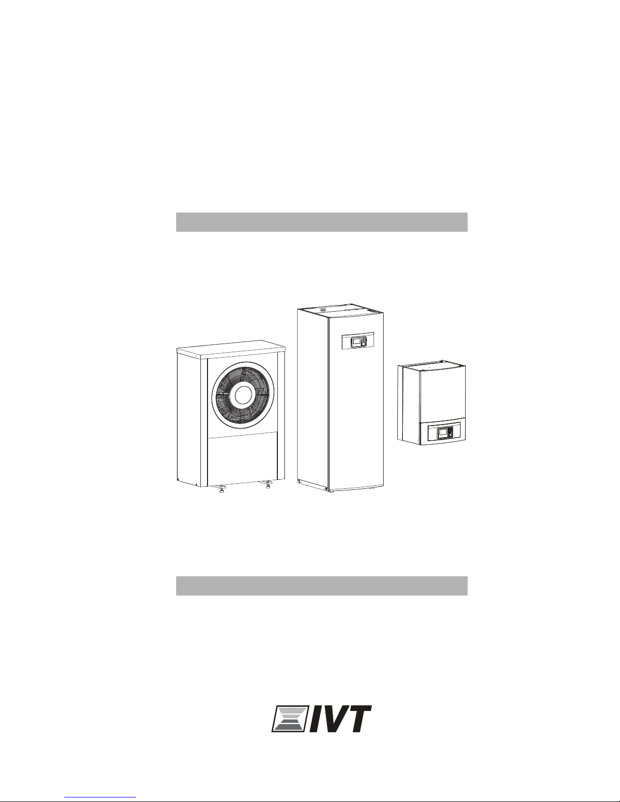
Operating Instructions
AirX, AirModule E 9/15, Airbox E/S
6 720 809 065-00.1I
230V 1N~ / 400V 3N~
6 720 810 266 (2014/10)
Page 2
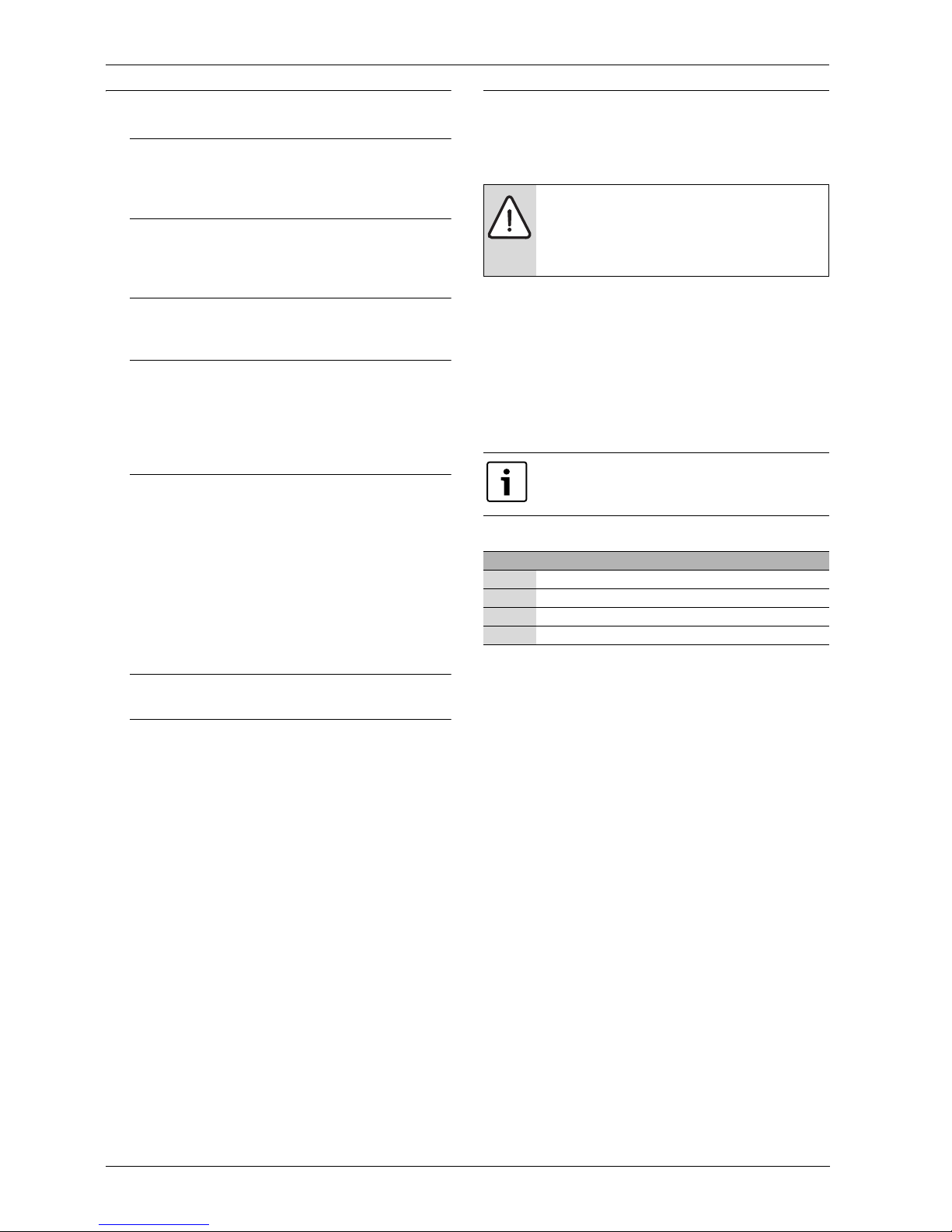
Table of Contents
AirX, AirModule E 9/15, Airbox E/S – 6 720 810 266 (2014/10)
2
Table of Contents
1 Key to symbols and safety instructions . . . . . . . . . . . . . . . . . . . 2
1.1 Key to symbols . . . . . . . . . . . . . . . . . . . . . . . . . . . . . . . . . 2
1.2 General safety instructions . . . . . . . . . . . . . . . . . . . . . . . . 3
2 General . . . . . . . . . . . . . . . . . . . . . . . . . . . . . . . . . . . . . . . . . . . . . . 3
2.1 Control unit . . . . . . . . . . . . . . . . . . . . . . . . . . . . . . . . . . . . 3
2.2 Use . . . . . . . . . . . . . . . . . . . . . . . . . . . . . . . . . . . . . . . . . . . 3
3 System overview . . . . . . . . . . . . . . . . . . . . . . . . . . . . . . . . . . . . . . 4
3.1 Description of the functions . . . . . . . . . . . . . . . . . . . . . . . 4
4 Overview of the most common functions . . . . . . . . . . . . . . . . . 6
4.1 Changing the room temperature . . . . . . . . . . . . . . . . . . . 7
4.2 Setting the operating mode . . . . . . . . . . . . . . . . . . . . . . . 7
4.3 Selecting a heating circuit for the standard display . . . . 8
4.4 Favourite functions . . . . . . . . . . . . . . . . . . . . . . . . . . . . . . 8
5 Maintenance . . . . . . . . . . . . . . . . . . . . . . . . . . . . . . . . . . . . . . . . . 9
5.1 Remove dirt and leaves . . . . . . . . . . . . . . . . . . . . . . . . . . . 9
5.2 Protective covers . . . . . . . . . . . . . . . . . . . . . . . . . . . . . . . 9
5.3 Evaporator . . . . . . . . . . . . . . . . . . . . . . . . . . . . . . . . . . . . . 9
5.4 Snow and ice . . . . . . . . . . . . . . . . . . . . . . . . . . . . . . . . . . . 9
5.5 Moisture . . . . . . . . . . . . . . . . . . . . . . . . . . . . . . . . . . . . . . . 9
5.6 Checking the safety valves . . . . . . . . . . . . . . . . . . . . . . . . 9
5.7 Particle filter . . . . . . . . . . . . . . . . . . . . . . . . . . . . . . . . . . . 9
5.8 Pressure Switch and Overheat protection . . . . . . . . . . 10
5.9 Cleaning the condensate pan . . . . . . . . . . . . . . . . . . . . 12
6 Connection for IP-module . . . . . . . . . . . . . . . . . . . . . . . . . . . . 13
7 Environment / disposal . . . . . . . . . . . . . . . . . . . . . . . . . . . . . . . 13
1 Key to symbols and safety instructions
1.1 Key to symbols
Warnings
The following keywords are defined and can be used in this document:
• NOTICE indicates a situation that could result in damage to property
or equipment.
• CAUTION indicates a situation that could result in minor to medium
injury.
• WARNING indicates a situation that could result in severe injury or
death.
• DANGER indicates a situation that will result in severe injury or death.
Important information
Additional symbols
Warnings in this document are identified by a warning
triangle printed against a grey background.
Keywords at the start of a warning indicate the type and
seriousness of the ensuing risk if measures to prevent
the risk are not taken.
This symbol indicates important information where
there is no risk to people or property.
Symbol Explanation
▶ Step in an action sequence
Cross-reference to another part of the document
• List entry
– List entry (second level)
Table 1
Page 3

General
AirX, AirModule E 9/15, Airbox E/S – 6 720 810 266 (2014/10)
3
1.2 General safety instructions
These operating instructions are intended for the user of the heating
system.
▶ Read any operating instructions (heat pump, heating controls, etc.)
carefully before operation and keep them.
▶ Observe the safety instructions and warnings.
Intended use
This heat pump must only be used as a heat appliance in a sealed hot
water heating system for domestic purposes.
Any other use is considered inappropriate. Any damage that results from
such use is excluded from liability.
Safety of electrical appliances for domestic use and similar
purposes
The following requirements apply in accordance with EN 60335-1 in
order to prevent hazards from occurring when using electrical
appliances:
“This device can be used by children of 8 years and up as well and by
people with reduced physical, sensory or mental capabilities or lacking
in experience and knowledge, if they are supervised and have been given
instruction in the safe use of the device and understand the resulting
dangers. Children must not play with the device. Cleaning and user
maintenance may not be performed by children without supervision”
“If the power supply cable is damaged, in order to avoid risks it must be
replaced by the manufacturer or its customer service department or a
similarly qualified person.”
Inspection and servicing
Regular inspection and maintenance are prerequisites for safe and
environmentally compatible operation of the heating system.
We recommend you enter into a contract for the annual inspection and
demand-dependent servicing with an authorised contractor.
▶ Have any work carried out only by an authorised contractor.
▶ If any faults are discovered, have them remedied immediately.
Modifications and repairs
Unprofessional modifications to the heat pump or other parts of the
heating system can result in injury and/or damage to property or
equipment.
▶ Have any work carried out only by an authorised contractor.
▶ Do not remove the casing of the heat pump.
▶ Do not modify the heat pump or other parts of the heating system in
any way.
Room air
The air in the installation room must be free of combustible or chemically
aggressive substances.
▶ Do not use or store combustible or explosive materials (paper,
propellants, thinners, paints, etc.) within the vicinity of the appliance.
▶ Do not use or store corrosive substances (solvents, adhesives,
chlorinated cleaning agents, etc.) within the vicinity of the appliance.
2 General
Cooling is disabled in the UK model to comply with
the regulations for RHI.
Heat pum p AirX is together with h eat pump module AirModule or Air box
part of a series of heating systems that use outside air to provide energy
for water transferred heat and hot water.
By reversing the process and extract heat from the water and release it
into the outdoor air, the heat pump can if needed produce cooling. This
however requires the heating system to be intended for cooling.
The heat pump outdoors is connected to a heat pump module indoors
and possibly also an external heat source, which constitutes a complete
heating system. The heat pump module with an integrated immersion
heater, or the external source, acts as a supplement when additional
heat is needed, for example if the outside temperature is too low for
effective heat pump operation.
The heating system is operated via a user interface, which is fo und in the
heat pump module. The user interface manages and supervises the
system with different settings for heat, cold, hot water and other
operations. The monitoring function will e.g. turn off the heat pump in
case of disturbances to avoid damage to vital components.
2.1 Control unit
The user interface in the heat pump module manages heat production
based on outside temperature sensors and possibly in combination with
a room controller (accessories). House heating is automatically adjusted
depending on the outside temperature.
The user determines the heating system temperature by setting the
desired room temperature in the user interface or on the room
controller.
A number of accessories can be connected to the heat pump module
(e.g. pool, sun, and room controllers), providing extra functions and
setting possibilities controlled via the user interface. You will find more
information on the accessories in their user guides.
2.2 Use
After the heat pump and the heat pump module have been installed and
taken into operation, some regular maintenance is required. This might
include checking on an alarm, or other simple maintenance. The user is
usually able to solve the problem, however if it remains, the retailer
should be contacted.
Page 4
System overview
AirX, AirModule E 9/15, Airbox E/S – 6 720 810 266 (2014/10)
4
3 System overview
The heating system consists of two parts: the heat pump, which is
installed outdoors, and the heat pump module with or without integrated
hot water cylinder, which is installed indoors (AirModule and Airbox E).
Installation may be done using an external heat source, and the
supplemental heat source will then consist of an existing electric/gas/oil
boiler (Airbox S).
The most common heating systems are consistent with one of these
alternatives, however the system flexibility makes other combinations
possible.
3.1 Description of the functions
In a house with water based heating a difference is made between
heating water and domestic hot water (DHW). The heating water is for
radiators and floor coils and hot water is for showers and taps.
If there is a DHW cylinder in the system, the user interface will make sure
the heating of DHW is prioritised before heating of heating water for
optimised comfort.
3.1.1 Heat pump (outdoor unit)
The task of the heat pump is to retrieve energy from the outside air and
transfer it to the heat pump module.
The heat pump is inverter operated, which means that it will
automatically change the compressor speed to deliver the exact amount
of energy required at the moment. The fan is also RPM controlled and will
change its speed as needed. This provides the lowest possible energy
consumption.
Defrosting
Ice might form on the evaporator during lower outside temperatures. In
case there is enough ice to inhibit the air flow through the evaporator, an
automatic defrosting will start. As soon as the ice is gone, the heat pump
returns to its normal operation.
If the outside temperature is above +5°C the defrosting will be
performed alongside continued heat production, however if the
temperature is lower, the defrosting is done by ways of a 4-way valve
turning the heat medium direction in the circuit so that the hot gas from
the compressor melts away the ice.
Function principle
The heat production principle:
• The fan sucks up air through the evaporator.
• The energy in the air makes the refrigerant boil. The resulting gas is
drawn into the compressor.
• In the compressor, the pressure of the refrigerant is increased, and
the temperature rises. The hot gas is pushed into the condenser.
• In the condenser, the energy is transferred from the gas to water in the
heat transfer circuit. The gas is cooled down and turns into liquid.
• The pressure on the refrigerant is decreased and transferred back to
the evaporator. When the refrigerant passes the evaporator, it turns
back into gas.
• In the heat pump module, the energy is transferred from the heat
transfer circuit to the house heating system and hot water cylinder.
3.1.2 Heat pump module (indoor unit)
The heat pump module task is to distribute t he heat from the heat pump
to the heating system and the hot water cylinder. The circulation pump
in the heat pump module is RPM controlled, and will automatically
decrease in speed when demand is low. This decreases energy
consumption.
When the heating demand is higher during cold outdoor temperatures,
an additional heat source - a booster - may be required. This booster
heater is either integrated or external, an its on/off is controlled by the
user interface in the heat pump module. Please note that when the heat
pump is running, the booster heater will only provide the heating output
that the heat pump cannot produce itself. When the he at pu mp is able t o
provide all the heating needed, the booster is automatically turned off.
The heat pump stops around – 20 °C; heating and DHW
production is then taken over by the heat pump module
or a external heat source.
Page 5
System overview
AirX, AirModule E 9/15, Airbox E/S – 6 720 810 266 (2014/10)
5
AirModule
Heat pump AirX connected to heat pump module AirModule provides a
complete installation for both heating and domestic hot water, since the
heat pump module contains a hot water cylinder. Switching between
heating and DHW is managed by an internal 3-way valve. The integrated
booster in the heat pump module will turn on if needed.
Fig. 1 Heat pump AirX, heat pump module AirModule with integrated hot water cylinder and immersion heater
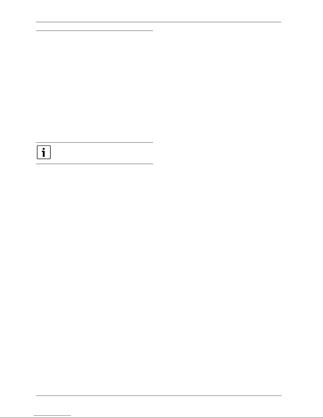
Airbox E
When heat pump AirX is connected to heat pump module AirBox E, an
external hot water cylinder is required if the purpose of the heat pump is
also to produce hot water. In this case, switching between heating and
DHW is managed by an external 3-way valve. The integrated booster in
the heat pump module will turn on if needed.
Fig. 2 Heat pump AirX, heat pump module Airbox with immersion heater, external hot water cylinder
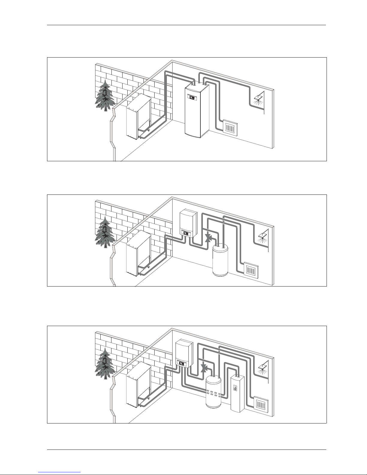
Airbox S
When heat pump AirX is connected to heat pump module AirBox S, an
external hot water cylinder is required if the purpose of the heat pump is
also to produce hot water. In this case, switching between heating and
DHW is managed by an external 3-way valve. The module contains a
mixing valve that regulates the heat from the external booster, which is
turned on when needed.
Fig. 3 Heat pump AirX, heat pump module Airbox without immersion heater, external hot water cylinder and external booster
Page 6

Overview of the most common functions
AirX, AirModule E 9/15, Airbox E/S – 6 720 810 266 (2014/10)
6
4 Overview of the most common functions
Fig. 4 Keys
In the user interface operating instructions you will find a
complete description of all functions and settings.
Pos. Key Designation Explanation
1 Favourites key ▶ Press this key to show favourite functions for heating circuit 1.
▶ Keep this key pressed down to change Favourites menu settings.
2 Extra DHW key ▶ Press this key to activate the extra DHW function.
3 DHW key ▶ Press this key to select DHW mode.
4 Menu key ▶ Press this key to enter the mai n menu.
5 Info key When a menu is shown:
▶ Press this key for more information about the selected menu option.
When standard display is active:
▶ Press this key to enter the information menu.
6 Return key ▶ Press this key to return to the previous menu or to cancel changes.
For maintenance or when an error has been detected:
▶ Press this key to switch between standard display and error message.
▶ Keep this key pressed down to switch between a menu and the standard display.
7 Selector ▶ Turn the selector to change a set value (e.g. the temperature) or to select a menu or menu option.
When the display is off:
▶ Press the selector to turn on the display.
When the display is on:
▶ Press the selector to open a selected menu or menu option, o r confirm a set value (e.g. temperature) or a message, or
to close a pop-up window.
When standard display is active:
▶ Press the selector to a ctivate the input window for heating circuit options in the standard display (only valid for
installations with at least two heating circuits).
Table 2 Keys
menu
fav
info
6 720 808 471-01.1O
5
6
7
4
2
3
1
fav
menu
info
Page 7

Overview of the most common functions
AirX, AirModule E 9/15, Airbox E/S – 6 720 810 266 (2014/10)
7
4.1 Changing the room temperature
4.2 Setting the operating mode
Optimised operation is active with the standard settings, since this operating mode ensures the most effective heat pump operation.
Operation Results
If some day you are cold or feel it is too hot: temporarily change the room temperature
Automatic mode
Change the room temperature until the next switching time
▶ Turn the selector to set desired room temperature.
The corresponding time slot is displayed in grey in the time program bar chart.
▶ Wait a few seconds or press the selector.
The user interface operates with the modified setting. The change applies until the next switching time in your heating time
program is reached. After this, the time program settings are restored.
Undoing a temperature change
▶ Turn the select or until the corresponding time slot tu rns back to bl ack in the ti me program bar chart and press the selector.
The change is undone.
If you are always cold or feel it is too hot: set desired room temperature (e.g. for heating and setback operating mode)
Optimised operation
▶ Activate optimized operation ( chapter 4.2).
▶ Wait a few seconds or press the selector to close the pop-up window.
▶ Turn the selector to set desired room temperature.
▶ Wait a few seconds or press the selector. Confirm the change in the pop-up window by pressing the selector (or undo the
change by pressing the Return key).
Current room temperature is shown in a pop-up window in the lower part of the display.
The user interface operates with the modified settings.
Automatic mode
▶ Press the menu k ey to enter the main menu.
▶ Press th e selector to open the Heating/Cooling menu.
▶ Turn the selec tor to highlight the Temperature settings menu.
▶ Press th e selector to open the menu.
▶ If two or more heating circuits are installed: turn the selector to highlight Heating circuit 1, 2, 3 or 4 and press the
selector.
▶ Turn the selector to h ighlight Heating or Setback.
▶ Press the selector.
▶ Turn the selector to h ighlight desired setback operation setting.
▶ Press the selector t o activate selected setting.
When temperature control is activated:
▶ turn the selector and press it to set the temperature. The temperature setting value limits are determined by the settings
for the other operating mode.
The user interface operates with the modified settings. The settings apply to all heating time programs (when two or more
heating circuits are set it only applies to the selected heating circuit).
Table 3 Room temperature
Operation Results
If you want to activate optimised operation (without time program)
▶ Press the m enu key to enter the main menu.
▶ Press the select or to open the Heating/Cooling menu.
▶ Press the select or to open the Operating mode menu.
▶ If two or more heating circuits are installed: turn the selector to highlight Heating circuit 1, 2, 3 or 4 and press the selector.
▶ Turn the selector to highlight Optimised and press the selector.
▶ Return to the standard display by pressing the Return key and keeping it pressed down.
Desired room temperature is shown in the lower part of the display, in a pop-up window. The user interface will change the
permanent room temperature to the desired room temperature.
If you want to activate automatic mode (and use the time program)
▶ Press the m enu key to enter the main menu.
▶ Press the select or to open the Heating/Cooling menu.
▶ Press the select or to open the Operating mode menu.
▶ If two or more heating circuits are installed: turn the selector to highlight Heating circuit 1, 2, 3 or 4 and press the selector.
▶ Turn the selector to highlight Auto and press the selector.
▶ Return to the standard display by pressing the Return key and keeping it pressed down.
All temperatures set in the current time program for heating are shown in the lower part of the display, in a pop-up window.
Current temperature flashes.The user interface regulates the room temperature according to the active heating time program.
Table 4 Getting started – Activating operating modes
6 720 811 136-05.1O
6 720 811 136-06.1O
6 720 811 136-07.1O
6 720 811 136-08.1O
6 720 811 136-04.1O
6 720 811 136-05.1O
Page 8

Overview of the most common functions
AirX, AirModule E 9/15, Airbox E/S – 6 720 810 266 (2014/10)
8
4.3 Selecting a heating circuit for the standard display
The standard display only ever shows data for a single heating circuit. If
two or more heating circuits are installed, a setting can be made to
determine which heating circuit the data in the standard display relates
to.
4.4 Favourite functions
The Favourites key provides direct access to the functions that you use
most often with heating circuit 1. When you press the Favourites key for
the first time, the menu Configuration of the Favourites menu appears.
Here, you are able to save your personal favourites and modify the
Favourites menu according to your needs on a later occasion.
The Favourites key function depends on the heating circuit shown in the
standard display. The settings that are modified in the Favourites menu
only apply to heating circuit 1.
Operation Results
▶ If the display is on, press the selector.
Current selected heating circuit number, operating mode and name (optional) is shown in the lower part of the display.
▶ Turn the selector to select a heating circuit.
Only heating circuits that exist in the system are displayed for selection.
▶ Wait a few seconds or press the selector.
The standard display displays the selected heating circuit.
Table 5 General – Heating circuit in standard display
6 720 811 136-02.1O
Operation Results
When you want to use a Favourites function: open the Favourites menu
▶ Press the F avourites key to open the Favourites menu.
▶ Turn the selector and press to select a favourite function.
▶ Modify settings (this is done in the same way as in the main menu).
If you want to modify the favourite functions list according to your own needs: Modify Favourites menu
▶ Press the Favourites key and keep it pressed down until the menu Configuration of the Favourites menu is shown.
▶ Turn and press the selector to select a function (Yes) or to cancel your selection (No).
The changes are effective immediately.
▶ Press the Return key t o close the menu.
Table 6 Favourite functions
6 720 811 136-15.1O
Page 9

Maintenance
AirX, AirModule E 9/15, Airbox E/S – 6 720 810 266 (2014/10)
9
5 Maintenance
The heat pump requires a minimum of maintenance, however, some
servicing is still required to get optimal performance from your heat
pump. Check the following items a few times per year:
• Remove dirt and leaves
•Cover
• Evaporator
5.1 Remove dirt and leaves
▶ Use a brush to remove the dirt and leaves from the heat pump.
5.2 Protective covers
Over time dust and other dirt will collect on the heat pump.
▶ If required, wipe the cover with a damp cloth.
▶ Scratches and damage to the outer cover should be treated with rust
protection.
▶ The lacquer can be protected with car wax.
5.3 Evaporator
If a film has formed (e.g. dust or dirt) on the evaporator surface, it must
be removed.
To clean the evaporator:
▶ Spray the evaporator fins with the cleaning product on the back of the
heat pump.
▶ Rinse off dirt and the cleaning product with water.
5.4 Snow and ice
In some geographical regions or during periods of heavy snow, snow can
get stuck on the back of the heat pump.
▶ Carefully brush the snow off the fins.
5.5 Moisture
Moisture might develop under the heat pump (outdoors) due to
condensation not collected by the condensate pan. This is normal and
does not require any action.
5.6 Checking the safety valves
▶ Check the DHW safety valve by pressing the valve lever.
▶ Check that the safety valve leakage drain hose is not plugged.
5.7 Particle filter
Check the heating system and collector system particle filters
The filters will prevent dirt from entering the heat pump. Operating
problems might occur if these are blocked.
Cleaning the strainer
▶ Close the valve (1).
▶ Screw off the hood (by hand), (2).
▶ Take out the strainer and clean it by running water over it.
▶ Put the strainer back; it has rails that fit into the groove in the valve to
avoid incorrect installation (3).
Fig. 5 Filter version without circlip
▶ Screw back the hood (by hand).
▶ Open the valve (4).
DANGER: The heat pump is connected to high current.
▶ Break the power supply before rectifying.
Using the wrong cleaning product may damage the
installation!
▶ Do not use acid or chlorine based products since they
contain abrasives.
WARNING: The thin aluminium fins are fragile and can
be damaged if careless. Never wipe the delicate fins with
a cloth.
▶ Use protective gloves to protect your hands from
cuts.
▶ Do not use a too powerful water jet.
NOTICE: If you often find moisture near the heat pump
module or the fan convector, this might indicate gaps in
the condensation insulation.
▶ Turn off the heat pump and contact your retailer of
you find moisture surrounding one of the heat system
components.
The safety valve should be checked by a qualified
engineer - usually as part of an annual service visit.
Water is expelled from the safety valve during heat-up.
Never close the safety valve.
It is not necessary to empty the installation in order to
clean the filters. Filter and shut-off valve are integrated.
1.
2.
2.
1.
1
2
3
4
6 720 805 915-01.1I
Page 10

Maintenance
AirX, AirModule E 9/15, Airbox E/S – 6 720 810 266 (2014/10)
10
5.8 Pressure Switch and Overheat protection
If the pressure switch has tripped resets itself when the pressure is
sufficient in the system.
▶ Check the pressure gauge.
▶ If the pressure is below 0.5 bar, slowly increase the pressure in the
heating system by adding water to the filling valve to a maximum of 2
bar.
▶ Contact the installer or retailer if you are unsure of how to proceed.
To reset the overheat protection on AirModule:
▶ Pull out the front cover by the bottom and lift it off upwards.
▶ Press the button hard on the overheating protection.
▶ Put the front cover back.
To reset the overheat protection on AirBox E:
▶ Contact the installer or retailer
Fig. 6 AirBox E
[1] Pressure gauge
Pressure switch and overheat protection are only in heat
pump module with integrated electrical supplement.
Overheat protection must be manually reset if it trips.
The pressure switch and overheat protection are
connected in series, triggered alarm or information in
the controll unit means either low pressure in the system
or to high temperature in the additional heater.
1 6 720 810 156-11.1I
Page 11

Maintenance
AirX, AirModule E 9/15, Airbox E/S – 6 720 810 266 (2014/10)
11
Fig. 7 AirModule
[1] Reset overheating protection
[2] Particle filter
[3] Pressure gauge
1
6 720 810 156-10.1I
3
2
Page 12

Maintenance
AirX, AirModule E 9/15, Airbox E/S – 6 720 810 266 (2014/10)
12
5.9 Cleaning the condensate pan
If the user interface shows an alarm indicating that the heat pump cover
requires cleaning, the condensate pan should be cleared of dirt and
leaves, which inhibit defrosting.
▶ Screw off the protective cover.
▶ Clean the condensate pan with a cloth or soft brush.
▶ Put the protective cover back.
Fig. 8 Heat pump condensate pan
[1] Condensate pan
Warning: The thin aluminum fins of the evaporator are
sharp and delicate and can be damaged by negligence.
▶ Wear gloves to protect hands from cuts
▶ Be careful not to damage the fins
6 720 809 065-11.1I
1
Page 13

Connection for IP-module
AirX, AirModule E 9/15, Airbox E/S – 6 720 810 266 (2014/10)
13
6 Connection for IP-module
The heat pump module AirModule has a built in IP-module, which is
available as an accessory to the AirBox. The IP-module may be used to
manage and monitor the heat pump module and the heat pump from a
mobile unit. It is used as an interface between the heating system and a
network (LAN) and enables the SmartGrid function.
Commissioning
The router must be configured as follows:
• DHCP enabled
• Ports 5222 and 5223 may not be blocked from outgoing traffic.
• Free IP address available
• The address filter (MAC filter) must not filter out the module.
During commissioning of the IP-module, the following is possible:
• Internet
The module automatically obtains an IP address from the router. The
name and address of the target server are stored in the standard
settings of the module. As soon as an internet connection is
established, the module automatically logs on to the server.
• Local network
The module must not be connected to the internet. It can also be used
in a local network. In this case, however, the module cannot be
reached via the internet, and the module software cannot
automatically update.
• The app IVT AnyWare
When the app is opened for the first time, the predefined login name
and password must be entered. The login information can be found on
the IP-module data plate.
•SmartGrid
The heat pump module can communicate with the electricity market
and will in this case adjust operation so that the heat pump operates
at its maximum when the cost of electricity is lower. See the website
for further information.
Login data for IP-module
Manufact.no.:__ __ __ __ - __ __ __ __ __ __ __ __ __ - __ __ __ __ __ __ __ __ __ __
Login name: ___ ___ ___ ___ ___ ___ ___ ___ ___
Password: __ __ __ __ - __ __ __ __ - __ __ __ __ - __ __ __ __
Mac: ___ ___ - ___ ___ - ___ ___ - ___ ___ - ___ ___ - ___ ___
7 Environment / disposal
Environmental protection is a fundamental corporate strategy of the
Bosch Group.
The quality of our products, their economy and environmental safety are
all of equal importance to us and all environmental protection legislation
and regulations are strictly observed.
We use the best possible technology and materials for protecting the
environment taking account of economic considerations.
Packaging
We participate in the recycling programmes of the countries in which our
products are sold to ensure optimum recycling.
All of our packaging materials are environmentally compatible and can
be recycled.
Used appliances
Used appliances contain valuable materials that should be recycled.
The various assemblies can be easily dismantled and synthetic materials
are marked accordingly. Assemblies can therefore be sorted by
composition and passed on for recycling or disposal.
Use of all the functions requires an internet connection
and a router with an available RJ45 output. This may
incur additional costs. Managing the installation from a
cell phone requires the free app IVT Anywhere.
Please refer to the router documentation during
commissioning.
NOTICE: You will lose your login information when you
change IP-module!
Each IP-module has its own unique login information.
▶ Enter your login information after commissioning in
the appropriate field.
▶ Change the information according to the new IP-
module if it has been changed.
You can also change the password in the
user interface.
Page 14

Technical glossary
AirX, AirModule E 9/15, Airbox E/S – 6 720 810 266 (2014/10)
14
Technical glossary
Heat pump
The central heat source. Placed outdoors, also referred to as an outside
unit. Contains the cooling circuit. Waterborne heating or cooling is
transferred from the heat pump to the heat pump module.
Heat pump module
Placed indoors and distributes the heat from the heat pump to the
heating system or the water heater. Contains the user interface and the
circulation pump for the water to the heat pump.
Heating installation
Includes the entire installation, with heat pump, heat pump module,
water heater, heating system and accessories.
Heating system
Comprises the heat source, cylinders, radiators, underfloor heating
system or fan convector or a combination of these if the heating system
has several heating circuits.
Heating circuit
The part of the heating system that distributes heat to different rooms.
Consists of pipework, circulation pump and either radiators, underfloor
heating system loops or fan convectors. Only one of these alternatives is
possible in one circuit, but if there are e.g. two circuits in the heating
system, then one may comprise radiators and the other underfloor
heating system loops. A heating circuit can be installed with or without a
mixing valve.
Heating circuit without mixing valve
A heating circuit without mixing valve does not contain a mixer; the
temperature on the circuit is maintained completely b y th e he at f rom th e
heat source.
Heating circuit with mixing valve
A heating circuit with mixing valve contains a mixer, which mixes in the
closed circuit water with the water from the heat pump. This means that
the heating circuit with mixing valve can maintain a lower temperature
than the rest of the heating system, which may be used to separate
underfloor heating system loops that use a lower temperature from
radiators that operate at a higher temperature.
Mixing valve
The mixing valve is a valve that seamlessly mixes cooler closed circuit
water with water from the heat source to reach the desired temperature.
The mixing valve may be placed in a heating circuit or in a heat pump
module as an external booster mixer.
3-way valve
The 3-way valve distributes heat either to the heating circuits or to the
water heater. The valve has two fixed modes, hence the heating and
DHW production cannot occur simultaneously. This provides for the
most effective operation, since DHW is always heated to a specific
temperature, while the heating water temperature is adjusted
continuously according to current outdoor temperature.
External booster heater
The external booster is a separate heat source, which is connected to the
heat pump module with pipework. The heating from the booster is
regulated via a mixing valve, and is therefore also called a mixing valve
booster. The user interface manages the booster on/off based on the
current heating requirements. The heat source is either an electric, oil or
gas boiler.
Heat transfer circuit
The part of the heating system that transfers heat from the heat pump to
the heat pump module.
Cooling circuit
Cooling is disabled in the UK model to comply with
the regulations for RHI.
The main part of the heat pump, which retrieve energy from outside air
and transfers it as heat to the heat transfer circuit. Consists of
evaporator, compressor, condenser and expansion valve. The
refrigerant circulates in the cooling circuit.
Evaporator
A heat exchanger between air and refrigerant. The energy in the air,
which is sucked up through the evaporator makes the refrigerant boil
and turn into gas.
Compressor
Makes the refrigerant circulate in the coolant circuit, from the
evaporator to the condenser and back. Increases the gaseous
refrigerant pressure. When the pressure increases, the temperature
increases too.
Condenser
Is a heat exchanger between the refrigerant in the cooling circuit and the
water in the heat transfer circuit. When heat is transferred, the
refrigerant temperature decreases as it is condensed into a liquid.
Expansion valve
Decreases the refrigerant pressure when it comes from the condenser.
The refrigerant is then transferred back to the evaporator, where the
process starts over.
Inverter
Is found in the heat pump and enables RPM control of the compressor
according to current heating requirements.
Setback phase
A time slot during automatic mode, with Setback operating mode.
Automatic mode
The heating system is heating in accordance with the time program and
an automatic changeover takes place between operating modes.
Operating mode
The operating modes for heating are: Heating and Setback. These are
indicated by the symbols and .
The operating modes for water heating are: DHW, DHW reduced and
Off.
It is possible to set a temperature for each operating mode (except Off).
Frost protection
Depending on the selected frost protection, the heat pump will turn on
when the outside and/or room temperature reaches below a certain set
threshold. Frost protection prevents the heating system from freezing
up.
Required room temperature (also desired or set temperature/set
room temp.)
The room temperature to be achieved by the heating system. It can be
set individually.
Default setting
Values permanently saved in the programming unit (e.g. complete time
programs) that are available at any time and that can be reinstated
according to demand.
Heating phase
A time slot during automatic mode, with Heating operating mode.
Page 15

Technical glossary
AirX, AirModule E 9/15, Airbox E/S – 6 720 810 266 (2014/10)
15
Child lock
The standard display settings and in the menu can only be modified if the
child lock (key lock) has been disabled ( page 8).
Mixing device
Assembly that automatically ensures that hot water can be drawn from
the taps at a temperature no higher than the temperature set on the
mixer.
Optimised operation
Automatic mode (the heating time program) is not active during
optimized operation, instead the system is continuously heating
according to the temperature set for optimized operation.
Reference room
The reference room is the room in the home where a room unit has been
installed. The room temperature in this room acts as the control variable
for the assigned heating circuit.
Switching time
A certain time at which the heating system starts to heat or hot water is
produced, for example. A switching time is a component of a time
program.
Temperature of an operating mode
A temperature that is assigned to an operating mode. The temperature is
adjustable. See the explanations on operating mode.
Flow temperature
Temperature at which the heated water flows in the central heating
system from the heat source to the heating surfaces in the rooms.
Hot water cylinder
A hot water cylinder stores large volumes of heated tap DHW. Thereby,
sufficient DHW is available at the draw-off points (e.g. taps). This is a
prerequisite for longer hot showers.
Time program for the heating system
This time program ensures automatic changeover between operating
modes at defined switching times.
Page 16

Alto Energy Limited
Unit 17 Glenmore Business Centre
Witney, Oxfordshire OX29 0AA
United Kingdom
www.altoenergy.co.uk | support@altoenergy.co.uk
 Loading...