

IVT AirModule E 15, AirModule E 9, Airbox E 50- 90, Airbox E 130-170, Airbox S 50- 90 Installer's Manual
...Page 1

AirModule E 9/15
230V 1N~ / 400V 3N~
Installer Guide
6 720 813 268(2014/10)
6 720 809 156-00.1I
Page 2

Table of Contents
Table of Contents
1 Key to symbols and safety instructions . . . . . . . . . . . . . . . . . . . . . . . . . 3
1.1 Key to symbols . . . . . . . . . . . . . . . . . . . . . . . . . . . . . . . . . . . . . . . 3
1.2 General safety instructions . . . . . . . . . . . . . . . . . . . . . . . . . . . . . 3
8.12 Connection option EMS bus . . . . . . . . . . . . . . . . . . . . . . . . . . . 33
9 User interface . . . . . . . . . . . . . . . . . . . . . . . . . . . . . . . . . . . . . . . . . . . . . 34
9.1 Product description . . . . . . . . . . . . . . . . . . . . . . . . . . . . . . . . . . 34
9.2 Important notices on usage . . . . . . . . . . . . . . . . . . . . . . . . . . . . 34
9.3 Optional accessories . . . . . . . . . . . . . . . . . . . . . . . . . . . . . . . . . 34
2 Standard delivery . . . . . . . . . . . . . . . . . . . . . . . . . . . . . . . . . . . . . . . . . . . 4
3 General . . . . . . . . . . . . . . . . . . . . . . . . . . . . . . . . . . . . . . . . . . . . . . . . . . . . 4
3.1 Information about the heat pump . . . . . . . . . . . . . . . . . . . . . . . . 4
3.2 Application area . . . . . . . . . . . . . . . . . . . . . . . . . . . . . . . . . . . . . . 4
3.3 Heating system minimum volume and operation . . . . . . . . . . . . 4
3.4 Type plate . . . . . . . . . . . . . . . . . . . . . . . . . . . . . . . . . . . . . . . . . . . 5
3.5 Transport and storage . . . . . . . . . . . . . . . . . . . . . . . . . . . . . . . . . 5
3.6 Heat pump module positioning . . . . . . . . . . . . . . . . . . . . . . . . . . 5
3.7 Checks before installation . . . . . . . . . . . . . . . . . . . . . . . . . . . . . . 5
3.8 Connection principle . . . . . . . . . . . . . . . . . . . . . . . . . . . . . . . . . . 5
4 Technical information . . . . . . . . . . . . . . . . . . . . . . . . . . . . . . . . . . . . . . . . 6
4.1 Technical information - heat pump module . . . . . . . . . . . . . . . . 6
4.2 System configurations . . . . . . . . . . . . . . . . . . . . . . . . . . . . . . . . . 7
5 Measurements, positioning distance, and pipe connections . . . . . . 11
5.1 Heat pump module dimensions and connections . . . . . . . . . . 11
5.2 Pipework . . . . . . . . . . . . . . . . . . . . . . . . . . . . . . . . . . . . . . . . . . . 13
6 Regulations . . . . . . . . . . . . . . . . . . . . . . . . . . . . . . . . . . . . . . . . . . . . . . . . 13
7 Installation . . . . . . . . . . . . . . . . . . . . . . . . . . . . . . . . . . . . . . . . . . . . . . . . 14
7.1 Detailed discharge pipe installation requirements (Combi model)
. . . . . . . . . . . . . . . . . . . . . . . . . . . . . . . . . . . . . . . . . . . . . . . . . . 14
7.2 Preparatory pipework . . . . . . . . . . . . . . . . . . . . . . . . . . . . . . . . 14
7.3 Positioning . . . . . . . . . . . . . . . . . . . . . . . . . . . . . . . . . . . . . . . . . 14
7.4 Checklist . . . . . . . . . . . . . . . . . . . . . . . . . . . . . . . . . . . . . . . . . . . 14
7.5 Water quality . . . . . . . . . . . . . . . . . . . . . . . . . . . . . . . . . . . . . . . 15
7.6 Heating system flushing . . . . . . . . . . . . . . . . . . . . . . . . . . . . . . . 15
7.7 Operation without heat pump (stand-alone) . . . . . . . . . . . . . . 15
7.8 Installation with cooling . . . . . . . . . . . . . . . . . . . . . . . . . . . . . . . 15
7.9 Installation with solar heater (only solar model) . . . . . . . . . . . 16
7.10 Installation with pool . . . . . . . . . . . . . . . . . . . . . . . . . . . . . . . . . 16
7.11 Connecting the heat pump module to the heat pump . . . . . . . 17
7.12 Connecting the heat pump module to the heating system and tap
water . . . . . . . . . . . . . . . . . . . . . . . . . . . . . . . . . . . . . . . . . . . . . 18
7.13 Low energy pump for heat transfer medium (PC0) . . . . . . . . . 19
7.14 Circulation pump for the heating system (PC1) . . . . . . . . . . . . 19
7.15 DHW circulation pump PW2 (accessory) . . . . . . . . . . . . . . . . . 19
7.16 Insulation . . . . . . . . . . . . . . . . . . . . . . . . . . . . . . . . . . . . . . . . . . 19
7.17 Several heating circuits (mixing valve module accessory, see
separate instructions) . . . . . . . . . . . . . . . . . . . . . . . . . . . . . . . . 19
7.18 Installation of condensation sensor (accessories) . . . . . . . . . . 19
7.19 Temperature sensor installation . . . . . . . . . . . . . . . . . . . . . . . . 20
7.20 Heat pump and heat pump module filling . . . . . . . . . . . . . . . . . 22
10 Basic principles of operation . . . . . . . . . . . . . . . . . . . . . . . . . . . . . . . . . 35
10.1 Key and symbol overview . . . . . . . . . . . . . . . . . . . . . . . . . . . . . 35
10.2 Display symbols overview . . . . . . . . . . . . . . . . . . . . . . . . . . . . . 36
10.3 Using the service menu . . . . . . . . . . . . . . . . . . . . . . . . . . . . . . . 37
10.4 Service menu overview . . . . . . . . . . . . . . . . . . . . . . . . . . . . . . . 38
11 Commissioning . . . . . . . . . . . . . . . . . . . . . . . . . . . . . . . . . . . . . . . . . . . . 38
11.1 General user interface commissioning . . . . . . . . . . . . . . . . . . . 38
11.2 System commissioning via configuration wizard . . . . . . . . . . . 39
11.3 Commissioning other settings . . . . . . . . . . . . . . . . . . . . . . . . . 40
11.4 Performing the function test . . . . . . . . . . . . . . . . . . . . . . . . . . . 40
11.5 Check monitored values . . . . . . . . . . . . . . . . . . . . . . . . . . . . . . 40
11.6 System handover . . . . . . . . . . . . . . . . . . . . . . . . . . . . . . . . . . . . 40
12 Service menu . . . . . . . . . . . . . . . . . . . . . . . . . . . . . . . . . . . . . . . . . . . . . . 41
12.1 Heat pump settings . . . . . . . . . . . . . . . . . . . . . . . . . . . . . . . . . . 42
12.2 Booster heater settings . . . . . . . . . . . . . . . . . . . . . . . . . . . . . . . 43
12.3 Settings for heating/cooling . . . . . . . . . . . . . . . . . . . . . . . . . . . 44
12.4 DHW settings . . . . . . . . . . . . . . . . . . . . . . . . . . . . . . . . . . . . . . . 52
12.5 Pool settings . . . . . . . . . . . . . . . . . . . . . . . . . . . . . . . . . . . . . . . 53
12.6 Solar system settings . . . . . . . . . . . . . . . . . . . . . . . . . . . . . . . . 53
12.7 Hybrid system settings . . . . . . . . . . . . . . . . . . . . . . . . . . . . . . . 53
12.8 Anti-seizing protection settings . . . . . . . . . . . . . . . . . . . . . . . . 53
12.9 Diagnostics menu . . . . . . . . . . . . . . . . . . . . . . . . . . . . . . . . . . . 54
13 Troubleshooting . . . . . . . . . . . . . . . . . . . . . . . . . . . . . . . . . . . . . . . . . . . 55
14 Heat pump and heat pump module venting . . . . . . . . . . . . . . . . . . . . . 57
15 Heat pump module components replacement . . . . . . . . . . . . . . . . . . 58
16 Function check . . . . . . . . . . . . . . . . . . . . . . . . . . . . . . . . . . . . . . . . . . . . . 58
16.1 Set heating system operating pressure . . . . . . . . . . . . . . . . . . 58
16.2 Pressure switch and overheating protection . . . . . . . . . . . . . . 58
16.3 Operating temperatures . . . . . . . . . . . . . . . . . . . . . . . . . . . . . . 58
17 Environmental protection . . . . . . . . . . . . . . . . . . . . . . . . . . . . . . . . . . . 59
18 Maintenance . . . . . . . . . . . . . . . . . . . . . . . . . . . . . . . . . . . . . . . . . . . . . . . 59
19 Connection for IP module . . . . . . . . . . . . . . . . . . . . . . . . . . . . . . . . . . . . 61
20 Commissioning protocol . . . . . . . . . . . . . . . . . . . . . . . . . . . . . . . . . . . . 62
8 Electric installation . . . . . . . . . . . . . . . . . . . . . . . . . . . . . . . . . . . . . . . . . 23
8.1 CAN-BUS . . . . . . . . . . . . . . . . . . . . . . . . . . . . . . . . . . . . . . . . . . 23
8.2 EMS-BUS . . . . . . . . . . . . . . . . . . . . . . . . . . . . . . . . . . . . . . . . . . 23
8.3 Printed circuit board handling . . . . . . . . . . . . . . . . . . . . . . . . . . 24
8.4 External connections . . . . . . . . . . . . . . . . . . . . . . . . . . . . . . . . . 24
8.5 Accessories . . . . . . . . . . . . . . . . . . . . . . . . . . . . . . . . . . . . . . . . 24
8.6 Connecting the heat pump module . . . . . . . . . . . . . . . . . . . . . . 24
8.7 Electric box layout . . . . . . . . . . . . . . . . . . . . . . . . . . . . . . . . . . . 25
8.8 Power supply heat pump and heat pump module 9 kW 3N~ . 29
8.9 Power supply heat pump and heat pump module 15 kW . . . . 30
8.10 Installer module circuit diagram . . . . . . . . . . . . . . . . . . . . . . . . 31
8.11 Heat pump/heat pump module circuit diagram . . . . . . . . . . . . 32
2
AirModule 6 720 813 268(2014/10)
Page 3

Key to symbols and safety instructions
1 Key to symbols and safety instructions
1.1 Key to symbols
Warnings
Warnings in this document are identified by a warning
triangle printed against a grey background.
Keywords at the start of a warning indicate the type and
seriousness of the ensuing risk if measures to prevent
the risk are not taken.
The following keywords are defined and can be used in this document:
• NOTICE indicates a situation that could result in damage to property
or equipment.
• CAUTION indicates a situation that could result in minor to medium
injury.
• WARNING indicates a situation that could result in severe injury or
death.
• DANGER indicates a situation that will result in severe injury or
death.
Important information
This symbol indicates important information where
there is no risk to people or property.
Additional symbols
Symbol Explanation
▶ Step in an action sequence
Cross-reference to another part of the document
• List entry
– List entry (second level)
Table 1
1.2 General safety instructions
These installation instructions are intended for plumbers, heating
engineers and electricians.
▶ Read any installation instructions (heat pump, heating controls, etc.)
carefully before starting the installation.
▶ Observe the safety instructions and warnings.
▶ Observe national and regional regulations, technical rules and
guidelines.
▶ Record all work carried out.
Intended use
This heat pump must only be used as a heat appliance in a sealed hot
water heating system for domestic purposes.
Any other use is considered inappropriate. Any damage that results from
such use is excluded from liability.
Installation, commissioning and servicing
Installation, commissioning and servicing must only be carried out by an
authorised contractor.
▶ Only use original spares.
Electrical work
Electrical work must only be carried out by a qualified electrician.
▶ Before starting electrical work:
– Isolate the mains electrical supply and secure against
unintentional reconnection.
– Check for zero potential.
▶ Also observe connection diagrams of other system components.
Handover to the user
When handing over, instruct the user how to operate the heating system
and inform him about its operating conditions.
▶ Explain how to operate the heating system and draw the user's
attention to any safety-relevant action.
▶ Explain that modifications and repairs must only be carried out by an
authorised contractor.
▶ Point out the necessity of inspection and servicing for safe and
environmentally compatible operation.
▶ Leave the installation instructions and the operating instructions
with the user.
AirModule –6 720 813 268(2014/10)
3
Page 4
Standard delivery
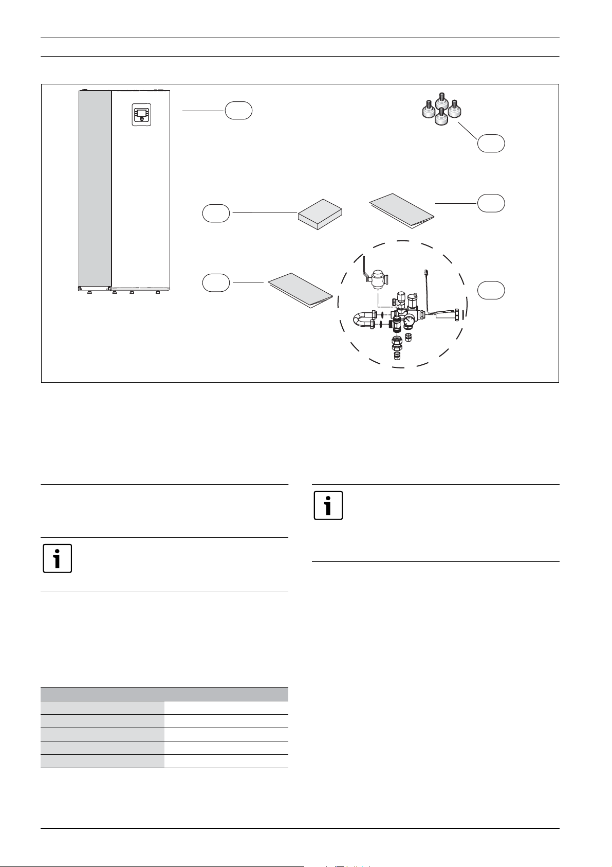
2 Standard delivery
1
2
TL1
4
Fig. 1 Standard delivery
[1] Heat pump module
[2] Legs
[3] Operating Instructions
[4] Installation instructions
[5] Safety assembly in loose parts
[T1] Outside temperature sensor
3 General
The language of the original manual is Swedish, other languages are a
translation of the original manual.
Only trained personnel may perform this installation.
The installer must comply with local rules and
regulations as well as the information in the installation
and operating instructions.
Cooling is disabled in the UK model to comply with
the regulations for RHI.
3.1 Information about the heat pump
AirModule are heat pump modules that are intended for indoor use and
for connection with outdoor AirX heat pumps.
The following combinations are possible:
AirModule AirX
E9 50
E9 70
E9 90
E15 130
E15 170
Table 2
The AirModule heat pump module has a built-in immersion heater.
3
5
6 720 810 350-01.1I
3.2 Application area
The heat pump module may only be used in closed heating systems in
accordance with EN 12828.
Other usage is prohibited. Any damage resulting from prohibited usage
is excluded from liability.
3.3 Heating system minimum volume and operation
To avoid multiple start/stop cycles, incomplete
defrosting or unnecessary alarms, a sufficient amount of
energy stored in the system is required. Energy is stored
in the heating system water volume, as well as in the
system components (radiators) and in the concrete
foundation (underfloor heating system).
Since the requirements vary for different heat pump installations and
heating systems, no general minimum volume is stated. Please refer to
the following prerequisites for all heat pump sizes instead:
Under floor heating system without a buffer cylinder
To ensure that a sufficient amount of energy is available for defrosting,
the largest room should not contain room thermostats but room
controllers should be used instead. At least 30 m
be regulated by a room controller, since the heat pump then will adjust
flow temperature automatically.
Radiator system without a buffer cylinder
To ensure that a sufficient amount of energy is available for defrosting,
there should be at least 4 water radiators of 500 W/unit in one system
without mixing valve. A room controller is recommended, since the heat
pump then will automatically adjust flow temperature.
Radiator and under floor heating systems on different circuits without a buffer cylinder
To ensure that a sufficient amount of energy is available for defrosting,
there should be at least 4 water radiators of 500 W/unit in the circuit
without mixing valve. No minimum floor surface is required for the
2
floor surface should
4
AirModule 6 720 813 268(2014/10)
Page 5

underfloor heating system circuit with mixing valve. A room controller is
recommended, since the heat pump then will automatically adjust flow
temperature.
Only circuits with mixing valve
To ensure that a sufficient amount of energy is available for defrosting, a
buffer cylinder of at least 50L is required for heat pump sizes 5-9 and of
at least 100L for heat pump sizes 13-17.
Fan convector
To ensure that a sufficient amount of energy is available for defrosting, a
buffer cylinder of at least 10L is required.
3.4 Type plate
The data plate is found on the module roof plate.
3.5 Transport and storage
The heat pump module must always be transported and stored upright.
If needed, it may be leaned temporarily.
The heat pump module may not be stored or transported in
temperatures below – 10 °C.
3.6 Heat pump module positioning
• The heat pump module is placed indoors. Pipework between the heat
pump and the heat pump module should be as short as possible. The
pipes must be insulated ( Chapter 7.16).
• Leakage drain water from the pressure relief valve should be drained
from the heat pump module to a frost protected outlet.
• The space where the heat pump module is placed must have a floor
drain.
General
3.7 Checks before installation
▶ Check that all pipe connections are intact and have not shaken loose
during transportation.
▶ Before operation of the heat pump module, the heating system and
the water heater, including the heat pump module, must be filled and
depressurized.
▶ Wiring should be kept as short as possible to protect the system from
downtime, for example during a thunderstorm.
▶ Low voltage wiring must be separated from high voltage wiring by at
least 100 mm.
3.8 Connection principle
The principle is based on floating condensation and a immersion heater
in the heat pump module. The user interface manages the heat pump
and the heat pump module according to a set heating curve.
When the heat pump is not able to heat the house on its own, the heat
pump module automatically starts the booster heater and produces
together with the heat pump the desired temperature in the house.
DHW is prioritized and is managed by a sensor TW1 in the hot water
cylinder. While the heater is heated, the heating system heating mode is
temporarily disconnected by a 3-way valve. When the hot water cylinder
is heated, the heat pump heating mode continues.
Heating and DHW mode when heat pump is inactive:
At outside temperatures below app. –20 °C (adjustable value) the heat
pump stops automatically and cannot produce hot water. The booster
heater in the heat pump module will in this case take over both the
heating mode and the DHW production. The heat pump will restart when
the temperature gets above –17 °C.
AirModule –6 720 813 268(2014/10)
5
Page 6

Technical information
4 Technical information
4.1 Technical information - heat pump module
Unit E9 E15
Electrical information
Power supply V 4001) /230
Recommended fuse size A 161) / 50
Immersion heater in steps kW 3/6/9 3/6/9/12/15
Heating installation
Connection
3)
Maximum operating pressure kPa 250 250
Minimum operating pressure kPa 50 50
Expansion vessel L 14 14
External available pressure kPa
Minimum flow L/s 0.36 0.59
Circulation pump model Grundfos UPM2 25-75 PWM Wilo Stratos Para 25/1-11 PWM
Flow max. temperature, booster
°C 85 85
only
General
Hot water cylinder volume L 190 190
Maximum operating pressure on
MPa 1
tap DHW circuit
Material Stainless steel 1.4521
IP rating IP X1
Dimensions (WxDxH) mm 600x660x1800
Weight kg 135
Table 3 heat pump module with immersion heater
1) 3N AC 50 Hz
2) 1N AC 50 Hz
3) See Connections in safety assembly
4) This depends on the type of heat pump, see tab. 11
2)
2)
400
25
1)
Cu 28 Cu 28
4)
4)
1)
6
AirModule 6 720 813 268(2014/10)
Page 7
Technical information
4.2 System configurations
The heat pump and heat pump module may be installed
only in accordance with the official system solutions
provided by the manufacturer.
Other system solutions are not allowed. Any damage and
problems resulting from prohibited installation are
excluded from liability.
4.2.1 System configuration explanations
General
Installer
module
ProControl 600 User interface
CR10H Room controller (accessories)
T1 Outside temperature sensor
CC1 Buffer cylinder (accessories)
MK2 Condensation sensor (accessories)
VC0 3-way valve (accessories)
PW2 DHW circulation pump hot water (accessories)
Table 4 General
Z1 Heating circuit without mixing valve
PC1 Circulation pump, heating circuit
T0 Flow temperature sensor (placed in the safety assembly or
Table 5 Z1
Installer module integrated into the heat pump
module
in the buffer cylinder)
Circulation pump PC1 is controlled by the control unit in the heat pump
module.
If a fresh water station is installed, it must have its own control unit.
If a buffer cylinder is used, a 3-way valve VC0 must be installed in
accordance with the system solution. The 3-way valve replaces the Tunit in the safety assembly ( Chapter 5.1.1) and is connected
electrically to terminal VC0 on the installer module.
Z2/Z3 Heating circuit with mixing valve (accessories)
MM100 Mixing valve module (controller for circuit)
PC1 Circulation pump, heating circuit 2
VC1 Mixing valve
TC1 Flow temperature sensor, heating circuit 2,3..
MC1 Thermal shut-off valve, heating circuit 2,3...
Table 6 Z2
4.2.2 Non-return valve in heating circuit
T
T
1
6 720 809 064-09.1I
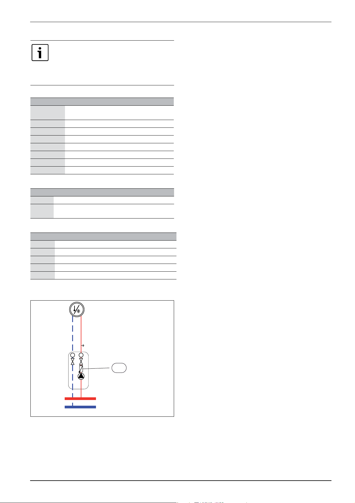
Fig. 2 Heating circuit
[1] Non-return valve
One non-return valve in each heating circuit is required for preventing
natural circulation in the heating system in summer mode. Natural
circulation may arise as the domestic hot water 3-way valve is open to
the heating system when the heat pump prepares DHW heating.
AirModule –6 720 813 268(2014/10)
7
Page 8

Technical information
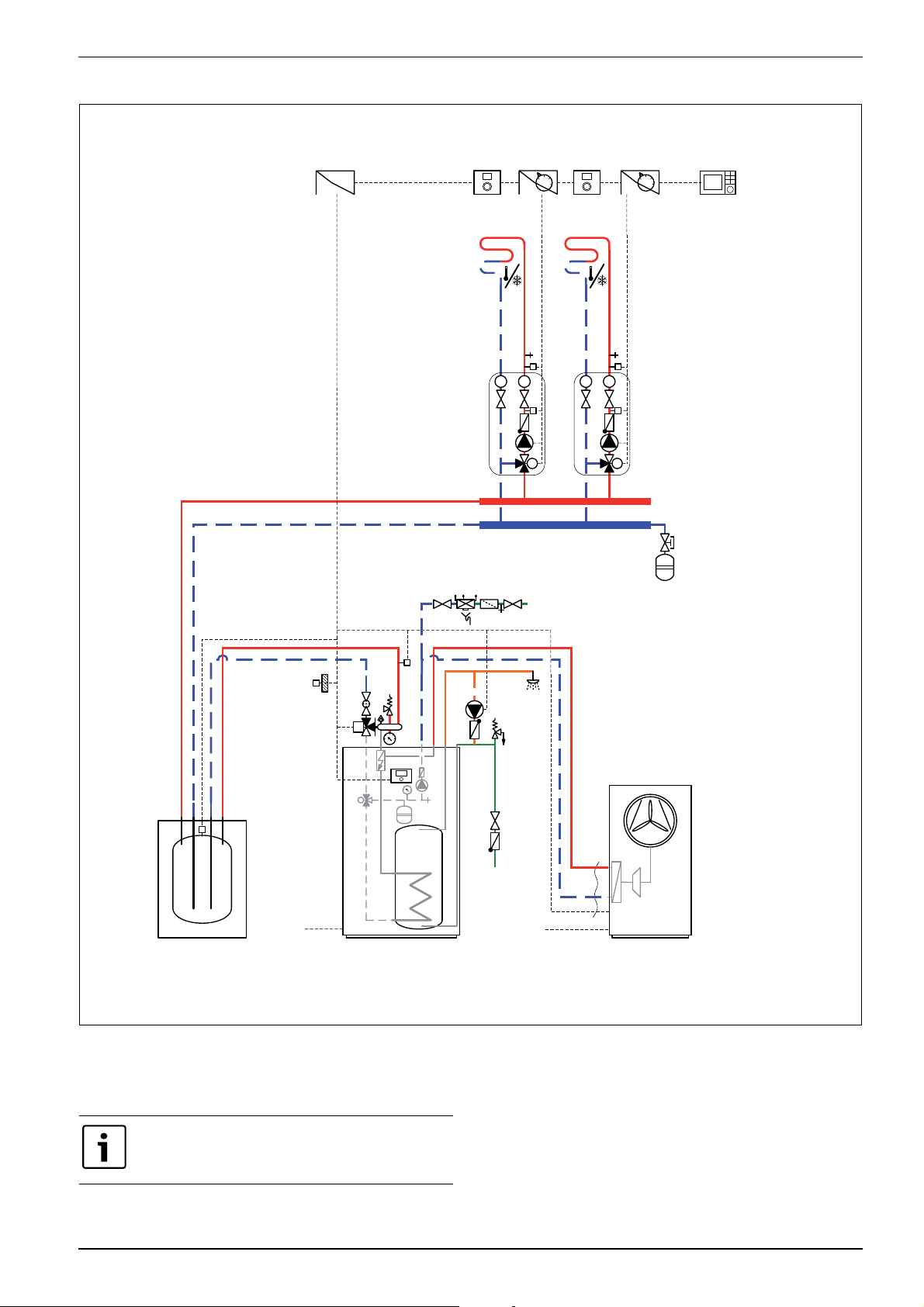
4.2.3 Heat pump with heat pump module system configuration
1
Rego 2000
4
3
HCM2000RTH2000 RTH2000Installermodul
T T
5
MC1
TC1
PC1
M
VC1
3
MK2
5
T T
PC1
T1
T0
400V AC
PW2
Airmodule E..
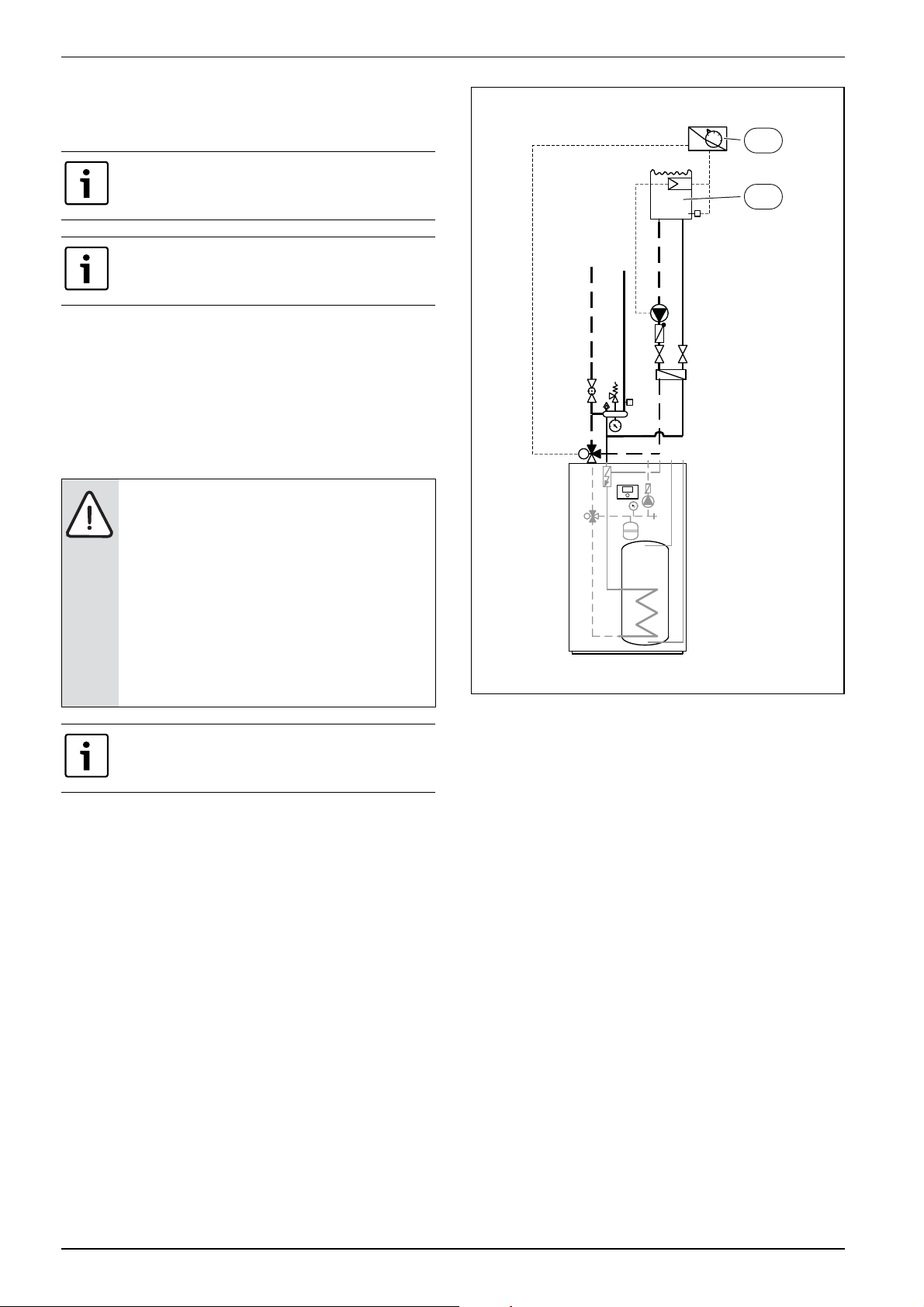
Fig. 3 Heat pump with heat pump module
[3] Installed in the heat pump module.
[4] Installed either in the heat pump module or mounted to the wall.
[5] Installed on the wall
400 /230 V AC
AirX ..
6 720 809 156-22.2I
8
AirModule 6 720 813 268(2014/10)
Page 9
4.2.4 Heat pump, heat pump module and buffer cylinder system configuration
Technical information
Installermodul
3
RTH2000
T
HCM2000
5
T
M
1
MC1
TC1
PC1
VC1
RTH2000
4
T
HCM2000
5
T
TC1
PC1
M
VC1
2
MC1
4
Rego 2000
3
MK2
B
T1
T0
BC 100/120
VC0
400V AC
M
AB
Airmodule E..
A
Fig. 4 Heat pump with heat pump module and buffer cylinder
[3] Installed in the heat pump module.
[4] Installed either in the heat pump module or mounted to the wall.
[5] Installed on the wall
PW2
400 /230 V AC
AirX ..
6 720 809 156-22.3I
The extra expansion vessel for the heating system is
designed primarily for the volume of the buffer cylinder.
AirModule –6 720 813 268(2014/10)
9
Page 10

Technical information
4.2.5 General symbol explanation
Symbol Designation Symbol Designation Symbol Designation
Pipework/Wiring
Flow - heating/solar circuit DHW Electric wire
Return - heating/solar circuit Potable water Electric wire disconnected
DHW circulation
Actuators/Valves/Temperature sensors/Pumps
Valve Differential pressure regulator DHW circulation pump
Revision bypass Pressure relief valve Non-return valve
Adjustment valve Safety assembly Temperature sensor/switch
Other
Overcurrent valve 3-way mixing valve
M
(mixing/distributing)
Overheating protection
(temperature)
Filter valve (particle filter) Thermal DHW mixing valve Outside temperature sensor
T
Shut-off valve with unintentional
closure control
Valve, motorized 3-way valve (changing, normally
M
M
M
I
II
3-way valve
(change)
closed to II)
Wireless outside temperature
sensor
...Radio (wireless)...
III
Valve, thermal 3-way valve (changing, normally
T
M
AB
A
closed to A)
B
Shut-off valve, magnetic 4-way valve
Thermometer Funnel with siphon Low loss header with sensor
T
Pressure gauge Return flow safety module in
M
Heat exchanger
accordance with EN1717
Fill / drain valve Expansion vessel with shut-off valve
Flow meter
with closure
Water filter Collector Heat meter
Air separator Heating circuit DHW outlet
Automatic air vent valve Underfloor heating circuit Relay
Compensator (devibration) Low loss header Immersion heater
Table 7 Symbols key
10
000
∏
R
J
AirModule 6 720 813 268(2014/10)
Page 11
5 Measurements, positioning distance, and pipe connections
5.1 Heat pump module dimensions and connections
>
_
400
>
_
800
Measurements, positioning distance, and pipe connections
1800 304
6 720 809 156-06.1I
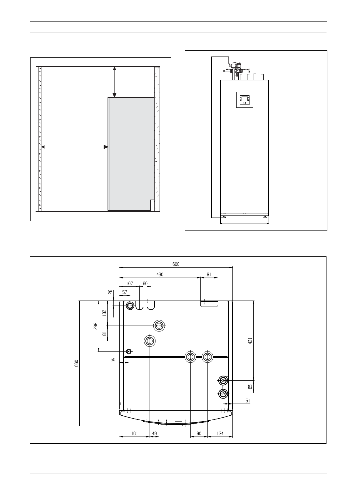
Fig. 5 Heat pump module minimum distance
There should be at least 50 mm between the heat pump module sides
and other fixed installations (walls, sinks, etc.). Ideal positioning is by an
outer wall or a middle wall.
304
Fig. 6 Heat pump module dimensions (mm)
6 720 810 350-09.1I
Fig. 7 Roof view dimensions
AirModule –6 720 813 268(2014/10)
6 720 809 156-11.2I
11
Page 12
Measurements, positioning distance, and pipe connections
7 8
<50V
5
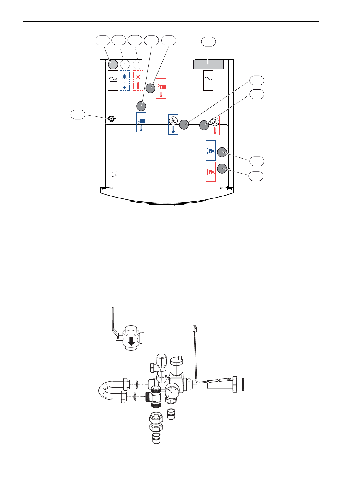
Fig. 8 Heat pump module connections
[1] Heat transfer medium out (to the heat pump)
[2] Heat transfer medium in (from the heat pump)
[3] Cold water inlet connection
[4] DHW outlet connection
[5] Cable feed to IP module
[6] Cable bus CAN-BUS and sensor
[7] Return to solar thermal system (only on the solar models)
[8] Flow from solar thermal system (only on the solar models)
[9] Return from safety group
[10] Flow to safety group
[11] Cable bus electrical connection
9 106
11
230V
400V
/
1
2
3
4
6 720 809 156-08.2I
5.1.1 Safety assembly
Fig. 9 Safety assembly delivery
6 720 809 156-12.2I
12
AirModule 6 720 813 268(2014/10)
Page 13
Regulations
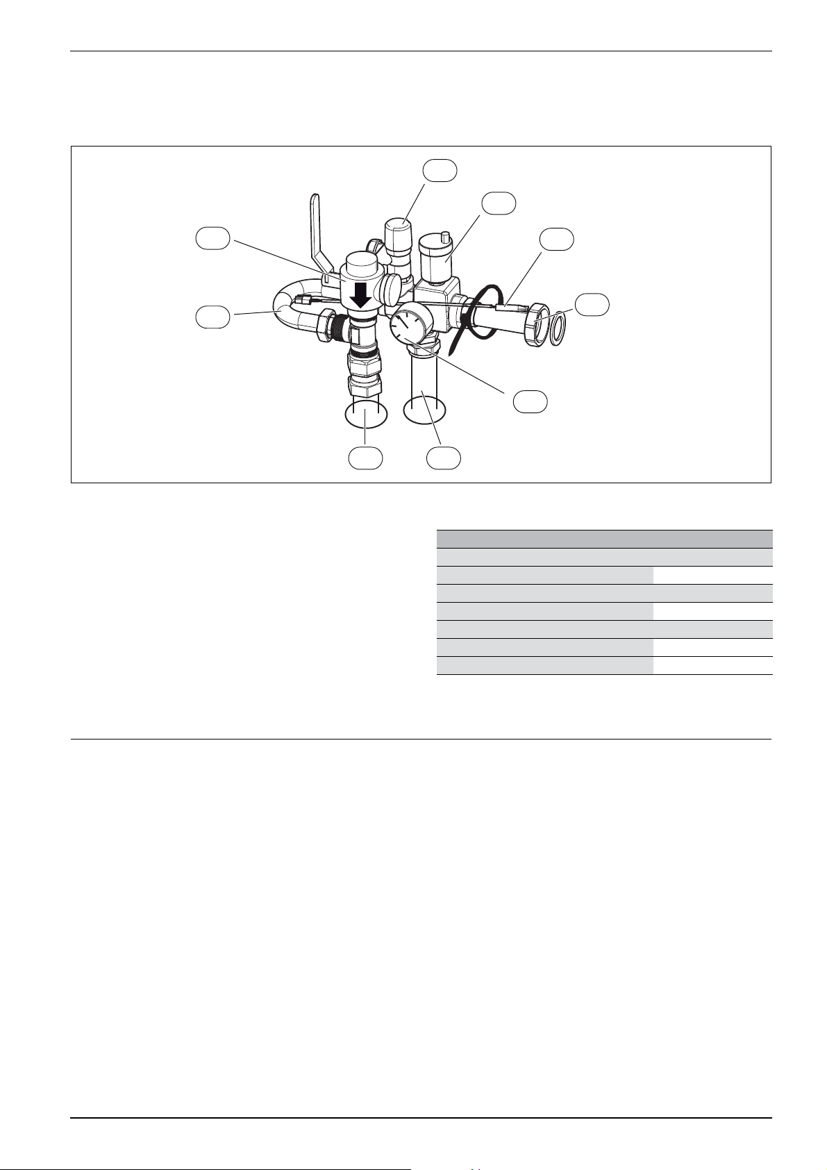
Assemble the safety assembly:
▶ First install the particle filter ([SC1], figure 10) on the T-unit.
▶ Install the other parts, but do not tighten the nuts completely on the
bypass ([4], figure 10).
SC1
4
▶ Place the flow temperature sensor in the sensor pocket ([T0],
figure 10), and secure the sensor with a cable tie.
▶ Fit the safety assembly on the heat pump module.
▶ Tighten the nuts completely on the bypass ([4], figure 10).
FC1
VL1
T0
1
GC1
23
6 720 809 156-13.3I
Fig. 10 Safety assembly fitted
[1] Circulation pump heating system connection (PC1), G1
½ (40R) adapter to heating system flow
[2] Flow to safety group
[3] Return from safety group
[4] Bypass
[SC1] Particle filter, connection G1internal thread from heating
system return
[FC1] Pressure relief valve
[VL1] Automatic air vent valve
[T0] Flow temperature sensor
[GC1] Pressure gauge
6 Regulations
The following regulations and requirements must be observed:
• Local rules and regulations, including special rules, of the
responsible power supply company
• National building regulations
• EN 50160 (Voltage properties in power grids for public distribution)
• EN 12828 (Heating systems in buildings - Design and installation of
water-based heating systems)
• EN 1717 (Water supply - Protection against pollution of potable
water)
5.2 Pipework
Pipe dimensions (mm) Heat pump module
Heating installation
Spring clip connection Cu Ø 28
Cold and hot water
Stainless spring clip connection Ø 22
Heat transfer medium
Spring clip connection Cu Ø 28
Leakage drain water/drain in both Ø 32
Table 8 Pipe dimensions
1) See Connections in safety assembly
1)
AirModule –6 720 813 268(2014/10)
13
Page 14
Installation
7 Installation
NOTICE: Risk of operating problems due to pipe
contamination!
Particulates, metal/plastic filings, flax and thread tape
residue and similar material can get stuck in pumps,
valves and heat exchangers.
▶ Avoid particulates in the pipework.
▶ Do not leave pipe parts and connections directly on
the ground.
▶ Ensure that no filings remain in the pipes following
deburring.
Only qualified installers may carry out the installation.
The installer must follow applicable rules and regulations
and recommendations from the supplier.
7.1 Detailed discharge pipe installation requirements (Combi model)
The discharge pipework must be routed in accordance with part G3 of
schedule 1 of the building Regulations.
The tundish should be vertical, located in the same space as the
unvented hot water cylinder and be as close as possible and within
600mm of the safety device e.g. the temperature relief valve. The discharge pipe from the tundish should be:
• made of metal
• at least one pipe size larger than the nominal outlet size of the safety
device (larger sizes may be required if the equivalent hydraulic
resistance exceeds that of a straight pipe 9m long - refer to BS6700)
• terminate in a safe place where there is no risk to persons in the
vicinity of the discharge, and position safely from electrical devices
• have a vertical section of pipe at least 300mm long below the tundish
before any elbows or bends in the pipework.
Maximum
Size of
Valve
discharge
outlet
size
G1/2 15 mm 28 mm Up to 18 m 1.0 m
G3/4 22 mm 35 mm Up to 18 m 1.4 m
G1 28 mm 42 mm Up to 18 m 1.7 m
pipework
D1
Size of
discharge
pipework
D2
22 mm Up to 9 m 0.8 m
35 mm Up to 27 m 1.4 m
28 mm Up to 9 m 1.0 m
42 mm Up to 27 m 1.7 m
35 mm Up to 9 m 1.4 m
54 mm Up to 27 m 2.3 m
length of
straight pipe
(no bends or
elbows)
Deduct the figure
below from the
maximum length for
each bend or elbow in
the discharge pipe
Table 9
7.2 Preparatory pipework
The safety valve drain in the heat pump module should
be secured against frost and the drain pipe should lead
to a drain.
▶ Fit heating system and cold/hot water connector pipes in the space
up to the heat pump module position.
7.3 Positioning
▶ Remove the packaging according to the instructions on the
packaging.
▶ Remove the supplied accessories.
7.4 Checklist
Each installation is different. The following check list will
provide a general description of the installation process.
6 720 806 768-05.1I
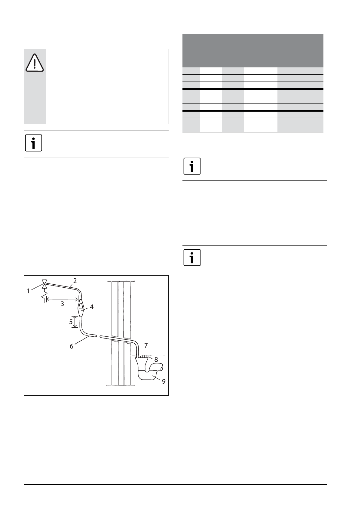
Fig. 11 Typical discharge pipe arrangement
[1] Safety device (e.g. temperature relief valve)
[2] Metal discharge pipe (D1) from temperature relief valve to tunish
[3] 600mm maximum
[4] Tundish
[5] 300mm minimum
[6] Metal discharge pipe (D2) from tundish, with continous fall
[7] Discharge below fixed grating
[8] Fixed grating
[9] Trapped gulley
1. Install the heat pump module safety assembly (Chapter 5.1.1)
and fill valve.
2. Fit the heat pump module leakage water hose(s).
3. Connect the heat pump and the heat pump module
(Chapter 7.11).
4. Connect the heat pump module to the heating system
(Chapter 7.12).
5. Install the outside temperature sensor (Chapter 7.19.3) and room
controller (optional).
6. Connect the CAN-BUS wire between the heat pump and the heat
pump module (Chapter 8.1).
7. Install any accessory (mixing module, solar module, pool module,
etc).
8. Connect EMS-BUS wire (optional) to accessories (Chapter 8.2).
9. Fill up and bleed the hot water cylinder.
10. Fill up and vent the heating system before commissioning
(Chapter 7.20).
11.Connect the heating system to the electrical system (Chapter 8).
12.Commission the heating system by managing necessary settings in
the user interface (Chapter 11).
13.Vent the heating system (Chapter 14).
14.Check that all sensors show reasonable values (Chapter 12.9.2).
15.Check and clean out the particle filter (Chapter 18).
16. Check the heating system function following commissioning
(Chapter 12.9).
14
AirModule 6 720 813 268(2014/10)
Page 15

Installation
7.5 Water quality
Heat pumps operate with lower temperatures than other heating
systems, which means that the thermal degassing is not as effective and
the oxygen content will never be as low as in an electric/oil/gas system.
This means that the heating system will be more sensitive to rust with
aggressive water.
Do not use any water additives except for pH-enhancer and keep the
water clean.
Recommended pH level is 7.5 – 9.
Water quality
Hardness < 3°dH
Oxygen content < 1 mg/L
Carbon dioxide, Co
Chloride ions, Cl- < 250 mg/L
Sulphate, So42- < 100 mg/L
Conductivity < 350 μs/cm
Table 10 Water quality
1) Electric anode (accessory) in the water heater is recommended for higher
chloride content. If electric anode is used, it has to be purchased in
connection with commissioning.
2
< 1 mg/L
1)
7.6 Heating system flushing
NOTICE: System damage due to objects in the pipes!
Objects in the pipes will decrease the flow and cause
operational problems.
▶ Flush out the system to remove all dirt residues
before connecting the heat pump and heat pump
module.
The heat pump module is a part of a heating system. Problems in the heat
pump module can be caused by poor water quality in the radiators/floor
loops or by constant system oxygenation.
Oxygen causes corrosion products in the form of magnetite and
sediment.
Magnetite has a grinding effect on the heating system's pumps, valves
and components with turbulent flows such as the condenser.
Heating systems which require regular filling or where the heating water
does not produce clear water during water sampling require measures
prior to the installation of the heat pump, e.g. supplementing the heating
system with magnetite filters and air vent valves.
7.7 Operation without heat pump (stand-alone)
The heat pump module can be put into operation without a connected
heat pump, for example, if the heat pump is installed at a later date. This
is called "stand-alone" operation.
In stand-alone mode, the heat pump module uses only the integrated
immersion heater for heating and DHW production.
If the heat pump module and the heating system are
filled before the heat pump is connected, then the heat
transfer medium in and out to / from the heat pump must
be connected to secure circulation ( [1] and [2],
Fig. 13).
▶ Open shut-off valves on the heat transfer circuit, if
applicable.
In connection with commissioning of stand-alone operation:
▶ Set Stand-alone mode in the service menu Heat pump ( Chapter
12.1).
7.8 Installation with cooling
Cooling is disabled in the UK model to comply with
the regulations for RHI.
Using cooling mode requires the installation of a room
controller (accessory).
Installation of a room controller with integrated humidity
sensor (accessory) makes cooling mode more secure as
the user interface automatically adjusts the flow
temperature in relation to the current dew point.
▶ Insulate all connections and pipes from condensation.
▶ Install a room controller, with or without an integrated moisture
sensor ( manual for the respective room controller).
▶ Install condensation sensors ( Chapter 7.18).
▶ Select automatic mode heating/cooling ( Chapter 12.3.2,)
▶ Make the necessary cooling mode settings: start temperature, start
delay, room temperature and dew point differential (offset), as well
as lowest flow ( Chapter 12.3.2).
▶ Set the temperature differential (delta) over the heat pump (
Chapter 12.1.1)
AirModule –6 720 813 268(2014/10)
15
Page 16
Installation
▶ Turn off floor circuits in moist rooms (e.g. bathrooms and kitchens)
and use relay outputs PK2 in order to govern this ( Chapter 8.4).
7.9 Installation with solar heater (only solar model)
Using solar additional heating requires installation of a
solar module (accessory).
The solar energy coil in the cylinder is intended for
maximum added heating output of 4.5 kW. Only DHW
heating is possible with the integrated coil.
▶ Install solar panels ( panel manual).
▶ Insulate all connections and pipes.
▶ Install solar module ( solar module manual).
▶ Select Yes to the question Solar thermal sys installed during
commissioning ( Chapter 11.2).
▶ Make the necessary settings for the installed solar thermal system
( Chapter 12.6)
7.10 Installation with pool
NOTICE: Risk of malfunction!
Cooling mode is not possible if the mixing valve for the
pool is placed in a wrong position in the system. Even
other functional disturbances might arise. The mixing
valve for the pool must not be positioned so that it can
block the safety valve on the flow line.
▶ Install the mixing valve for pool on the return pipe to
the heat pump module ( [VC1] Bild 12).
▶ Install the T-pipe on the flow line from the heat pump
module, before the bypass in the safety assembly.
▶ The pool mixing valve may not be installed as a
heating circuit.
Installation of a pool module (accessory) is demanded to
use pool heating.
HS
VC1
M
Fig. 12 Pool installation example
[1] Pool module
[2] Pool
[VC1] Pool mixing valve
[HS] Heating system
1
1
2
6 720 810 931-10.3I
▶ Install the pool ( instructions for the pool).
▶ Install the mixing valve for pool.
▶ Isolate all pipes and connections.
▶ Install the pool module ( instruction for the pool module). Please
observe that the hydraulic solution that is presented in that can not
be used.
▶ Set the mixing valve running time at commissioning ( Chapter
11.2).
▶ Make necessary settings for the pool heating ( Kapitel 12.5).
16
AirModule 6 720 813 268(2014/10)
Page 17
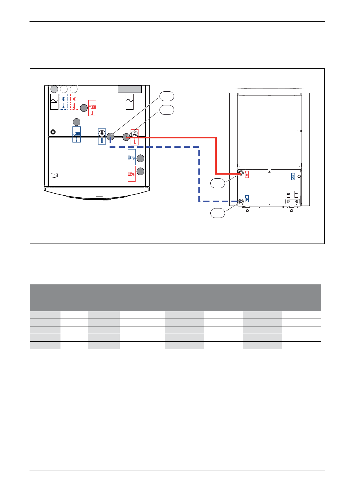
7.11 Connecting the heat pump module to the heat pump
Insulate pipes and connections against condensation if cooling is to be
used.
▶ Select pipe size according to table 11.
<50V
230V
/
400V
Installation
▶ Connect the return to the heat pump [4] to the heat transfer medium
out [1] figure 13.
▶ Connect the flow from the heat pump [3] to the heat transfer medium
in [2] Figure 13.
1
2
3
<50V 230V
/
400V
4
6 720 809 156-14.1I
Fig. 13 Heat pump connections heat pump module
[1] Heat transfer medium out (to the heat pump)
[2] Heat transfer medium in (from the heat pump)
[3] Flow from heat pump
[4] Return to heat pump
Heat
transfer
Heat pump
output (kW)
fluid delta
(K)
Nominal flow
(L/s)
Maximum pressure
drop (kPa)
1)
550.32 68 28 60
750.33 55 14 33 60
950.43 40 82160
13 5 0.62 56 14 60 60
17 5 0.81 18 15 60
Table 11 Pipe dimensions and max. pipe length for connection of heat pump to heat pump module
1) For pipes and components between the heat pump module (indoor unit) and heat pump (outdoor unit).
AX20
inner-Ø 15 (mm)
AX25
inner-Ø 18 (mm)
Maximum pipe length PEX (m)
AX32
inner-Ø 26 (mm)
AX40
inner-Ø 33 (mm)
AirModule –6 720 813 268(2014/10)
17
Page 18
Installation
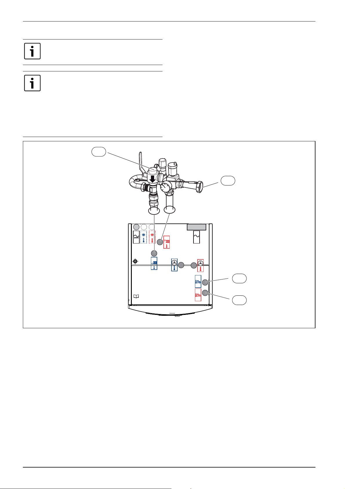
7.12 Connecting the heat pump module to the heating system and tap water
Pressure relief valve, non-return valve, and fill valve must
be installed on the tap DHW circuit (not included).
If there is not enough room to install the safety assembly
directly on the heat pump module connections:
▶ Extend the connections by max. 50 cm.
▶ Do not angle the connections downwards.
▶ Do not install any shut-off valves between the safety
assembly and the heat pump module.
▶ The particle filter can be installed at a bend to the left.
▶ Bends can be installed between the safety group and
the connection for the circulation pump.
Insulate the connections and pipes to the heating system from
condensation if cooling is used.
▶ Install the safety assembly ( Chapter 5.1.1).
▶ Install the pressure relief valve and non-return valve with a fill valve
for tap DHW.
▶ Drain leakage drain hoses from the pressure relief valves into a frost
protected drain.
▶ Connect the heating system circulation pump to [1] figure 14.
▶ Connect the heating system return to the particle filter [SC1]
figure 14.
▶ Connect cold water inlet to [2] figure 14.
▶ Connect DHW outlet to [3] figure 14.
▶ Connect the heating system flow to the circulation pump.
SC1
1
<50V
Fig. 14 Heating system and DHW connections heat pump module
[1] Connection for circulation pump PC1 (flow to heating system)
[2] Cold water inlet connection
[3] DHW outlet connection
[SC1] Particle filter (return from heating system connection)
230V
/
400V
2
3
6 720 809 156-05.1I
18
AirModule 6 720 813 268(2014/10)
Page 19

Installation
The heating system circulation pump is required and
selected based on the system pressure drop and flow
requirements.
PC1 must always be connected to the installer module in
the heat pump module according to the circuit diagram.
Relay output max. load for circulation pump PC1: 2 A,
cos>0.4. Higher load requires installation of an
intermediate relay.
7.15 DHW circulation pump PW2 (accessory)
Settings for the circulation pump PW2 is done in the control unit
(Chapter 12.4).
7.16 Insulation
NOTICE: Damage due to freezing!
In case of a power outage the water in the pipes may
freeze.
▶ Use at least 19 mm insulation for outside pipework.
▶ Use at least 12 mm insulation for inside pipework.
This is important for safe and efficient DHW heating.
1
6 720 809 156-10.1I
Fig. 15 Drain hose
[1] Drain hose
▶ Connect the drain hose with a leakage drain hose to a frost protected
drain.
7.13 Low energy pump for heat transfer medium (PC0)
PC0 heat transfer pump is PWM operated (RPM controlled). The pump
settings are managed on the heat pump module control panel.
Circulation pump speed is automatically adjusted for optimal operation.
7.14 Circulation pump for the heating system (PC1)
NOTICE: Damage due to deformation!
The circulation pump connecting pipe in the safety
assembly may bend if it is subject to heavy weight
pressure for an extended period of time.
▶ Use appropriate mounting installation for the heating
system pipes and DHW circulation pump to support
the safety assembly connection.
All heat conducting lines must have suitable heat insulation according to
applicable norms.
During cooling, all connections and lines must be condensation
insulated according to applicable norms.
7.17 Several heating circuits (mixing valve module accessory, see separate instructions)
The user interface can handle a heating circuit without a mixing valve in
standard configuration. A mixing valve module is required for each
circuit if additional circuits are installed.
▶ Install the mixing valve module, mixing valve, circulation pump and
other components in accordance with the selected system solution.
▶ Connect the mixing valve module to terminal EMS on the installer
module in the heat pump module electric box.
▶ Make settings for several heating circuits in accordance with Chapter
12.3.2.
If there is already a connection on the EMS terminal, the connection is
made parallel to the same terminal in accordance with Fig. 16. If several
EMS modules are installed in the system, these must be connected in
accordance with Fig. 33, Chapter 8.12.
7.18 Installation of condensation sensor (accessories)
NOTICE: Damage due to moisture!
Cooling below dew point will result in condensation on
the surrounding material (floor).
▶ Do not use the underfloor heating system for cooling
below dew point.
▶ Correctly adjust the flow temperature as described
in Chapter 12.3.2.
The condensation guard function will stop the cooling if condensation
develops on the heating system pipes. Condensation will develop during
cooling if the heating system temperature is lower than current dew
point temperature.
AirModule –6 720 813 268(2014/10)
19
Page 20

Installation
The dew point will vary depending on temperature and humidity. The
higher the humidity, the higher flow temperature is required to remain
above dew point and avoid condensation.
The condensation sensors will send a signal to the operating system
when they sense condensation and stop the cooling.
Instructions for installation and handling are included with the
condensation sensor.
7.18.1 Condensation monitoring, fan coils only
NOTICE: Damage due to moisture!
Moisture may be transferred to surrounding materials if
there are gaps in the condensation insulation.
▶ Apply condensation insulation to all pipes and
connections up to the fan element for cooling.
▶ Use condensation insulation material that is
intended for condensation cooling systems.
▶ Connect the drain to the drain outlet.
▶ Do not use condensation guard.
If only fan elements with drainage and condensation insulated pipes are
used, the flow temperature can be set to 7 °C. The lowest recommended
temperature is 10 °C for balanced cooling as the freeze guard is
activated at 5 °C.
7.19 Temperature sensor installation
The user interface in the delivery configuration automatically regulates
the flow temperature based on the outdoor temperature. A room
controller can be installed for greater comfort. If cooling mode is used, a
room controller is a must.
7.19.1 Room controller (accessories, see separate instructions)
If the room controller is installed after the system has
been put into operation, it must be selected as room
controller for heating circuit 1 in the start-up menu (
Chapter 11.2).
▶ Install the room controller in accordance with its instruction.
▶ Connect the room controller to a terminal EMS on the installer
module in the heat pump module electric box.
▶ Set room controller CR10 as remote control before the installation is
put into operation ( Room controller's instruction). CR10H does
not have this option.
▶ Make circuit settings on the room controller before the installation is
put into operation ( Room controller's instruction).
▶ Indicate when the installation is put into operation that room
controller (CR10 or CR10H) has been installed ( Chapter 11.2) as
a user interface for heating circuit 1.
▶ Make room temperature settings according to Chapter 12.3.2.
If there is already a connection on the EMS terminal, the connection is
made parallel to the same terminal in accordance with Fig. 16. If several
EMS modules are installed in the system, these must be connected in
accordance with Fig. 33, Chapter 8.12.
EMS NSC/IP
6 720 809 156-42.1I
Fig. 16 EMS connection on installer module
7.19.2 Flow temperature sensor T0
The sensor is delivered with the heat pump module.
▶ Fit the sensor in the pocket on the safety assembly ( figure 10) or
on the buffer cylinder if one is installed.
▶ Connect flow temperature sensor T0 to terminal T0 on the installer
module in the heat pump module electric box.
7.19.3 Outside temperature sensor T1
A screened cable must be used if the outside
temperature sensor cable is longer than 15 m. The
screened cable must be grounded in the inside unit. The
max. length of a screened cable is 50 m.
The outside temperature sensor cable must meet the following minimum
requirements:
Cable diameter: 0.5 mm
2
Resistance: max. 50 ohm/km
No. of conductors: 2
▶ Install the sensor on the cold side of the house, normally north facing.
It must be protected from direct sunlight, ventilation air or anything
that can affect the temperature measurement. The sensor must not
be installed directly beneath the roof.
▶ Connect outdoor temperature sensor T1 to terminal T1 on the
installer module in the heat pump module electric box.
20
AirModule 6 720 813 268(2014/10)
Page 21

Installation
N
NE
NW
W
SW
(min 2m)
H
H
2
/
1
E
SE
S
Fig. 17 Outside temperature sensor positioning
6 720 809 156-23.1I
AirModule –6 720 813 268(2014/10)
21
Page 22

Installation
7.20 Heat pump and heat pump module filling
When filled, the system has to be thoroughly vented.
▶ Fill the system according to these instructions.
▶ Connect the system to power as described in
Chapter 8.
▶ System commissioning as described in Chapter 11.
▶ Vent the system as described in Chapter 14.
PC1
SC1
VL1
VW2
VC1
T
VC2
T
Z1
GC1
VW1
PC0
VC0
VW3
Fig. 18 Heat pump module and heating system
1. Disconnect the heat pump and heat pump module power.
2. Activate automatic venting of VL1 by unscrewing the screw a couple
of turns without removing it.
3. Close the heating system valves; particle filter SC1 and VC1.
4. Connect one end of a hose to VC0 and the other end to a drain. Open
the drain valve VC0.
5. Open the cold water valve VW3 and the fill valve VW2 to fill the heat
pump pipes.
6. Continue filling until only water comes out of the hose by the drain
and the outdoor unit does not form bubbles any more.
7. Close the drain valve VC0 and fill valve VW2.
8. Move the hose to the heating system drain valve VC2.
9. Open the particle filter SC1, the drain valve VC2 and the fill valve
VW2 to fill the heating system.
10.Continue filling until only water comes out of the hose by the drain
and the heating system does not form bubbles any more.
11.Close the drain valve VC2.
6 720 809 156-22.1I
12. Open the heating system fill valve VW2 and keep filling until the
pressure gauge GC1 shows 2 bar.
13.Close the fill valve VW2.
14.Remove the hose from VC2.
15.chapter 14.
22
AirModule 6 720 813 268(2014/10)
Page 23

Electric installation
8 Electric installation
DANGER: Risk of electric shock!
The heat pump module components conduct electricity.
▶ Turn off the main power before any electrical work.
NOTICE: The installation will get damaged if the power is
connected without water.
Components in the heating system can overheat if the
power is connected before it has been filled up with
water.
▶ Fill and pressurize the water heater and the heating
system before connecting the installation to power.
The heat pump module electrical connection must be
disconnected safely in accordance with the wiring rules.
▶ Install a separate safety switch that disconnects all
power to the heat pump module. In case of separate
power supplies you will need one safety switch for
each supply.
The compressor warms up before it starts. This can take
up to 2 hours, depending on the outside temperature.
The requirement is that the compressor temperature
(TR1) is 10 K above the air intake temperature (TL2).
The temperatures are visible in the Diagnostics menu (
Chapter 12.9).
For recommended fuse sizes, see Technical information
(Chapter 4.1).
The heat pump and the heat pump module are connected by a
communications wire, CAN-BUS.
A suitable cable for external cable installation is wire LIYCY (TP)
2x2x0.75, or equivalent. An alternative cable should have a cross
section area of at least 0.75 mm
2
, and be a duplex cable, screened and
approved for outside use. The screen should only be grounded in one
end (indoor unit) and to the chassis.
Maximum cable length is 30 m.
The connection between the circuit boards is by four wires, because the
12V-supply between the circuit boards must also be connected. The
circuit boards have markings for both the 12V and CAN-BUS
connections.
Switch Term is used to mark the start and end of a CAN-BUS loop.
Ensure that the correct circuit board is terminated and that all other
switches are in the opposite position.
6 720 809 156-24.1I
Fig. 19 Termination CAN-BUS
[On] Terminated CAN-BUS
[Off] Not terminated CAN-BUS
8.2 EMS-BUS
▶ Choose cable area and type that represent the fuse protection and
wire mode.
▶ Connect the heat pump according to the circuit diagram. Never
connect any other consumers.
▶ If the heat pump is connected through a circuit breaker, then a
separate circuit breaker for the heat pump must be used. Please
observe current regulations.
▶ Observe the colour coding when replacing circuit boards.
8.1 CAN-BUS
NOTICE: Malfunction due to electrical disturbances!
High voltage lines (230/400 V) close to a
communications line can cause the heat pump module
to malfunction.
▶ Install screened CAN-BUS wire away from a power
cord. Minimum distance 100 mm. Cabling together
with bus lines is allowed.
NOTICE: The system will be damaged if the 12 V- and
the CAN-BUS connections are confused!
The communication circuits are not designed for 12 V
constant voltage.
▶ Check that the four cables are connected to plugs
with corresponding rating on the printed circuit
board.
NOTICE: Malfunction due to electrical disturbances!
High voltage lines (230/400 V) close to a
communications line can cause the heat pump module
to malfunction.
▶ Install the EMS-BUS wire away from a power cord.
Minimum distance 100 mm. Cabling together with
bus lines is allowed.
EMS-BUS and CAN-BUS are not compatible.
▶ Do not connect EMS-BUS units with CAN-BUS units.
The user interface HPC400 and the installer module in the heat pump
module are connected by EMS-BUS.
The user interface is powered via the BUS cable. Polarity is not important
for the two cables in the EMS-BUS.
In case of EMS-BUS accessories it is important to note that (please also
refer to the installation instructions for each accessory):
▶ If several BUS units are installed, they must be separated by at least
100 mm.
▶ If several BUS units are installed, they must be connected in a series
or a star network.
▶ Use a cable with a cross section area of at least 0.5 mm
2
.
▶ In case of external inductive interferences (e.g. from PV systems),
use screened cables. The screen should only be grounded in one end
and to the chassis.
AirModule –6 720 813 268(2014/10)
23
Page 24

Electric installation
8.3 Printed circuit board handling
Circuit boards with control electronics are sensitive to discharges of
static electricity (ESD – ElectroStatic Discharge) when handled. To
prevent damaging the components, special care is therefore required
when handled.
CAUTION: Damage due to static electricity!
▶ Wear a grounded antistatic wrist strap when
handling unenclosed printed circuit boards.
6 720 614 366-24.1I
Fig. 20 Antistatic wrist strap
Damage is usually latent, and a circuit board can operate correctly
during commissioning but show signs of problems later. Charged
objects may only be problematic if they are in close proximity to the
electronics. Keep a distance of at least one metre from expanded
polystyrene, protective plastic and other packaging, synthetic material
(e.g. fleeces) and similar before starting work.
A method for good ESD protection is a ground-connected bracelet when
handling electronics. This bracelet must be put on before opening the
screened metal bag/packaging or before exposing an installed board.
The bracelet must be worn until the circuit board is enclosed in its screen
packaging or closed electric box. Replaced, returned circuit boards must
be handled in the same way.
8.4.1 External outputs
NOTICE: Damage due to incorrect connection!
Connections intended for a different voltage or current
can damage electrical components.
▶ Only add connections to the heat pump module
external outputs that are compatible with 5 V and 1
mA.
▶ If an intermediate relay is required, use only relays
with gold-plated plugs.
External inputs I1, I2, I3 and I4 can be used to remotely manage certain
functions in the user interface.
The functions that are activated by the external inputs are described in
chapter 12.1.2.
The external input is connected either to a power switch for manual
activation or to operating equipment with a relay output for 5 V.
8.5 Accessories
CAN-BUS connected accessories, e.g. power guard, are connected to
the installer card in the heat pump module parallel on the CAN-BUS
connection to the heat pump. They can also be connected in series with
other CAN-BUS connected units.
8.6 Connecting the heat pump module
▶ Remove the front panel.
▶ Remove the electric box cover.
▶ Feed the connecting cables through the cable feed in the ceiling and
to the electric box. Use an extension spring, if required.
▶ Feed the cables so that the electric box can be tilted forward.
▶ Connect the cables according to the circuit diagram.
▶ Put the electric box cover and the heat pump module front panel
back.
8.4 External connections
To avoid inductive interference, all low voltage conductors (measure
current) should be installed with a minimum distance of at least 100 mm
from the conducting 230V- and 400V cables.
If the temperature sensor conductor has to be extended, the following
conductor diameters should be used:
• Up to 20 m long cable: 0.75 to 1,50 mm
• Up to 30 m long cable: 1.0 to 1,50 mm
The relay output PK2 is active during cooling and can be used to manage
the exchange between cooling /heating of a fan convector or a
circulation pump or to regulate floor heating circuits in moist rooms.
Output VC0 is active during cooling and is used to manage a 3-way valve
to recirculation, to facilitate the exchange between DHW heating and
cooling.
Relay output max. load: 2A, cos>0.4. Higher load
requires installation of an intermediate relay.
2
2
2
Fig. 21 Cable feed
[1] Cable bus electrical connection
[2] Cable bus CAN-BUS and sensor
1
6 720 809 156-23.2I
24
AirModule 6 720 813 268(2014/10)
Page 25

8.7 Electric box layout
Electric installation
5
4 3
Fig. 22 Electric box layout
[1] Terminals
[2] Automatic fuses (only 15 kW model)
[3] Contactors K1, K2, K3
[4] Overheating protection reset
[5] Installer module
8.7.1 Terminal connections in electric box 9 kW immersion heater 3N~, standard setting
1
2
6 720 809 156-07.2I
Fig. 23 Terminal connections in electric box
[1] 400 V 3 N~ 16 A, input
[2] 230 V 1 N~, heat pump 5/7/9
[3] 230 V 1 N~, EMS Plus accessories
Immersion heater only on L1 and L2 during heat pump
mode. Otherwise the heat pump must have a separate
power supply from the distribution board.
1
2
3
6 720 809 156-16.3I
AirModule –6 720 813 268(2014/10)
25
Page 26

Electric installation
8.7.2 Terminal connections in electric box 9 kW immersion heater 1N~, see bridge placement
2 1
Fig. 24 Terminal connections in electric box
[1] 230 V 1 N~ 50 A, input
[2] 230 V 1 N~, EMS Plus accessories
The heat pump has a separate power supply from the
distribution board 230 V 1 N~16 A.
6 720 809 156-32.1I
8.7.3 Terminal connections in electric box 15 kW immersion heater 3N~, standard setting
1
2
3
Fig. 25 Terminal connections in electric box
[1] 400 V 3 N~ 25 A, input
[2] 230 V 1 N~, EMS Plus accessories
[3] 400 V 3 N~, heat pump 13/17
26
6 720 809 156-17.3I
Max. 9 kW immersion heater during heat pump mode.
Otherwise the heat pump must have a separate power
supply from the distribution board.
AirModule 6 720 813 268(2014/10)
Page 27

8.7.4 Circuit diagram 9 kW immersion heater 3N~, standard setting
1 2 3
Fig. 26 Circuit diagram 9 kW 3N~
[1] Distribution board
[2] Heat pump module 9 kW, 400 V 3 N~
[3] Heat pump 5/7/9, 230 V 1 N~
[PC1] Heating system circulation pump
[T0] Flow temperature sensor
[T1] Outside temperature sensor
Immersion heater L1-L2, heat pump L3. Immersion
heater L3 blocked during heat pump mode.
Electric installation
6 720 809 156-33.2I
8.7.5 Circuit diagram 9 kW immersion heater 1N~
1 2 3
Fig. 27 Circuit diagram 9 kW 1N~
[1] Distribution board
[2] Heat pump module 9 kW, 230 V 1 N~
[3] Heat pump 5/7/9/13, 230 V 1 N~
[PC1] Heating system circulation pump
[T0] Flow temperature sensor
[T1] Outside temperature sensor
6 720 809 156-35.2I
AirModule –6 720 813 268(2014/10)
27
Page 28

Electric installation
8.7.6 Circuit diagram 15 kW immersion heater 3N~, standard setting
1
Fig. 28 Circuit diagram 15 kW 3N~
[1] Distribution board
[2] Heat pump module 15 kW, 400 V 3 N~
[3] Heat pump 13/17, 400 V 3 N~
[PC1] Heating system circulation pump
[T0] Flow temperature sensor
[T1] Outside temperature sensor
2 3
6 720 809 156-34.2I
28
AirModule 6 720 813 268(2014/10)
Page 29

8.8 Power supply heat pump and heat pump module 9 kW 3N~
1
2
Electric installation
3
4
Fig. 29 Power supply heat pump and heat pump module 9 kW
[1] Input 400 V 3 N~
[2] User interface
[3] Immersion heater alarm output ([2] Fig. 31)
[4] Installer module operating voltage ([1] Fig. 31)
[EE] Immersion heater
[FE] Immersion heater overheating protection
[F1] Terminal fuse
[P] Pressure switch
[K1] Contactor step 1
[K2] Contactor step 2
[K3] Contactor step 3
AirModule –6 720 813 268(2014/10)
6 720 809 156-36.2I
Connection on: L1-L2-L3-1N-PE.
Feed heat pump: 2L3-2N-PE.
User interface: L-N-PE
• Immersion heater during compressor mode: 2-4-6 kW (K3 blocked)
• Only immersion heater, compressor off: 3-6-9 kW
29
Page 30

Electric installation
8.9 Power supply heat pump and heat pump module 15 kW
1
2
3
4
5
Fig. 30 Power supply heat pump and heat pump module 15 kW
[1] Input 400 V 3 N~
[2] User interface
[3] Heat pump
[4] Immersion heater/pressure switch alarm output ([2] Fig. 31)
[5] Installer module operating voltage ([1] Fig. 31)
[F1] Terminal fuse
[F2] Heat pump fuse
[EE] Immersion heater
[FE] Immersion heater overheating protection
[P] Pressure switch
30
6 720 809 156-38.2I
[K1] Contactor step 1
[K2] Contactor step 2
[K3] Contactor step 3
• Immersion heater: 3-6-9-12-15 kW
Delivered connected
Connected during installation/
accessories
AirModule 6 720 813 268(2014/10)
Page 31

8.10 Installer module circuit diagram
2
Electric installation
3
1
Fig. 31 Installer module circuit diagram
[I1] External input 1
[I2] External input 2
[I3] External input 3
[I4] External input 4
[MK2] Condensation sensor
[PC0] Circulation pump PWM signal
[T0] Flow temperature sensor
[T1] Outside temperature sensor
[TW1] DHW temperature sensor
[TC0] Return heat transfer medium temperature sensor
[TC1] Flow heat transfer medium temperature sensor
[EW1] Immersion heater start signal in hot water cylinder (external)
[FE] Overheating protection alarm
[FW0] Anode 230 V (accessories)
[K1] Immersion heater contactor EE1
[K2] Immersion heater contactor EE2
[K3] Immersion heater contactor EE3
[F50] Fuse 6.3 A
[PC0] Heat transfer medium circulation pump
AirModule –6 720 813 268(2014/10)
6 720 809 156-15.2I
[PC1] Heating system circulation pump
[PK2] Cooling season relay output 230 V
[PW2] Hot water DHW circulation pump
[VC0] Recirculation exchange valve
[VW1] Heating/DHW exchange valve
[1] 230 V~ operating voltage ([5] Fig. 30 or [4] Fig. 29)
[2] Immersion heater/pressure switch alarm output ([4] Fig. 30
or [3] Fig. 29)
[3] CAN BUS to heat pump (I/O module card)
Relay output max. load PK2: 2 A, cos>0.4. Higher load
requires installation of an intermediate relay.
Delivered connected
Connected during installation/
accessories
31
Page 32

Electric installation
8.11 Heat pump/heat pump module circuit diagram
9kW
1
2
15kW
2
3
87
6
5
Fig. 32 Heat pump/heat pump module circuit diagram
[1] Heat pump module
[2] Heat pump
[3] IP module
[4] Accessories (extra heating circuit, pool, sun, etc.)
[5] Room controller (accessories)
[6] User interface
[7] Addressing with 9 kW immersion heater (standard setting)
[8] Addressing with 15 kW immersion heater (standard setting)
4
6 720 810 350-10.1I
32
Delivered connected
Connected during installation/
accessories
AirModule 6 720 813 268(2014/10)
Page 33

8.12 Connection option EMS bus
A B C
Electric installation
1
2
2
1
2
2
1
2
2
2
2
Fig. 33 Connection option EMS bus
[A] Star network or serial connection with external coupling box
[B] Star network
[C] Serial connection
[1] Installer module
[2] Accessory modules (for example: Room Controller, Mixing Valve
Module, Solar Module)
2
2
2
2
6 720 809 156-43.1I
AirModule –6 720 813 268(2014/10)
33
Page 34

User interface
9 User interface
9.1 Product description
• The user interface will manage a heating system with max. four
heating/cooling circuits, DHW heating with solar energy and heating
from solar power.
• In heat pump mode, optimized operation without time program will
provide the lowest energy consumption.
• The user interface can also operate according to a time program:
– Heating: 2 time programs for each heating circuit with two break
points per day. Heat circuits 2 to 4 can only change to heating
mode when heating circuit 1 is in heating mode if there is no
buffer cylinder installed.
– DHW: a time program for DHW heating.
• The user interface shows information from the heat pump module
and the heating system. It is also used to modify settings.
• After 1½ hour of operation the user interface has a battery life of at
least 8 hours. If a power outage lasts longer than the battery life, the
time and date settings will be erased. All other settings are saved.
• The functional scope and thus the menu structure of the user
interface are determined by the structure of the system. Reference to
the importance of the system structure to the functions will be made
in relevant places. Setting ranges and standard settings may not
correspond with the information in these instructions.
9.1.1 Control modes
The following main control modes are available for heating:
• Outside temperature compensated control: automatic flow
temperature control based on outside temperature.
• Outside temperature compensated control influenced by room
temperature: automatic flow temperature control based on outside
temperature and room temperature. A room controller must be
installed in the reference room.
If the cooling mode is active, it will be set to an adjustable constant
temperature.
Further information on control modes and settings that influence control
( chapter 12.3, page 44).
• Room controller CR10H as a separate room controller, which
measures relative humidity (for heating/cooling circuits)
• MM100: Module for heating and cooling circuits with mixing valve
• MP100: Module for heat pump heated pool
• MS100: Module for solar energy DHW heating
• MS200: Module for extended solar thermal systems
Instructions validity for modules supporting EMS plus
These instructions also apply to the user interface in combination with
heating/cooling circuit module MM100 (accessories).
Additional setting options may be found in some menus, if your heating
system is equipped with other modules (e.g. solar module, accessories).
These setting options are described in the module technical information.
9.2 Important notices on usage
WARNING: Risk of scalding!
If thermal disinfection has been activated to avoid
legionella, the hot water is heated once to in excess of
65 °C. The factory setting for the hot water temperature is
60 °C. There is a risk of scalding at the draw-off points if
the temperature is set higher than this.
▶ Make sure that a mixing device that prevents scalding
is installed. If in doubt, ask your contractor.
NOTICE: Floor damage!
▶ If using underfloor heating, ensure that the floor type
max. temperature is not exceeded.
▶ Optionally, install an extra temperature switch, and
connect it to one of the external inputs.
• Only products from the same distributor may be used within the EMS
BUS system.
9.3 Optional accessories
For details regarding suitable accessories, please refer to the catalogue/
price list.
Function modules and user interfaces in the control system EMS plus:
• Room controller CR10 as a separate room controller
34
AirModule 6 720 813 268(2014/10)
Page 35

10 Basic principles of operation
Basic principles of operation
10.1 Key and symbol overview
If the display is turned off, it will turn on when a key is
used and a function executed. Quickly press the selector
3
2
fav
menu
info
1
4
5
6
to turn on the display. If you don't use any keys, the
display will turn back off.
7
6 720 810 300-
Fig. 34 Keys
Pos. Section Designation Explanation
1 Favourites key ▶ Press this key to show favourite functions for heating/cooling circuit 1.
fav
2 Extra DHW key ▶ Press this key to activate the extra DHW function ( user interface operating instructions).
3 DHW key ▶ Press this key to activate the DHW operating mode ( user interface operating instructions).
4 Menu key ▶ Press this key to enter the main menu ( user interface operating instructions).
menu
▶ Keep this key pressed down to change Favourites menu settings ( User interface operating instructions).
5 Info key When a menu is shown:
info
▶ Press this key for more information about the selected item.
When standard display is active:
▶ Press this key to enter the information menu ( user interface operating instructions).
6 Return key ▶ Press this key to return to the previous menu or to cancel changes.
For maintenance or when an error has been detected:
▶ Press this key to switch between standard display and error message.
▶ Keep this key pressed down to switch between a menu and the standard display.
7 Selector ▶ Turn the selector to change a set value (e.g. the temperature) or to select a menu or item.
When the display is off:
▶ Press the selector to turn on the display.
When the display is on:
▶ Press the selector to open a selected menu or item, or confirm a set value (e.g. temperature) or a message, or to
close a pop-up window.
When standard display is active and the display is on:
▶ Press the selector to activate the input window for heating/cooling circuit options in the standard display (only
valid for systems with at least two heating/cooling circuits, User interface operating instructions).
Table 12 Keys
AirModule –6 720 813 268(2014/10)
35
Page 36

Basic principles of operation
10.2 Display symbols overview
2
1
7
3
4
5
6
6 720 811 136-01.1O
Fig. 35 An example of what the standard display might look like in a
system with several heating/cooling circuits
Pos. Symbol Designation Explanation
1 Temperature Shows current flow temperature (heat pump module temperature)
2 – Information line Displays time of day, day of the week and date.
3 Other temperature
indicator
4 – Text information E.g. the designation of the currently displayed temperature ( [1]). No designation is displayed for room
5 Key lock If key lock is enabled, the key symbol appears on the display.
6 Information graphic Displays information symbols, showing the user what functions are currently active in the system.
Displays an additional temperature, e.g. outside temperature, solar panel temperature, or the DHW system
temperature ( user interface operating instructions).
temperature. If an error occurs, corresponding information will be displayed here until the error has been
addressed.
DHW heating active
Thermal disinfection (DHW) active
Extra DHW function active
Basin/pool is being heated
Heating active
Cooling active
Power outage caused by energy supply company
Closed external input (remote control)
Holiday function active
Time program – heating program 1 or 2 active
Smart Grid (intelligent network) function activated
Screed drying active
Immersion heater active
Extra heat source (booster heater with mixing valve) active
Defrosting active
Heat pump active
Solar pump active
7 Optimised Operating mode Energy efficient operation with a constant set room temperature.
Program 1 The heating is controlled according to the time program active in the current heating circuit. At set times, the
Program 2
heating will switch between heating mode and setback mode.
Heating mode in displayed heating circuit active
Setback mode in displayed heating circuit active
Table 13 Symbols on the standard display
36
AirModule 6 720 813 268(2014/10)
Page 37

Basic principles of operation
menu
menu
menu
10.3 Using the service menu
If the display is turned off, it will turn on when a key is
used and a function executed. Quickly press the selector
to turn on the display. If you don't use any keys, the
display will turn back off.
Opening and closing the service menu
Opening the service menu
▶ Keep the menu key pressed down until the service menu
menu
menu
Closing the service menu
Table 14
Navigating the menu
appears.
▶ If there is no open submenu, you can return to the standard
display by pressing the Return key.
-or-
▶ Press the Return key and keep it pressed down for a few
seconds to return to the standard display.
▶ Turn the selector to highlight a menu or an item.
▶ Press the selector.
The menu or the item is displayed.
Confirm or ignore a change
Confirm a change
▶ Push the selector to activate the highlighted post or confirm
the change.
▶ Turn the selector to highlight Continue and press the
selector.
&
The display returns to the menu one level up. The user
interface operates with the modified setting.
Ignore a change
▶ Press the Return key to ignore a change.
Table 17
Quick start process
Activate Quick start
▶ Open the service menu.
menu
menu
▶ Press the menu and info key until a popup window appears
info
menu
Return to the service menu
on the display.
The heat pump as soon as there is a heating or DHW need.
▶ Press the selector.
The menu or the item is displayed.
▶ Use the Return key to go back one step in the menu.
Table 15
Change settings
▶ Turn the selector to highlight a post.
Slide bar
▶ Turn the selector to set the value between the min. and max.
Selection with slide bar (the slide bar is visible on the display)
▶ Turn the selector to highlight a post.
▶ Push the selector to confirm the selection.
&
▶ Turn the selector to set the value between the min. and max.
Multiple selection
▶ Turn the selector to highlight a post.
▶ Press the selector to select the post.
▶ Press the selector again to cancel the selection.
▶ Repeat the steps until you have selected desired posts.
Time program
▶ Turn the selector to highlight a switching time or an
▶ Press the selector to activate the input window for switching
▶ Turn the selector to modify the setting value.
Table 16
Table 18
Selection
value.
The input window and the slide bar are active.
value.
associated operating mode.
time or operating mode.
AirModule –6 720 813 268(2014/10)
37
Page 38

Commissioning
10.4 Service menu overview
Menu Purpose of the menu Page
Startup Start the configuration wizard and configure the system by checking/modifying the most important settings. 38
Heat pump Configure the heat pump by checking/modifying the most important settings. 42
Set booster heater Configure the booster by checking/modifying the most important settings. 43
Set heating/cooling System data Settings that apply to the entire system, e.g. min. outside temperature and type of building. In this menu you
can further select settings for heating/cooling circuit 1 and the DHW system (if it is directly connected to the
heat pump module).
Heating circuit 1 ... 4Specific settings for installed heating/ cooling circuits 1 to 4, e.g. frost protection and heating curve. 46
Screed drying Configurable program for screed drying of a new floor plate with an underfloor heating system. 50
DHW settings DHW system settings, e.g. max. hot water temperature, time of thermal disinfection and configuration of the
hot water DHW circulation pump.
Pool settings Configure the pool heating by checking/modifying the most important settings. 53
Solar settings If solar heating is installed: please refer to the solar module technical information. 53
Hybrid system Set energy price relationship. 53
Anti-seizing protection Determine a start time for short term activation of pumps and valves, to prevent these components from
seizing (motion operation).
Diagnosis System diagnostics:
• Perform function test of separate actuators (e.g. pumps).
• Compare set values and actual values.
• Show current operating errors and error history.
• Display EMS BUS unit software version.
Other functions:
• Enter contact address.
• Reset different settings.
• Calibrate the clock.
Table 19 Service menu overview
44
52
53
54
11 Commissioning
The compressor in the heat pump warms up before it
starts. This can take up to 2 hours, depending on the
outside temperature. The requirement is that the
compressor temperature is 10 K above the air intake
temperature. The temperatures are visible in the
Diagnostics menu ( Chapter 12.9).
11.1 General user interface commissioning
Setting the language
▶ Turn the selector to select a language and press the selector
to confirm.
&
Table 20 Commissioning general settings
Setting the date
▶ Turn the selector and press it to set day, month, and year.
The word Continue is highlighted.
▶ When the date is correctly set, press the selector to save the
date.
Setting the time
▶ Turn the selector and press it to set hours and minutes.
The word Continue is highlighted.
▶ When the time is correctly set, press the selector to save the
time.
Setting the country
▶ Turn the selector and press it to set in which country the heat
pump has been installed.
Setting buffer cylinder installation
▶ Turn the selector and press it to set if a buffer cylinder/
storage cylinder has been installed.
System configuration
▶ Turn and press the selector to start the (Yes) or skip the (No)
configuration wizard.
▶ If the configuration wizard starts, the user interface will
automatically detect the BUS units installed in the system
(system analysis) and adjust the menu and standard settings
accordingly.
▶ System commissioning ( Chapter 11.2).
38
AirModule 6 720 813 268(2014/10)
Page 39

Commissioning
11.2 System commissioning via configuration wizard
The configuration wizard will automatically detect the BUS units
installed in the system. It will adjust menu and standard settings
accordingly.
System analysis could last up to a minute.
When the configuration wizard has performed the system analysis, the
Startup menu opens. These settings must be checked and if required
modified, and confirmed.
If system analysis is skipped, the Startup menu opens. These settings
must be carefully checked and modified according to the installed
system. Then the settings must be confirmed.
Please note further information on settings in Chapter 12.
Menu Item Question Answer/setting
Country information In which country is the heat pump installed? Select corresponding country
Storage cylinder Is there a storage cylinder installed in the system? No | Yes
Start configuration wizard Would you like to start the configuration wizard? Yes | No
Select an external heat source What other heat source is used? Not installed | Serial immersion heater | Boost.
heater with mixing valve/heat pump alt. |
Parallel booster heater with mixing valve |
Hybrid
Heating circuit 1 installed Is heating/cooling circuit 1 installed? Where is heating circuit 1 connected
electrically?
Config. VK1 on the heat source Is heating/cooling circuit 1 a heating circuit without mixing valve connected to
the heat pump module?
Mixer heating circuit 1 Is heating/cooling circuit 1 a heating/cooling circuit with mixing valve? Yes | No
Mixer runtime heat circ. 1 How long until the mixing valve in heating/cooling circuit 1 moves from one
end position to the other?
Heating system heat circ. 1 What type of heating does heating/cooling unit 1 use? Radiator | Convector heater | Underfloor
Ctrl type h. circ. 1 How will the temperature influenced by heating circuit 1 be regulated? Outdoor-temp.-compensated | Outside temp.
Prog. unit Heat. circ. 1 Which user interface or room controller is installed for heating/cooling
circuit 1?
Heating circuit 2 installed, ... equates to heating circuit 1
Heating circuit 3 installed, ... equates to heating circuit 1
Heating circuit 4 installed, ... equates to heating circuit 1
DHW system
(DHW heat pump 1 | DHW heat
pump 2)
DHW circulation pump
installation
Solar thermal sys installed Is a solar heating system installed? No | Yes
Pool 3-way valve Is there a mixing valve installed for heating of basin/pool? How long does it
Electr. anode in cylinder Is there an electric inert anode installed and connected to the DHW cylinder? Yes | No
Fuse size Indicate the main fuse of the house 16A | 20A | 25A | 32A
Confirm configuration Do all the settings correspond with the installed system? Confirm | Back
Is a DHW system installed? How is the DHW system connected? Off | On
Is a DHW circulation pump installed in the DHW system? No | Yes
take the valve to reach its end positions?
No | On the heat source | At the module
No integrated VK1 | No own heating circuit
pump | Via circulation pump PC1
0 ... 600 s
with low end
HPC400 | RC10
10 s– 6000 s
Table 21 System commissioning via configuration wizard
The DHW system is delivered activated. If the DHW
system is activated, but there is no DHW system
installed, the user interface will indicate an operating
error.
▶ If there is no DHW system installed in the system,
then the DHW system must be deactivated in the
commissioning or DHW menu.
AirModule –6 720 813 268(2014/10)
39
Page 40

Commissioning
11.3 Commissioning other settings
If some functions are not activated, and modules, units or components
are not installed, the non relevant items are hidden, while other settings
are selected.
11.3.1 Checklist: adjust settings according to customer requirements
When commissioning a device, ensure the satisfaction of both parties,
making sure that the heating system meets the customer's needs and will
not give cause for complaints. In our experience, the following settings
are very important for the satisfaction of the system user:
Menu Item Customer requirements/settings
Control type Outside temp. compensated ( page 47)
Adjusting the heating curve Adjust the heating curve ( page 47). The
displayed heating curve applies to a room
temperature of 21 °C.
Building type (adjustment) Light, Medium, Heavy ( page 45)
Operating mode Adjust the standard settings/own time
program according to the customer's
requirements ( User interface operating
instructions).
Table 22 Checklist: important settings identify customer requirements
▶ Adjust other settings in the main menu according to the customer's
requirements ( Operating instructions).
11.3.2 Important system settings
If relative humidity is not measured in a cooled room
(e.g. with a CR10H), condensation might form. In this
case, it is required to set the minimum flow temperature
to a suitable value to prevent condensation.
The service menu settings must under all circumstances be checked and
if necessary modified during commissioning. Otherwise the system
function cannot be ensured. It is best to check all displayed settings. It is
possible that the set values must be verified by the system user, e.g. the
cooling settings.
11.4 Performing the function test
The function test is located in the Diagnostics menu. The available items
depend on the installed system. In this menu, you can test e.g. the: DHW
circulation pump: On/Off ( Chapter 12.9.1, page 54).
11.5 Check monitored values
Monitored values are shown in the Diagnosis menu ( Chapter 12.9.2,
page 54).
11.6 System handover
▶ Ensure that there are no temperature restrictions for heating and
DHW set on the heat pump module. Otherwise the user interface
cannot control the DHW or flow temperature.
▶ Explain to the customer how the user interface and the accessories
work and how to operate them.
▶ Inform the customer about the selected settings.
40
AirModule 6 720 813 268(2014/10)
Page 41

Service menu
12 Service menu
The user interface menu is automatically adjusted to the system. Some
items are only displayed if they correspond with the system construction
and the user interface is correctly set. Items are only displayed in
systems where corresponding units are installed, e.g. a solar heating
system. You will find corresponding menu posts and settings in the
associated instructions.
Service menu
Commissioning Set booster heater Set heating curve
Country information Gen. additional heater settings Design temperature
Storage cylinder Select an external heat source End point
Start configuration wizard Booster heater delay on Base point
Select an external heat source Operating mode according to tariff Max. flow temperature
Immersion heater operating Booster heater only Solar influence
Heating circuit 1 installed (.. 4 ..) Turn off the booster heater Room influence
Config. VK1 on the heat source Max. additional heater temp. Room temperature offset
Mixer heating circuit 1 ... 4 Additional electric heater Heat constantly below
Mixer runtime heat circ. 1 ... 4 Immersion heater operating mode Frost protection
Heating system heat circ. 1 ... 4 Limit comp. output Frost prot. limit temp.
Ctrl type h. circ. 1 ... 4 Limit booster heater heating Heating/Cooling
Prog. unit Heat. circ. 1 ... 4 Limit eff. DHW operation mode Heating mode off
DHW system Outdoor temp. limit Cooling mode off
DHW heat pump 1 Additional heater with mixer Heating direct start limit
DHW circulation pump Mixing valve delay Cooling start delay
Solar thermal sys installed Mixing valve runtime Cooling start delay
Constant temperature Alarm input logic Heating start delay
Pool 3-way valve Outs. temp par. mode Heating start delay
Electr. anode in cylinder Outside temp. exchange operating Room temp. switch diff.
Fuse size Booster heater water heater Dew point temp. diff.
Confirm configuration Set heating/cooling Min. set flow value
Heat pump System data Mixer
Stand-alone mode Storage cylinder Mixing valve runtime
Pumps Config. VK1 on the heat source Shown in standard display
Heat pump 1...2 Internal heating pump Screed drying
Prim. heating pump mode Min. outdoor temperature Activated
Temp.diff. TC3/TC0 heating Damping Dwell time before start
Temp.diff. TC3/TC0 cooling Type of building Start phase duration
External connections Circuit 1 ... 4 Start phase temperature
Heat pump 1...2 Heating circuit installed Heat-up phase step width
External connection 1...3 Prog. unit heat. circ. 1 Heat-up phase temp. diff
Logic ext. connection 1...3 ext. room temp. sensor Holding phase duration
Block compr. operation Heating system heat circ. 1 Holding phase temp.
Block DHW mode Circuit function Cool-dn phase step wdth
Block heating mode Ctrl type h. circ. 1 Cool-down phase t.diff
Block cooling mode Max. flow temperature Endphase duration
Overheating protection VK1 End phase temperature
Energy supply company block 1 Max. interruption time
Energy supply company block 2 Screed dry. system
EVU blocking time3 on Screed dry. H. circ. 1 ... 4
Booster heater block Start
Max. compressor output Cancel
Fuse size Continue
Manual defrosting
For information on how to use the service menu, see Chapter 10 starting
on page 35.
Standard settings are marked in bold in the column
Setting range ( Chapter 12.1 to 12.9).
6 720 811 136-103.1O
Fig. 36 Service menu overview 1/2
AirModule –6 720 813 268(2014/10)
41
Page 42

Service menu
DHW settings Hybrid system Fault displays
DHW system Energy:price ratio Active faults
DHW heat pump 1...2 Anti-seizing protection System alarm history
DHW Start time Heat source alarm history
ON temperature Diagnosis System information
OFF temperature Function test ...
DHW reduced Enable function tests Maintenance
ON temperature Heat pump Contact address
OFF temperature ... Reset
DHW circulation pump Heating circuit 1 ... 4 Fault history
DHW circulation pump mode ... Heat pump fault history
Start frequency DHW circ. DHW system Service displays
Thermal disinfection ... Heating circuits time prog
Therm. disinfection day Pool Time prog. DHW
Therm. disinfection time ... Solar thermal system
Max. period Solar Hours run
Extra DHW temperature ... Default settings
Daily heat-up Solar Calibration
Daily heat-up time Heat pump Room temp. sen. adj.
DHW priority ... Time correction
DHW priority on Heating circuit 1 ... 4
DHW priority for ...
Prioritise heating for DHW system
Pool settings ...
Pool module available? DHW pre-heating
Pool 3-way valve ...
Add. heater start delay Pool
Solar settings ...
Solar thermal sys installed Solar
Change solar configuration ...
Current solar configuration
Solar parameters
...
Start solar thermal system
6 720 811 136-104.1O
Fig. 37 Service menu overview 2/2
1) Available only for heat sources with EMS plus.
12.1 Heat pump settings
This menu contains the heat pump settings.
Menu Item Setting range Description
Stand-alone mode Yes The heat pump is turned off. Heat is only produced by the booster heater.
No Heat is produced by the heat pump and the booster heater.
Pumps ( Chapter 12.1.1)
External connections ( Chapter 12.1.2)
Max. compressor output 30 ... 100 % Limitation of the heat pump max. compressor heating output.
Fuse size 16 ... 32 A The installation must be fitted with a fuse. Here you have to indicate the installed fuse (16 | 20 | 25 | 32 A).
Manual defrosting Off The evaporator is not defrosted.
On The evaporator is defrosted automatically, as needed.
Table 23 Settings in the heat pump menu
12.1.1 Heat transfer pump settings (PC0)
The heat transfer pump in the heat pump module pumps heated water
from the condenser in the heat pump to the hot water cylinder or directly
to the heating system, alternatively to a buffer cylinder.
42
AirModule 6 720 813 268(2014/10)
Page 43

Service menu
Menu Item Setting range Description
Prim. heating pump mode Automatic The heat transfer pump operates when the compressor operates. When the compressor is turned off, the
pump is too.
On The heat transfer pump operates continuously.
Temp.diff. TC3/TC0 heating 3 ... 15 K Permitted temperature differential between the heat pump flow and return in heating mode ( Chapter
16.3).
Temp.diff. TC3/TC0 cooling 2 ... 10 K Permitted temperature differential between the heat pump flow and return in cooling mode. 3 K is the
recommended setting for all heating systems prepared for cooling mode.
Table 24 Settings for the pumps in the heat pump
12.1.2 Settings for external inputs to the heat pump module.
In this menu it is possible to set how the voltage in the external inputs to
alternatives simultaneously. Depending on the system construction,
heat pump 1 or 2 must be selected.
the heat pump module are interpreted. It is possible to select several
Menu Item Setting range Description
Logic ext. connection 1 ... 3 High input High voltage in external input 1–3 is interpreted as “On ”and activates the corresponding function.
Low input Low voltage in external input 1–3 is interpreted as “On”.
Block compr. operation Off Compressor mode is possible.
On Compressor mode is blocked when input is active.
Block DHW mode Off DHW heating is possible when the input is active.
On DHW heating is blocked when the input is active.
Block heating mode Off Heating mode is possible when the input is active.
On Heating mode is blocked when the input is active.
Block cooling mode Off Cooling mode is possible when the input is active.
On Cooling mode is blocked when the input is active.
Overheating protection VK1 Off No temperature restriction (thermostat) for heating/cooling circuit 1 (underfloor heating system).
On Thermostat for temperature restriction for heating/cooling circuit 1 is connected to external inputs 1-3.
When the thermostat is activated, the heat pump module aborts the heating mode and turns off the
heating/cooling circuit.
Booster heater block Off Booster heater mode is possible when the input is active.
On Booster heater mode is blocked when the input is active.
Table 25 Settings for external inputs to the heat pump.
12.2 Booster heater settings
Booster heater settings are selected in this menu. Booster heater
heating is required if the heat pump e.g. in the winter is not able to
produce sufficient heating or if the hot water demand cannot be satisfied
12.2.1 General settings menu for a booster heater
Always set Serial immersion heater when you install
heat pump module with integrated immersion heater.
as quick as required.
Booster heater settings are selected in this menu. These settings apply
to all booster heater models. Here you can choose settings for e.g. how
heating with booster heater is managed and when the booster heater is
used.
Menu Item Setting range Description
Select an external heat
source
Booster heater delay on 0 ... 900 K × min The booster heater turns on with delay. Only the heat pump is active during the delay. The setting means
Booster heater only Yes Only the booster heater is used for heat production. The heat pump is turned off.
Turn off the booster heater Yes Only the heat pump is used for heating. The booster heater will only start for the following functions: extra
Not installed No booster heater connected.
Serial immersion heater An immersion heater is connected in a series circuit with the heat pump. The booster heater delivers extra
heating when the desired temperature cannot be reached by the heat pump alone.
Boost. heater with mixing
valve/heat pump alt.
Parallel booster heater with
mixing valve
No Both the heat pump and the booster heater can be used for heat production.
No Both the heat pump and the booster heater can be used for heat production.
A booster heater (gas, oil, electric) is connected in parallel to the heat pump. The heat from the booster
heater is regulated by a mixing valve. The heat pump and the booster heater operate in exclusive
operation. This means that either the heat pump operates, or the booster heater.
A booster heater (gas, oil, electric) is connected in parallel to the heat pump. The heat from the booster
heater is regulated by a mixing valve. The heat pump and the booster heater can work in parallel. In this
case, the booster heater delivers extra heating when the desired temperature cannot be reached by the
heat pump alone.
number of degrees K below the set value multiplied by number of minutes = K x min.
DHW, thermal disinfection or alarm operation.
Table 26 General settings for one booster heater
AirModule –6 720 813 268(2014/10)
43
Page 44

Service menu
12.2.2 Immersion heater menu
Immersion heater settings are selected in this menu. This menu is only
displayed if an immersion heater has been set as an additional heat
source in the General settings menu for the booster heater.
Menu Item Setting range Description
Limit comp. output 0 ... 15 kW The booster heater max. heating output in compressor mode is limited to the value set here (2 | 3 | 4 | 6 |
9 | 12 | 15 kW).
Limit booster heater heating
output
Limit eff. DHW operation
mode
Outdoor temp. limit When outside temperature is below the value set here, the booster heater can turn on.
0 ... 15 kW The booster heater max. heating output is limited in general to the value set here (2 | 3 | 4 | 6 | 9 | 12 |
15 kW).
0 ... 15 kW The booster heater max. DHW heating output is limited to the value set here (2 | 3 | 4 | 6 | 9 | 12 | 15 kW).
Table 27 General settings for one booster heater
12.3 Settings for heating/cooling
12.3.1 System data menu
System settings are selected in this menu. In this menu you can e.g. set
minimum outside temperature or the heat storage capacity. In this menu
you can further select settings for heating/cooling circuit 1 (if it is
directly connected to the heat pump module).
6 720 811 136-502.1O
heating/cooling circuit 1 is without mixing valve:
▶ The temperature setting for VK1 determines the
If there is a buffer cylinder installed in the system, but
Fig. 38 Central heating settings menu
highest temperature for all the circuits.
If there is a buffer cylinder installed in the system, and all
heating/cooling circuits have mixing valves:
▶ The circuit with the highest temperature setting
determines the highest temperature for all the
circuits.
Menu Item Setting range Description
Storage cylinder
(Buffer cylinder)
Config. VK1 on the heat
source
Min. outside temperature – 35 ... – 10 ... 10 °C The lowest outside temperature influences the heating curve in outside temperature control mode
Damping Yes The set type of building will influence the measured outside temperature value. Outside temperature
Building type Heat storage capacity of the heated building ( Type of building, page 45).
Yes There is a buffer cylinder installed in the system.
No There is no buffer cylinder installed in the system. Heating/cooling circuit 1 is without mixing valve.
Heating/cooling circuit 1 is directly connected to the heat pump module as a heating circuit without mixing
valve.
No integrated VK1 This menu is shown if Yes was selected in the previous menu. Heating/cooling circuit 1 is not directly
connected to the heat pump module. In this case, a buffer cylinder must be installed in the system.
Heating/cooling circuit 1 has a mixing valve and are electrically connected to the system with a module.
Via circulation pump PC1 Heating/cooling circuit 1 is directly connected to the heat pump module and is without mixing valve with
or without buffer cylinder installed. The circulation pump PC1 in heating/cooling circuit 1 is electrically
connected to the heat pump module.
( Minimum outside temperature, page 44 and Menu for setting the heating curve, page 47).
influence is delayed (adjusted).
No The measured outside temperature is not adjusted before it is sent to the outside temperature
compensated control.
Heavy High heat storage capacity and strong adjustment of the outside temperature, e.g. brick houses
Medium Medium high heat storage capacity and medium strong adjustment of the outside temperature, e.g. hollow
concrete block houses
Light Low heat storage capacity and weak adjustment of the outside temperature, e.g. prefabricated houses
and wood frame constructions
Table 28 System data menu settings
Minimum outside temperature
The lowest outside temperature is the average value of the coldest
outside temperatures of recent years, and it has an influence on the
heating curve. The value for the region can be borrowed from the VPW
calculation or the like.
▶ Set the lowest outside temperature for proportioning of the heating.
44
AirModule 6 720 813 268(2014/10)
Page 45

Minimal outside temperature °C
Aten – 2 Köpenhamn – 13 Paris – 10
Berlin – 15 Lissabon 0 Prag – 16
Bryssel – 10 London – 1 Rom – 1
Budapest – 12 Madrid – 4 Sevastopol – 12
Bukarest – 20 Marseille – 6 Stockholm – 19
Hamburg – 12 Moskva – 30 Valencia – 1
Helsingfors – 24 Neapel – 2 Wien – 15
Istanbul – 4 Nice 0 Zürich – 16
Table 29 Minimal outside temperature
Type of building
When adjustment is activated, the type of building can be used to set the
adjustment (equalisation) of variations in the outside temperature. The
outside temperature adjustment takes into consideration the building
type's thermal inertia. By setting the type of building you can thereby
adjust the control to the characteristics of the building.
20°C
2
Service menu
1
0°C
0 h 12 h 24 h
Fig. 39 Example of adjusted outside temperature
[1] current outside temperature
[2] adjusted outside temperature
This greatly simplified example shows how the adjusted outside
temperature follows the current outside temperature, but does not
reach its extreme values.
In the standard settings, the outside temperature
influence on the control is delayed by three hours.
▶ The development of the outside temperature over
the past two days is displayed in the following menu:
Info > Outside temp. > Outside temp. curve
6720 645 480-30.1O
AirModule –6 720 813 268(2014/10)
45
Page 46

Service menu
12.3.2 Circuit 1 to 4 menu
Settings for each separate heating/cooling circuit are selected in this
menu. Here you can set the type of heating system installed for the
selected heating/cooling circuit. You can also set whether there is a
room controller or not, and which type of control mode to use. It is also
possible to optimise the heating/cooling circuit heating curves.
Menu Item Setting range Description
Heating circuit installed No A heating/cooling circuit is not installed. If there is no heating/cooling circuit installed, the heat pump
module is used for DHW heating only.
On the heat source Electrical units and components in the selected heating/cooling circuit are directly connected to the heat
pump module (only possible with heating circuit 1).
At the module Electrical units and components in the selected heating/cooling circuit are directly connected to a MM100
module.
Programming unit HPC400 HPC400 independently regulates the selected heating/cooling circuit. No room controller installed.
CR10 CR10 installed as a room controller for selected heating/cooling circuit
CR10H CR10H installed with humidity sensor as a room controller for selected heating/cooling circuit
ext. room temp. sensor Yes An extra room temperature sensor has been connected to the room controller (CR10 / CR10H). It enables
the control of a second circuit from the same room controller.
No No additional room temperature sensor has been installed.
Heating system Radiator Preset of the heating curve, taking type of heat into consideration, e.g. curve characteristics and system
Convector heater
Underfloor
Circuit function Heating The selected circuit has a heating function only.
Cooling The selected circuit has a cooling function only.
Heating and cooling The selected circuit has both heating and cooling functions.
Control type Outdoor-temp.-
compensated
Outside temp. with low end
Max. flow temperature 30 ... 75 ... 85(radiator)
30 ... 48 ... 60 °C
(underfloor heating system/
convector)
Adjusting the heating curve Fine tuning the heating curve that has been preset through the heating system ( Setting the heating
Heat constantly below Off The heating operates independently from the adjusted outside temperature in the active operating mode
– 30 ... 10 °C If the adjusted outside temperature goes down below this set value, the heating will automatically change
Frost protection Instruction: Set outside temperature controlled frost protection to ensure the frost protection of the
Outside temp. Frost protection is activated/deactivated depending on the temperature set here
Room temperature
Room and outside temp.
Off Frost protection off
Frost prot. limit temp.
(outside temperature
threshold)
Heating/Cooling Off
– 20 ... 5 ... 10 °C Temperature limit for frost protection (outside temperature threshold value), page 50
temperature
For more information on controlling the selected heating circuit ( Heating control mode, page 47)
Maximum flow temperature from the heat pump module (booster heaters are used for temperatures
above the heat pump's maximum flow temperature).
system and the heating curves for outside temperature compensated control, page 47)
( Constant heating below a certain outside temperature, page 49).
from setback mode to heating mode ( Constant heating below a certain outside temperature, page 49).
entire system. This setting is independent of the set operating mode.
( Temperature limit for frost protection (outside temperature threshold value), page 50)
NOTICE: Risk of damaging the screed!
▶ If an underfloor heating system is used, the max. flow
temperature recommended by the manufacturer of
the system should be observed.
Automatic mode The heat pump will automatically switch between heating and cooling mode depending on the outside
temperature.
Constant heating The heat pump is only active in heating mode.
Constant cooling The heat pump is only active in cooling mode.
Heating mode off 10 ... 17 ... 30 °C When the outside temperature is below the value set here, the heating mode will turn on.
Cooling mode on off – 20 ... 28 ... 35 °C When the outside temperature is above the value set here, the cooling mode will turn on.
Heat immediately
temperature differential
Cooling switch-off delay 1 ... 4 ... 48 h Cooling shutdown delay.
Cooling switch-on delay 1 ... 8 ... 48 h Cooling start delay.
Heating switch-on delay 1 ... 1 ... 48 h Heating shutdown delay
1 ... 1 ...10 K When the outside temperature goes down below the heating deactivation temperature (setting value for
Heating mode off) with the value set here, heating mode will start immediately.
Table 30 Settings in the Heating/cooling circuit 1 to 4 menu
46
AirModule 6 720 813 268(2014/10)
Page 47

Service menu
Menu Item Setting range Description
Heating switch-on delay 1 ... 4 ... 48 h Heating start delay
Room temperature
changeover diff.
Dew point temp. diff. 2 ... 5 ... 10 K Determines the safety distance to the calculated dew point. The flow set temperature is thereby above the
Min. set flow value 10 ... 10 ... 35 °C If a humidity sensor is installed for the heating/cooling circuit: the lowest set flow temperature value.
Mixer Yes Selected heating/cooling circuit is with mixing valve
Mixer runtime Selected heating/cooling circuit mixing valve operating time
Shown in standard display Yes Selected heating/cooling circuit is show in the standard display.
– 5 ... 2 ... 5 K If the measured room temperature is above the set room temperature by the value set here, the cooling
mode is activated (e.g. at 2 K: set room temperature = 23 °C, measured room temperature = 25 °C –
cooling is activated)
calculated dew point by at least the value set here.
10 ... 17 ... 35 °C If no humidity sensor is installed for the heating/cooling circuit: the lowest set flow temperature value.
No Selected heating/cooling circuit is without mixing valve
No Selected heating/cooling circuit is not show in the standard display.
Table 30 Settings in the Heating/cooling circuit 1 to 4 menu
Heating control mode
controlled operating modes. Room influence is only available if a
room controller is installed in a suitable reference room.
NOTICE: System damage!
If the approved operating temperature for plastic pipes
(secondary circuit) are disregarded, parts of the system
can get damaged.
▶ Do not exceed approved set values.
– Outdoor-temp.-compensated (optimised heating curve,
standard setting)
Used mainly for radiators and underfloor heating system.
– Outside temp. with low end: Simple heating curve, page 49.
Used mainly for fan convectors.
• In Outside temperature compensation control mode only summer
mode, setback mode (depending on the selected type of setback)
and adjustment of the outside temperature (by reduced heating
requirements due to good insulation) can result in shutdown of the
heating circuit pump.
– Room adjustment can be set in the Adjusting the heating curve
menu. Room adjustment influences the two outside temperature
Setting the heating system and the heating curves for outside temperature compensated control
▶ Setting the heating type (radiator, convector or underfloor heating)
in the Set heating/cooling > Circuit 1 menu ... 4 Setting .
▶ Setting the control mode (outside temperature controlled or outside
temperature controlled with a base point) in the Control type menu.
The items not relevant to the selected heating system and the
selected operating mode are hidden. The settings only apply to the
selected heating circuit.
Menu for setting the heating curve
Menu Item Setting range Description
Design temperature
(Flow temperature at lowest
outside temperature)
or
End point
T
0
Low end
(Flow temperature at an air
temperature of 20 °C)
Max. flow temperature
T
0 max
Room influence Off The outside temperature compensated control will operate independently from the room temperature.
Room temperature offset – 10 ... 0 ... 10 K Parallel offset of the heating curve (e.g. if the room temperature measured by a thermometer deviates
30 ... 60 ... 85 °C
(radiator)
30 ... 45 ... 60 °C
(underfloor heating system/
convector)
e.g. 20 – 25 °C ... End point The heating curve base point only applies during outside temperature compensated control with simple
30 ... 75 ... 85 °C
(radiator)
30 ... 48 ... 60 °C
(underfloor heating system/
convector)
– 5 ... – 1 K Sunshine will to a certain extent influence outside temperature compensated control (the solar thermal
Off The control does not take sunshine into consideration.
1 ... 3 ...10 K Room temperature deviation equivalent to the setting is adjusted by a parallel offset of the heating curve
The system temperature only applies during outside temperature compensated control without base
point. The system temperature is the flow temperature that is reached at the lowest outside temperature
and will therefore influence the slope of the heating curve.
The end point only applies during outside temperature compensated control with base point. The end
point is the flow temperature that is reached at the lowest outside temperature and will therefore
influence the slope of the heating curve. When the base point has been set to a value above 30°C the base
point is the minimum value.
heating curve.
Maximum flow temperature
energy decreases the required heat output).
(only if a room controller is installed in a suitable reference room). The higher the setting value, the greater
is the max. room temperature influence on the heating curve.
from the selected set value)
Table 31 Heating curve settings menu
Outside temperature compensated (optimised heating curve)
The heating curve provides an economic and convenient operation of
operating system will based on the settings automatically calculate the
best possible heating curve. This results in a curve that is slightly bent to
the heating system with outside temperature compensated control. The
AirModule –6 720 813 268(2014/10)
47
Page 48

Service menu
compensate for the heating system's increased heating output capacity
in higher temperatures.
This calculation takes into account the adjusted outside temperature
and the room control temperature. The room control temperature
consists of the desired room temperature (set room temperature value)
and the room influence.
This way, the user can influence the heating curve directly by changing
the room temperature set value.
The most important settings are: system temperature, maximum flow
temperature, room temperature offset (parallel offset) and minimum
outside temperature.
The heating curve ( fig. 40 and 41) is in principle determined by the
curve base and end points. At an outside temperature of 20 °C the base
60
C
50
0
40
T
30
20
+20
+10
1
2
3
0
T
1
-10
-20
point is 25 °C flow temperature. The heating curve end point must be set
according to the heating system´s system temperature.
Decisive to the course of the heating curve (slope/gradient) are the two
parameters minimum outside temperature ( page 44) and system
temperature (the flow temperature that should be reached at minimum
outside temperature) ( fig. 40 and 41, left).
The heating curve shown on the display represents the
range + 20 °C to the minimum outside temperature set in
System data.
The heating curve can also be parallel offset up or down ( fig. 40
and 41, right) by adjusting the room temperature offset parameter and/
or the set room temperature.
60
C
50
0
40
T
30
20
C
+20
4
1
5
+10
0
T
1
-20
-10
6 720 810 158-29. 1I
C
Fig. 40 Setting of Heating curve for underfloor heating systems/convectors
Left: increase with system temperature T
and minimum outside temperature T
1
Right: parallel offset with room temperature offset or desired temperature
T1Outside temperature
T
Flow temperature
0
[1] Setting: T
= 45 °C, T
0
= –10 °C (basic curve), Limit at T
1,min
0,max
= 48 °C
[2] Setting: T
[3] Setting: T
= 40 °C, T
0
= 35 °C, T
0
= –10 °C, Limit at T
1,min
= –20 °C, Limit at T
1,min
0,max
0,max
= 48 °C
= 48 °C
[4] Parallel offset of standard curve [1] by changing the offset +3 or
by increasing the desired room temperature, limit at T
0,max
=
48 °C
[5] Parallel offset of standard curve [1] by changing the offset -3 or
by decreasing the desired room temperature, limit at T
0,max
=
48 °C
1,min
48
AirModule 6 720 813 268(2014/10)
Page 49

Service menu
90
C
80
70
60
0
50
T
40
30
20
+20
2
+10
1
3
0
T
1
-10
-20
Fig. 41 Setting of The heating curve for radiators
Left: increase with system temperature T0 and minimum outside temperature T
Right: parallel offset with room temperature offset or desired temperature
T1Outside temperature
T
Flow temperature
0
[1] Setting: T
[2] Setting: T
[3] Setting: T
= 60 °C, T
0
= 75 °C, T
0
= 55 °C, T
0
= –20 °C, Limit at T
1,min
= –10 °C, Limit at T
1,min
= –20 °C, Limit at T
1,min
0,max
0,max
0,max
= 75 °C
= 75 °C
= 75 °C
[4] Parallel offset of standard curve [1] by changing the offset +3 or
by increasing the desired room temperature, limit at T
0,max
=
75 °C
[5] Parallel offset of standard curve [1] by changing the room
temperature offset -3 or by decreasing the desired room
temperature, limit at T
0,max
= 75 °C
Simple heating curve
The simple heating curve (outside temperature compensated control
with base point) is a simplified representation of the heating curve. This
90
C
80
70
60
0
50
T
40
30
20
C
+20
1,min
4
+10
0
T
1
1
5
-10
6 720 809 156-30. 2I
-20
C
straight heating curve is described by two points: the base point (the
heating curve starting point) and the end point.
Underfloor
heating system,
convector Radiator
Minimum outside temperature T
Base point 25 °C 25 °C
End point 45 °C 60 °C
Maximum flow temperature T
Room temperature offset 0,0 K 0,0 K
A,min
VL,max
– 10 °C – 10 °C
48 °C 75 °C
Table 32 Simple heating curve basic settings
C
60
50
0
40
T
30
20
+20
+10
1
0
T
1
-10
-20
Fig. 42 Setting of simple heating curve
T
Outside temperature
A
T
Flow temperature
VL
[1] Underfloor heating system or convector
[2] Radiator
Constant heating below a certain outside temperature
SS-EN 12831 (Heating systems in buildings - Method for calculation of
the design heat load) shows how heating surfaces and heat sources are
dimensioned for a certain output to maintain a comfortable heating. In
setback mode, the heating system can be cooled down more than what
is required for this.
With the Heat constantly below parameter it is possible to set an
outside temperature threshold value at which the temperature setback
mode is shut off (applies to adjusted outside temperature). This allows
smaller heating surfaces to be utilised.
80
C
70
60
0
50
T
40
30
20
C
+20
+10
2
0
T
1
6 720 809 156-31. 2I
-10
-20
C
Fig. 43 and fig. 44 show the function effects without and with activated
parameters. Selected settings: : ; : 5.
AirModule –6 720 813 268(2014/10)
49
Page 50

Service menu
0
T
1
5°C
2
T
1
6 720 810 158-33.1I
Fig. 43 Effect from setting Off (standard settings)
Key to fig. 43:
T
Outside temperature
1
T
Flow temperature
0
[1] Setback mode
[2] Frost protection mode
0
T
1
5∞C -15∞C
T
1
2
6 720 810 158-34.1I
3
Fig. 44 Effect from setting – 15 °C
Key to fig. and 44:
T
Outside temperature
1
T
Flow temperature
0
[1] Setback mode
[2] Frost protection mode
[3] Heating mode
If the outside temperature goes below –15 °C the heating system will
switch from frost protection mode to heating mode [3].
• If the outside temperature exceeds the frost protection temperature
limit by 1 K ( °C) and there is no heating requirement, the heating
circuit pump will be shut off.
• If the outside temperature is below the frost protection temperature
limit, the heating circuit pump will be turned on.
The setting Room temperature will provide no frost
protection at all since e.g. pipes in walls can freeze. This
is possible even if external heat sources keep the
temperature in the reference room well above 5 °C.
When an outside temperature sensor is installed, the
entire heating system can be frost protected:
▶ Set either or Room and outside temp. in the Frost
protection menu.
12.3.3 Screed drying menu
A floor plate screed drying program is set in this menu for the selected
heating circuit or the entire system. The heating system will
automatically execute the floor plate screed drying program once to dry
a new floor plate.
In case of a power outage, the user interface will automatically resume
the floor plate screed drying program, as long as the outage does not
outlast the user interface battery power or the max. outage time.
This menu is only displayed if at least one underfloor heating system
circuit is installed and set up in the system.
NOTICE: Risk of damaging the screed!
▶ In multiple circuit systems, this function is only
available together with a heating circuit with mixing
valve.
▶ Set the floor plate screed drying program according
to the screed manufacturer instructions.
▶ Even if the drying program is ongoing, the system
should be inspected daily and the prescribed
protocol observed.
Temperature limit for frost protection (outside temperature threshold value)
You can use this item to set the temperature limit for the frost protection
(threshold value for outside temperature). It is only active if either
Outside temp. or Room and outside temp. are set in the Frost
protection menu.
NOTICE: Water bearing system components can be
destroyed if the frost protection temperature limit is too
low and the outside temperature is below 0 °C for an
extended period of time!
▶ The temperature limit for frost protection (standard
setting = 5 °C) should take system prerequisites into
consideration.
▶ Do not set the frost protection temperature limit too
low. The warranty will not cover damages due to the
frost protection temperature limit set too low!
▶ Set frost protection and a frost protection
temperature limit for all heating/cooling circuits.
▶ In the Frost protection menu, set either Outside
temp. or Room and outside temp. to ensure frost
protection of the entire heating system.
50
AirModule 6 720 813 268(2014/10)
Page 51

Service menu
Menu Item Setting range Description
Activated Yes Required drying program settings are displayed.
No The drying program is not active and the settings are not displayed (standard settings).
Dwell time before start No dwell time The floor plate screed drying program starts after set delay (selected heating circuits are disconnected
1 ...50 days
Start phase duration No start phase Time period between the beginning of the start phase and the next phase ( fig. 45, [1])
1 ... 3 ...30 days
Start phase temperature 20 ... 25 ... 55 °C Flow temperature during the start phase ( fig. 45, [1])
Heat-up phase step width No heat-up phase Time period between the steps (stage length) in the warm-up phase ( fig. 45, [3])
1 ...10 days
Heat-up phase temp. diff 1 ... 5 ... 35 K Temperature differential between the steps in the warm-up phase ( fig. 45, [2])
Holding phase duration 1 ... 7 ... 99 days Time period between the beginning of the maintenance phase (maintenance of max. temperature during
Holding phase temp. 20 ... 55 °C Flow temperature during the maintenance phase (maximum temperature) ( fig. 45, [4])
Cool-dn phase step wdth No cool-down phase Time period between the steps (stage length) during the cooling phase ( fig. 45, [5])
1 ...10 days
Cool-down phase t.diff 1 ... 5 ... 35 K Temperature differential between the steps in the cooling phase ( fig. 45, [6])
Endphase duration No end phase Time period between the beginning of the end phase (the last temperature step) and the end of the drying
Permanently
1 ...30 days
End phase temperature 20 ... 25 ... 55 °C Flow temperature during the end phase ( fig. 45, [7])
Max. interruption time 2 ... 12 ... 24 h Max. duration of an interruption of the drying program (e.g. by a screed drying pause or a power outage)
Screed dry. system Yes Screed drying active for all system heating circuits.
No Screed drying is not active for all system heating circuits.
Screed dry. H. circ. 1 ...
Screed dry. H. circ. 4
Start Yes Start screed drying now
Cancel Yes Pause the screed drying temporarily. An error message is displayed if max. time for an interruption is
Continue Yes Resume screed drying after screed drying pause.
Yes Screed drying active/not active in the selected heating circuit
No
No Screed drying has not yet started or is finished
No
No
during the delay, the frost protection is active, standard setting: no delay, fig. 45, time before day 0)
screed drying) and the next phase ( fig. 45, [4])
program ( fig. 45, [7])
before an error message is displayed.
Instruction: It is not possible to select single heating circuits. DHW heating is not possible. The menus and
items with DHW settings are hidden.
Instruction: It is possible to select single heating circuits. DHW heating is possible. The menus and items
with DHW settings are displayed.
exceeded.
Table 33 Settings in the Screed drying menu (fig. 45 shows floor board screed drying program standard settings)
0
T
60°C
50°C
40°C
2
1
30°C
20°C
10 2 3 4 5 6 7 8 9 10111213141516171819202122
Fig. 45 Screed drying process with standard settings
t Time in days
Flow temperature
T
0
AirModule –6 720 813 268(2014/10)
3
5
6
7
4
t
6 720 810 154-31.1I
51
Page 52

Service menu
12.4 DHW settings
6 720 811 136-503.1O
The DHW system is delivered activated. If the DHW
system is activated, but there is no DHW system
installed, the user interface will indicate an operating
error.
▶ If there is no DHW system installed in the system,
then the DHW system must be deactivated in the
commissioning or DHW menu.
Fig. 46 DHW settings menu
This menu contains the DHW system settings. The menu is used to e.g.
set maximum DHW temperature. You will also set thermal disinfection
time and temperature here.
WARNING: Risk of scalding!
Maximum DHW temperature (Max. DHW temp.) can be
set above 60 °C and during thermal disinfection the
DHW will be heated to above 60 °C.
▶ Inform the customer and ensure that there is a
thermostatic DHW mixer or a similar appliance
installed to prevent scalding.
Menu Item Setting range Description
DHW system Off If there is a DHW system installed, it will be deactivated with this setting.
On If the DHW system has been deactivated with the above item, it can be reactivated here.
DHW e.g. 15 – 60 °C ... 80 °C ON temperature and OFF temperature for operation DHW; the setting range depends on the installed heat
source. Comfort mode, which provides more/hotter DHW. Select this operating mode when DHW recirculation
is used, to maintain the temperature in the DHW circuit.
DHW reduced e.g. 15 – 45 ... 60 °C
(80 °C)
DHW circulation pump On If the DHW circulation pump is controlled by the heat source, the DHW circulation pump must be activated here
Off The DHW circulation pump cannot be controlled by the heat source.
DHW circulation pump mode Off DHW circ. OFF
On Circulation is permanently activated (connection frequency is followed)
DHW circulation pump
mode
Own time program Activate own time program for circulation. More information about this and about how you set your own time
Start frequency DHW circ. If the DHW circulation pump is activated or works continuously according to the DHW circulation pump time
1 x 3 minutes/h ...
6 x 3 minutes/h
Permanently The DHW circulation pump is continuously in operation.
Thermal disinfection Yes Thermal disinfection starts automatically at the same time (e.g. Mondays at 02:00, Thermal disinfection,
No Thermal disinfection does not start automatically.
Therm. disinfection day Monday ... Tuesday ...
Sunday
Daily Thermal disinfection is executed daily.
Therm. disinfection time 00:00 ... 02:00
... 23:45
Max. period 60 min ... 240 min Maximum time of thermal disinfection. Setting range depends on the installed heat pump module.
Extra DHW temperature 50 ... 70 °C Switch-off temperature for extra DHW.
ON temperature and OFF temperature for mode DHW reduced; the setting range depends on the installed heat
source. ECO mode allows the DHW to cool down more before the heating starts and stops at a lower stop
temperature than comfort mode. This decreases energy consumption.
too. The standard settings depend on the installed heat source.
Activate the same time program for circulation as for DHW heating. More information about this and about how
you set your own time program ( user interface operating instructions).
program ( user interface operating instructions).
program (operating mode DHW circulation pump: On), this setting affects the operation of the DHW circulation
pump.
Circulation is started 1 to 6 times per hour for operation with a duration of 3 minutes. The standard settings
depend on the installed heat source.
page 53)
The day that thermal disinfection is executed.
Time that the thermal disinfection starts on the set day.
Daily heat-up Yes The entire DHW volume is automatically heated to 60 °C daily at the same time.
No No daily heating
Daily heat-up time 00:00 ... 02:00
... 23:45
DHW heat pump 1
(DHW heat pump 2)
DHW priority Heating need is interrupted by DHW need ( Chapter 12.4.2 page 53).
On The selected heat pump is used for DHW heating. The menu is displayed only if the system is connected in
Off The selected heat pump is not used for DHW heating. The menu is displayed only if the system is connected in
Time when daily heating to 60 °C starts.
series.
series.
Table 34 DHW menu settings
52
AirModule 6 720 813 268(2014/10)
Page 53

Service menu
12.4.1 Thermal disinfection Execute thermal disinfection regularly to eliminate pathogens
(e.g. legionella). Regulations might apply to larger DHW systems (
WARNING: Risk of scalding!
During thermal disinfection, the domestic hot water is
heated to above 60 °C.
▶ Only carry out thermal disinfection outside normal
hours of use.
▶ Inform all parties concerned and make sure that at
mixer is installed.
e.g. Drinking water regulations and standards) for thermal disinfection.
• Yes:
– The entire volume of DHW is heated up to the temperature that
has been set once.
– Thermal disinfection starts automatically at the set time
according to the user interface settings.
– It is possible to interrupt the process and start thermal
disinfection manually.
• No: Thermal disinfection is not executed automatically. It is possible
to start thermal disinfection manually.
12.4.2 DHW priority
This menu allows you to indicate if DHW heating should be prioritised or
for how long DHW heating or heating must continue without any
interruptions. Only DHW heating is active for DHW heating with DHW
priority.
Menu: DHW priority
Menu Item Description
DHW priority on Yes The controls alternate between heating mode and DHW operation in accordance with the settings below.
No Heating operation is always aborted, where necessary, by DHW heating.
DHW priority for 0 ... 30 ... 120 min A DHW need aborts the heating requirement from the heating system after the period for which it has been set
here.
Prioritise heating for 5 ... 20 ... 120 min A heating need aborts the DHW requirement from the heating system after the period for which it has been set
here.
Table 35 DHW heating operating mode
12.5 Pool settings
In this menu it is possible to set the pool mixing valve runtime and the
booster heater start delay for pool heating.
Menu Item Setting range Description
Pool module available? Yes A pool module is installed in the installation.
No Pool heating is managed without a pool module.
Pool 3-way valve 10 ... 6000 s Time for pool mixing valve to move from end mode to end mode.
Add. heater start delay 60 ... 1200 K*min Booster heater start delay for pool heating.
Table 36
12.6 Solar system settings
If the installed collector surfaces are set incorrectly, the
solar power production in the information menu will be
misleading!
Menu Item Purpose of the menu
6 720 811 136-504.1O
Fig. 47 Solar settings menu
If there is a solar heating system connected to the system via a module,
corresponding menus and items are displayed. The extended menu for
the solar system is described in the instructions for the utilised module.
On all solar systems in the Solar settings menu there are submenus as
listed in tab. 37.
Solar thermal sys installed If Yes is set here, the other settings are
displayed.
Change solar configuration Graphical configuration of the solar system
Current solar configuration Graphical display of the configured solar system
Solar parameters Settings for the installed solar system
Start solar thermal system Once all the required parameters have been set,
the solar system can be commissioned.
Table 37 General settings for the installed solar system
12.7 Hybrid system settings
WARNING: Risk of scalding!
▶ If DHW temperatures above 60 °C are set or thermal
disinfection is switched on, a mixer must be installed.
The energy price relationship can be set in the Hybrid system menu.
Additional information is available in the instructions accompanying the
installation parts of the hybrid system.
NOTICE: System damage
▶ Fill and vent the solar heating system prior to
commissioning.
AirModule –6 720 813 268(2014/10)
12.8 Anti-seizing protection settings
In the Anti-seizing protection menu it is possible to set when the antiseizing protection should be activated. It is possible to set the start time
at 1-hour intervals between 00:00 and 23:00.
53
Page 54

Service menu
Remember not to set the time for at least one hour after
Thermal disinfection. The functions may otherwise
interfere with each other.
12.9 Diagnostics menu
6 720 811 136-505.1O
Fig. 48 Diagnostics menu
The Diagnosis service menu contains a number of diagnostics tools.
Keep in mind that the installed system determines which items are
displayed.
12.9.1 Function test menu (manual mode)
Active components in the heating system can be tested with the help of
this menu. If Enable function tests is set to Yes in this menu, normal
heating mode for the entire system is shut off. All settings are saved. The
settings in this menu are only temporary and are reset to standard
settings as soon as Enable function tests is set to No or the Function
test menu is closed. The available functions and the possible settings
vary depending on the system installed.
A function test is performed, where the set values for specified
components are tested. You can check whether the mixing valve, pump
or 3-way valve respond appropriately by inspecting the behaviour of the
corresponding component.
E.g. test the DHW circulation pump:
• Off: Pump stops.
• On: Pump starts.
There is an automatic test sequence for the heat pump that tests by turns
the functions of the components of the heat pump. Activating Outdoor
unit test turns on and off the fan, the heating cable, the drip pan heater,
the 4-way valve and both expansion valves. Each component is active for
10 to 20 seconds.
The Evacuate/fill function activates a special operating mode for
evacuation/filling of the cooling circuit in the heat pump that is used if
the amount of refrigerants needs adjustments.
12.9.2 Monitored values menu
This menu contains the heat system settings and measured values. E.g.
the flow temperature or current DHW temperature is displayed.
Here, you can also find detailed information about system units, e.g. the
heat pump module temperature. The information and values that are
provided depend on the system that has been installed. The technical
information of accessory modules and other system units must be
observed.
12.9.3 Error messages menu
This menu displays current operating errors and error history.
Menu Item Description
Active faults All the current operating errors are displayed here, by
order of severity. Here you can unlock blocking errors
( Cancel blocking alarms, page 54).
System alarm
history
Heat source alarm
history
The last 20 operating errors for the entire system are
displayed here, sorted by date of occurrence. A
snapshot of the relevant installation data when the error
occurred exists for each stored error ( Status log
(Snapshot), page 54). Error history can be erased in the
Reset menu ( Chapter 12.9.5, page 54).
The last 20 operating errors for the heat pump are
displayed here, sorted by date of occurrence. Error
history can be erased in the Reset menu
( Chapter 12.9.5, page 54).
Table 38 Information in the error messages menu
Cancel blocking alarms ▶ Open menu Service menu > Diagnosis > Fault displays > Active
faults.
▶ Turn the selector until the blocking alarm is displayed.
▶ Push and hold the menu and info buttons until a pop-up window is
shown on the display.
▶ Select Yes in order to cancel the blocking.
Status log (Snapshot)
In order to get more information about taking care of errors that occur:
▶ Open the Service menu > Diagnosis > Fault displays > Heat
source alarm history menu.
▶ Turn the selector until the desired error is displayed.
▶ Push and hold the info button until a list is displayed with the data
registered when the selected error occurred.
▶ Turn the selector to call up additional data in the list.
12.9.4 System information menu
The software versions of installed BUS units in the system are displayed
in this menu.
12.9.5 Reset menu (Reset)
Settings or lists can be erased in this menu or reset to standard settings.
Menu Item Description
Fault history Error history is erased. If an operating error
occurs right now, it will be displayed in the error
history again.
Heat pump fault history Heat pump error history is erased. If an
operating error occurs right now, it will be
displayed in the error history again.
Service displays Service messages are reset.
Heating circuits time prog All time programs for all heating circuits are
reset to standard settings.
Time prog. DHW All time programs in the DHW system (including
the circulation pump time program) are reset to
standard settings.
Solar thermal system All settings that include the solar heating system
are reset to standard settings.
The solar heating system must be
recommissioned after this reset!
Hours run The heat pump hours run counter is reset.
Default setting All settings are reset to standard settings.
The system must be recommissioned after this
reset!
Table 39 Reset settings
54
AirModule 6 720 813 268(2014/10)
Page 55

Troubleshooting
12.9.6 Calibration menu
Menu Item Description
Room temp. sen.
adj.
▶ Place a suitable precision measuring instrument
close to the user interface. The precision
measuring instrument may not give off any heat
to the user interface.
▶ Keep heat sources such as, e.g. direct sun, body
heat and the like away for a period of 1 hour.
▶ Adjust the displayed room temperature
correction value ( – 3 ... 0 ... + 3 K).
Time correction This correction ( – 20 – 0 ... + 20 s) is performed
automatically once every week.
Example: the clock is offset by
ca. –6 minutes per year
• –6 minutes per year –360 seconds per year
13 Troubleshooting
A system error is displayed on the user interface display. The cause can
be an error in the user interface, in a component, in a module, the heat
pump or the heat pump module. You can find further information in the
instructions on how to solve errors, especially in the service manual,
which contains detailed descriptions of errors, for each separate part
and unit and the installed heat pump.
The user interface saves the latest error messages with a time stamp
( Error history, page 54).
Use only original spare parts. Any damage resulting from
use of spare parts not supplied by the manufacturer is
excluded from liability.
If an error cannot be solved, please contact your local
service technician or Bosch service.
• 1 year = 52 weeks
• –360 seconds: 52 weeks
• –6.92 seconds per week
• Correction factor = +7 s/week.
Table 40 Calibration menu settings
Error
A11 1000 System configuration not
A11 1010 No communication via BUS
A11 1038 Invalid time/date Date/time not yet set. Set date/time.
A11 3061
A11 3091
A11 6004 No communication w. solar
A31
A32
A33
A34
Cause or error description Test procedure/cause Solution
code
Sub
code
System configuration incomplete Configure the system completely and confirm
confirmed
Check if the BUS connection is correctly connected. Correct the wiring and restart the user interface.
connection EMS plus
No communication with mixing
3062
valve module
3063
(3061 = Heating circuit 1;
3064
3062 = Heating circuit 2;
3063 = Heating circuit 3;
3064 = Heating circuit 4)
Defect room temperature sensor
3092
(3091 = Heating circuit 1;
3093
3092 = Heating circuit 2;
3094
3093 = Heating circuit 3;
3094 = Heating circuit 4)
module
3021
Defect flow temperature sensor
3022
in the heating circuit
3023
(A31/3021
3024
= Heating circuit 1;
A32/3022
= Heating circuit 2;
A33/3023
= Heating circuit 3;
A34/3024
= Heating circuit 4)
Check if the BUS connection is defect. Disconnect modules
from the EMS-BUS and restart the user interface. Check if a
module or the module wiring is causing the error.
Prolonged power outage Set date/time.
Check configuration (set address on the module). The selected
setting requires a mixing valve module.
Check if the EMS connecting wire to the mixing valve module is
damaged. BUS voltage to the mixing valve module must be
between 12 and 15 V DC.
Defect mixing valve module Replace the mixing valve module
Reset the heating circuit control mode from room temperature
mode to outside temperature compensated control.
Reset the frost protection from room to outside.
Check configuration (set address on the module). The selected
setting requires a solar module.
Check if the EMS connecting wire to the solar module is
damaged. BUS voltage to the solar module must be between 12
and 15 V DC.
Defect solar module Replace the module.
Check configuration. The selected setting requires a flow
temperature sensor.
Check the connecting cable between the mixing valve module
and the flow temperature sensor.
Check the connecting cable according to the diagram. Replace the sensor if the values are incorrect.
Check the flow temperature sensor connecting terminal voltage
on the mixer valve module according to the diagram.
Repair or replace the BUS wires.
Replace defect EMS-BUS unit
Modify configuration
Replace damaged cables.
Replace the system regulator or room controller.
Modify configuration
Replace damaged cables.
Modify configuration.
Establish a correct connection.
If the sensor values are correct but the voltage is
incorrect, the mixing valve module should be
replaced.
Table 41 Error messages
AirModule –6 720 813 268(2014/10)
55
Page 56

Troubleshooting
Error
A51 6021 Defect collector temperature
A51 6022 Cylinder 1 bottom temperature
A61
A62
A63
A64
H01
A61
A62
A63
A64
H01 5239 DHW temperature sensor alarm
H01
A41
Cause or error description Test procedure/cause Solution
code
Sub
code
sensor
sensor defect
Standby mode active
1081
Two master user interfaces in the
1082
system.
1083
1084
5203 Alarm E10 outside temperature
sensor T0 error
(A61 = Heating circuit 1;
A62 = Heating circuit 2;
A63 = Heating circuit 3;
A64 = Heating circuit 4)
TW1 error
If no DHW function is required,
the DHW system should be
deactivated in the user interface.
5284
Warning: Last thermal
4051
disinfection failed
Table 41 Error messages
Check configuration. The selected setting requires a collector
sensor.
Check the connecting cable between the solar module and the
collector sensor.
Check the collector sensor according to the diagram. Replace the sensor if the values are incorrect.
Check the collector sensor connecting terminal voltage on the
solar module according to the diagram.
Check configuration. The selected setting requires a bottom
buffer cylinder sensor.
Check the connecting cable between the solar module and the
bottom buffer cylinder sensor.
Check the connecting cable electrical connection to the solar
module.
Check the bottom buffer cylinder sensor according to the
diagram.
Check the buffer cylinder sensor connecting terminal voltage on
the solar module according to the diagram.
Check the installation level parameters.
(Several user interfaces besides HPC400 have been configured
as REGO in the BUS system)
Check the connecting wire between the user interface and the
outside temperature sensor.
Check the connecting cable electrical connection to the outside
temperature sensor and/or the user interface terminal.
Check the outside temperature sensor according to the
diagram.
Check the outside temperature sensor connecting terminal
voltage on the user interface according to the diagram.
No DHW system installed Deactivate the DHW system in the service menu
Check the connecting wire between the user interface and the
DHW temperature sensor.
Check the connecting cable electrical connection to the user
interface.
Check the DHW temperature sensor according to the diagram. Replace the sensor if the values are incorrect.
Check the DHW temperature sensor connecting terminal
voltage on the user interface according to the diagram.
Check for leakage or if water is possibly being drawn from the
water heater constantly due to taps being open.
Check the DHW temperature sensor position. It might be
incorrectly installed or hanging in the air.
Check if the heating loop in the cylinder has been completely
vented.
Inspect the connecting pipes to the cylinder and check that they
are connected correctly.
Check if the installed DHW circulation pump capacity is
sufficient.
Excessive DHW circulation pipe loss Check the DHW circulation pipes
Check the DHW temperature sensor according to the diagram. If the sensor values do not correspond with the
Modify configuration.
Establish a correct connection.
If the sensor values are correct but the voltage is
incorrect, the solar module should be replaced.
Modify configuration.
Establish a correct connection.
Tighten screws or connections.
Replace the sensor if the values are incorrect.
If the sensor values are correct but the voltage is
incorrect, the module should be replaced.
Register the user interface as Master for heating
circuit 1 to 4.
(Configure CR10 as remote control)
If there is no connection, correct the error.
Clean corroded terminals in the outside temperature
sensor assembly.
Replace the sensor if the values are incorrect.
If the sensor values are correct but the voltage is
incorrect, the user interface should be replaced.
If it is defect, the sensor should be replaced.
Tighten screws or plugs if they are loose.
If the sensor values are correct but the voltage is
incorrect, the user interface should be replaced.
Stop such continuous hot water consumption, or
change the time for thermal disinfection.
Position the DHW temperature sensor correctly.
Vent if required.
Correct possible errors in the pipework.
If there are errors, the pump should be replaced.
diagram values, it should be replaced.
56
AirModule 6 720 813 268(2014/10)
Page 57

14 Heat pump and heat pump module venting
PC1
SC1
VL1
GC1
VW2
VC1
Heat pump and heat pump module venting
T
VC2
T
Z1
VW1
PC0
VC0
VW3
Fig. 49 Heat pump module and heating system
1. Connect the heat pump and heat pump module to the power.
2. Ensure that the circulation pump PC1 is running.
3. Remove the PC0 PWM plug from the circulation pump PC0 so that it
operates at maximum speed.
4. Activate the booster heater only.
5. Only deactivate the booster heater when the pressure has not
dropped in 10 minutes.
6. Connect the PC0 PWM plug to the circulation pump.
7. Clean the particle filter SC1.
8. Check the pressure on the pressure gauge GC1 and add more with
the fill valve VW2 if the pressure is below 2 bar.
9. Check that the heat pump is running and that there are no alarms.
10.Also vent via the other air vent valves of the heating system (e.g.
radiators).
6 720 809 156-22.1I
Fill preferably to a higher pressure than the final one so
that there is a magin when the temperature of the
heating system rises and the air that has been dissolved
in the water is vented out via VL1.
AirModule –6 720 813 268(2014/10)
57
Page 58

Heat pump module components replacement
15 Heat pump module components replacement
1. Disconnect the heat pump and heat pump module power.
2. Check that automatic ventilation is active on VL1.
3. Close the heating system valves; particle filter SC1 and VC1.
4. Connect one end of a hose to VC0 and the other end to a drain. Open
the drain valve VC0.
5. Wait until the water has stopped flowing to the drain.
6. Replace the components.
7. Open the fill valve VW2 to fill the heat pump pipes.
8. Continue filling until only water comes out of the hose by the drain
and the outdoor unit's condenser does not form bubbles any more.
9. Close the drain valve VC0 and continue filling until the pressure
gauge GC1 shows 2 bar.
10.Close the fill valve VW2.
11.Connect the heat pump and heat pump module power.
12.Remove the hose from the drain valve VC1.
13.Activate the booster heater only and ensure that the DHW circulation
pump PC1 is running.
14.Remove the PC0 PWM plug from the circulation pump PC0 so that it
operates at maximum speed.
15.Only deactivate the booster heater when the pressure has not
dropped in 10 minutes.
16.Connect the PC0 PWM plug to the circulation pump.
17.Clean the particle filter SC1.
18.Open the heating system valve: VC1 and particle filter SC1.
19.Check the pressure after a while and add more with the fill valve VW2
if the pressure is below required pressure.
16 Function check
The compressor in the heat pump warms up before it
starts. This can take up to 2 hours, depending on the
outside temperature. The requirement is that the
compressor temperature is 10 K above the air intake
temperature. The temperatures are visible in the
Diagnostics menu ( Chapter 12.9).
▶ Fill to 2 bar unless stated otherwise.
▶ If there is a pressure drop: check the expansion vessel and heating
system for leaks.
16.2 Pressure switch and overheating protection
The pressure switch and the overheating protection are connected in
serial, so that a tripped alarm or information in the user interface means
either that the system pressure is too low, or that the immersion heater
temperature is too high.
NOTICE: Risk of damage due to dry run!
The heat transfer pump PC0 can get damaged if it
operates for a longer period of time with insufficient
pressure in the system.
▶ Repair any leaks in the system if the pressure switch
is tripped.
Tripped pressure switch only blocks the immersion
heater. The circulation pump PC0 and the heat pump can
continue to operate in case of risk of freezing.
Pressure switch
The heat pump module is equipped with a pressure switch, which is
tripped when the heating system pressure is below 0.5 bar. The
pressure switch will reset itself when the pressure is above 0.5 bar.
▶ Check that the expansion vessel and the pressure relief valve have
the required pressure for the installation.
▶ Check for leaks in the system.
▶ Slowly increase the heating system pressure by adding water
through the fill valve.
Overheating protection
The overheating protection is tripped if the immersion heater
temperature is above 95 °C.
▶ Check the system pressure.
▶ Check the heating and DHW settings.
▶ Reset the overheating protection by pressing the button at the
bottom of the electric box ( [3], fig. 22).
▶ System commissioning as described in Chapter 11.
▶ Vent the system as described in Chapter 14.
▶ Test active system components as described in Chapter 12.9.1.
▶ Check that the heat pump commissioning requirements have been
fulfilled.
▶ Check that there is a heating or a DHW demand.
-or▶ Create a demand either by running the hot water or by raising the
heating curve (if the outside temperature is high, you can optionally
also modify the setting for Heating mode from).
▶ Check that the heat pump starts.
▶ Check that there are no Current alarms according to Chapter 12.9.3.
-or▶ Solve operating errors according to Chapter 13.
▶ Check operating temperatures according to Chapter 16.3.
16.1 Set heating system operating pressure
Indication on pressure gauge
1 bar Minimum system pressure (when cold)
2.5 bar Maximum filling pressure at max. temperature of the
heating water: may not be exceeded (safety valve
opens).
Table 42 Operating pressure
16.3 Operating temperatures
The operating temperature check must be performed in
heating mode (not in DHW or cooling mode).
For optimal operation of the installation it is important that the heat
pump and heating system flow is checked. This check should be
performed after 10 minutes heat pump operating time and during high
compressor heating output.
The temperature differential over the heat pump should be set for
different heating systems ( Chapter 12.1.1),
▶ For underfloor heating system; set the heating temp. diff. to 5 K.
▶ For radiators; set the heating temp. diff. to 8 K.
These settings are optimal for the heat pump.
Check the temperature differential during high compressor heating
output:
▶ Go to the Diagnostics menu.
▶ Select Monitored values.
▶ Select Heat pump.
▶ Select Temperatures.
58
AirModule 6 720 813 268(2014/10)
Page 59

▶ Check Primary flow temperature. (heat transfer medium out sensor
TC3) and Return temperature (heat transfer medium in sensor TC0)
in heating mode. The flow should have a higher temperature than the
return.
▶ Calculate the differential by TC3 – TC0.
▶ Check that the differential corresponds with the set heat transfer
fluid delta.
If the temperature differential is too large:
▶ vent the heating system.
▶ Clean the filters / strainers.
▶ check pipe dimensions.
17 Environmental protection
Environmental protection is one of the Bosch group main pillars.
Results quality, efficiency and environmental protection are equally
important objectives for us. Environmental laws and regulations are
strictly adhered to.
To protect the environment we will, subject to economical aspects, use
the best possible technology and materials.
Packaging
The packaging has been labelled with country specific information about
waste disposal to facilitate optimal recycling.
All of our packaging materials are environmentally friendly and
recyclable.
Environmental protection
Waste products
The products contain recyclable material which should be extracted and
disposed of separately.
The components are easy to take apart, and the plastic is labelled. This
allows for sorting and recycling, incineration or other disposal of the
different components.
18 Maintenance
DANGER: Electric shock!
▶ Switch off the main power supply before starting
work on the electrical part.
NOTICE: Risk of deformation due to heat!
The heat pump module insulation material (EPP) will
deform if it is exposed to high temperatures.
▶ Only use heat protection cloth or wet cloth to protect
the insulation material while performing soldering
work on the heat pump module.
▶ Only use genuine spare parts!
▶ Refer to the spare parts list when ordering spare parts.
▶ Always renew seals and O-rings removed during servicing or repair
work.
During service, the activities described below should be conducted.
Show alarms
▶ Check the alarm log.
6 720 809 156-19.1I
Fig. 50 Electric box
Check the heating system particle filters (in the safety assembly)
The filters will prevent dirt from entering the system. Operating
problems might occur if these are blocked.
It is not necessary to empty the installation in order to
clean the filters. Filter and shut-off valve are integrated.
Cleaning the strainer
▶ Close the valve (1).
▶ Screw off the hood (by hand), (2).
▶ Take out the strainer and clean it by running water over it or by
pressure cleaning.
▶ Put the strainer back; it has rails that fit into the groove in the valve to
avoid incorrect installation (3).
Function check
▶ Perform function checks ( Chapter 16).
Electric cabling
▶ During service, the electric box may be tilted forward for easier
access.
▶ Check the cable for mechanical damage. Replace damaged cables.
AirModule –6 720 813 268(2014/10)
59
Page 60

Maintenance
1
1.
2.
3
Fig. 51 Filter version without circlip
▶ Screw back the hood (by hand).
▶ Open the valve (4).
2
4
1.
6 720 805 915-01.1I
2.
Temperature sensor measured values
Heat pump module
Temperature sensor in, or connected to, the heat pump module (T0, T1,
TW1, TC0, TC1) contains measured values according to fig. 43 and 44.
°C °C °C °C
20 12488 40 5331 60 2490 80 1256
25 10001 45 4372 65 2084 85 1070
30 8060 50 3605 70 1753 90 915
35 6536 55 2989 75 1480 – –
Table 43 Flow and DHW temperature sensor T0, TW1, TC0, TC1
°C
T...
°C
T...
°C
T...
–40 154300 5 11900 50 1696
–35 111700 10 9330 55 1405
–30 81700 15 7370 60 1170
–25 60400 20 5870 65 980
–20 45100 25 4700 70 824
–15 33950 30 3790 75 696
–10 25800 35 3070 80 590
–5 19770 40 2510 85 503
0 15280 45 2055 90 430
Table 44 Outside temperature sensor T1
60
AirModule 6 720 813 268(2014/10)
Page 61

19 Connection for IP module
The heat pump module contains an IP module, which can be used to
manage and monitor the heat pump module from a mobile unit. It is used
as an interface between the heating system and a network (LAN) and
enables the SmartGrid function.
Use of all the functions requires an internet connection
and a router with an available RJ45 output. This may
incur additional costs. Managing the installation from a
cell phone requires the free app IVT Anywhere.
1
Connection for IP module
1
2
6 720 809 156-41.1I
Fig. 53 IP module
[1] Connection RJ45
[2] IP module data plate
Commissioning
Please refer to the router documentation during
commissioning.
The router must be configured as follows:
• DHCP enabled
• Ports 5222 and 5223 may not be blocked from outgoing traffic.
• Free IP address available
• The address filter (MAC filter) must not filter out the module.
During commissioning of the IP module, the following is possible:
• Internet
The module automatically obtains an IP address from the router. The
name and address of the target server are stored in the standard
settings of the module. As soon as an internet connection is
established, the module automatically logs on to the server.
• Local network
The module does not have to be connected to the internet. It can also
be used in a local network. In this case, however, the module cannot
be reached via the internet, and the IP-module software cannot
automatically update.
• The app IVT Anywhere
When the app is opened for the first time, the predefined login name
and password must be entered. The login information can be found
on the IP-module data plate.
6 720 809 156-40.1I
Fig. 52 IP module installation
[1] IP module installation. Tilt the electric box forward to access it
and feed the network cable through the roof ( [5] Fig. 15).
AirModule –6 720 813 268(2014/10)
NOTICE: You will lose your login information when you
change IP-module!
Each IP-module has its own unique login information.
▶ Enter your login information after commissioning in
the appropriate field in your operating instructions.
▶ Change the information according to the new IP-
module if it has been changed.
▶ Inform the user.
You can also change the password in the user interface.
61
Page 62

Commissioning protocol
20 Commissioning protocol
Commissioning date:
Customer address: Surname, Given name:
Address:
City:
Telephone:
Installation company: Surname, Given name:
Street address:
City:
Telephone:
Product information: Product model:
TTNR:
Serial number:
FD-no.:
Installation components: Receipt/value
Room controller Yes | No
Room controller with condensation sensor Yes | No
Solar energy Yes | No
Buffer cylinder Yes | No
Model/volume (L):
Hot water cylinder Yes | No
Model/volume (L):
Other components Yes | No
Which?
Minimum clearances heat pump:
Is the heat pump positioned on a solid and flat surface? Yes | No
Is the heat pump stably anchored? Yes | No
Minimum distance to wall? …… mm
Minimum side panel clearance? …… mm
Minimum distance to roof? …… mm
Minimum distance in front of the heat pump? …… mm
Is the heat pump positioned so that no snow or rain can slide or drip down
from the roof?
Heat pump condensation water hose
Has the condensation water hose been fitted with a heating cable? Yes | No
Heat pump connections
Have the connections been professionally installed? Yes | No
Who laid/delivered the power cable?
Heat pump module minimum distance:
Minimum distance to wall? …… mm
Minimum distance in front of the heat pump module? …… mm
Heating:
Has the expansion vessel pressure been established? …….. bar
Has the heating system been flushed before installation? Yes | No
The heating system has according to the established expansion vessel
prepressure been filled to …….. bar?
Has the particle filter been cleaned? Yes | No
Electric connection:
Are the low voltage wires at a distance of at least 100 mm from the 230 V/
400 V wires?
Have the CAN BUS connections been installed correctly? Yes | No
Has a power guard been connected? Yes | No
Is the outside temperature sensor T1 positioned correctly on the coldest side
of the house?
Table 45 Commissioning log
Yes | No
Yes | No
Yes | No
Yes | No
62
AirModule 6 720 813 268(2014/10)
Page 63

Power supply connection:
Is the phase order L1, L2, L3, N and PE in the heat pump and heat pump
Yes | No
module correct?
Has the power been connected according to the installation instructions? Yes | No
Heat pump and booster heater fuse, trip characteristics?
Manual mode:
Has a function test been performed of separate component assemblies
Yes | No
(circulation pump, mixing valve, 3-way valve, etc.)?
Notes:
Have the temperature values in the menu been checked and documented? Yes | No
T0
T1
TW1
TL5
TC0
TC1
________ °C
________ °C
________ °C
________ °C
________ °C
________ °C
Booster heater settings:
Start delay
Booster heater time delay
Block booster heater Yes | No
Immersion heater connected load settings
Booster heater max. temperature ________ °C
Electrical output (shows actual value)
Protective functions:
Block the heat pump during low outside temperature________ °C
Has the commissioning been performed correctly? Yes | No
Are there further actions required by the installer? Yes | No
Notes:
Installer signature:
Commissioning protocol
Customer or installer signature:
Table 45 Commissioning log
AirModule –6 720 813 268(2014/10)
63
Page 64

Alto Energy Limited
Unit 17 Glenmore Business Centre
Witney, Oxfordshire, OX29 0AA, United Kingdom
www.altoenergy.co.uk | info@altoenergy.co.uk
 Loading...