


Network Camera User Manual

Contents
1. Login Interface................................................................................................................................ 1
2. Live view.........................................................................................................................................2
2.1 Full-screen Preview...............................................................................................................2
2.2 Electronic Zoom-in............................................................................................................... 2
2.3 PTZ Control...........................................................................................................................3
2.4 Show smart detection rule.....................................................................................................3
3. Playback.......................................................................................................................................... 4
4. Setup................................................................................................................................................5
4.1 Device Info............................................................................................................................5
4.2 QR Code................................................................................................................................6
4.3 ePTZ Setting..........................................................................................................................6
4.4 Display Settings.....................................................................................................................7
4.5 Encoding................................................................................................................................8
4.6 Video Parameters...................................................................................................................9
4.7 Motion Detection................................................................................................................ 10
4.8 Video Tampering................................................................................................................. 11
4.9 Privacy Mask.......................................................................................................................12
4.10 Target Count......................................................................................................................13
4.11 Object Detection................................................................................................................14
4.12 Area Detection...................................................................................................................15
4.13 Virtual Guard.....................................................................................................................16
4.14 Network Settings...............................................................................................................17
4.15 Platform Management.......................................................................................................18
4.16 Multicast Config................................................................................................................18
4.17 DDNS Setting....................................................................................................................19
4.18 NTP Settings......................................................................................................................20
4.19 Email Settings................................................................................................................... 21
4.20 FTP Settings...................................................................................................................... 22
4.21 Alarm Input....................................................................................................................... 23
4.22 Alarm Out..........................................................................................................................24
4.23 Exception Settings.............................................................................................................24
4.24 User Info............................................................................................................................25
4.25 System Update.................................................................................................................. 26
4.26 Auto Reboot.......................................................................................................................26
4.27 Storage Management.........................................................................................................27
4.28 Restore...............................................................................................................................27
4.29 Local Setting..................................................................................................................... 28
5. File Management...........................................................................................................................29
5.1 Search.................................................................................................................................. 29
5.2 Playback Capture................................................................................................................ 29
5.3 Backup.................................................................................................................................30
5.4 Linkage Capture..................................................................................................................30

5.5 Preview Capture..................................................................................................................30
5.6 File Capture......................................................................................................................... 30
5.7 Preview Videos....................................................................................................................30
5.8 Backup Video Play..............................................................................................................30
6. Log.................................................................................................................................................31
7. Exit................................................................................................................................................ 31

Statement
The instruction is for guidance only. Detailed information is in accordance with the product.
The instruction may include some technical inaccuracies or typographical error thought it is prepared with our
every effort.
The product or procedures described in the instruction may be changed or updated at any time without advance
notice.
Screenshots used in the instruction are from the other machine and are only for indications and explanations.
For any doubts or to request documents about latest procedures and complementary notes, please consult with the
after-sales service department.
Precautions
The followings describe information about correct usage and risk prevention as well property loss prevention to be
strictly followed.
Please use web cameras in an environment within allowable temperature (-10°C to +50°C) and humidity.
Check if the power supply works normally before operation.
Do not furiously strike on the product and be careful not to fall it over.
Do not install the product in a dusty or moist place, or a place with strong electromagnetic radiation.
Do not place a container or others with liquid on the product or allow liquid flowing into inside the product.
When the product is left unused, place install the preventive dust cover for the image sensor.
Do not disassemble the product without authorization.

1
1. Login Interface
Input the IP address of the front-end device into the IE browser(default IP address is 192.168.1.188) to access
the Login interface, as shown in the following figure:
After entering into the login interface, it will prompt to install the Activex control, as shown in the follow
figure:
User Name: admin (default setting)
Password: no password(default setting)
Model: IE ActiveX or Non ActiveX. If you use IE browser, then please select IE ActiveX to login. While
you use other browsers, then select Non ActiveX to login. (Note: Select Non ActiveX without installing
Activex control)
Select Language:English, implified Chinese, traditional Chinese
Click Submit to login.

2
2. Live view
After login, it will enter into the live preview, as shown in the follow figure.
Note:the inserted TF card is for full function display interface, otherwise, it's for simple type interface.
2.1 Full-screen Preview
Click the full-screen icon in the lower right corner to preview full screen. Or you can click right
mouse button to enter and exit the full screen display in the preview interface.
2.2 Electronic Zoom-in
It can zoom in the preview image by scrolling the mouse wheel, as shown in the follow figure:

3
2.3 PTZ Control
VOICE INTERCOM
Capture
Full Screen
Record
Event Type
PTZ Control: You can use eight directional keys to rotate front-end devices, and AUTO indicates auto-rotation.
Zoom In/ Out: To adjust degree of zoom in/ out
Focus: To adjust size of focus
Iris: To adjust size of aperture
Speed: Use the slider to regulate the PTZ speed
Bright: To adjust the brightness of the screen
Contrast: To adjust the contrast of the screen
The arrow is used to restore default settings.
Set A Preset Point: Set a preset point by using directional keys on the PTZ control to rotate the camera to the
desired location, next select a preset number from the Preset Point drop-down list, and then press button.
Call A Preset Point: Call a preset point by selecting a preset number to be called from the Preset Point
drop-down list and press button.
Voice Intercom: Click it to enable or disable voice intercom
Capture: Capture for preview. Click the capture icon, it will pop up its storage path automatically.
Full Screen: Display the current preview in full screen
Record: Enable or disable preview interface record
Event Type: Enable or disable disarming/ clear alarm
Note: X indicates the function is off or disabled
2.4 Show smart detection rule
4
Show smart detection rule: choose whether to display intelligent detection types(total four types: Target Count,
Object Detection, Area Detection, Virtual Guard), as shown in the below figure.
Show smart detection result:Display intelligent detection result:choose whether to display intelligent detection
statistical result,as shown in the below figure.
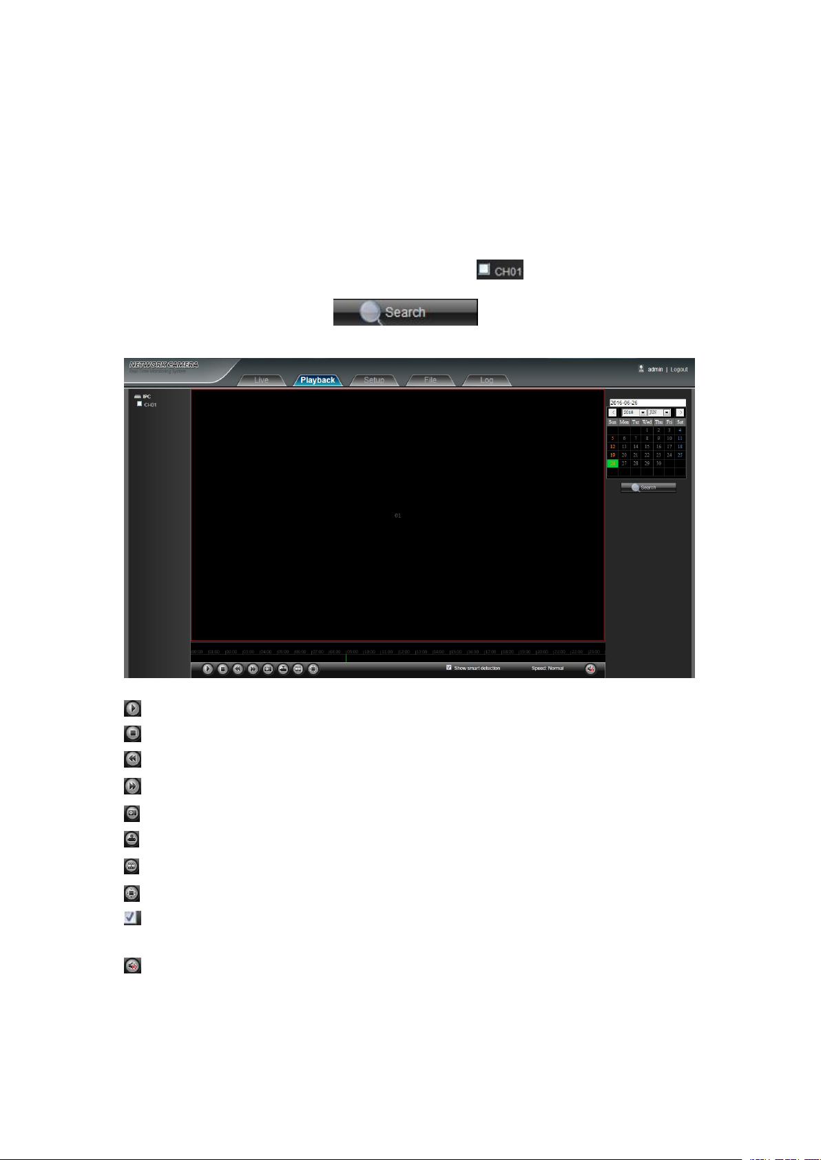
3. Playback
Click Playback enter into playback interface, click the icon , next select the date time of the
calling video in need, then click the icon , the record video will search automatically,
as shown in the follow figure:
Start: Start the current playback
Stop: Stop the current playback
Slow:Slow down the playback speed(1/2, 1/4, 1/8, 1/16 times optional)
Fast:Speed up the playback speed(2, 4, 8, 16 times optional)
Capture: Can be Capture in any playback channel
Backup:Can be backup video in any playback channel
Frame Play:Single frame to play
Full Screen: Playback video will display with full screen
Show smart detection: Display intelligent detection :when the video is to intelligentlt detect video,it can
display intelligent Detection rules and statistical result.
Voice: Adjust the volume of playback audio
Double-click the slider location, it will start to paly the video, or you can click the Start button to playback
video.
(Note: The device should support TF card storage to enable this function)

5
4. Setup
Note:the inserted TF card is for full function display interface, otherwise, it's for simple type interface.
Device Name: Edit the camera name
Device Type: Display the device type
Serial No. : Display the product serial No.
Master Version: Display the software version date
Hardware Version: Display the hardware version number
4.1 Device Info
IP Camera Device Info interface as shown in the follow figure:
6
Audio Source: Select the audio input mode, LineIn or MicIn selectable
Format: Switch to select the PAL and NTSC image scanning system
Device Time: Set and display the device current time
After complete all parameters setting, click Save and then it will take effect immediately.
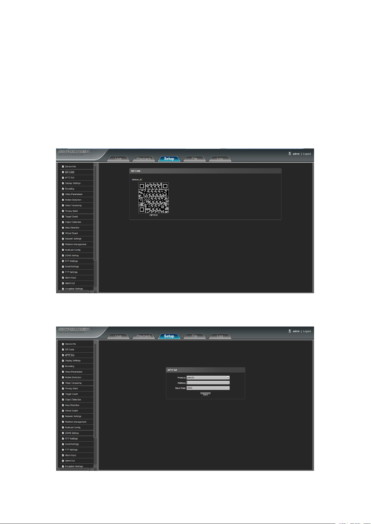
4.2 QR Code
Scan the QR code to login directly via mobilephone client, the IP camera QR code interface as shown in the
following figure. (Note: After enable the corresponding protocols in the platform management interface, then the
QR code icon will display. QR code support: Fseye. During the platform management interface, Device_ID
protocol should be matched with Fseye Client.)
4.3 ePTZ Setting
IP Camera ePTZ Set interface as shown in the follow figure:
7
Protocol: Support pelcoD and pelcoP protocol
Address: Support 0-255 address code adjustable
Baud Rate: Support diverse baud rate selectable
Operation Method: Connect analog high speed dome at the IP camera AB port, set the protocol and baud rate,
and control the high speed dome through IPC preview interface
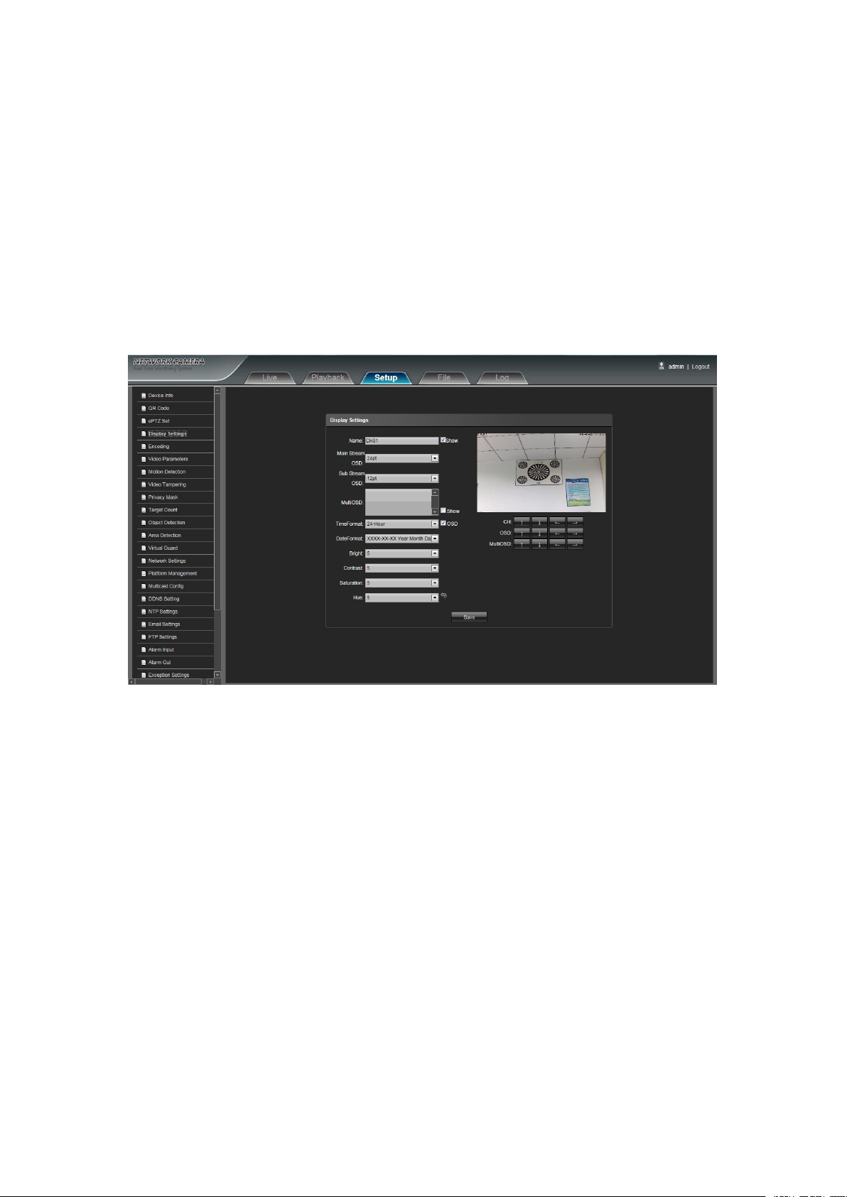
Name: Modify the appointed channel name
Main Stream OSD: Modify the appointed channel font of main stream OSD
Sub Stream OSD: Modify the appointed channel font of sub stream OSD
Multi OSD:Add multi user-defined OSD, it can be selected Show or not
Time Format: Select different time display mode for the appointed channel
Date Format: Select different date display mode for the appointed channel
Bright: Adjust the brightness for the appointed channel
Contrast: Adjust the contrast for the appointed channel
Saturation: Adjust the saturation for the appointed channel
Hue: Adjust the hue for the appointed channel
CH(Title Location): Set the channel title location for the appointed channel
OSD(Date Adjustment): Set the channel date location for the appointed channel
Multi OSD(Position adjustment): Multi-line OSD characters can be set up the corresponding location
Cyclotron Arrow: Restore the default parameters(Only for Bright, Contrast, Saturation and Hue)
After complete all parameters setting, click Save and then it will take effect immediately.
4.4 Display Settings
IP Camera Display Settings interface as shown in the follow figure.
After complete all parameters setting, click Save and then it will take effect immediately.

8
4.5 Encoding
Compress Type: Primary Stream(Normal)/ Sub Stream selectable
Stream: Include complex stream/ video stream two types
Resolution: The camera supports several relolution, will display here.
Frame Rate: Select different frame rate in the drop-down list, default is Full Frame
Video Encode: H.264/ MJPEG/H.264+ three kinds of video encode format
H264 Profile: There are MainProfile/ Baseline/ HighProfile three types optional
I frame Interval: Set the I frame interval time
Bitrate Type: Constant/ Variable selectable
Bitrate: Set different bitrate for different channels
IP Camera Encoding setting interface as shown in the follow figure:
After complete all parameters setting, click Save and then it will take effect immediately.

9
4.6 Video Parameters
Day&Night Mode: Outside Trigger/ Auto/ Color/ Black White four kinds of mode selectable. Non infrared IP
Switching Time: Day&Night switch delay time, 0-30s selectable, and default is 3s
Day-Ni-Threshold: 0-255 selectable, users can adjust it according to the need, default is 20
Ni-Day-Threshold: 0-255 selectable, users can adjust it according to the need, default is 35
Color Mode: Normal/ Bright/ Nature three options, default is Normal
Mirror: Close/ Horizonal Mirror/ Vertical Mirror/ 180 Rotation/90 Rotation/270 Rotation six options, default is
TWDR: Close/ Low/ Mid/ High four options, default is Close
3DNR: Close/ Low/ Mid/ Mid-High/ High five levels, default is Close
Sharpness: 0-255 selectable, default is 128
Defogging:Close/ Low/ Mid/ High four options,default is Close.
Exposure Control Mode: Auto/ Manual selectable, default is Auto
AGC: Low/ Mid-Low/ Mid/ Mid-High/ High selectable, default is Mid-High. The higher Auto Gain value, the
Shutter: Auto , manual: 1/30(25)-1/10000, the default is Auto shutter
Gamma: CURVE_1_6, CURVE_1_8, CURVE_2_0, CURVE_2_2 totally four modes, default is CURVE_2_0
Anti-Fliker: Close, 50hz, 60hz three types, the default is Close
Aperture: Iris, Manual/Auto selectable, default is Auto. Lens, Manual/Semiautomatic selectable(There is this
IP Camera Video Parameters setting interface as shown in the follow figure:
cameras default mode is Auto, and infrared IP cameras default mode is Outside Trigger. According to the IP
camera type and actual scene, user can select the Day&Night mode optional
Close
better sensitivity within low illumination, while the noise will be more obvious
option when it's equipped with electric lens),default is Semiautomatic
After complete all parameters setting, click Save, the settings will take effect immediately.

10
4.7 Motion Detection
Enable: Select whether to enable the Motion Detection function.
Arm Schedule: Set the alarm schedule from Monday to Sunday
Mask Set: Press and drag the left mouse button in the Mask Set preview interface, then draw the small check
Clear: Click Clear to clear the current detective areas
Sensitivity: The higher sensitivity, the more obvious motion detective effect
Email: Click Email. Once alarm triggers that it will send Email to appointed mailbox
Snap: Click Snap. Once alarm triggers that it will linkage camera to snapshot picture and store it in the TF card
Record: Click Record.Once alarm triggers that it will linkage camera to record video and restore it in the TF
Alarm Output: There is a active warner connected to the alarm output port. Once alarm triggers that it will
Enable PTZ: When motion detection triggers alarm, it will linkage the PTZ motion
Preset: When motion detection triggers alarm, it will linkage the presets
Snap Interval: Set the snapshot interval time
Snap Count: Set the snapshot image count for this time
IP Camera Motion Detection setting interface as shown in the follow figure:
optional to set the detective areas
card.
linkage embedded relay switch to make alarm output
After complete all parameters setting, click Save, the settings will take effect immediately.
11
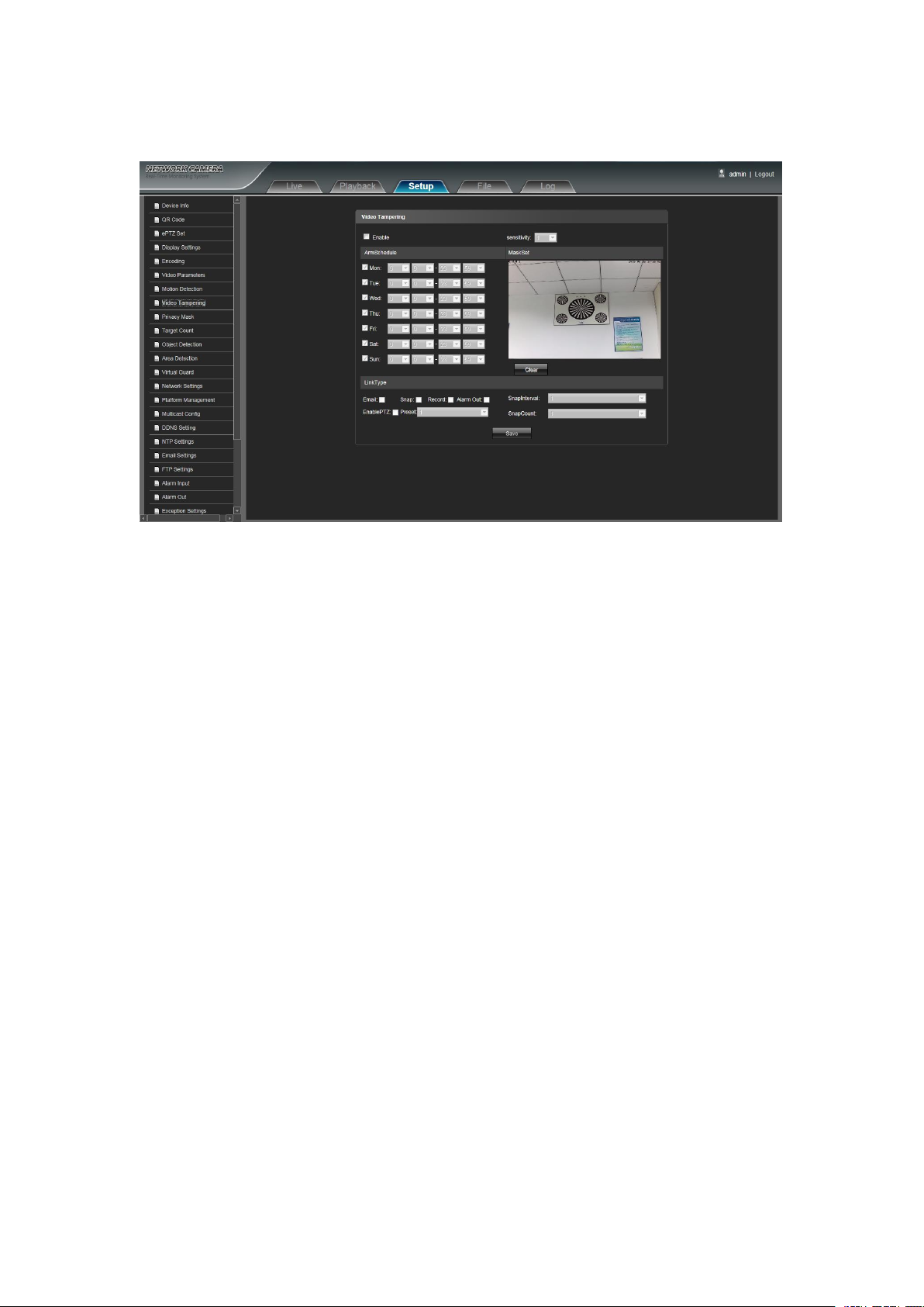
4.8 Video Tampering
Enable: Select whether to enable the Video Tampering function.
Arm Schedule: Set the alarm schedule from Monday to Sunday
Mask Set: Press and drag the left mouse button in the Mask Set preview interface, then draw the small check
Clear: Click Clear to clear the current detective areas
Sensitivity: The higher sensitivity, the more obvious motion detective effect
Email: Click Email. Once alarm triggers that it will send Email to appointed mailbox
Snap: Click Snap. Once alarm triggers that it will linkage camera to snapshot picture and store it in the TF card
Record: Click Record. Once alarm triggers that it will linkage camera to record video and restore it in the TF
Alarm Output: There is a active warner connected to the alarm output port. Once alarm triggers that it will
Enable PTZ: When motion detection triggers alarm, it will linkage the PTZ motion
Preset: When motion detection triggers alarm, it will linkage the presets
Snap Interval: Set the snapshot interval time
Snap Count: Set the snapshot image count for this time
IP Camera Video Tampering setting interface as shown in the follow figure:
optional to set the detective areas
card.
linkage embedded relay switch to make alarm output
After complete all parameters setting, click Save, the settings will take effect immediately.

12
4.9 Privacy Mask
Enable: Enable or disable the Privacy Mask function
Area Settings: Press and drag the left mouse button in the Area Settings preview interface, then draw the
Clear: Click Clear to delete the current mask area
IP Camera Privacy Mask setting interface as shown in the follow figure:
check optional to set the mask area
After complete all parameters setting, click Save and then the settings will take effect immediately.

13
4.10 Target Count
Enable: Enable or disable the Target Counting function
Arm Schedule: Arm schedul Can be set from Monday to Sunday
Mask Set: Press and drag the left mouse button to set the test line in the Area Settings preview interface, then
Clear: Click Clear to delete all the test lines
Test Line: To add new test lines (support max. 4 test lines), or set the parameter setting for the corresponding
Statistics: Set the test lines for targets passing through, there are A→B and B→A two statistical methods.
Flow Counter: Enable or disable the Flow Counter function
Interval: Set the counting time interval, when it is more than the time interval, the flow counter will reset and
Threshold: Set the upper limit value for counting, when it is more than the setting value, it will trigger alarm
Total Counter: Enable or disable the Total Counter function
Time: Set the effective time period for the day’s total counter
Alarm Threshold: Set the upper limit value for the day’s total flow, when it is more than the setting value, it
Target Percent: Set the min. area percent for the effective counting targets, once the area of targets passing
Email: Click Email. Once alarm triggers that it will send Email to appointed mailbox
Snap: Click Snap. Once alarm triggers that it will linkage camera to snapshot picture and store it in the TF card
Record: Click Record. Once alarm triggers that it will linkage camera to record video and store it in theTF
Alarm Output: There is a active warner connected to the alarm output port. Once alarm triggers that it will
Enable PTZ: When motion detection triggers alarm, it will linkage the PTZ motion
IP Camera Target Count setting interface as shown in the follow figure:
click the right button to complete the setting, and the targets passing through the line will be counted
test line optional
enter into next counting period automatically
function automatically
will trigger alarm function automatically
through the test line are smaller than the setting value, it will be invalid without be counted
card.
linkage embedded relay switch to make alarm output

14
Preset: When motion detection triggers alarm, it will linkage the presets
Snap Interval: Set the snapshot interval time
Snap Count: Set the snapshot image count for this time
After complete all parameters setting, click Save and then the settings will take effect immediately.
Enable: Enable or disable the Object Detection function
Arm Schedule: Can be set the arm schedule from Monday to Sunday
Mask Set:Press and drag the left mouse button to set the detect zone in the Area Settings preview interface,
Clear: Click Clear to delete all the detect zones.
Detect Zone: To add new detect zone (support max. 4 detect zones), can be set the parameter setting for the
Detect Type: Set the object detect type, there are three detect types, both of them will trigger alarm. Item lost
Target Percent: Set the min. area percent for the object, the area of object is smaller than the setting value, it
Time: Set the upper limit value for the item lost and item left, when it is more than the setting value, it will
Email: Click Email. Once alarm triggers that it will send Email to appointed mailbox
Snap: Click Snap. Once alarm triggers that it will linkage camera to snapshot picture and store it in the TF card
Record: Click Record. Once alarm triggers that it will linkage camera to record video and store it in the TF
Alarm Output: There is a active warner connected to the alarm output port. Once alarm triggers that it will
4.11 Object Detection
IP Camera Object Detection setting interface as shown in the follow figure:
then click the right key to complete the setting, and the objects of this area will be monitored and detected
corresponding detect zone optional
refers to once the object lost in the detect zone, the camera will trigger alarm, Item left refers to once the new
added object detected in the detect zone, the camera will trigger alarm.Item lost or left refers to both of object lost
and adding,the camera will trigger alarm.
will be invalid
trigger alarm function automatically
card.
linkage embedded relay switch to make alarm output

15
Enable PTZ: When motion detection triggers alarm, it will linkage the PTZ motion
Preset: When motion detection triggers alarm, it will linkage the presets
Snap Interval: Set the snapshot interval time
Snap Count: Set the snapshot image count for this time
After complete all parameters setting, click Save and then the settings will take effect immediately.
Enable: Enable or disable the Area Detection function
Arm Schedule: Can be set the arm schedule from Monday to Sunday
Mask Set: Press and drag the left mouse button to set the detect zone in the Area Settings preview interface,
Clear: Click Clear to delete all the detect zones.
Detect Zone: To add new detect zone (support max. 4 detect zones), can be set the parameter setting for the
Detect Type: Set the target detect type, there are four detect types, all of them will trigger alarm. Target enter
Target Percent: Set the min. area percent for the object, the area of object is smaller than the setting value, it
Time: Set the upper limit value for the item lost and item abandon, when it is more than the setting value, it will
Email: Click Email. Once alarm triggers that it will send Email to appointed mailbox
Snap: Click Snap. Once alarm triggers that it will linkage camera to snapshot picture and store it in the TF card
Record: Click Record. Once alarm triggers that it will linkage camera to record video and store it in the TF
4.12 Area Detection
IP Camera Area Detection setting interface as shown in the follow figure:
then click the right key to complete the setting, and the objects of this area will be monitored and detected
corresponding detect zone optional
refers to once the target enter into the detect zone, the camera will trigger alarm, Target leave refers to the target
go out the detect zone, the camera will trigger alarm, Target enter or leave refers to both of them happen, the
camera will trigger alarm .Target Wander refers to the target enters into and goes out the detect zone for many
times, the camera will trigger alarm
will be invalid
trigger alarm function automatically

16
card.
Alarm Output: There is a active warner connected to the alarm output port. Once alarm triggers that it will
Enable PTZ: When motion detection triggers alarm, it will linkage the PTZ motion
Preset: When motion detection triggers alarm, it will linkage the presets
Snap Interval: Set the snapshot interval time
Snap Count: Set the snapshot image count for this time
Enable: Enable or disable the Virtual Guard function
Arm Schedule: Can be set the arm schedule from Monday to Sunday
Mask Set:Press and drag the left mouse button to set the guard line in the Area Settings preview interface, then
Clear: Click Clear to delete all the detect zones.
Swap AB:Click "swap AB" to exchange position between A and B
Detect Zone: To add new guard line (support max. 4 guard lines), can be set the parameter setting for the
Statistics: Set the guard lines to trigger alarm. A→B refers to the targets pass through the guard line from A
Target Percent: Set the min. area percent for the object, the area of target passing through the guard line is
Email: Click Email. Once alarm triggers that it will send Email to appointed mailbox
Snap: Click Snap. Once alarm triggers that it will linkage camera to snapshot picture and store it in the TF card
Record: Click Record. Once alarm triggers that it will linkage camera to record video and store it in the TF
linkage embedded relay switch to make alarm output
After complete all parameters setting, click Save and then the settings will take effect immediately.
4.13 Virtual Guard
IP Camera Virtual Guard setting interface as shown in the follow figure:
click the right key to complete the setting, and the target passing through the guard line will trigger alarm
corresponding guard lines optional
area to B area and trigger alarm. A←→B refers to the targets pass through the guard line from A area to B area or
from B area to A area, both of them will trigger alarm.
smaller than the setting value, it will be invalid without triggering alarm
card.

17
Alarm Output: There is a active warner connected to the alarm output port. Once alarm triggers that it will
linkage embedded relay switch to make alarm output
Enable PTZ: When motion detection triggers alarm, it will linkage the PTZ motion
Preset: When motion detection triggers alarm, it will linkage the presets
Snap Interval: Set the snapshot interval time
Snap Count: Set the snapshot image count for this time
IPV4: IP protocol version No. is 4
IPV6: IP protocol version No. is 6, the feature is not optional at present
Static IP: The device IP address is permanent
DHCP: Enable DHCP, then IP camera will get the IP address from router automatically
IP Address: Input the corresponding numbers to change the IP address
Subnet Mask: Input the corresponding IP subnet mask
Gateway: Input the corresponding gateway address
DNS 1: DNS server IP address
DNS2: DNS server second IP address
HTTP Port: Input the corresponding port ( Default is 80)
HTTPS Port: Input the corresponding port ( Default is 443)
RTSP Port: Use domain name to access and login device need mapping RTSP, default port is 554
RTMP Port: Use domain name to access and login device need mapping RTMP, default port is 1935
Enable UPnp: Enable UPnp, then device port and HTTP port will be mapped to the router automatically
Device Port: Input the corresponding device port(Default is 5050)
Enable PPPoe: Click to enable PPPOE
User Name: Input the user name
Password: Input the password
Confirm pwd: Input the password again to confirm it
PPPoe IP: Input device dynamic address
After complete all parameters setting, click Save and then the settings will take effect immediately.
4.14 Network Settings
IP Camera Network Settings interface as shown in the follow figure:
After complete all parameters setting, click Save, then the settings will take effect immediately.

18
4.15 Platform Management
Network High Speed Dome Platform Management interface as shown in the follow figure:
User can open, close, edit and delete the protocol in the Management Platform interface.
4.16 Multicast Config
IP Camera Multicast Config interface as shown in the follow figure:
Multicast Config is in disable status by default. While click Enable Multicast, users can set the primary
stream, sub stream, audio IP address, port, and TTL.

19
4.17 DDNS Setting
Enable DDNS: Click to determine whether to use Dynamic Domain Name Server
Server Type: Select DDNS server type (There are Dyndns/ PeanutHull/ NO-IP/ 3322/ DnsDynamic five types
selectable)
Server Name: Input server name, for example, members.3322.org
Port: Input port No.(default is 80)
Username: Input user name
Password: Input password
Confirm pwd: Input the password again to confirm it
Domain: Input the standby domain
DDNS is implemented through a dynamic domain resolution server. It requires a PC running in the
server with fixed IP address on the Internet. IP Camera network setting interface as below figure:
After complete all parameters setting, click Save, then the settings will take effect immediately.

20
4.18 NTP Settings
Enable NTP: Enable or disable NTP function
Server Address: Input NTP server IP address
NTP Port: SNTP only supports TCP transmission, default port is 123
Adjust Time Interval: Input the interval time
Select Time Zone: Different area time format selectable
GMT: Adjust the time to make it more exact
IP Camera NTP Settings interface as shown in the follow figure:
After complete all parameters setting, click Save, then the settings will take effect immediately.

21
4.19 Email Settings
(sent)Email Address: Input the address of the outbox
Password: Input the the password of the outbox
Confirm pwd: Input the password again to confirm it
(send)SMTP Server: Input the smtp server address of the outbox
SMTP Port: Input the smtp server port of the outbox
Sending Interval: Input the sending interval time. There are 25S/ 35S/ 45S/ 55S four options
Receiver: Input the mail receiver name
Email Address: Input the address of the inbox
IP Camera Email Settings interface as shown in the follow figure:
After complete all parameters setting, click Save and then the settings will take effect immediately.
22
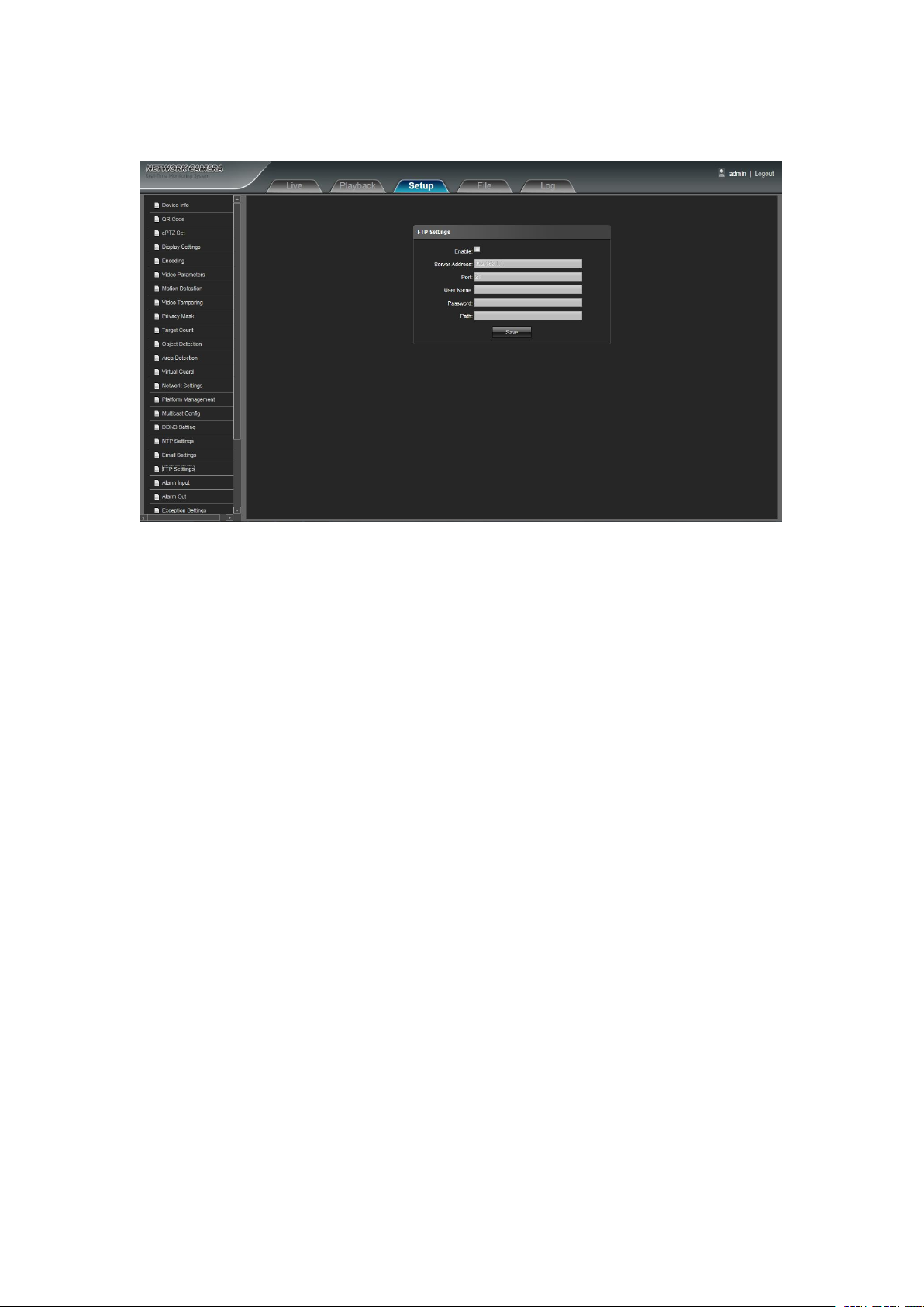
4.20 FTP Settings
Enable: Click Enable to enable or disable FTP function
Server Address: Input the server address required to upload
Port: Input the server port, default is 21
User Name: Input the user name required to upload
Password: Input the password required to upload
Path: Input the file path required to upload
IP Camera FTP Settings interface as shown in the follow figure:
After complete all parameters setting, click Save and then the settings will take effect immediately.
23
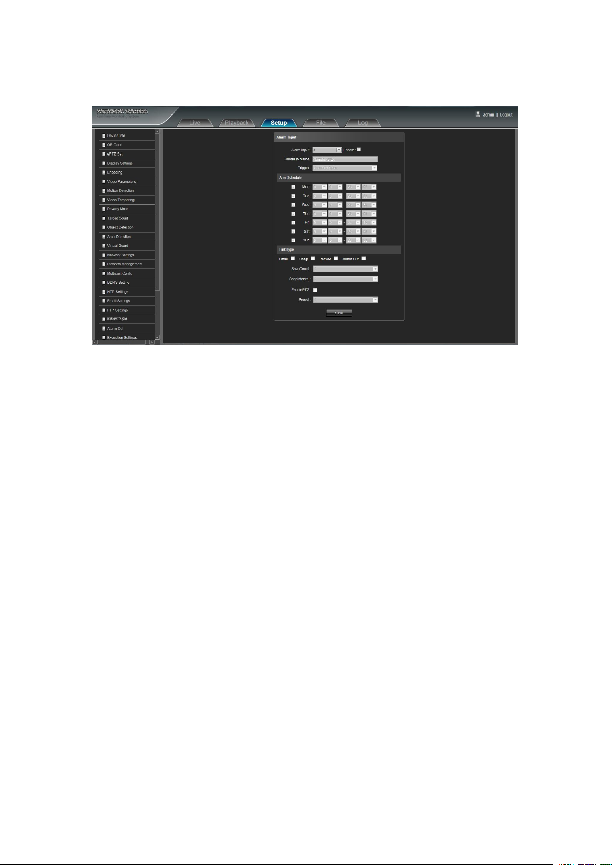
4.21 Alarm Input
Alarm Input: Select the alarm input port, there are 1/ 2 optional. Then click Handle can implement follow
Alarm In Name: Input alarm input name
Trigger: Select the alarm status: Normally Open/ Normally Close
Arm Schedule: Alarm schedule can be set from Monday to Sunday
Email: Click Email. Once alarm triggers that it will send Email to appointed mailbox
Snap: Click Snap. Once alarm triggers that it will snapshot current image picture
Record: Click Record. Once alarm triggers that it will record video automatically
Alarm Output: Click Alarm Output. There is a active warner connected to the alarm output port. Once alarm
Snap Count: Set the snapshot image count for this time
Snap Interval: Set the snapshot interval time
Enable PTZ: Click Enable PTZ. When alarm input riggers alarm, it will linkage the PTZ motion
Preset: Select the linkage preset point from 1 to 8 optional
IP Camera Alarm Input setting interface as shown in the follow figure:
parameters settings
triggers that it will linkage embedded relay switch to make alarm output
After complete all parameters setting, click Save, the settings will take effect immediately.

24
4.22 Alarm Out
Output Relay Status: Normally Open/ Normally Close selectable
Output Delay: Select the alarm output delay time(when alarm trigger is over, it will output corresponding
Exception Type: There are Network Broken/ IP Address Conflict/ Illegal Access/ three exception types
Record: Click Record, it will linkage to record video as any exception type triggers
Alarm Output: Click Alarm Output, it will Linkage other alarm devices as any exception type triggers
IP Camera Alarm Out setting interface as shown in the follow figure:
alarm delay time)
After complete all parameters setting, click Save and the settings will take effect immediately.
4.23 Exception Settings
IP Camera Exception Settings interface as shown in the follow figure:
selectable
After complete all parameters setting, click Save and then the settings will take effect immediately.
25
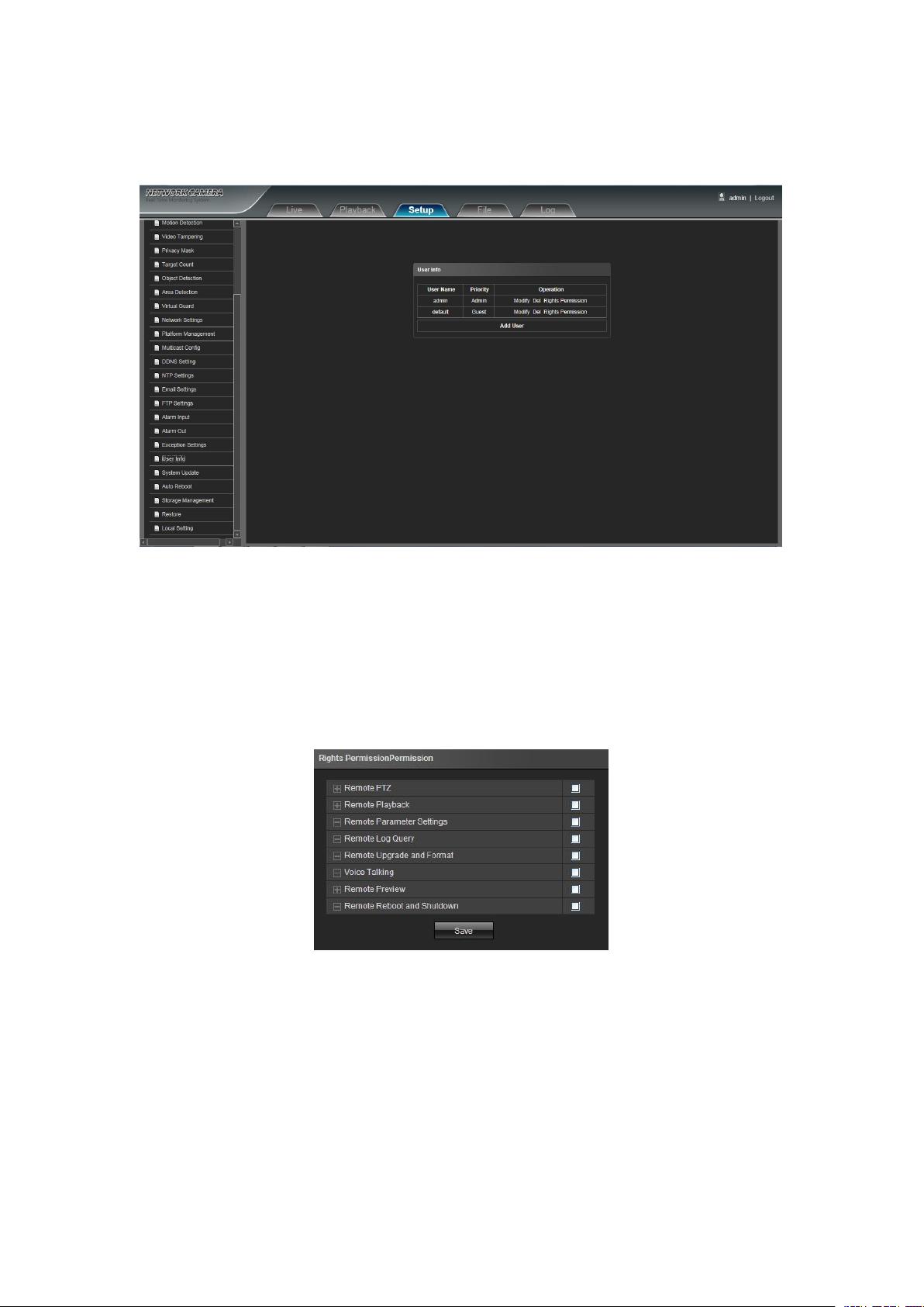
4.24 User Info
Modify: Administrator account can modify login password, while general users can modify user type including
Del: Delete the new user
Rights Permission: Set rights permission assignment for new user
Add User: Add a new user in need
IP Camera User Info setting interface as below figure, admin is the administrator (default), default indicates
general users.
Guest, Operator two options, and setup different permission assignment in the Rights Permission settings
Start up and login permission is accord with default user permission(default), as shown in the follow figure:
After complete all parameters setting, click Save and then the seetings will take effect immediately.
26
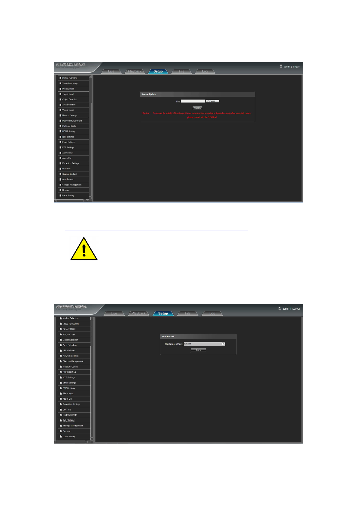
4.25 System Update
File: Click Browse to find and select the upgrade kit, then click Update.
Non-technician should not try to operate system upgrade, do
not cut off the power during upgrade process.
IP Camera System Update setting interface as shown in the follow figure:
4.26 Auto Reboot
IP Camera Auto Reboot setting interface as below figure. Select Maintenance Mode, there are Disable/
Every Day/ Every Week/ Once four modes optional, then IPC will reboot as appointed mode.
27
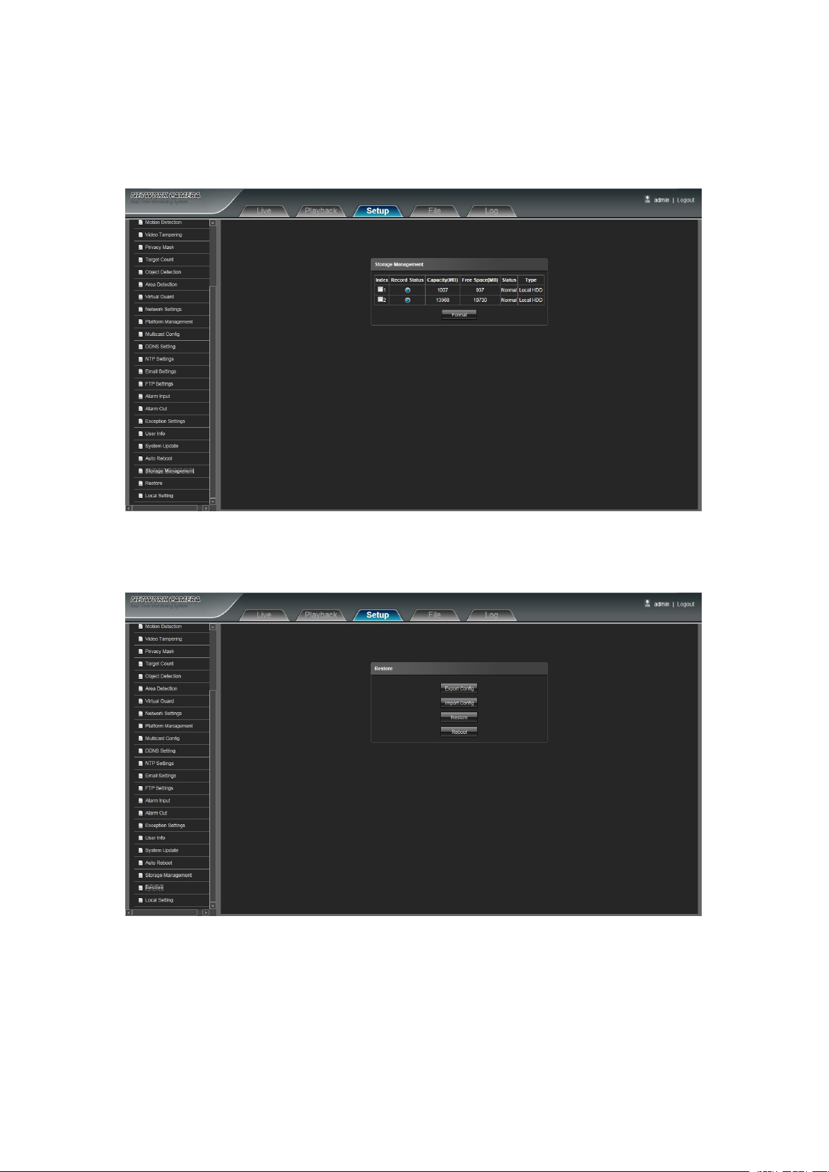
4.27 Storage Management
Export: Export all configurations to PC or USB
Import Config:Import selected configuration to the system
Restore: Restore the factory settings
Reboot: Reboot the device
IP Camera Storage Management setting interface as below figure, you can check current HDD
Capacity(MB)/ Free Spare (MB)/ Status, and format HDD. As shown in the follow figure:
Note: Please turn off the power supply, before you insert or take out the TF card.
4.28 Restore
IP Camera Restore setting interface as shown in the follow figure:

28
4.29 Local Setting
Window Mode: Set the preview window mode(Full/ 4:3/ 16:9/ Original Image optional)
Preview Capture: Select and modify the preview capture file storage path
Playback Capture: Select and modify the video record capture file storage path
File Capture: Select and modify the file management capture file storage path
Back Up: Select and modify video record backup file storage path
Rec Capture: Select and modify the preview interface video record file storage path
Record File Type: Only AVI format one option for default
Live View Mode: Realtime/ Smoothway two types selectable, the value of them can be adjustable
IP Camera Local Setting interface as shown in the follow figure:
After complete all parameters settings, click Save and then the settings will take effect immediately.

29
5. File Management
Note:the inserted TF card is for full function display interface, otherwise, it's for simple type interface.
5.1 Search
Input the concrete time, and click the button, the lower part displays searched images and videos
(double click to display files)
Note: It can modify video or image storage path, and later chapter will make a brief instruction (more details
please refer to Setup Local Setting)
5.2 Playback Capture
To review video record playback capture files, search and double click the image files directly.

30
5.3 Backup
Start: Click button to play the backup video image file
Stop: Click button to stop the play
Slow: Click button to slow play the backup video image file
Fast: Click button to fast play the backup video image file
Frame: Click button to play the backup video image file by frame
Capture: Click button to snap the backup video image during display
Voice: Click button to select turn on/ off the voice during backup video image display
To review playback video files, search and double click the video files directly.
5.4 Linkage Capture
To review motion detection, tampering alarm, alarm output, ect. alarm linkage capture files, search and
double click the image files directly.
5.5 Preview Capture
To review preview capture files, search and double click the image files directly.
5.6 File Capture
To review capture files in file management, search and double click the image files directly.
5.7 Preview Videos
To review preview interface video record files, search and double click the video files directly.
5.8 Backup Video Play

31
6. Log
Main Type: Select the log type to check. There are Alarm/ Exception Settings/ Operation / Setup optional, or
Start Time/ End Time: Select the time quantum of log to check
Page Num:Select the log number of each page to display on the interface
Click Search on the Log interface, check device log according to the video type and date time, as shown in
the below figure:
click All to check all types of them
After finishing all settings above, click Search and then the log information will display on the left blank area
7. Exit
Click Logout to log out, as shown in the follow figure:
 Loading...