

IVS S9353 Installation Manual

350Z
D748_746_744_Quick_V1.1
Installation Guide
Intelligent Video Surveillance
GUI Display with USB Mouse Control
Please read instructions thoroughly before operation and retain it for future reference.
For the actual display & operation, please refer to your DVR in hand.
IMPORTANT SAFEGUARD
CAUTION
RISK OF ELECTRIC SHOCK
CAUTION:
To reduce the risk of electric shock, do not expose this apparatus to rain or moisture. Only operate this apparatus
from the type of power source indicated on the label. The company shall not be liable for any damages arising out
of any improper use, even if we have been advised of the possibility of such damages.
The lightning flash with arrowhead symbol, within an equilateral triangle, is intended to alert the user to the presence of
uninsulated “dangerous voltage” within the product’s enclosure that may be of sufficient magnitude to constitute a risk of electric
shock to persons.
This exclamation point within an equilateral triangle is intended to alert the user to the presence of important operating and
maintenance (servicing) instructions in the literature accompanying the appliance.
All lead-free products offered by the company comply with the requirements of the European law on the Restriction of Hazardous
Substances (RoHS) directive, which means our manufacture processes and products are strictly “lead-free” and without the
hazardous substances cited in the directive.
The crossed-out wheeled bin mark symbolizes that within the European Union the product must be collected separately at the
product end-of-life. This applies to your product and any peripherals marked with this symbol. Do not dispose of these products as
unsorted municipal waste. Contact your local dealer for procedures for recycling this equipment.
This apparatus is manufactured to comply with the radio interference requirements.
Trademark Acknowledgements
and (EagleEyes) - The trademark application is filed and under process in the U.S. and other countries.
iPhone® is the registered trademark of Apple Inc., and Apple holds the intelligential property rights to the iPhone content.
Disclaimer
The information in this manual was current when released. We reserve the right to revise or remove any content in this manual at any time. We
do not warrant or assume any legal liability or responsibility for the accuracy, completeness, or usefulness of this manual. For the actual display
& operation, please refer to your DVR in hand. The content of this manual is subject to change without notice.
Grounding
This is a Safety Class 1 Product (provided with a protective earthing ground incorporated in the power cord). The mains plug shall only be
inserted in a socket outlet provided with a protective earth contact. Any interruption of the protective conductor inside or outside of the instrument
is likely to make the instrument dangerous. Intentional interruption is prohibited.
Water & Moisture
Do not expose this product to dripping or splashing and that no objects filled with liquids, such as vases, shall be placed on the product.
MPEG4 Licensing
THIS PRODUCT IS LICENSED UNDER THE MPEG-4 VISUAL PATENT PORTFOLIO LICENSE FOR THE PERSONAL AND
NON-COMMERCIAL USE OF A CONSUMER FOR (i) ENCODING VIDEO IN COMPLIANCE WITH THE MPEG-4 VISUAL STANDARD
(“MPEG-4 VIDEO”) AND/OR (ii) DECODING MPEG-4 VIDEO THAT WAS ENCODED BY A CONSUMER ENGAGED IN A PERSONAL AND
NON-COMMERCIAL ACTIVITY AND/OR WAS OBTAINED FROM A VIDEO PROVIDER LICENSED BY MPEG LA TO PROVIDE MPEG-4
VIDEO. NO LICENSE IS GRANTED OR SHALL BE IMPLIED FOR ANY OTHER USE. ADDITIONAL INFORMATION INCLUDING THAT
RELATING TO PROMOTIONAL INTERNAL AND COMMERCIAL USES AND LICENSING MAY BE OBTAINED FROM MPEG LA, LLC. SEE
HTTP://WWW.MPEGLA.COM.
GPL Licensing
This product contains codes which are developed by Third-Party-Companies and which are subject to the GNU General
Public License (“GPL”) or the GNU Lesser Public License (“LGPL”).
The GPL Code used in this product is released without warranty and is subject to the copyright of the corresponding
author.
Further source codes which are subject to the GPL-licenses are available upon request.
We are pleased to provide our modifications to the Linux Kernel, as well as a few new commands, and some tools to get
you into the code. The codes are provided on the FTP site, and please download them from the following site or you
can refer to your distributor:
ftp://ftp.dvrtw.com.tw/GPL/AV074/

TABLE OF CONTENTS
1. PRODUCT OVERVIEW............................................................................................................ 1
2. CONNECTION AND SETUP.................................................................................................... 2
2.1 Prerequisites....................................................................................................................................................2
2.2 SATA HDD Installation .....................................................................................................................................2
2.3 Installing DCCS Camera..................................................................................................................................3
2.4 Connecting DCCS Camera..............................................................................................................................3
2.5 DVR Power On ................................................................................................................................................4
2.6 Date and Time Setting .....................................................................................................................................4
2.7 Clear Hard Disk ...............................................................................................................................................4
2.8 Password Setting.............................................................................................................................................5
2.9 Examining Signal Transmission.......................................................................................................................5
2.10 Configuring DCCS Camera............................................................................................................................6
2.10.1 For a PTZ camera................................................................................................................................6
2.10.2 For a zoom lens control camera ..........................................................................................................6
3. GUI DISPLAY WITH USB MOUSE CONTROL........................................................................ 7
3.1 Connect USB Mouse .......................................................................................................................................7
3.2 Quick Menu Bar ...............................................................................................................................................7
3.3 Main Menu .......................................................................................................................................................8
Main Menu Structure ......................................................................................................................................8
4. FRONT AND REAR PANELS ................................................................................................ 10
4.1 Front Panel ....................................................................................................................................................10
4.2 Rear Panel..................................................................................................................................................... 11
5. BASIC OPERATION............................................................................................................... 12
5.1 Live Page.......................................................................................................................................................12
5.2 Record Icon ...................................................................................................................................................12
5.3 Playback ........................................................................................................................................................12
Playback Control ..........................................................................................................................................13
Event Search ................................................................................................................................................13
Audio Playback.............................................................................................................................................13
5.4 User Level Switch ..........................................................................................................................................13
5.5 Video Output Switch ......................................................................................................................................14
APPENDIX 1. SET IPHONE PUSH NOTIFICATION.................................................................. 15
A1.1 Prerequisite .................................................................................................................................................15
A1.2 Set iPhone...................................................................................................................................................15
A1.2.1 Program Download............................................................................................................................15
A1.2.2 Program Setup ..................................................................................................................................16
A1.2.3 Push Notification On..........................................................................................................................17
APPENDIX 2. SET FLOW COUNTING / VIRTUAL FENCE / ONE-WAY PASS ........................ 18
A2.1 IVS APPLICATION ......................................................................................................................................19
A2.1.1 FLOW COUNTING............................................................................................................................19
A2.1.2 VIRTUAL FENCE and ONE WAY PASS............................................................................................20
A2.2 IVS STATISTICS .........................................................................................................................................21
1
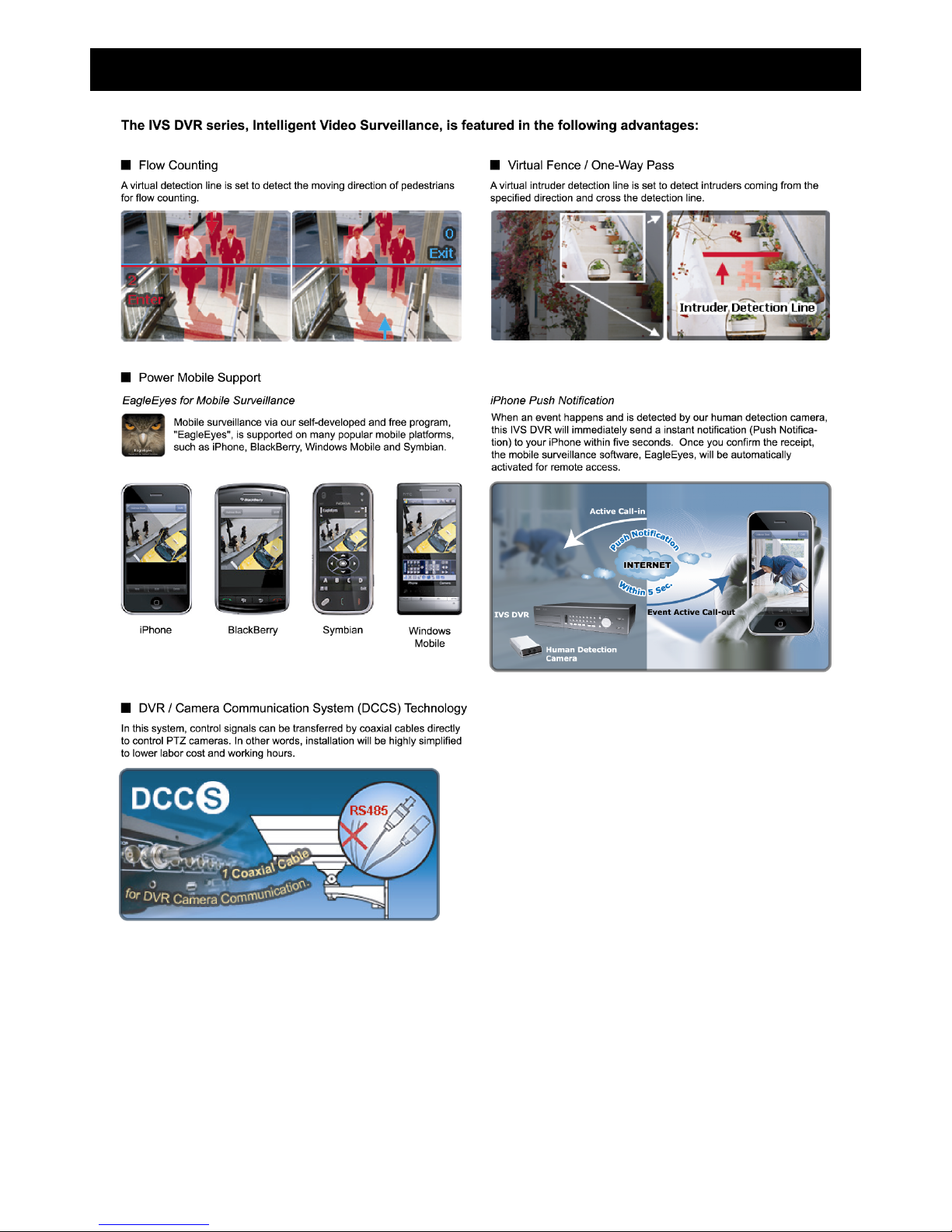
1. PRODUCT OVERVIEW
2
2. CONNECTION AND SETUP
Before the DVR is powered on, make sure you have installed a hard disk, connected at least one camera and a
monitor. For details, please refer to the following sections.
Note: The DVR is designed to automatically detect the video system of the connected cameras (NTSC or
PAL). To make sure the system detection is correct, please check if the cameras are connected to
the DVR and power-supplied before the DVR is powered on.
Note: The connection and setup described below are for DCCS devices only. For details about connecting
cameras other than DCCS ones, please refer to the DVR user manual.
2.1 Prerequisites
Make sure your cameras support the DCCS function. For details, please check with your distributor or
installer.
To ensure the signal transmission, the recommended distance between this DVR and cameras should not
exceed 200 meters by using 3C2V coaxial cables (112 braids).
However, different materials used in 3C2V coaxial cables with different connection distance may cause some
effects for the availability and fluency of signal transmission.
Therefore, please do the DCCS test as instructed in “2.9 Examining Signal Transmission” at page 5 when the
connection is completed to ensure this system can work normally.
It’s not allowed to use a signal booster or modem to amplify signals and extend the connection distance.
The DCCS function doesn’t support the channel which is looped from a DCCS camera connected to the same
DCCS DVR or to other DCCS DVR.
2.2 SATA HDD Installation
A SATA HDD must be installed before the DVR is powered on.
Note: It’s recommended to clear all data in the hard disk when the DVR is powered on and the date &
time are set correctly to ensure the recorded data are not mixed with other data previously saved
in the same hard disk. For details, please refer to “2.7 Clear Hard Disk” at page 4.
For 16CH & 8CH Models
Step1: Loose the screws on the upper cover and open the upper cover of the DVR.
Note: The DVR cover is made of metal. Please be careful with its edge when you remove the cover.
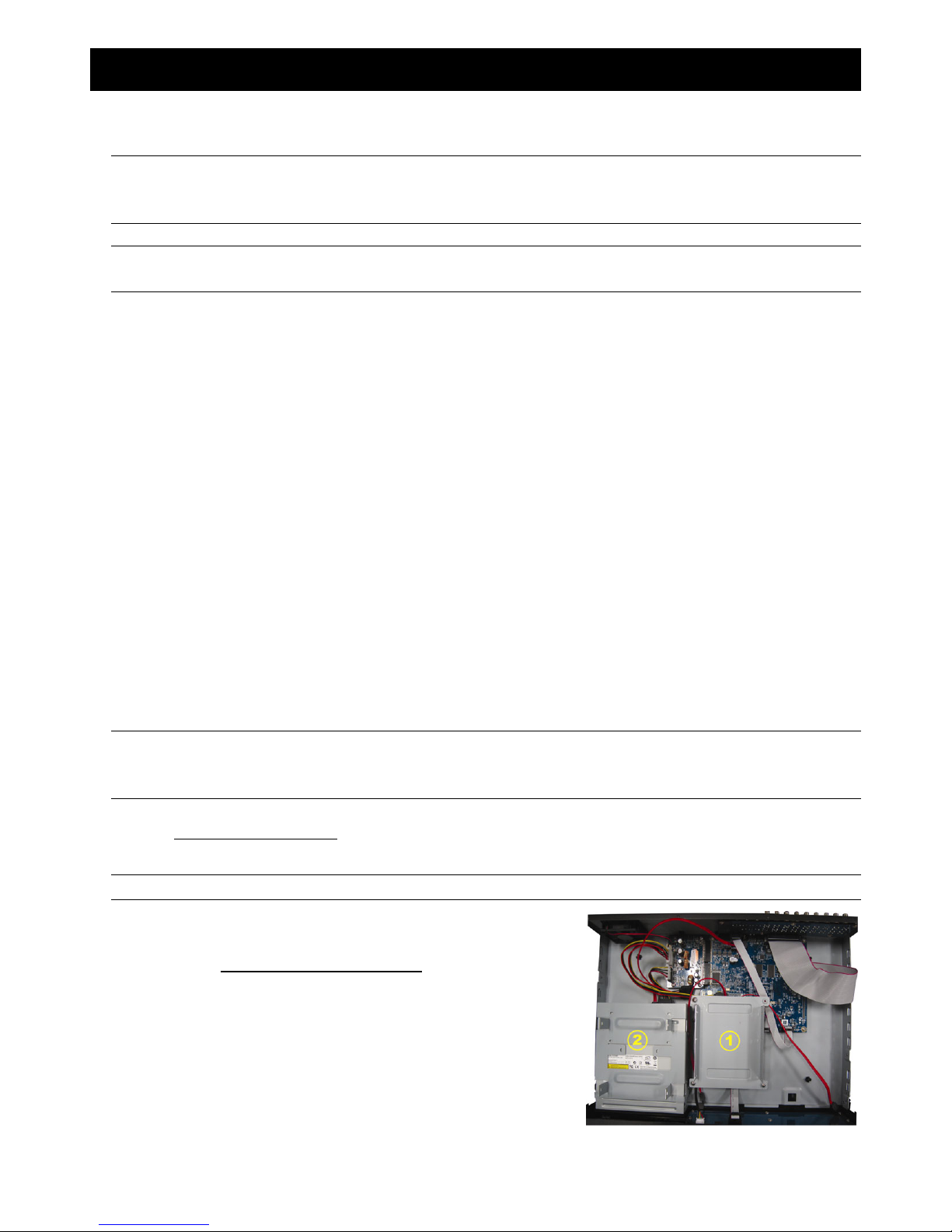
Step2: There are two HDD brackets for this DVR as indicated on
the right picture.
2-1 To install on the first bracket
Remove the bracket, and align the screw holes of the
bracket with the HDD’s screw holes. Make sure the
PCB side of the HDD is facing up.
Fasten the HDD to the bracket, and connect the power
connector and data bus connector to the HDD. Then,
replace the bracket to DVR.

3
2-2 To install on the second bracket
Connect the power connector and data bus connector
to the HDD.
When connecting the power cable, make sure the cable
is passed through the power cable of DVD writer. This is
to prevent the HDD power cable from interfering with
the fan spinning.
Align the screw holes of the bracket with the HDD’s
screw holes. Make sure the PCB side of the HDD is
facing up. Then, fasten the HDD to the bracket.
Step3: Close the upper cover of the DVR, and fasten all the screws you loosened in Step1.
For 4CH Model
Step1: Remove the screws on the top cover of DVR, and remove the top cover.
Step2: Remove the HDD bracket. Then, with the PCB side facing up, connect the compatible HDD to the power
connector and data bus connector.
Step3: Put the compatible HDD in the bracket, and fasten it with the supplied screws, two for each side.
Step4: Replace the bracket back to the DVR.
Step5: Replace the top cover and fasten the screws you loosened in Step1.
2.3 Installing DCCS Camera
Install the camera on the wall or ceiling based on your installation environment and camera type. For installation
details, please refer to the user manual of your camera.
Note: The distance between the camera and DVR needs to be within 200 meters for DCCS control to take
effects. For details, please refer to “2.1 Prerequisites” at page 2.
2.4 Connecting DCCS Camera
The cameras must be connected and power-supplied before the DVR is powered on. Connect the camera with
the indicated power supply. Then, connect the camera video output to the DVR video input port with a coaxial
cable or RCA cable with BNC connectors.
1) Video cable connection
Connect the camera video output to the DVR video input port with a coaxial cable or RCA cable with BNC
connector.
2) Power connection
Connect the camera with indicated power supply and make sure it’s power-supplied.
4
2.5 DVR Power On
This device should be operated only with the type of power source indicated on the manufacturer’s label. Connect
the indicated AC power cord to the power adapter, and plug into an electrical outlet. The power LED will be on.
Note: Before the DVR is powered on, make sure (1) the cameras are connected and power-supplied for
the detection of the camera video system to be correct, and (2) a monitor (either LCD or CRT
monitor) is connected to the DVR for correct video output detection.
Note: To ensure that your DVR works constantly and properly, it's recommended to use an UPS,
Uninterruptible Power Supply (Optional), for continuously operation.
2.6 Date and Time Setting
Before operating your DVR, please set the date and time on your DVR FIRST.
Note: Please DO NOT change the date or time of your DVR after the recording function is activated.
Otherwise, the recorded data will be disordered and you will not be able to find the recorded file
to backup by time search. If users change the date or time accidentally when the recording
function is activated, it’s recommended to clear all HDD data, and start recording again.
Note: For the first time to use the DVR, please power it on for at least 48 hours continuously after the
date & time is set correctly. It helps to prevent DVR time from resetting after the disconnecting of
DVR power. If the DVR time resets after the disconnecting of DVR power, for example, caused by
a power outage, the battery might run out and please replace the battery as described in
“APPENDIX 6” in the DVR user manual.
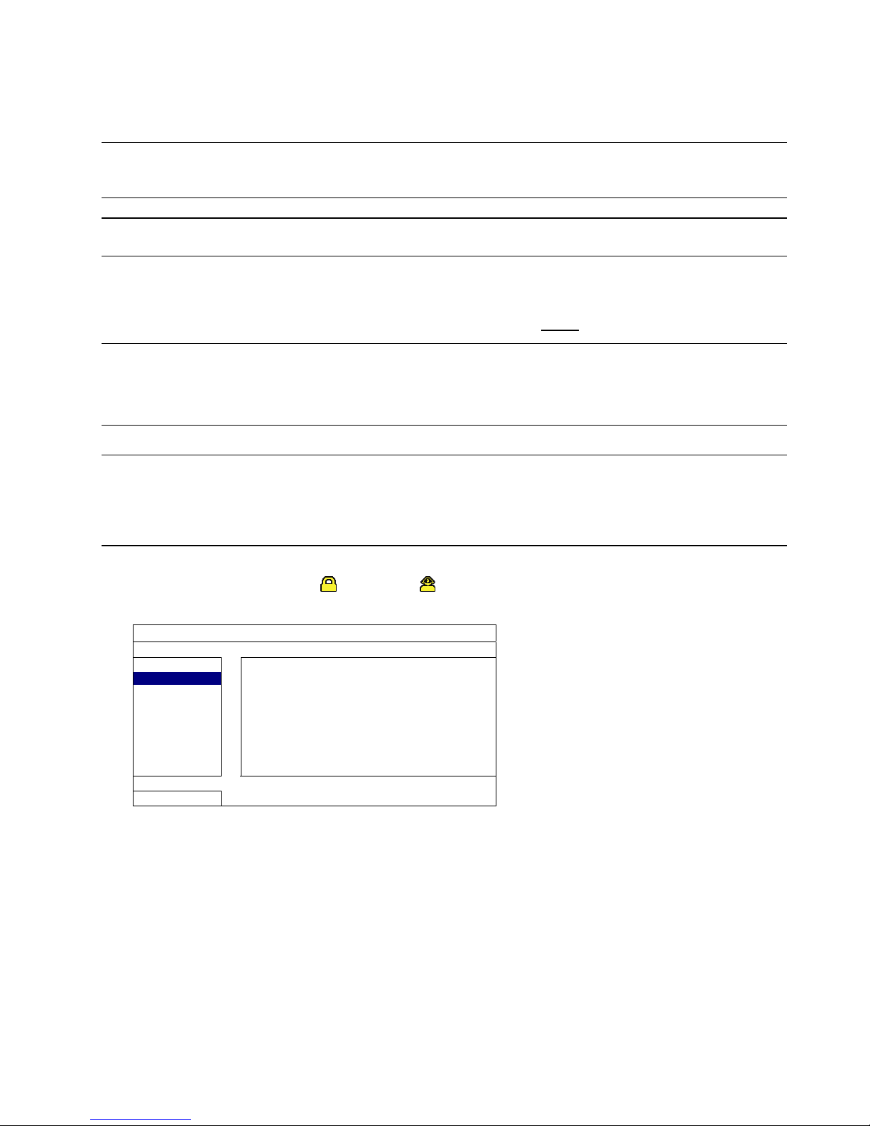
Right-click to enter the DVR password with the password keypad. The default administrator password is 0000.
The status will be changed from (key lock) to (administrator). Then, right-click to show the main menu,
and select “QUICK START” “TIME SETUP” to set the date & time.
QUICK START
GENERAL
DATE 2009 / NOV / 17
TIME SETUP
TIME 15 : 35 : 53
EXIT
2.7 Clear Hard Disk
It’s recommended to clear all data in the hard disk for the first time to user this DVR to ensure the recorded data
are not mixed with other data previously saved in the same hard disk.
Right-click to show the main menu, and select “SYSTEM” “SYSTEM INFO” “CLEAR HDD”. The DVR will
reboot when HDD data are cleared. For details, please refer to “5.3.2 SYSTEM INFO” in the DVR user manual.

5
SYSTEM
TOOLS
BAUD RATE 2400
SYSTEM INFO
HOST ID 000
USB BACKUP
R.E.T.R 5
DVD BACKUP
AUTO KEY LOCK NEVER
CLEAR HDD HDD-0
RESET DEFA ULT SUBMIT
REMOTE CONTROL ID 000
SERIAL TYPE RS485
VIDEO FORMA T NTSC
VERSION 1019-1008-1010-1010
EXIT
2.8 Password Setting
Right-click to show the main menu, and select “SYSTEM” “TOOLS” to change the DVR password.
There are two user levels: ADMIN & OPERATOR. For details, please refer to “5.3.1 TOOLS” in the DVR user
manual.
SYSTEM
TOOLS
LANGUAGE ENGLISH
SYSTEM INFO
ADMIN PASSWORD SETUP
USB BACKUP
OPERATOR PASSWORD SETUP
DVD BACKUP
UPGRADE SUBMIT
BACKUP CONFIG SUBMIT
RESTORE CONFIG SUBMIT
EXIT
2.9 Examining Signal Transmission
Right-click to display the main menu, and select “ADVANCE CONFIG” “DCCS”.
ADVANCE CONFIG
C A N E RA CH1 CH2 CH3 CH4 CH5 CH6 CH7 CH8 CH9 CH10 CH11 W X
DETECTION
DIAGNOSTIC START
ALERT
MENU SETUP
NETWORK
DISPLAY
RECORD
REMOTE
DCCS
DEVICE AVK523
IVS
CONNECTION OK
NOTIFY
EXIT
1) Make sure the model number of your DCCS camera is shown in “DEVICE”. If not, please check your camera
connection.
2) Select the channel which connects to your DCCS camera, and click “START” in “DIAGNOSTIC” to examine
the signal transmission between the DCCS camera and the DVR.
 Loading...