

IV Produkt Envistar Top Series Operation And Maintenance

Operation and Maintenance
Envistar Top
Order number:
Project:

Translation of the original instructions

Unit specifications
Unit type
TEM
TXM
TER
TXR
TEC 1V 2V
TTC
Home Concept model
Unit parts and accessories
Rotary heat exchanger TXRR
Counter-flow exchanger TXMM
Air heater water ETAB-VV Output var
1 2 3
ETAB-TV
Output var 1 2
Size
04 06 09 10
12 16 21
Control equipment
MX
UC
MK
US
HS
Filter, supply air
ePM10-60% / M5
ePM1-50% / F7
Excl. filter
Air heater electric ETAB-EV
Output var. 1 2 3
Air heater electric ETKB-EV Output var.
1 2 3 4
Air cooler water ETKB-VK
Damper ETSP-UM,
ETSP-TR, ETRL
Sound attenuator ETLD
Filter, extract air
ePM10-60% / M5
ePM1-50% / F7
Excl. filter

Table of Contents
1 Safety precautions
1.1 Lockable safety switch ..................................................................................................................6
1.2 Inspection doors ................................................................................................................................ 6
1.3 Electrical connection ....................................................................................................................... 6
1.4 Cooling unit/Revresible heat pump ......................................................................................6
2 General
2.1 Intended use
......................................................................................................................................... 7
2.2 Manufacturer .........................................................................................................................................7
2.3 Designations ......................................................................................................................................... 7
2.4 CE marking and EU Declaration of Conformity ...........................................................8
2.5 Maintenance .......................................................................................................................................... 8
2.6 Handling of refrigerant ...................................................................................................................9
2.7 Extended warranty .........................................................................................................................10
2.8 Spare parts .......................................................................................................................................... 10
2.9 Dismantling and decommissioning ................................................................................... 10
3 Technical description
3.1 Envistar Top air handling unit
................................................................................................. 11
3.2 Home Concept model ................................................................................................................. 11
3.3 EcoCooler cooling unit (code TEC) ................................................................................... 12
3.4 Reversible heat pump ThermoCooler HP (code TTC) .........................................15
4 Wiring instructions and fuse protection
4.1 MX – Complete control equipment and
UC – Complete electrical connection to terminal without controller unit
18
4.2 MK – Fans and heat exchangers electrically connected to terminal .......19
4.3 HS, US - Without control and without electrical connection .......................... 19

Table of Contents, cntd
5 Operation
5.1 Hygiene inspection ........................................................................................................................ 21
5.2 Actions in case of standstill .................................................................................................... 21
5.3 Commissioning ................................................................................................................................ 22
5.4 Cooling Status – Cooling unit (code TEC), size 04 .................................................23
5.5 Cooling Status – Cooling unit (code TEC), size 06-12 .........................................26
5.6 Cooling Status – Cooling unit, size (code TEC) 16-21 .........................................28
5.7 Cooling Status - reversible heat pump (code TTC) ................................................30
6 Maintenance instructions
6.1 Service schedule
6.2 Filters (code ELEF) ......................................................................................................................... 34
6.3 Rotary heat exchanger (code TXRR) ................................................................................37
6.4 Counter-flow exchanger (code TXMM) ......................................................................... 42
6.5 Air heater water (code ETAB-VV) and Thermoguard (ETAB-TV) .................... 44
6.6 Air Heater electric (Code ETAB-EV, ETKB-EV, ETAB-SV) ..................................46
6.7 Air cooler water (code ETKB-VK) ........................................................................................47
6.8 Fan unit (code ELFF) ....................................................................................................................48
6.9 Damper (code ETSP-UM, ETSP-TR, ETRL) ...............................................................51
6.10 Sound attenuator (code ETLD) ............................................................................................ 52
6.11 Cooling unit (code TEC) and reversible heat pump (code TTC) .................. 53
7 Alarm management and troubleshooting
7.1 Cooling unit (code TEC) - size 04 and 16-21
7.2 Cooling unit (code TEC) - size 06-12 ...............................................................................56
7.3 Reversible heat pump (code TTC) ......................................................................................60
............................................................................................................................. 32
............................................................. 54
Page 6
1 Safety precautions
Observe warning labels on the unit as well as the following safety precautions:
1.1 Lockable safety switch
NB:
The safety switch is not designed for starting/stopping the unit. Always
use the control equipment to start and shut down the unit.
Operation and Maintenance
Envistar Top 04-21
DSET.190501.01.EN
WARNING!
High voltage, risk of personal injury.
Working on/servicing the unit – Shut down the unit via the service switch in the control equipment, then turn the safety switch
to the 0 position and lock it.
1.2 Inspection doors
NB:
The doors in front of moving parts should normally be locked; there are
no safety guards. Before carrying out work, unlock the doors with the
key provided.
1.3 Electrical connection
WARNING!
Positive pressure inside the unit, risk of personal injury.
Allow the pressure to drop before you open the inspection
doors.
WARNING!
Rotating fan impeller, risk of personal injury. Shut down the unit
via the service switch in the control equipment, then turn the
safety switch to the 0 position and lock it. Wait at least 3 minutes before opening inspection doors.
WARNING!
Rotating fan impeller, risk of personal injury. The unit must not
be energised until all ducts have been connected.
NB:
Wiring of connections and other electrical work may only be carried out
by a qualified electrician or by service personnel recommended by IV
Produkt.
1.4 Cooling unit/Revresible heat pump
WARNING!
Hot surfaces, risk of personal injury. Shut down the unit via the
service switch in the control equipment, then turn the safety
switch to the 0 position and lock it. Wait at least 30 minutes
before opening the compressor inspection doors.
Continuous product development may give rise to specification changes without notice.
2 General
Kodnyckel
Code key
Beteckning
Project name
Ordernummer
Order number
Max. varv
Max. rev.
Tillv. ort
Made in
Tillv. månad
Manuf. month
YYMM
TER-04-AA-00-C1-H-00
Modell
Model
Envistar Top
TA1 FA1 POS 1
1234-567
– –
VÄXJÖ, SWEDEN
Max. temp. °Cr/m
1904
2.1 Intended use
2.2 Manufacturer
Operation and Maintenance
Envistar Top 04-21
DSET.190501.01.EN
Page 7
The air handling units in the Envistar Top series are intended for comfort ventilation in buildings.
The air handling unit, in its standard design, must be installed in an area that
maintains a temperature between +7 to +30°C and during the winter a moisture
content <3.5 g/kg in the fan room. The unit can also be equipped for outdoor
installation.
Any other use and installation in other environments is prohibited unless specifically permitted by IV Produkt AB.
The Envistar air handling units (AHUs) are manufactured by:
2.3 Designations
IV Produkt AB
Sjöuddevägen 7
SE-350 43 VÄXJÖ
The unit and cooling unit/reversible heat pump (if selected) have a model type
plate affixed to the front.
The model type plate shows the series number and the requisite designations to
identify the unit.
Typical model identification label
Continuous product development may give rise to specification changes without notice.
Operation and Maintenance
Envistar Top 04-21
Page 8
DSET.190501.01.EN
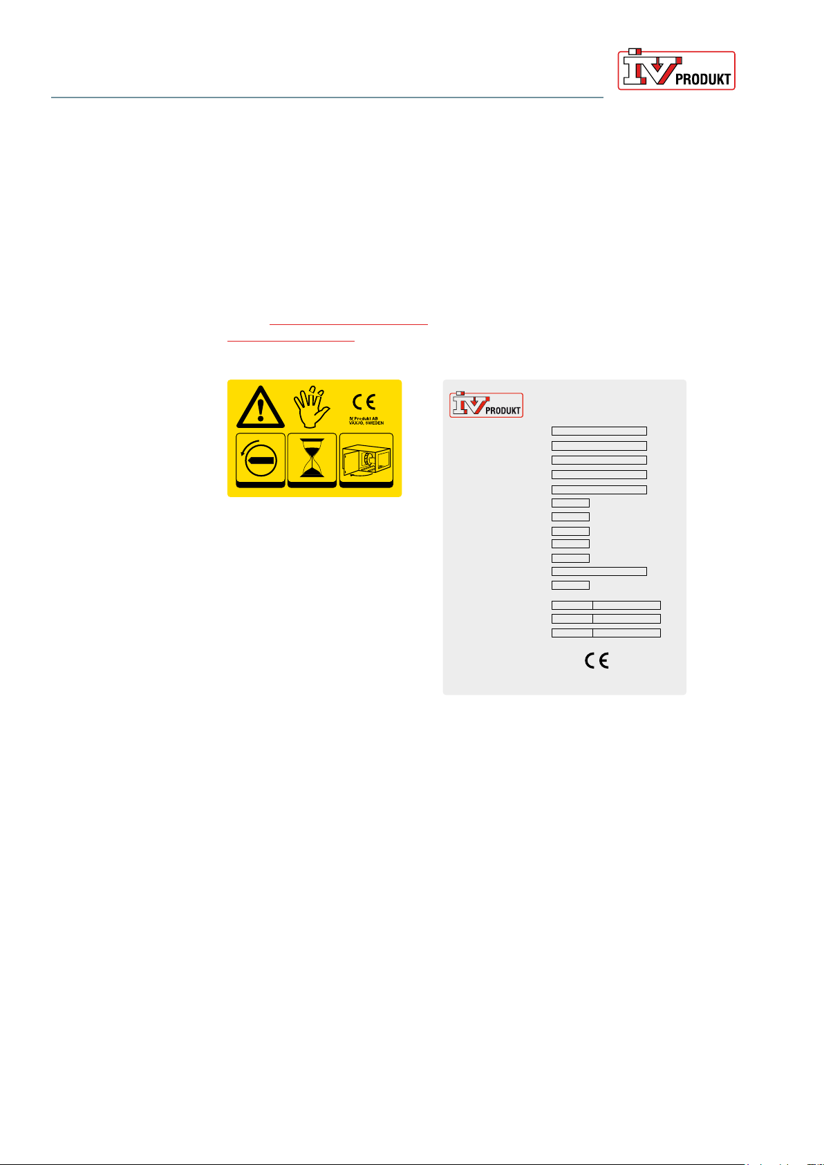
2.4 CE marking and EU Declaration of Conformity
The air handling units and cooling unit or reversible heat pump (if selected) are
CE marked, which means that upon delivery they conform to applicable provisions in EU Machinery Directive 2006/42/EC as well as to other EU Directives
applicable to the types of air handling units, e.g. Pressure Equipment Directive
PED 2014/68/EU.
As certification confirming that the requirements have been met, we provide an EU Declaration of Conformity, which is available under Documentation at ivprodukt.docfactory.com, or under Order Unique Documentation at
docs.ivprodukt.com.
1
s
0
12 3
180
Art. Nr. 19194-0001_01
Typical CE label for air handling units
Order number
Code Key
Model
Name of project
Date of manufacture
PS Max allowable pressure
PT Test pressure
TS Temperature range
Protection level - low
Protection level - high
Refrigerant / Fluid group
GWP
Refrigerant charge Circuit 1
Refrigerant charge Circuit 2
Refrigerant charge Circuit 3
Cooling unit
bar (e)
bar (e)
°C
bar (e)
bar (e)
kg
kg
kg
ton CO
ton CO
ton CO
2e
2
e
2e
Typical CE label for cooling units
For units without integrated control equipment
The EC declaration applies only to units in the condition in which they have been
delivered and installed at the facility in accordance with the enclosed installation
instructions. The declaration does not include components that were subsequently added or measures subsequently taken on the unit.
2.5 Maintenance
The ongoing maintenance of this unit can be carried out either by the person
normally in charge of maintaining the building or through a contract with a wellreputed service company.
Contains fluorinated greenhouse gases
covered by the Kyotot protocol.
0409
IV Produkt AB
VÄXJÖ, SWEDEN
Continuous product development may give rise to specification changes without notice.
2.6 Handling of refrigerant
The following information summarises the requirements and guidelines for handling the refrigerant used in cooling units. For further information, see the F-gas
Regulation (EU/517/2014 on fluorinated greenhouse gases) and the Swedish
Refrigerant Regulation (SFS 2016:1128). The purpose of the regulations is to
contribute to achieving EU goals for reduced climate impact in accordance with
the Kyoto Protocol.
Operator responsibilities
Generally speaking, the unit operator must:
• Minimise and prevent leakage
• Take corrective action to remedy any leakage that arises
• Ensure that leak inspection, service and repair of the refrigerant circuit are
carried out by a certified refrigeration technician
Operation and Maintenance
Envistar Top 04-21
DSET.190501.01.EN
Page 9
• Ensure that refrigerant is handled in an environmentally secure manner and in
accordance with national regulations.
By operator, we refer to the European Parliament’s definition: “...the natural or
legal person exercising actual power over the technical functioning of the equipment and systems...”.
The levels for the various actions to be taken for a system are calculated using
carbon dioxide equivalents, CO2e (tonnes). This figure is calculated by multiplying the refrigerant’s GWP value (Global Warming Potential) by the filling amount
in kilos. GWP for R410a is 2088. A filling amount of 1.1 kg R410a therefore corresponds to (1.1×2088)/1000 = 2.30 CO2e(tonnes).
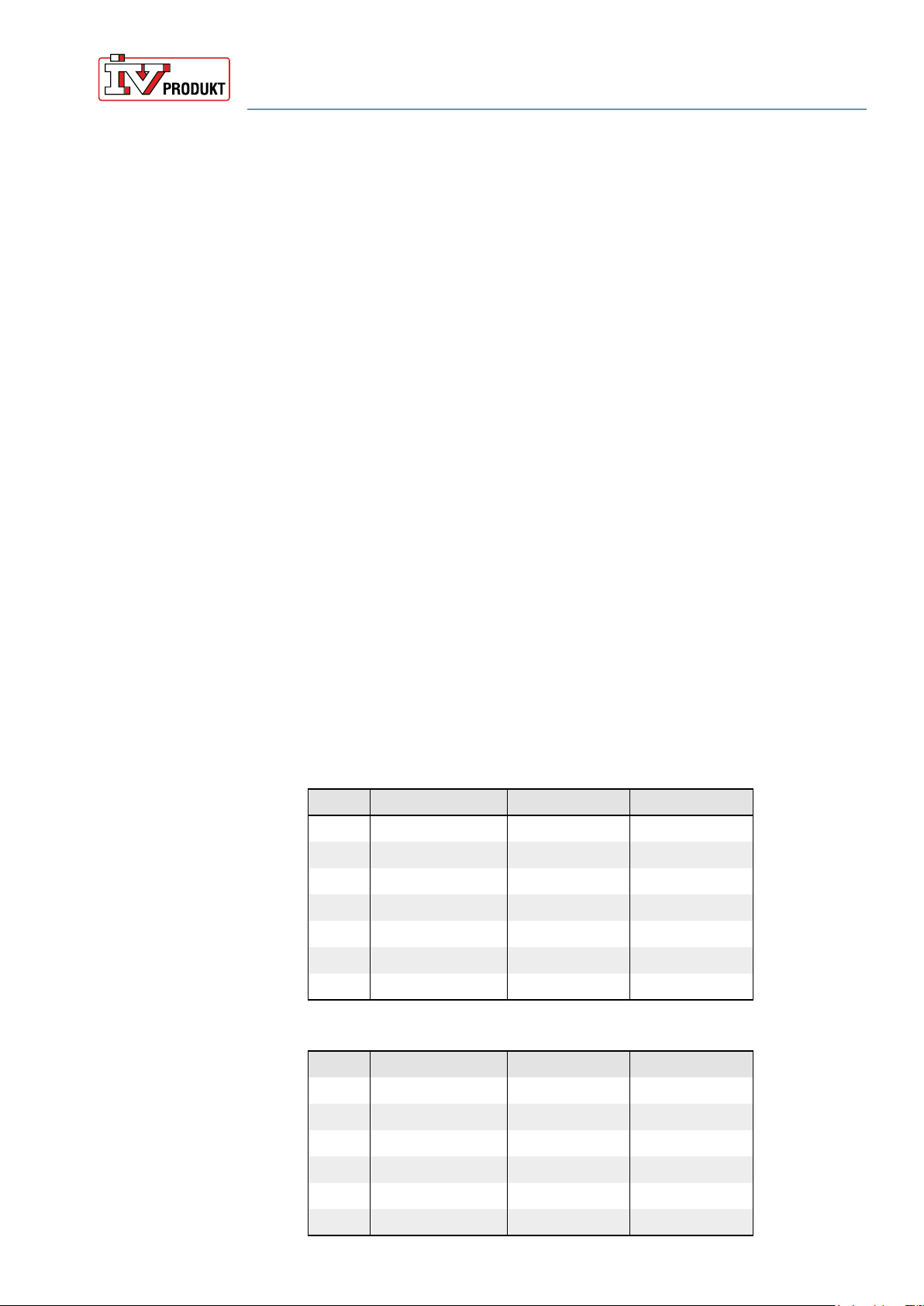
The unit is marked with refrigerant quantity and carbon dioxide equivalent.
Envistar Top with cooling unit (TEC)
Size Refrigerant Refrigerant volume CO2e (tonnes)
04 R410a 1.1 kg 2.30
06 R410a 1.7 kg 3.55
09 R410a 1.9 kg 3.97
10 R410a 2.1 kg 4.38
12 R410a 2.38 kg 4.97
16 R134a 5.0 kg 7.15
21 R134a 5.2 kg 7.44
Envistar Top with reversible heat pump (TTC)
Size Refrigerant Refrigerant volume CO2e (tonnes)
06 R410a 1.75 kg 3.65
09 R410a 2.8 kg 5.85
10 R410a 2.7 kg 5.64
12 R410a 4.1 kg 8.56
16 R410a 4.9 kg 10.23
21 R410a 6.68 kg 13.95
Continuous product development may give rise to specification changes without notice.

Operation and Maintenance
Envistar Top 04-21
Page 10
DSET.190501.01.EN
Leakage inspection and registration
For Envistar Top with cooling unit (TEC) size 16-21 and reversible heat pump
(code TTC) size 16-21 the following applies:
• Leakage inspection must be carried out by a certified refrigeration technician:
– When installing/commissioning the unit
– Periodically at least once per 12 months,
i.e. no more than 12 months between inspections
– within one month of any work being performed (e.g. sealing a leak, replacing a
component).
• The operator must record events, such as the volume and type of refrigerant
topped up, refrigerant taken into possession, results of inspections and work
done, person and company who carried out service and maintenance.
Envistar Top with cooling unit (code TEC) size 04-12 and reversible heat pump
(code TTC) size 06 is not subject to registering or leakage inspection requirements.
2.7 Extended warranty
In cases in which the equipment delivered falls under a 5-year warranty, in accordance with ABM 07 with supplement ABM-V 07 or in accordance with NL 09
with supplement VU13, the IV Produkt Service and Warranty Manual is supplied
with the product.
In order to lay claim to an extended warranty, a complete, documented and
signed IV Produkt Service and Warranty Manual must be presented.
2.8 Spare parts
Spare parts and accessories for this unit are ordered from your nearest IV
Produkt sales representative. When ordering, state the order number and
designation. These are stated on a model type plate, affixed to each component.
There is a separate spare parts list for the unit, refer to Order Unique
Documentation at docs.ivprodukt.com.
2.9 Dismantling and decommissioning
When an air handling unit is to be dismantled, separate instructions must be followed, see Dismantling and decommissioning the AHU under Documentation at
ivprodukt.docfactory.com.
Continuous product development may give rise to specification changes without notice.
Operation and Maintenance
Envistar Top 04-21
DSET.190501.01.EN
3 Technical description
3.1 Envistar Top air handling unit
Page 11
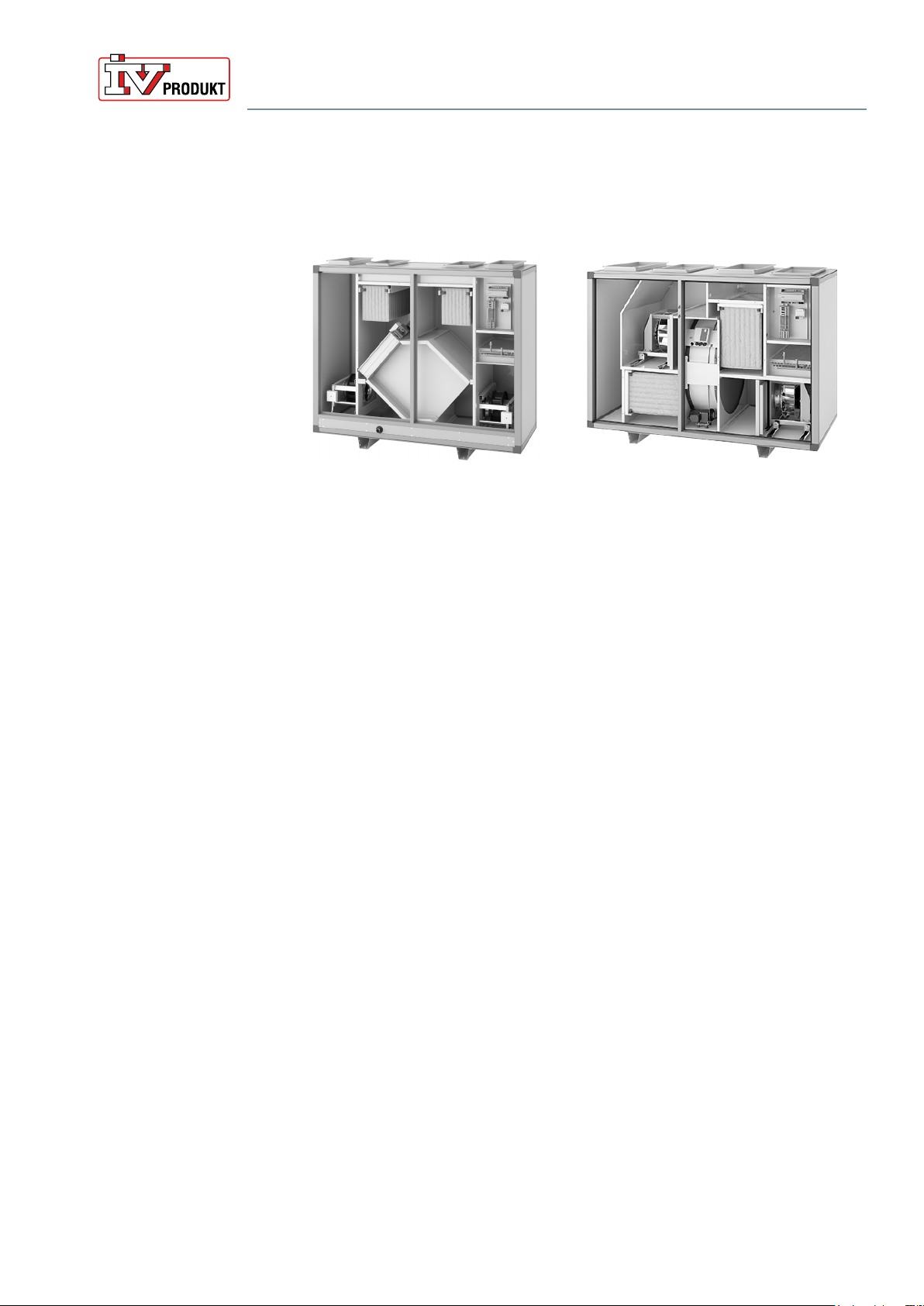
Envistar Top with counter-flow exchanger (code
TEM)
Envistar Top is manufactured as a compact unit or modularly, depending on the
size and version selected.
The compact unit is supplied complete preassembled from the factory. Modular
units are supplied in parts to facilitate transport and entry and are assembled on
site
The unit is available in different sizes and in right-hand or left-hand versions. All
units have duct connections in the top (up). The units are equipped with either a
counter-flow exchanger (code TEM/TXM) or rotary heat exchanger (code TER/
TXR).
The units are usually supplied with integrated control equipment, but can also be
obtained without control equipment.
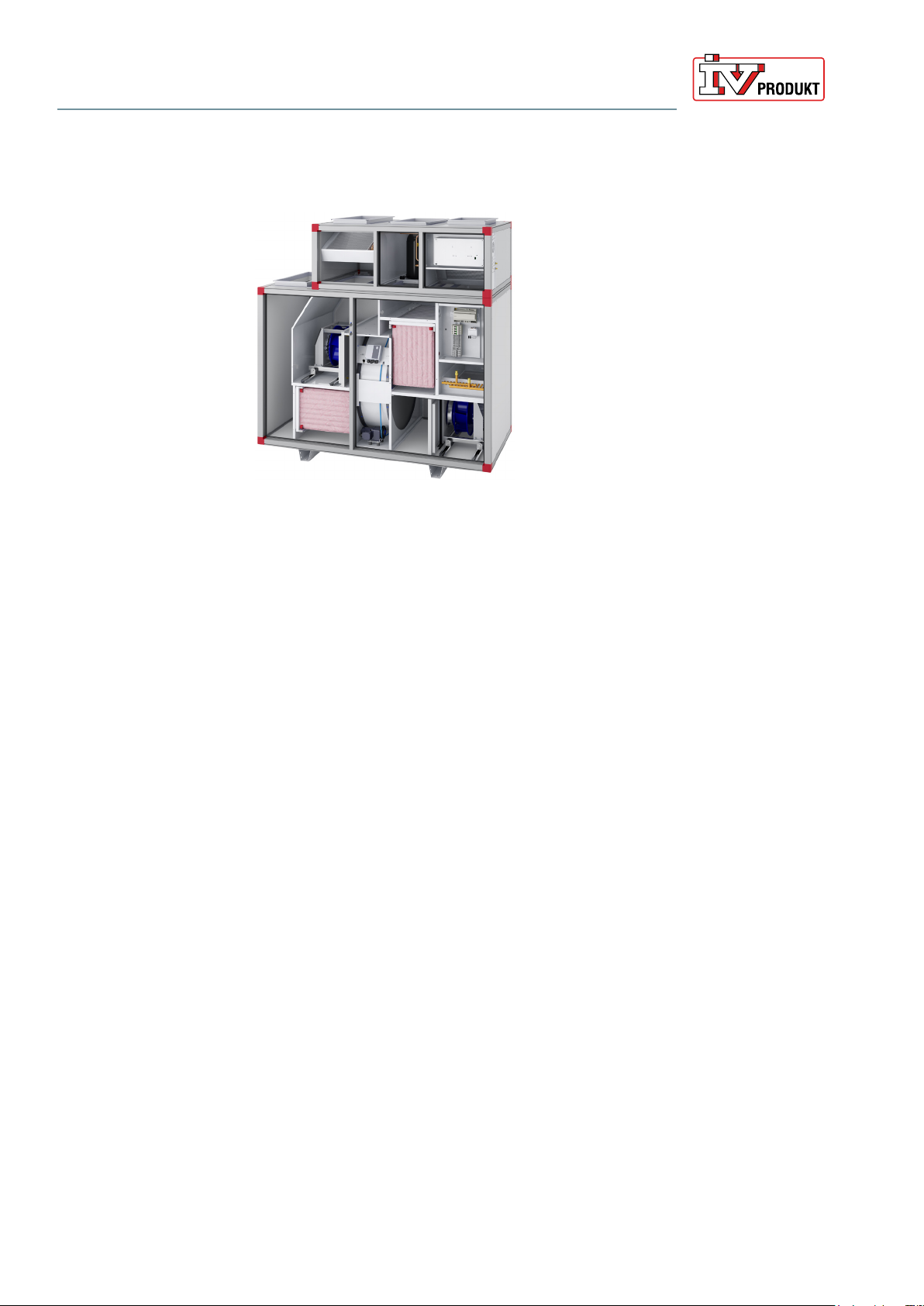
3.2 Home Concept model
Units with a rotary heat exchanger or counter-flow exchanger in the
Home Concept versions have, among other things, specialised control
equipment such as automatic defrosting. Units with rotary heat exchangers are
also equipped with a pressure balance function for optimal rotor operation.
Envistar Top with rotary heat exchanger (code TER)
Continuous product development may give rise to specification changes without notice.
Operation and Maintenance
Envistar Top 04-21
Page 12
DSET.190501.01.EN
3.3 EcoCooler cooling unit (code TEC)
Envistar Top with EcoCooler (code TEC) size 10
The integrated cooling unit with EcoCooler (code TEC) cooling recovery
is available as an optional extra to an Envistar Top unit with a rotary heat
exchanger. Cooling recovery means that the heat exchanger starts up when the
extract air/room temperature drops below the outdoor temperature and cooling
is required.
The unit has an electronic expansion valve, rotary compressor size 04, scroll
compressor size 06-12 and reciprocating compressor size 16-21.
Compressor
Power control takes place with a speed-controlled compressor. When
increased cooling is required, the frequency inverter increases the speed of the
compressor.
Compressor protection
In the event of an alarm initiated by the frequency inverter or the safety circuit,
the compressor stops and an alarm indication is given. If the unit is equipped
with control equipment, the alarm can be read on the Climatix display.
In the event of an alarm, correct the fault and then reset the alarm. If the safety
circuit alarm trips repeatedly, an authorised refrigeration service company must
be called in.
For size 04-12
The safety circuit consists of a high pressure switch (HP), which protects by tripping when there is high pressure in the system. Use the manual reset button on
the pressure switch to perform a reset.
For size 16-21
The safety circuit consists of a low pressure control and a high pressure switch
with a manual reset button. The safety circuit can trip for two different faults:
• High pressure in the system, HP (manual reset on the pressure switch)
• Low pressure in the system, LP (resets itself automatically)
Continuous product development may give rise to specification changes without notice.

Cooling function
Circuit board
Operation and Maintenance
Envistar Top 04-21
DSET.190501.01.EN
For integrated control equipment (MX), the cooling unit is interlocked across
the ventilation unit. If any of the fans stop, the cooling unit will also stop. The
interlock and demand signal is sent via Modbus.
For external control equipment (US, UC, MK), the interlock signal must be sent
via a potential-free relay. The demand signal must be sent via 0–10 V.
The cooling unit has internal communication between the frequency inverter and
the expansion valve’s control equipment. Communication takes place through
the Modbus protocol.
The circuit board in the cooling unit is internally prewired and tested at the factory.
The circuit board contains:
Page 13
Size 04:
Control centre with integrated expansion valve controller
Size 0 6 -12 :
• Compressor inverter
• Expansion valve controller
• Contactor
Size 16-21:
• Main switch
• Fuse
• Control unit
• Control unit for expansion valve
Continuous product development may give rise to specification changes without notice.
Operation and Maintenance
Envistar Top 04-21
Page 14
DSET.190501.01.EN
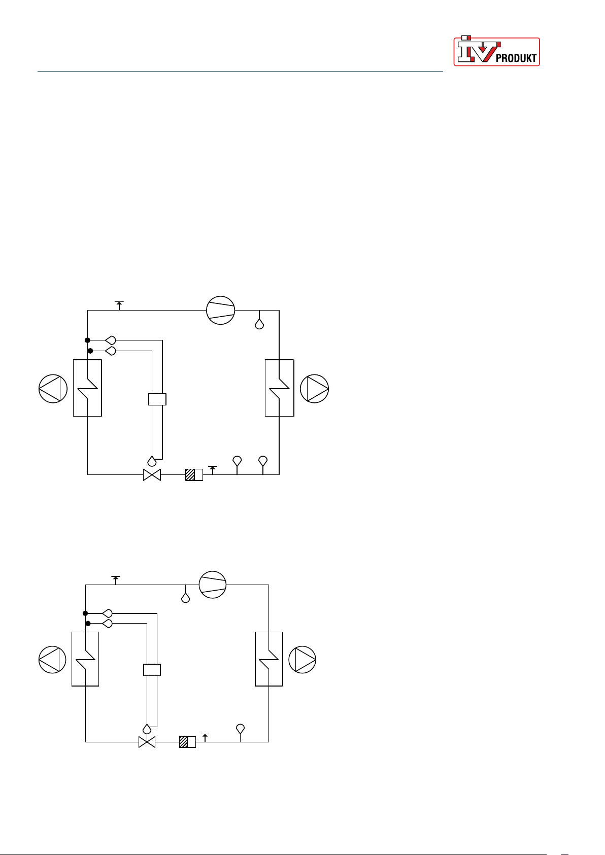
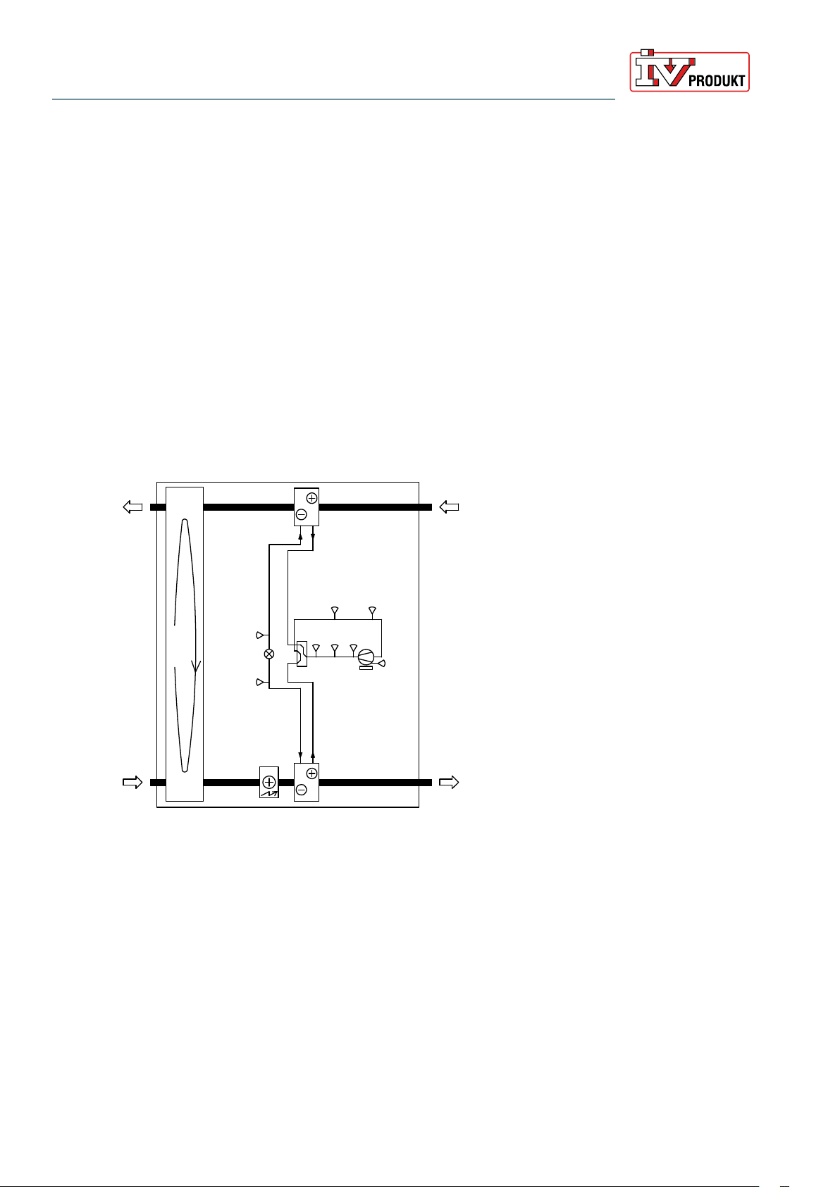
Cooling circuit function
From the compressor, the refrigerant is compressed as hot gas to the condenser, where heat is emitted. The refrigerant condenses from gas to liquid when it is cooled by the extract air.
The refrigerant passes the pressure reducing expansion valve and undergoes a phase transformation
in the evaporator from liquid to gas (the refrigerant evaporates).
Inside the evaporator, the refrigerant absorbs the heat required for phase transformation. The heat is
taken from the supply air which is thus cooled.
The cold refrigerant in gaseous form is drawn back into the compressor, where it is compressed and
thus heated. The gas is also used for cooling the compressor’s electric motor. The refrigerant now contains the heat from the supply air, the compressor’s motor heat and the compression heat.
12
15
1
14
13
10
6
7
9
8
Flow chart for refrigerant system size 04-12
10
14
13
8
11
12
1
4
5
1 Compressor
2 Hot gas sensor
2
3
5
3 Condenser
4 Extract air fan
5 High pressure switch
6 Pressure sensor - high pressure
7 Measurement outlet – high pressure
8 Drying filter
9 Expansion valve
411
10 Evaporator
11 Supply air fan
12 Measurement outlets – low pressure
13 Control unit
14 Suction gas sensor (temp after evaporator)
15 Pressure sensor – low pressure
1 Compressor
2 Condenser
3 Extract air fan
4 High pressure switch
5 Measurement outlet – high pressure
6 Drying filter
7 Expansion valve
8 Evaporator
9 Supply air fan
39
2
10 Measurement outlets – low pressure
11 Low pressure control
12 Control unit
13 Suction gas sensor (temp after evaporator)
14 Pressure sensor – low pressure
7
6
Flow chart for refrigerant system size 16-21
Continuous product development may give rise to specification changes without notice.
Operation and Maintenance
Envistar Top 04-21
DSET.190501.01.EN
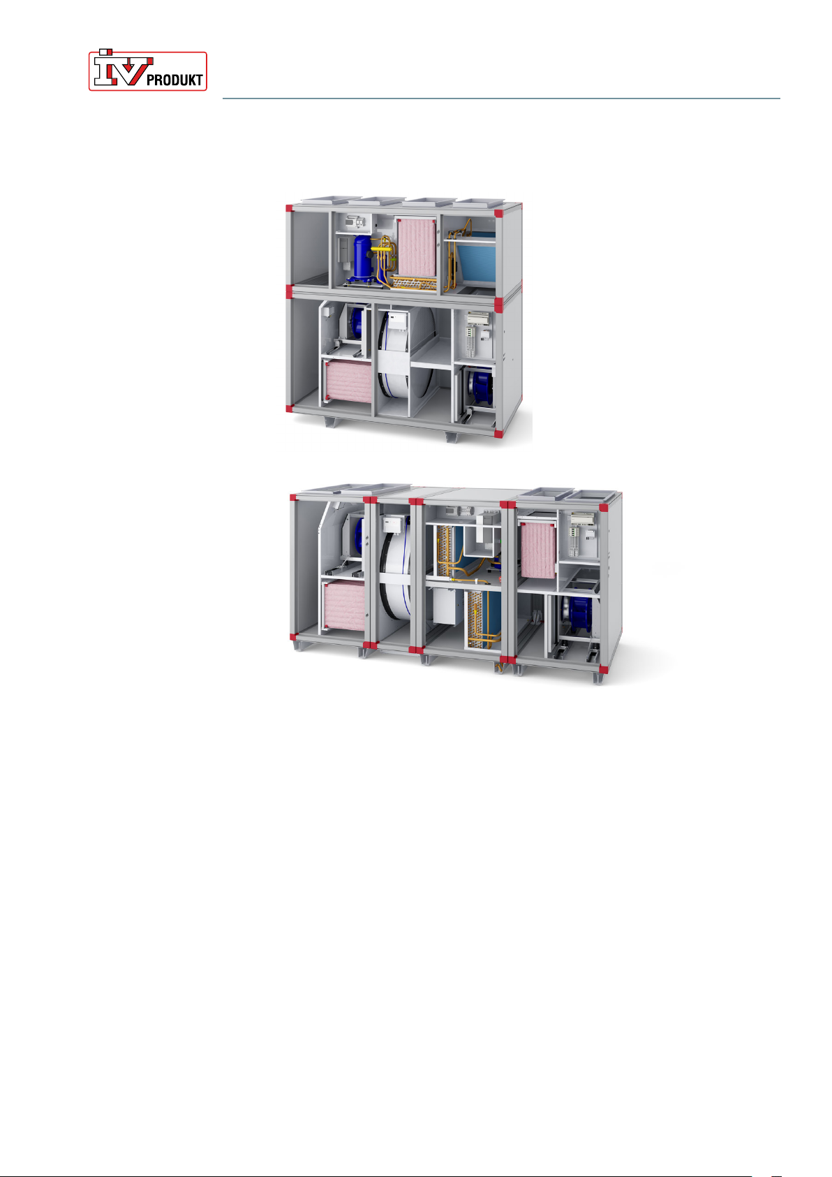
3.4 Reversible heat pump ThermoCooler HP (code TTC)
Page 15
Envistar Top with ThermoCooler HP (code TTC) size 10
Envistar Top with ThermoCooler HP (code TTC) Size 12
The integrated reversible heat pump ThermoCooler HP (code TTC) is available
as an optional extra to an Envistar Top unit with a rotary heat exchanger. The
units are intended to be used to cool or heat supply air in properties.
The heating pump function takes the heat content of the extract air and reuses
it, supplying the same heat to the ventilation unit’s supply air.
The cooling function moves the heat content in the supply air to the exhaust air,
where it can be emitted.
The unit has an electronic expansion valve and scroll compressor.
Continuous product development may give rise to specification changes without notice.
Page 16
Cooling circuit function
Cooling mode
From the compressor (1), the refrigerant is pushed as hot gas to the condenser
(the extract air coil) where the heat is emitted. The refrigerant condenses from
gas to liquid when it is cooled by the extract air.
The refrigerant passes the pressure reducing expansion valve (4) and undergoes
a phase transformation in the evaporator from liquid to gas (the refrigerant
evaporates).
Inside the evaporator (the supply air coil), the refrigerant absorbs the heat
required for phase transformation. The heat is taken from the supply air which is
thus cooled.
The cold refrigerant in gaseous form is drawn back into the compressor (1),
where it is compressed and thus heated. The gas is also used for cooling the
compressor’s electric motor. The refrigerant now contains the heat from the
supply air, the compressor’s motor heat and the compression heat.
Operation and Maintenance
Envistar Top 04-21
DSET.190501.01.EN
15
13
2
3
10
4
11
17 18
Flow chart for refrigerant system
9
8
7
1
6
5
14
Heating mode
16
12
1 Compressor
2 Suction gas sensor (temp after evaporator)
3 Pressure sensor, low pressure
4 Expansion valve
5 Frequency inverter
6 4-way valve
7 High pressure switch
8 Pressure sensor, high pressure
9 Temperature sensor, hot gas
10 Temperature sensor liquid line cooling
11 Temperature sensor liquid line heating
12 Temperature sensor sump
13 Extract air coil (condenser/evaporator)
14 Supply air coil (condenser/evaporator)
15 Exhaust air
16 Extract air
17 Outdoor air
18 Supply air
The function of heating mode is similar to that of cooling mode. The difference
between the cooling and heating modes is that the 4-way valve is in the
heating position. This means that the extract air coil, which was a condenser in
cooling mode, is now an evaporator. Conversely, the supply air coil becomes a
condenser.
Continuous product development may give rise to specification changes without notice.

Compressor
Operation and Maintenance
Envistar Top 04-21
DSET.190501.01.EN
The extract air is the heat pump’s energy source. When the extract air meets the
extract air coil, it is cooled since the coil functions as an evaporator. From the
evaporator, the refrigerant moves to the compressor, where it is compressed.
The refrigerant then moves to the supply air coil, where the energy from the
extract air and the compressor is released. The energy remaining downstream of
the heat pump is then recovered in the rotor.
These two recovery systems combined give a very high degree of efficiency.
Since the rotor requires less energy to run than the compressor system, this will
be in the first instance. The compressor will only start when the rotor’s energy
recovery is insufficient to heat the supply air.
Power control takes place with a speed-controlled PM scroll compressor. In the
event of an increased power requirement, the frequency inverter will increase the
speed of the compressor.
Page 17
Compressor protection
In the event of an alarm initiated by the control equipment or the safety circuit,
the compressor stops and an alarm indication is given. The alarm can be read
on the Climatix display or the Carel unit on the unit’s circuit board.
In the event of an alarm, correct the fault and then reset the alarm. If alarm trips
repeatedly, an authorised refrigeration service company must be called in.
The cooling/heating pump will primarily trip alarms for the following errors:
• High pressure in the system, manual reset on pressure control HP1
• Low pressure in the system
• Alarm from frequency inverter
Function
The reversible heat pump is interlocked across the ventilation unit. If any of the
fans stop, the cooling/heating pump will also stop. The unit will not start unless
the minimum flow is achieved. If a trim heater is installed, the minimum flow
must also be reached before start up is permitted.
Heating mode is blocked if the return air temperature does not reach the permitted minimum temperature.
The interlock and demand signal is sent via Modbus.
Circuit board
The circuit board for the unit contains:
• Main switch
• Fuses
• Control unit
The circuit board is installed inside the unit and is internally prewired and tested
at the factory.
Continuous product development may give rise to specification changes without notice.

Operation and Maintenance
Envistar Top 04-21
Page 18
DSET.190501.01.EN
4 Wiring instructions and fuse protection
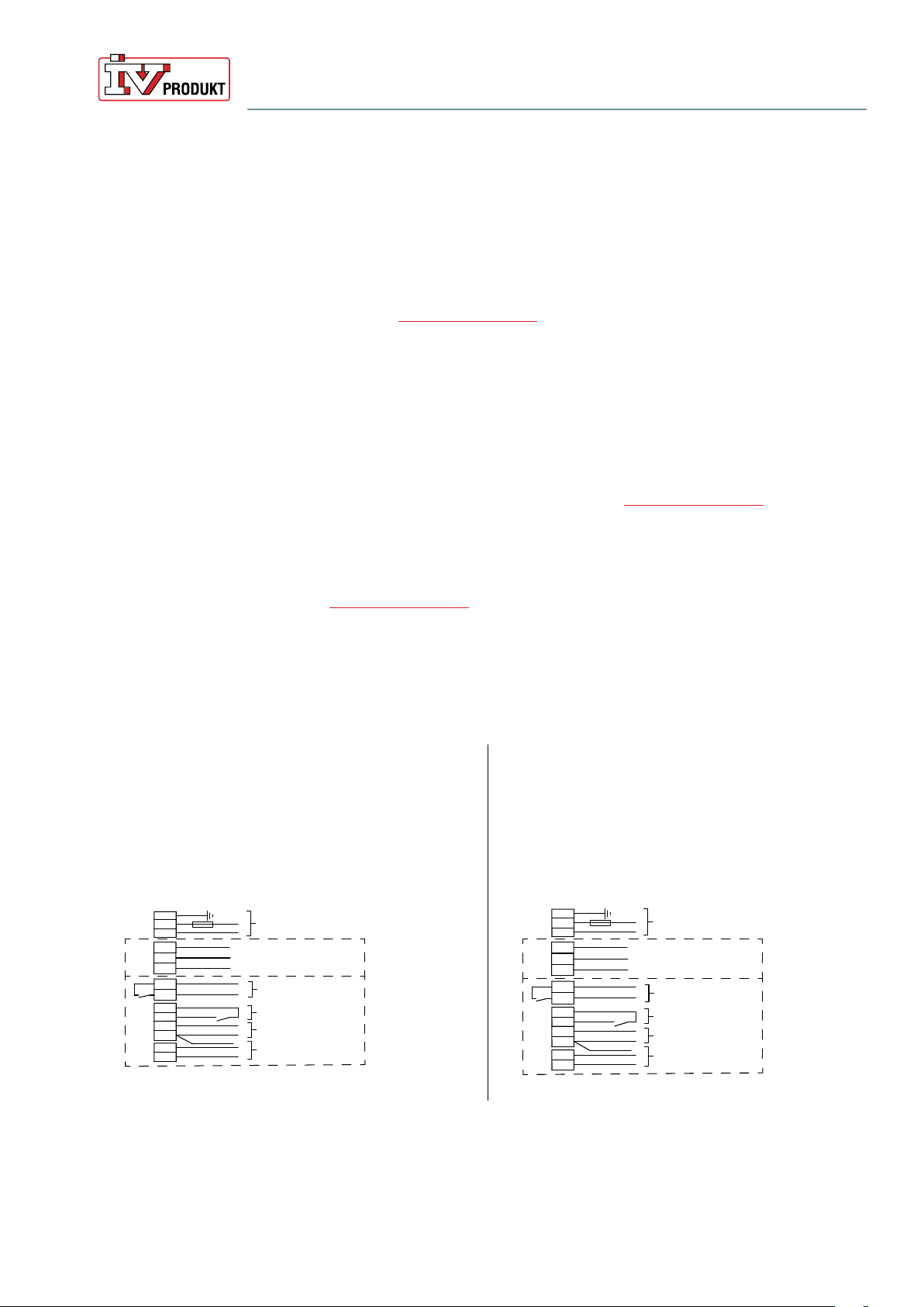
4.1 MX – Complete control equipment and UC – Complete electrical connection to terminal without controller unit
Applies to:
• Code MX - units supplied prewired with complete, integrated Siemens Climatix control equipment.
• Code UC - units supplied without controller unit but with sensor and damper
actuator connected electrically to the terminal. Fans and heat exchangers
are fused and connected electrically to the terminal. The terminal connections are positioned at a shared place in the unit. For further connection to
an external process unit, we recommend using a multi-conductor cable.
Safety switch
A safety switch must be fitted and wired on each power supply.
Wiring diagrams
For wiring diagrams for units with control equipment, see the order-unique wiring
diagram supplied with the unit at docs.ivprodukt.com (Control Diagram).
Unit functions, power supply and fuse protection
For recommended fuses, refer to Order Unique Documentation at
docs.ivprodukt.com (Technical Data and Control Diagram), or the product
program IV Produkt Designer.
• The unit has a shared power supply for all unit functions as standard, but
can be ordered with separate power supplies on special order.
• Electric heaters (air heater electric) have a power supply 3x400 V as standard.
A special coil or a transformer is required for a 230 V power supply.
• Fuses with type C characteristics are recommended.
Continuous product development may give rise to specification changes without notice.
Operation and Maintenance
INKOPPLING / WIRING
Ziehl 1×230 V - DC
PE
L1
N
Kraft matning 1×230 V ~ 50 Hz
Power suppl y 1×230 V ~ 50 Hz
Art. Nr. 19151-04 31_00
MX
IVP-styr
IVP Contr ols
MK
UC
US
Exter n styr
External
controls
A (D+)
B (D-)
Brun/Brown
GND
Vit/White
Blå/Blue
E1 +
+
-
GND
-
A (D+)
B (D-)
11
14
Styrn ing 0-10 V =
Control 0-10 V =
RS-4 85 Modbus
D1
24 V
Brandfunktion
Fire mode
LARM
(Bry ter vid larm)
ALARM
(Opens whe n triggered)
Ref.
Vit/White
Brun/Brown
Grå/Grey
Rosa/Pink
Gu l/Ye llow
Grön/Green
A (D+)
B (D-)
Brun/Brown
GND
Vit/White / Gul/Yellow
Blå/Blue / Grön/Green
E1 +
+
-
GND
-
A (D+)
B (D-)
11
14
Styrn ing 0-10 V =
Control 0-10 V =
RS-4 85 Modbus
D1
10 V
Brandfunktion
Fire mode
LARM (Br yter vid larm)
ALARM (Op ens when trigge red)
Ref.
Vit/White
Brun/Brown
Grå/Grey
Rosa/Pink
Gul/Yel low
Grön/Green
PE
L1
N
Kraft matning 1×230 V ~ 50 Hz
Power supp ly 1×230 V ~ 50 Hz
INKOPPLING / WIRING
Ziehl 1×230 V - BD
MX
IVP-styr
IVP Controls
MK
UC
US
Exter n styr
External
Controls
Art. Nr. 19151-04 30_01
Envistar Top 04-21
DSET.190501.01.EN
Page 19
4.2 MK – Fans and heat exchangers electrically connected to terminal
Code MK - units supplied without control equipment but with fans and heat exchangers connected electrically to terminals.
Connections to terminal blocks are located on each unit section.
For wiring instructions and recommended fuses, refer to Order Unique Documentation at docs.ivprodukt.com (Terminal Connection and Technical Data).
Safety switch
A safety switch must be fitted and wired on each power supply.
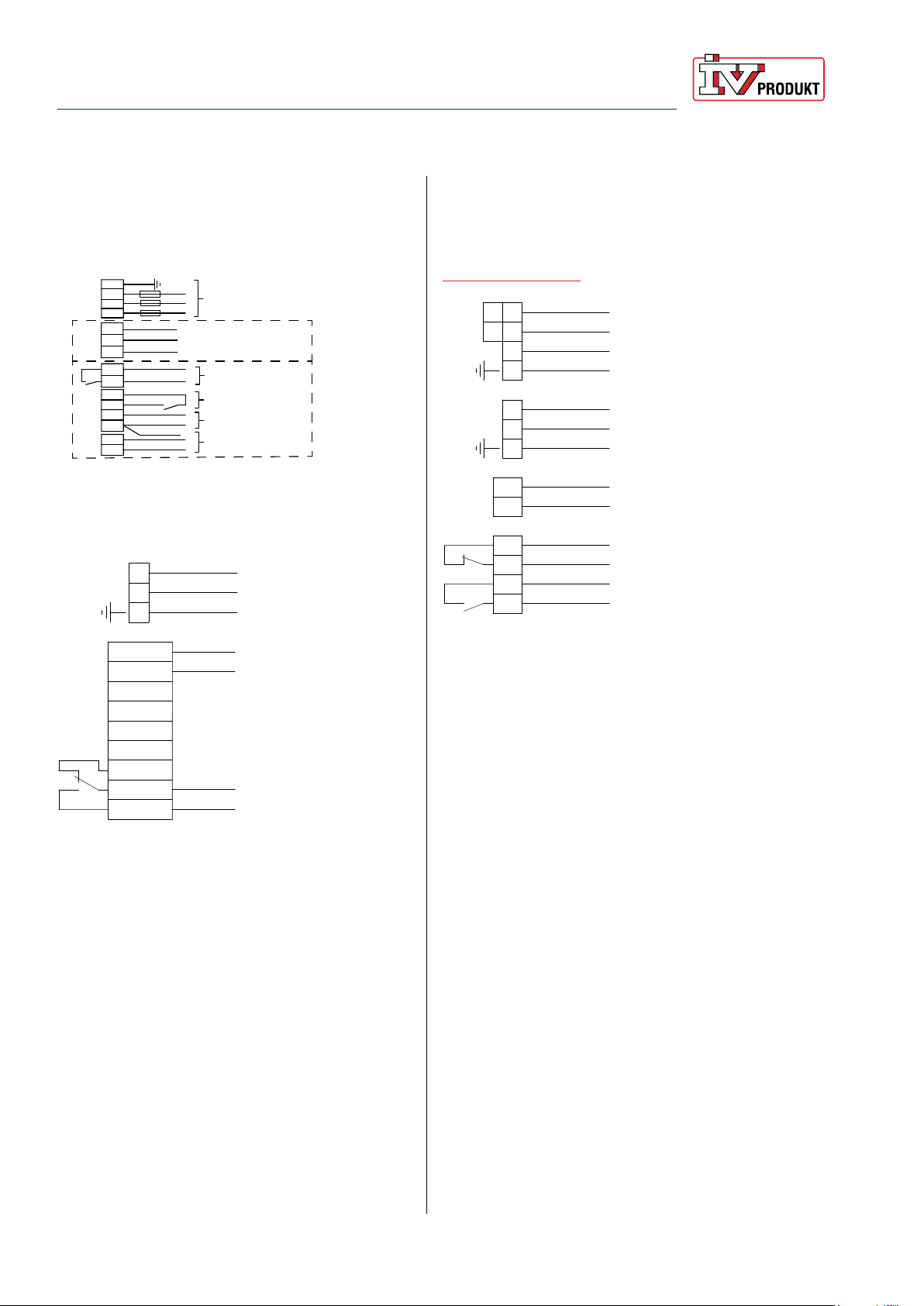
4.3 HS, US - Without control and without electrical connection
• Code HS - for units without control equipment and without electrical connection, control diagrams are available for the heat exchanger and cooling
unit under order unique documentation at docs.ivprodukt.com, for other
connection instructions, see below.
• Code HS - for units without control equipment and without electrical connection, control diagrams are available for the cooling unit under order
unique documentation at
docs.ivprodukt.com, for other connection instructions, see below.
Recommended fuse protection refers to fuses with type C characteristics.
Safety switch
A safety switch must be fitted and wired on each power supply.
Fans (code ELFF)
Ziehl EC 1×230 V 0.50 / 0.78 kW
fan impeller 025 / 028 / 031
Sizes 04, 06, 09 and 10
Ziehl EC 1×230 V 1.35 kW
fan impeller 031 / 035
Size 10 and 12
Continuous product development may give rise to specification changes without notice.
Page 20
INKOPPLING / WIRING
Ziehl 3×400 V - DC, DG
PE
L1
L2
Kraftmatning 3×400 V ~ 50 Hz
Power suppl y 3×400 V ~ 50 Hz
Art. Nr. 19151-04 32_01
MX
IVP-styr
IVP Contr ols
MK
UC
US
Exter n styr
External
controls
L3
A (D+)
B (D-)
Brun/Brown
GND
Vit/ White / Gul/Yellow
Blå/ Blue / Grön/G reen
E1 +
+
-
GND
-
A (D+)
B (D-)
11
14
Styrning 0-10 V =
Control 0-10 V =
RS-4 85 Modbus
D1
24 V
Brandfunktion
Fire mode
LARM
(Bry ter vid larm)
ALARM
(Opens wh en triggered)
Ref.
Vit/White
Brun/Brown
Grå/Grey
Rosa/Pink
Gu l/Ye llow
Grön/Green
Operation and Maintenance
Envistar Top 04-21
DSET.190501.01.EN
Ziehl EC 3×400 V 2.40 / 2.90 kW fan
impeller 040 / 045
Sizes 16 and 21
Rotor (Code TXRD)
L
N
PE
POWER SUPPLY
1×230 V AC
Air Heater electric (Code ETAB-EV*, ETKBEV**)
For power supply, output variant and recommended
fuse, refer to Order Unique Documentation at
docs.ivprodukt.com (Technical Data).
L1 L1
L2
L2
L3
PE
7
8
PE
Y
G0
1
2
3
4
POWER SUPPLY
OPERATION
1×230V~
+
CONTROL
0-10V=
–
NC
ALARM (CLOSES
BETWEEN 3-4 IN
EVENT OF ALARM)
NO
1: GND
2: 0-10V
8: NC
9: C
10: NO
–
CONTROL
+
ALARM (CLOSES IN
EVENT OF ALARM)
*For unit mounting, selectable for counter-flow exchanger and
rotary heat exchanger.
**For duct mounting, selectable for counter-flow exchanger
Continuous product development may give rise to specification changes without notice.
 Loading...