

IV Produkt Envistar Flex 060, Envistar Flex 1540 Operation And Maintenance Instructions
Operation and maintenance instructions
Translation of the original instructions
Order number :
Objects:
Air Handling Unit
Envistar Flex 060–1540 and Home Concept FTX Flex 060-600
Envistar® Flex


Unit specifications
Size
060 300 740
100 360 850
150 400 980
190 480 1250
240 600 1540
Filter, supply air
Coarse-60% (G4)
ePM10-60% (M5)
ePM10-75% (M6)
ePM1-60% (F7)
ePM1-85% (F8) / ePM1-85% (F9)
ePM1-70% (C7)
Black Ridge BR
Aluminium
Excl. filter
Filter, extract air
Coarse-60% (G4)
ePM10-60% (M5)
ePM10-75% (M6)
ePM1-60% (F7)
ePM1-85% (F8) / ePM1-85% (F9)
ePM1-70% (C7)
Aluminium
Excl. filter
Unit type
Home Concept Version
Control equipment
MX
US
UC
MK
HS
Unit parts and accessories
Plate heat exchanger EXP
Counter-flow exchanger EXM
Recovery rotor EXR
Run-around coil unit EXL
Air heater water EMT-VV, ELEV
ThermoGuard ESET-TV, ELTV
Air heater electric ESET-EV, ELEE
Eff-var 1 2 3 4 5
Air cooler water
ESET-VK, ELBC, ESET-DX, ELBD
Damper ESET-TR, EMT-01,
MIE-IU, EAU, EBE
Sound attenuator EMT-02, MIE-KL
Carbon filter section ECF
Filter bypass ENFT-10
Cooling unit ECO, ECX
Reversible heat pump TCH

Table of Contents
1 Safety precautions
1.1 Lockable safety switch ................................................................................................................ 6
1.2 Inspection doors .............................................................................................................................. 6
1.3 Electrical connection ..................................................................................................................... 6
1.4 Cooling unit/Revresible heat pump .................................................................................... 6
2 General
2.1 Intended use
....................................................................................................................................... 7
2.2 Manufacturer ....................................................................................................................................... 7
2.3 Designations ....................................................................................................................................... 7
2.4 CE marking and EU Declaration of Conformity ......................................................... 8
2.5 Maintenance ........................................................................................................................................ 8
2.6 Handling of refrigerant ................................................................................................................. 9
2.7 Extended warranty ....................................................................................................................... 10
2.8 Spare parts ........................................................................................................................................ 10
2.9 Dismantling and decommissioning ................................................................................. 10
3 Technical description
3.1 Envistar Flex air handling unit
.............................................................................................. 11
4 Wiring instructions and fuse protection
4.1 MX – Complete control equipment and
UC – Complete electrical connection to terminal (without DUC).
............. 12
4.2 MK – Fans and heat exchangers electrically connected to terminal .....12
4.3 HS, US - Without control and without electrical connection ........................ 13

Table of Contents, cntd
5 Operation
5.1 Hygiene inspection ...................................................................................................................... 17
5.2 Actions in case of standstill .................................................................................................. 17
5.3 Commissioning .............................................................................................................................. 18
6 Maintenance instructions
6.1 Service schedule
........................................................................................................................... 19
6.2 Filter ...................................................................................................................................................... 21
6.3 Rotary heat exchanger (code EXR) .................................................................................. 25
6.4 Plate heat exchanger (code EXP) ...................................................................................... 28
6.5 Run-around coil unit (code EXL) ........................................................................................ 30
6.6 Air heater water (code EMT-VV, MIE-CL/ELEV) ...................................................... 32
6.7 Air heater electric (code ESET-EV, MIE-EL/ELEE) ................................................ 34
6.8 Air cooler water (code ESET-VK, ESET-DX,
MIE-CL/ELBC, MIE-CL/ELBD) ............................................................................................ 35
6.9 Fan unit (code ELFF) .................................................................................................................. 36
6.10 Damper (code EBE, ESET-TR, EMT-01, MIE-IU, EAU) ...................................... 39
6.11 Sound attenuators (code EMT-02, MIE-KL) .............................................................. 40
6.12 Filter bypass (code ENFT-10) ............................................................................................... 41

Page 6
Operation and maintenance instructions
for Envistar Flex
DSEF181201.00.EN
Continuous product development may give rise to specification changes without notice.
1 Safety precautions
Observe warning labels on the unit as well as the following safety precautions:
1.1 Lockable safety switch
WARNING!
High voltage and rotating fan impeller, risk of personal injury.
Working on/servicing the unit – Shut down the unit via the service
switch in the control equipment, then turn the safety switch to the
0 position and lock it.
NB:
The safety switch is not designed for starting/stopping the unit. Always
use the service switch in the control equipment to start and shut down
the unit.
1.2 Inspection doors
WARNING!
Positive pressure inside the unit, risk of personal injury.
Allow the pressure to drop before you open the inspection doors.
WARNING!
Rotating fan impeller, risk of personal injury. Shut down the unit
via the service switch in the control equipment, then turn the
safety switch to the 0 position and lock it. Wait at least 3 minutes
before opening inspection doors.
NB:
The doors in front of moving parts should normally be locked; there are
no safety guards. Before carrying out work, unlock the doors with the key
provided.
1.3 Electrical connection
WARNING!
Rotating fan impeller, risk of personal injury. The unit must not be
energised until all ducts have been connected.
NB:
Wiring of connections and other electrical work may only be carried out
by a qualified electrician or by service personnel recommended by IV
Produkt.
1.4 Cooling unit/Revresible heat pump
WARNING!
Hot surfaces, risk of personal injury. Shut down the unit via the
service switch in the control equipment, then turn the safety
switch to the 0 position and lock it. Wait at least 30 minutes before
opening the compressor inspection doors.
Page 7
Operation and maintenance instructions
for Envistar Flex
DSEF181201.00.EN
Continuous product development may give rise to specification changes without notice.
2 General
2.1 Intended use
The air handling units in the Envistar Flex series are intended for comfort ventilation in buildings.
2.2 Manufacturer
The Envistar air handling units (AHUs) are manufactured by:
IV Produkt AB
Sjöuddevägen 7
SE-350 43 VÄXJÖ
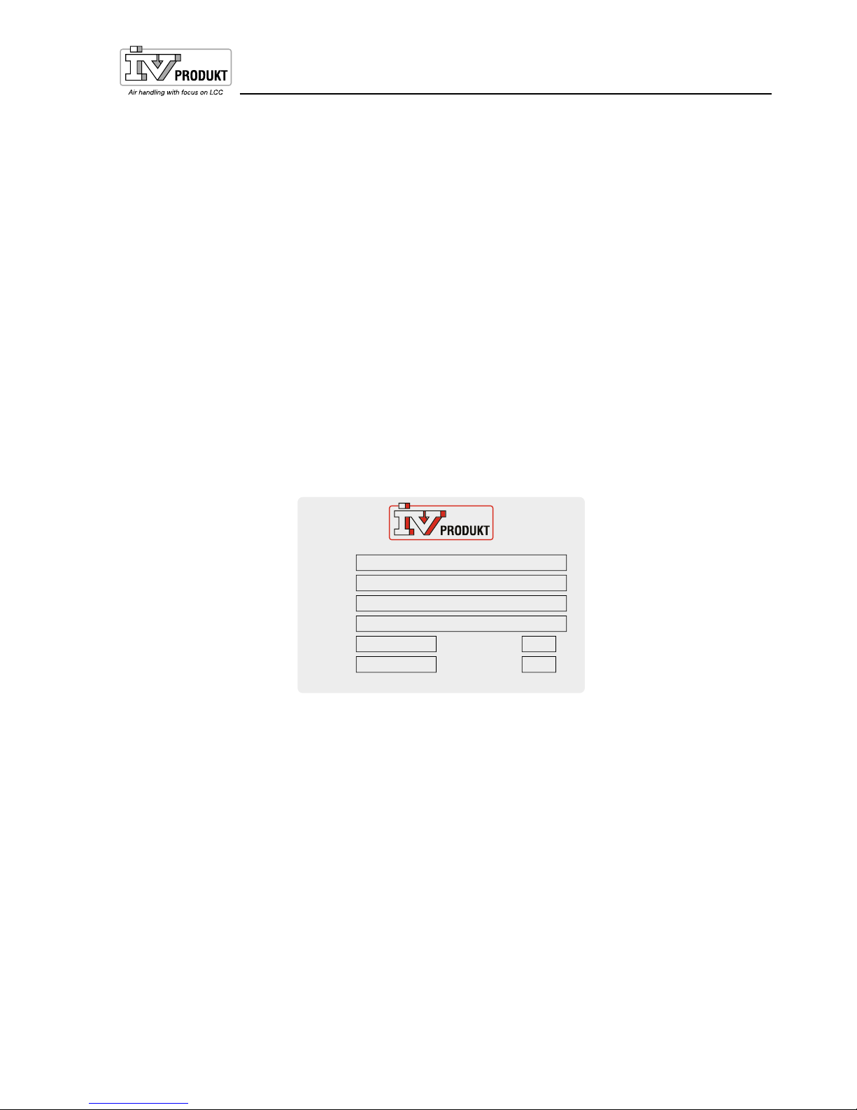
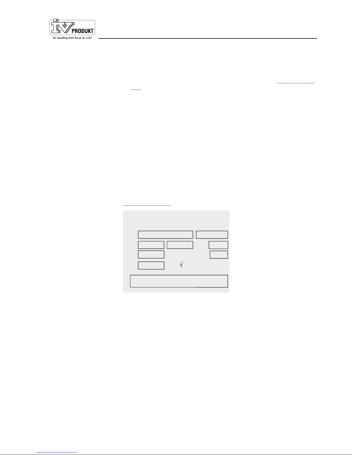
2.3 Designations
Envistar Flex air handling units consist of a number of different block sections.
Each block section is supplied with a model identification label located at the
front.
The model plate shows the order number and the required designations to identify the block part.
Kodnyckel
Code key
Beteckning
Project name
Ordernummer
Order number
Max. varv
Max. rev.
Tillv. ort
Made in
Tillv. månad
Manuf. month
YYMM
ENF-190-AA-00
Modell
Model
Envistar Flex
TA1 FA1 POS 1
1234-567
– –
VÄXJÖ, SWEDEN
Max. temp. °Cr/m
1805
Art. Nr. 19121-1001
Typical model identification label
Page 8
Operation and maintenance instructions
for Envistar Flex
DSEF181201.00.EN
Continuous product development may give rise to specification changes without notice.
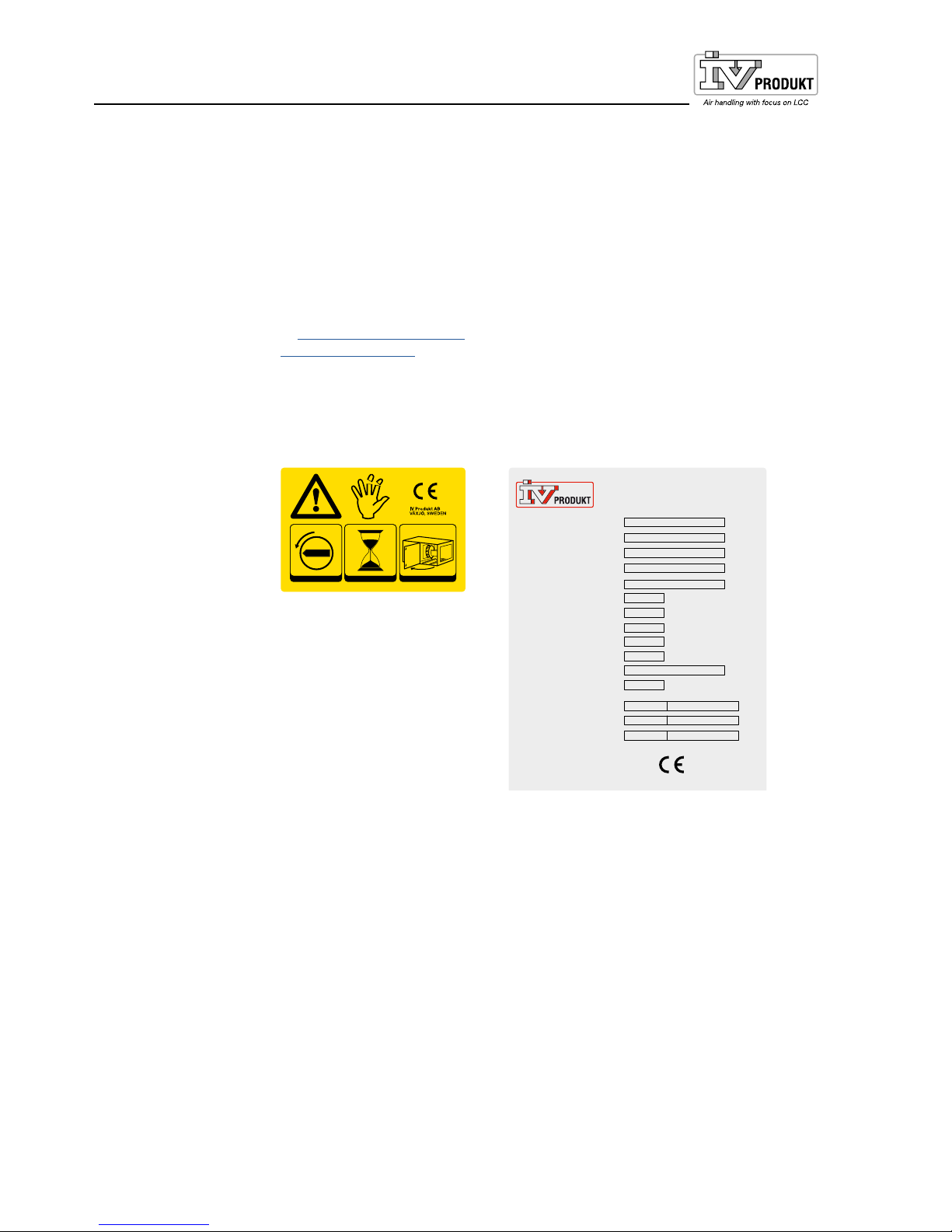
2.4 CE marking and EU Declaration of Conformity
The air handling units and any incorporated cooling units are CE marked,
which means that upon delivery they conform to applicable provisions in EU
Machinery Directive 2006/42/EC as well as to other EU Directives applicable to the types of air handling units, e.g. Pressure Equipment Directive PED
2014/68/EU.
As certification confirming that the requirements have been met, we provide
an EU Declaration of Conformity, which is available under Documentation
at ivprodukt.docfactory.com, or under Order Unique Documentation at
docs.ivprodukt.com.
The CE marking applies to units that IV Produkt AB manufactures and
supplies in the form of a unit without additional control equipment. For
the CE marking of IV products to apply, the applicable requirements of
the EU Machinery Directive 2006/42/EC and related directives for control
equipment shall be met when installed for the unit.
0
1
Art. Nr. 19194-0001_01
12 3
180
s
Typical CE label for air handling units
0409
Cooling unit
Order number
Code Key
Model
Name of project
Date of manufacture
PS Max allowable pressure
PT Test pressure
TS Temperature range
Protection level - low
Protection level - high
Refrigerant / Fluid group
GWP
Refrigerant charge Circuit 1
Refrigerant charge Circuit 2
Refrigerant charge Circuit 3
IV Produkt AB
VÄXJÖ, SWEDEN
Contains fluorinated greenhouse gases
covered by the Kyotot protocol.
bar (e)
bar (e)
°C
bar (e)
bar (e)
kg
kg
kg
ton CO
2e
ton CO
2
e
ton CO
2e
Typical CE label for cooling units
2.5 Maintenance
Continuous maintenance of this unit can be carried out either by the person
normally in charge of maintaining the building or through a contract with a
well-reputed service company.

Page 9
Operation and maintenance instructions
for Envistar Flex
DSEF181201.00.EN
Continuous product development may give rise to specification changes without notice.
2.6 Handling of refrigerant
The following information summarises the requirements and guidelines for handling the refrigerant used in cooling units. For further information, see the F-gas
Regulations (EU/517/2014) and the Refrigerant Regulations (SFS 2016:1128).
The purpose of the regulations is to contribute to achieving EU goals for reduced
climate impact in accordance with the Kyoto Protocol.
Operator responsibilities
Generally speaking, the unit operator must:
• Minimise and prevent leakage
• Take corrective action to remedy any leakage that arises
• Ensure that the service and repair of the refrigerant circuit is carried out by a
certified refrigeration technician
• Ensure that refrigerant is handled in an environmentally secure manner and
in accordance with national regulations.
By operator, we refer to the European Parliament’s definition: “...the natural or
legal person exercising actual power over the technical functioning of the equipment and systems...”.
The levels for the various actions to be taken for a system are calculated using
carbon dioxide equivalents, CO₂ e(ton). This figure is calculated by multiplying
the refrigerant’s GWP value (Global Warming Potential) by the filling amount in
kilos. GWP for R410a is 2088. A filling amount of 5.0 kg R410a therefore corresponds to
(5.0×2088)/1000 = 10.44 CO₂ e(tons). The unit is marked with refrigerant quantity and carbon dioxide equivalent.
Leakage inspection and registration
The following applies for single-units with 5 CO₂ e(tons) refrigerant content or
more per circuit:
• Leakage inspections must be carried out by a certified refrigeration technician:
– on installation/commissioning – periodically at least once every 12 months,
i.e. maximum 12 months between inspections
– within one month after any work is performed (e.g. sealing a leak, replacing
a component).
• The operator must record events, such as the volume and type of refrigerant
topped up, refrigerant recovered, results of inspections and work done, person and company who carried out service and maintenance.
If the total refrigerant content is below 5 CO₂ e (tonnes), no periodic leak detection or record keeping is needed, but the requirement for leak inspection during
installation does apply.
If the total refrigerant content of the ventilation system exceeds 14 CO₂ e(tons),
the result of the inspections (inspection report) must be sent to the regulatory
authorities and be in their possession no later than 31 March of the following
year. For a unit that will contain 14 CO₂e(tons) or more, the intended operator
must inform the supervisory authority of the installation well in advance.

Page 10
Operation and maintenance instructions
for Envistar Flex
DSEF181201.00.EN
Continuous product development may give rise to specification changes without notice.
2.7 Extended warranty
In cases in which the equipment delivered falls under a 5-year warranty, in accordance with ABM 07 with supplement ABM-V 07 or in accordance with NL 09
with supplement VU13, the IV Produkt Service and Warranty Manual is supplied
with the product.
In order to lay claim to an extended warranty, a complete, documented and
signed IV Produkt Service and Warranty Manual must be presented.
2.8 Spare parts
Spare parts and accessories for this unit are ordered from your nearest IV
Produkt sales representative. When ordering, state the order number and
designation. These are stated on a model type plate, affixed to each component.
There is a separate spare parts list for the unit, refer to Order Unique
Documentation at docs.ivprodukt.com.
2.9 Dismantling and decommissioning
When an air handling unit is to be dismantled, separate instructions must be followed, see Air handling unit, dismantling and decommissioning under
Documentation at ivprodukt.docfactory.com.
Page 11
Operation and maintenance instructions
for Envistar Flex
DSEF181201.00.EN
Continuous product development may give rise to specification changes without notice.
3 Technical description
3.1 Envistar Flex air handling unit
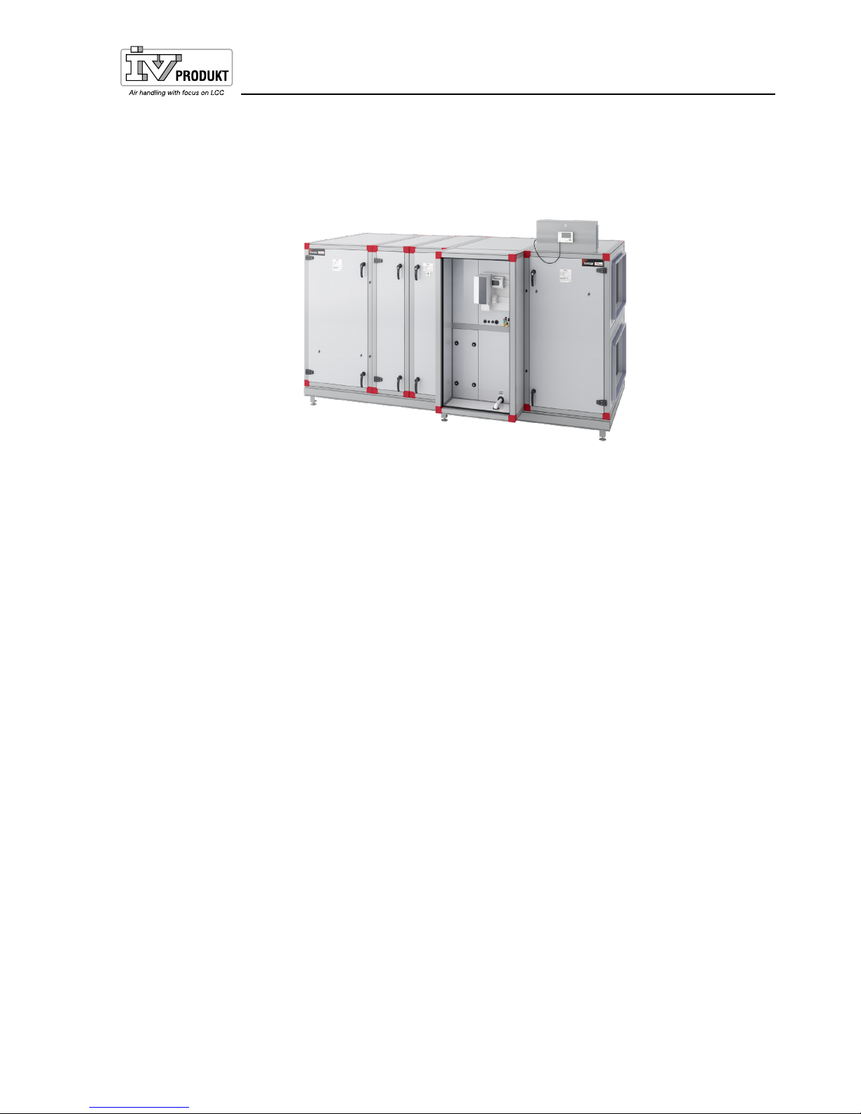
The Envistar Flex is manufactured as a modular unit comprising block sections
in various sizes. The versions are named according to the supply air and can be
freely selected: right-hand or left-hand, up or down.
The units are equipped with either a rotary heat exchanger, counter-flow heat
exchanger, plate heat exchanger or run-around coil unit.
The units are also available as single-stacked supply air or extract air units in
sizes 060-600.
The units are usually supplied with integrated control equipment, but can also be
obtained without control equipment.
Cooling units EcoCooler and Cooling heat pump ThermoCooler HP are available
as an option.

Page 12
Operation and maintenance instructions
for Envistar Flex
DSEF181201.00.EN
Continuous product development may give rise to specification changes without notice.
4 Wiring instructions and fuse protection
4.1 MX – Complete control equipment and UC – Complete electrical
connection to terminal (without DUC).
Applies to:
• units supplied prewired with complete, integrated Siemens Climatix control
equipment (code MX).
• units supplied without process unit (DUC) but with sensor and damper actuator connected electrically to the terminal (code UC). Fans and heat exchangers are fused and connected electrically to the terminal. The terminal
connections are positioned at a shared place in the unit. For further connection to an external process unit, we recommend using a multi-conductor
cable.
Safety switch
A safety switch is mounted on the air handling unit.
Wiring diagrams
For wiring diagrams for units with control equipment, see the order-unique wiring
diagram supplied with the unit at docs.ivprodukt.com (Control Diagram).
Unit functions, power supply and fuse protection
For power supply to the unit functions and recommended fuses, refer to Order
Unique Documentation at docs.ivprodukt.com (Technical Data and Control Diagram), or the product program IV Produkt Designer.
Recommended fuse protection refers to fuses with type C characteristics.
4.2 MK – Fans and heat exchangers electrically connected to terminal
For units supplied without control equipment but with fans and heat exchangers
connected electrically to terminals (code MK).
Connections to terminal blocks are located on each unit section.
For wiring instructions and recommended fuses, refer to Order Unique Documentation at docs.ivprodukt.com (Terminal Connection and Technical Data).
Safety switch
A safety switch must be fitted and wired on each power supply.
Page 13
Operation and maintenance instructions
for Envistar Flex
DSEF181201.00.EN
Continuous product development may give rise to specification changes without notice.
4.3 HS, US - Without control and without electrical connection
• For units without control equipment and without electrical connection (code
HS), a control diagram is available for the heat exchanger at docs.ivprodukt.
com, for other connection instructions, see below.
• For units without control equipment and without electrical connection (code
US), refer to the connection instructions below.
Recommended fuse protection refers to fuses with type C characteristics.
Safety switch
A safety switch must be fitted and wired on each power supply.
Fan, power supply and fuse protection
For separate power supply of each fan, read and note the “Type” from the fan
data plate.
NB: The fans may be different sizes/variants. Read both the supply air and extract air fan labels.
For the relevant power supply and recommended fuse protection, refer to
docs.ivprodukt.com (Technical Data).
Fläkt / Fan / Puhallin
Wentylator
/ Ventilator /
Ventilateur
ELFF-063G-PFD2-0400-1-F-D 225 1460
2 x 8,3
3x400
15 97
4,5
50
W2-063GE
A,Static
VSD Integrated
68,4 62 72,59
2 x 4
Q=1/K
x
p
(m³/s)
Type
-
r/m
kW A
V
Utfrekvens
Out frekvency
Taajuusalue
Czesttot. wyj.
Ausg.frequen
z
Fréq. sort
-
Hz
K-faktor
K-factor
KWsp
kerroin
.K
K-faktor
Facteur
Ref.
ErP data
Eff.degr.type
Speed ctrl.
ɳ total N
↔ N=
Max. temp.
°C
Typical fan data label

Page 14
Operation and maintenance instructions
for Envistar Flex
DSEF181201.00.EN
Continuous product development may give rise to specification changes without notice.
ELFF Ziehl EC
1×230 V 0.50-0.78 kW
fan impeller 025
Size 060
A (D+)
B (D-)
Brun/Brown
GND
Vit/White
Blå/Blue
E1 +
+
-
GND
-
A (D+)
B (D-)
11
14
Styrning 0-10 V =
Control 0-10 V =
RS-485 Modbus
D1
10 V
Brandfunktion
Fire mode
LARM
(Bryt er vid larm)
ALARM
(Opens wh en triggered)
Ref.
Vit/White
Brun/Brown
Grå/Grey
Rosa/Pink
Gul/Yel low
Grön/Green
PE
L1
N
Kraftmatning 1×230 V ~ 50 Hz
Power sup ply 1×230 V ~ 50 Hz
INKOPPLING / WIRING
Ziehl 1×230 V - BD
MX
IVP-styr
IVP Controls
MK
UC
US
Extern styr
External
Controls
Art. Nr. 19151-04 30_00
ELFF EBM EC
1×230 V 0.75 kW
fan impeller 028
Size 100
INKOPPLING / WIRING
EBM 1×230 V - P5
Art. Nr. 19151-040 0_00
PE
N
L
Kraftmatning 1×230 V ~ 50 Hz
Power sup ply 1×230 V ~ 50 Hz
MX
IVP-styr
IVP Controls
MK
UC
US
Extern styr
External
controls
RSA
RSB
Gul /Yel low
GND
Vit/White
Blå/Blue
+
-
+
-
RSA
RSB
NC
COM
Styrning 0-10 V =
Control 0-10 V =
RS-485 Modbus
LARM (Br yter vid larm)
ALARM (Opens wh en
triggered)
Ref.
Vit/White
Brun/Brown
Brun/Brown
GND
0-10V
Grön/Green
Yellow/Gre en
Vit 1/White 1
Vit 2/
White 2
Blå/Blue
Svart /Black
Kabel 1/Cab le 1 Kabel 2 /Cable 2
Gul/Grö n
Gul/Yel low
Brun/Brown
Brun/Brown
Blå/Blue
Blå/Blue
Vit/White
Vit/White
ELFF EBM EC
3×400 V 1.05 kW
fan impeller 028
Size 100
INKOPPLING / WIRING
EBM 3×400 V - P6
Art. Nr. 19151-040 1_00
PE
L1
L2
Kraftmatning 3×400 V ~ 50 Hz
Power supp ly 3×400 V ~ 50 Hz
MX
IVP-styr
IVP Controls
L3
MK
UC
US
Extern styr
External
controls
RSA
RSB
Gul/Yel low
GND
Vit/White
Blå/Blue
+
-
+
-
RSA
RSB
NC
COM
Styrning 0-10 V =
Control 0-10 V =
RS-485 Modbus
LARM (Br yter vid larm)
ALARM (Op ens when
triggered)
Ref.
Vit/White
Brun/Brown
Brun/Brown
GND
0-10V
Grön/Green
Yellow/Gre en
Vit 1/White 1
Vit 2/
White 2
Svart 1/Bla ck 1
Svart 1/Bla ck 1
Svart 1/Bla ck 1
Kabel 1/Cabl e 1 Ka bel 2/Cable 2
Gul/Grö n
Gul/Yel low
Brun/Brown
Brun/Brown
Blå/Blue
Blå/Blue
Vit/White
Vit/White
ELFF EBM EC
3×400 V 1.10-5.70 kW
fan impeller 031-056
Size 100-740
INKOPPLING / WIRING
EBM 3×400 V - P8, M3, M5
RSA
RSB
Gul/Yell ow
GND
Vit/White
Blå/Blue
+
-
+
-
RSA
RSB
NC
COM
Styrni ng 0 -10 V =
Control 0 -10 V =
RS-48 5 Modbus
LARM
(Bryte r vid larm)
ALARM
(Opens whe n triggered)
Ref.
Vit/White
Brun/Brown
Brun/Brown
GND
A in 1U
0-10V
Grön/Green
PE
L1
L2
Kraftm atning 3×400 V ~ 50 Hz
Power supp ly 3 ×400 V ~ 50 Hz
MX
IVP-styr
IVP Controls
L3
MK
UC
US
Extern st yr
External
controls
Art. Nr. 19151-040 2_00
ELFF DOMEL PFJ1
3×400 V 4.3-6.5 kW
fan impeller 063-071
Size 480-980
INKOPPLING / WIRING
OJ-DV 3×400 V
PE
L1
L2
Kraftmatning 3×400 V ~ 50 Hz
Power supp ly 3×400 V ~ 50 Hz
Art. Nr. 19151-048 0_00
MX
IVP-styr
IVP Controls
L3
MK
UC
US
Extern styr
External
controls
Bus B
GND
Gul/Yel low
GND
Blå/Blue
Brun/Brown
+
-
+
-
Bus A
Bus B
14 NC
15 C
Styrning 0-10 V =
Control 0-10 V =
RS-485 Modbus
LARM (Slu ter vid larm)
ALARM (Clo ses when trigg ered)
Vit/White
Brun/Brown
Vit/White
Bus A
0-10V
in
Grön/Green
GND Ref.
Fans (ELFF)
Read and make a note of the size and power shown on the fan data label; see
example on previous page. Actual connection instructions can be found below.
 Loading...