

IV Produkt Envicooler Operation And Maintenance Instructions
Air handling with the focus on LCC
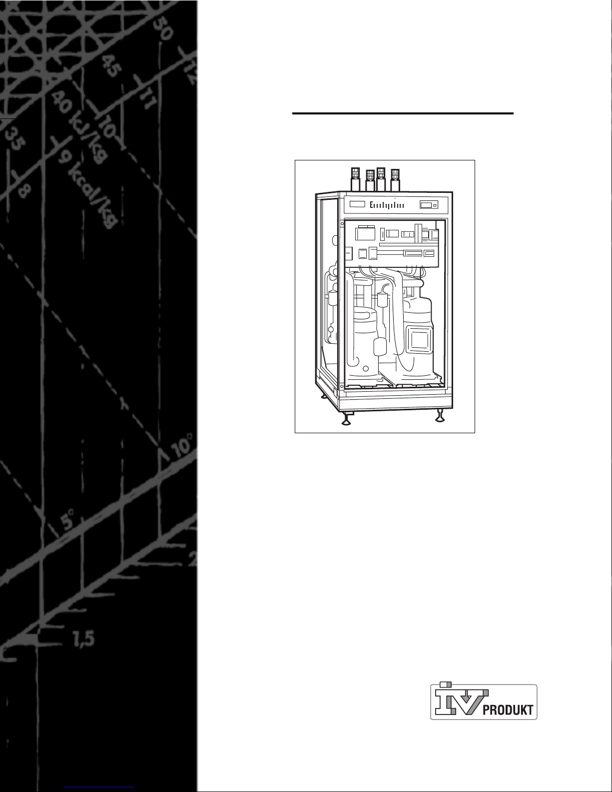
Cooling Unit for Producing Chilled Water
Envicooler
®
Operation and Maintenance Instructions

Address and telephone list for calling for service
Supplier:
IV Produkt
Box 3103
SE-350 43 VÄXJÖ, Sweden
Street address: Sjöuddevägen 7
Phone: +46 (0)470-75 88 00
Telefax: +46 (0)470-75 88 77
Seller: .......................................................................... Service: ........................................................................
Post address: .............................................................. Post address: ...............................................................
Telephone: ................................................................... Telephone: ...................................................................
Other: ...................................................................................................................................................................
..............................................................................................................................................................................
..............................................................................................................................................................................
..............................................................................................................................................................................
..............................................................................................................................................................................
..............................................................................................................................................................................
..............................................................................................................................................................................
..............................................................................................................................................................................
..............................................................................................................................................................................
System Data
Type of unit: .................................................................
Order number: .............................................................
Year manufactured: .....................................................
Supply voltage: ............................................................
Refrigerant: .................................................................
SAQ approved HP: ......................................................
Hydrostatic test: ..........................................................

Operation and Maintenance Instructions
Envicooler
2001-03-09 Pa
g
e 3
Air handling with the focus on LCC
Contents
1. The Cooling and Heat Pump System _______________________________________ 4
1.1 General ____________________________________________________________ 4
1.2 How the Cooling Circuit Works ________________________________________ 4
1.3 How the Controller Works _____________________________________________ 4
2. Summary of Specific Rules in the Refrigerant Act____________________________ 6
2.1 One-piece Units containing less than 3 kg of Refrigerant ___________________ 6
2.2 One-piece Units containing more than 3 kg of Refrigerant __________________ 6
2.3 One-piece Units containing a total of more than 10 kg of Refrigerant _________ 6
3. Operating Instructions for Components and Assembled Equipment ____________ 7
3.1 Regulations for Commissioning ________________________________________ 7
3.2 Checklist ___________________________________________________________ 8
4.Maintenance Instructions and Procedures __________________________________ 9
4.1 General ____________________________________________________________ 9
4.2 Requirements by Authorities according to the Refrigerant Act ______________ 9
4.3 Periodic Inspection __________________________________________________ 9
5. Fault Tracing and Searching for Leakage __________________________________ 10
5.1 Fault-tracing Schedule ______________________________________________ 10
5.2 Searching for Leakage_______________________________________________ 11
6. Flow Diagram for the Refrigerant System__________________________________ 12
7. Technical Specification_________________________________________________ 13
8. Appendices
8:1 Pressure and Tightness Tests - Refrigerant Circuit
8:2 Safety Equipment
8:3 Commissioning Report
8:4 Pressure and Tightness Tests - Liquid Circuits

Pa
g
e 4
Operation and Maintenance Instructions
Envicooler
2001-03-09
Air handling with the focus on LCC
1. The Cooling and Heat Pump System
1.1 General
All cooling and heat pump systems operate according to the same principle. The system moves the heat content in a medium, such as air, water, gas, etc. from one space
where the heat isn’t wanted or needed, to another place where it is possible to utilise
the heat, or
g
et rid of it.
Your system
has been designed and installed to meet given performance requirements. We’ve selected and combined special components to meet these requirements with optimum safety and at lowest possible total cost.
We’ve desi
g
ned the system according to specific fundamental prerequisites, which
must exist for it to operate. These prerequisites should not be altered without first
checking that the system can cope with this change.
1.2 How the Cooling Circuit Works
See the flow diagram.
The refri
g
erant in the cooling circuit absorbs heat from the component being chilled
while it passes through the evaporator. As its pressure drops, the refrigerant evaporates and transforms from liquid to gas.
The cold suction
g
as that now has absorbed heat from the cooled space/medium is
sucked back into the compressor where it is compressed and heats up.
In all fully hermetic compressors, the suction
g
as is also used to cool the electric motor that drives the compressor. The refrigerant now contains heat from the component
bein
g
chilled, heat from the compressor motor and heat generated by compression.
The refrigerant is in the form of hot gas when it leaves the compressor and circulates
to the condenser where it
g
ives off its heat.
The refrigerant then condenses as it cools, transforming from gas to liquid. This occurs repeatedly in a totally closed system, until the temperature in the chilled/heated
medium drops/rises to its set point.
1.3 How the Controller Works
1.3.1 Interlocking
EVC is interlocked across an external start si
g
nal.
1.3.2 Operation
The selector switch S1 is used for initiatin
g
start-up (yellow LED is lit). When the temperature at the heating medium sensor drops below the preset value, a signal is transmitted across the stepping switch to start the compressors in a preset starting order
so as to maintain the preset temperature. The in-operation condition of each compressor is indicated across the steppin
g
switch. Output terminal blocks are provided
for in-operation indication.
Operation and Maintenance Instructions
Envicooler
2001-03-09 Pa
g
e 5
Air handling with the focus on LCC
1.3.3 Compressor Protection
If the safety circuit alarm trips the compressor will stop and a red LED will li
g
ht up. A
flow monitor supervises the water flow in the cooling medium circuit. On insufficient
flow the monitor stops the compressors and initiates an alarm across a stepping
switch. The flow monitor alarm can be reset by settin
g
the selector switch S1 in the 0
position. The safety circuit alarm will trip if any of the following four conditions arises:
• Hi
g
h pressure in the system, HP
• Low pressure in the system, LP
• Tripped protective motor switch Q
• Tripped thermocouple in the compressor
The
g
roup alarm safety circuit has output terminal blocks. If the safety circuit alarm
trips repeatedly,
g
et in touch with an authorised refrigeration service company.
1.3.4 Technical Description
The compressor power cubicle of the EVC unit contains the followin
g
:
• Main switch
• Protective motor switch
• Contactors
• Auxiliary relays
• Controller
• Selector switch
• Flow monitor
The cubicle is mounted inside the EVC unit and has been internally prewired and
tested at the factory.
L1 L2 L3 N PE
Power supply
3*x 400 V + N 50 Hz
Size Rec. fuse Rec. cable section
EVC-1610
EVC-2410
EVC-3110
EVC-4020
EVC-4820
EVC-6220
EVC-7830
EVC-9330
20 AT
25 AT
35 AT
50 AT
50 AT
63 AT
80 AT
100 AT
4 mm
2
6 mm
2
10 mm
2
16 mm
2
16 mm
2
25 mm
2
35 mm
2
50 mm
2
Envicooler
251 252
External start signal
Potential-free, NO
253 254
Group alarm
Potential-free, NO
C1 C2 C3 C4
((!))
SET
AL
prg
o
C
XC440C
Dixell
1
2
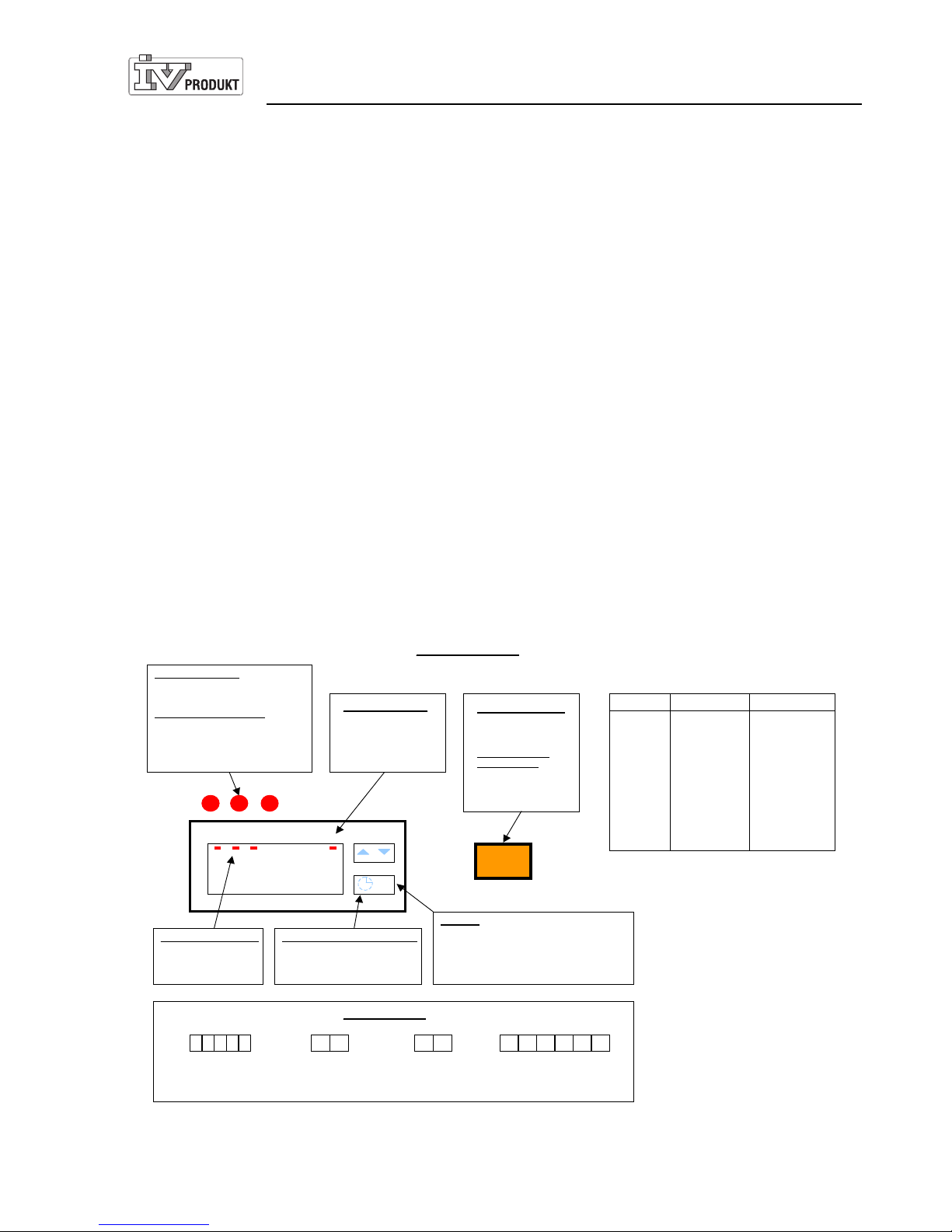
Set point
To show the set point
: press the SET key.
To change the set point
: press the SET key for
at least 2 sec. Alter the setting by pressing the
arrow up or arrow down key. Then press the
SET k ey to save your setting.
Running period – compressors
Press and hold the clock button
for at least 3 sec. Shows the running period of each compressor.
Flow monitor alarm
If a buzzer sounds and a
red LED is lit, the flow
monitor alarm has
tripped.
In-ope ratio n indica tion
A red LED indicates that
the compressors are
running.
Input cables
EVC Selector switch
O
= EV C sw itched o ff
I
= EVC start mode
To re set the flow
monitor alarm
Press the switch to O;
then pres s it to Iagain.
Safety circuit alarm
If a red LED is lit, the safet y circu it of
the relevant compressor has tripped.
To re set the sa fety c ircuit
Press the reset button on the high
pressure switch or low pressure
switch. Reset the protective motor
switch
.
I O
255 256
In-operatio n indication
C1, C2, C3
Potential-free, NO
257 258 259 260
LJ 990520
*) If the order of phases is wrong, the machine will run unusually loud.
 Loading...