

iVigil IP6D31, IP3H00, IP4831E User Manual
- 1 -
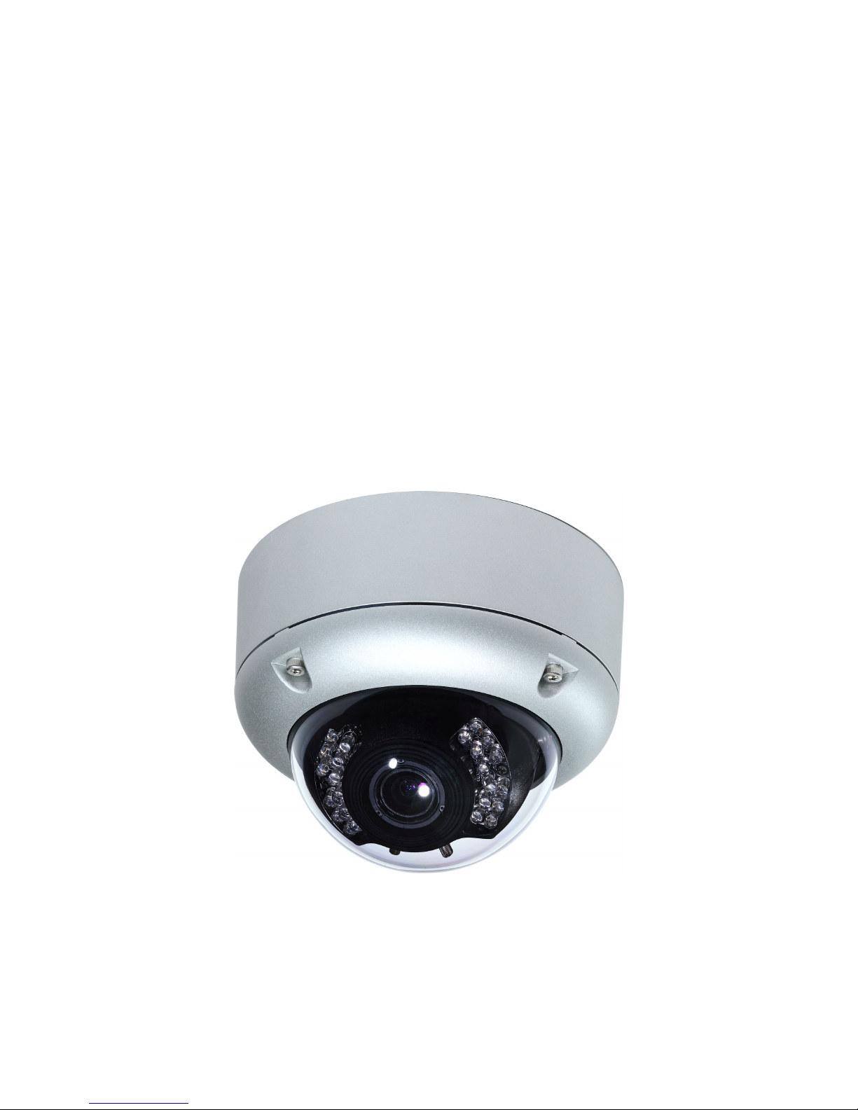
3M D&N Auto-Iris WDR
Vandal Auto-Iris Outdoor
IR Dome IP Camera
User Manual
- 2 -
CAUTION
RISK OF ELECTRIC SHOCK.
DO NOT OPEN!
CAUTION :
TO REDUCE THE RISK OF ELECTRICAL SHOCK,
DO NOT OPEN COVERS (OR BACK).
NO USER SERVICEABLE PARTS INSIDE.
REFER SERVICING TO QUALIFIED
SERVICE PERSONNEL.
WARNING: This symbol is intended to alert the user to the presence of un-insulated “dangerous
voltage”.
CAUTION: This symbol is intended to alert the user to presence of important operating and
maintenance (Servicing) instructions in the literature accompanying the appliance.
Disposal of Old Electrical & Electronic Equipment (Applicable in the European Union and
other European countries with separate collection systems).\
This symbol on the product or on its packaging indicates that this product shall not be treated as
household waste. Instead it shall be handed over to the applicable collection point for the recycling of
electrical and electronic equipment. By ensuring this product is disposed of correctly, you will help
prevent potential negative consequences for the environment and human health, which could otherwise
be caused by inappropriate waste handling of this product. The recycling of materials will help to
conserve natural resources. For more detailed information about recycling of this product, please
contact your local city office, your household waste disposal service or the shop where you purchased
the product. The power cord is the main power connection. Therefore, constantly plug and unplug of
the power cord might result in malfunction of the product.
CE / FCC Mark.
This apparatus is manufactured to comply with radio interference requirement.
Do not install the product in an environment where the humidity is high.
Unless the product is waterproof or weatherproof, otherwise it can cause the image quality to be
poor.
Do not drop the product or subject them to physical shocks.
Except for vandal-proof or shockproof product, otherwise it will result malfunctions to occur.
Never keep the product to direct strong light.
It can damage the product.
Do not spill liquid of any kind on the product.
If it gets wet, wipe it dry immediately. Alcohol or beverage can contain minerals that corrode the
electronic components.
Do not expose to extreme temperatures.
Use the product at temperatures within 0
℃℃℃℃
~ 50
℃℃℃℃
.
It is advised to read the Safety Precaution Guide through carefully before
operating the product, prevent any possible danger.

- 3 -
Table of Contents
Physical Description..................................................................................................... - 5 -
Quick Installation......................................................................................................... - 7 -
Software Installation ...................................................................................................- 11 -
1. User Login............................................................................................................... - 14 -
2. Live View Page........................................................................................................ - 15 -
2.1 Video Type............................................................................................................. - 15 -
2.2 Source .................................................................................................................... - 15 -
2.3 Protocol Type ........................................................................................................ - 15 -
2.4 Utility ..................................................................................................................... - 16 -
2.5 Light Status ......................................................................................................... - 17 -
3. Setting...................................................................................................................... - 18 -
3.1 Network Setting .................................................................................................... - 19 -
3.1.1 Basic Setting....................................................................................................... - 19 -
3.1.2 Advanced Setting ............................................................................................... - 20 -
3.1.3 Service Setting ................................................................................................... - 22 -
3.2 Camera Setting ..................................................................................................... - 29 -
3.2.1 Camera Setting .................................................................................................. - 29 -
3.2.2 Streaming Setting .............................................................................................. - 35 -
3.2.3 Event Record ..................................................................................................... - 37 -
3.3 Alarm ..................................................................................................................... - 38 -
3.4 User Management................................................................................................. - 39 -
3.5 Backup Device ...................................................................................................... - 40 -
3.6 System.................................................................................................................... - 42 -
3.6.1 Basic Setting....................................................................................................... - 42 -
3.6.2 Advanced Setting ............................................................................................... - 42 -
3.6.3 Time Setting ....................................................................................................... - 44 -
3.6.4 DST (Daylight Saving Time)............................................................................. - 45 -
Appendix A – Upgrade Firmware at Local Device ................................................. - 46 -
Appendix B – iPhone 3GPP View ...............................................
錯誤! 尚未定義書籤。
Appendix C – Android Phone 3GPP View.................................
錯誤! 尚未定義書籤。
Appendix D – Specifications...................................................................................... - 47 -

- 4 -
Product Feature
3 Megapixel image; resolution is up 2048x1536.
Support True WDR image processing.
Support H.264 / MJPEG codec, video quality is adjustable, video type can be divided into
H.264_1、H.264_2(3GPP) and MJPEG
Support G.711 codec, two ways audio is supported.
Support high performance network transmission algorism, provide low-latency video and
audio stream.
Support event and schedule recording.
Support multiple events search (alarm and motion) for basic and intelligent playback.
(Function is provided by bundle software)
Support motion detection; detection area and sensitivity are adjustable.
Support multiple alarm and event trigger.
Video stream bit rate, frame rate and resolution are adjustable.
Multi-language supported.
Support multi-level password and protection in order to provide the highest security.
Support Micro SD Card, for pre-event and post-event recording image data, support for
remote backup video files.
Support remote setup, live view, recording, snapshot, ftp and firmware upgrade by web page
or bundled software.
Provide SecuUtility for searching and network setting up supportive device in LAN.
Network protocol supported: HTTP, UPnP, DNS, DDNS, RTSP, RTP, RTCP, RTSP over
HTTP, TCP/IP, UDP/IP, ICMP, DHCP, PPPoE, FTP, NTP, SMTP, Bonjour, Multi-Casting.
Support auto re-connecting after network or power shortage.
Free bundle 32 channel surveillance software. Support maximum 32 channels live view and
16 channels playback simultaneously.
- 5 -
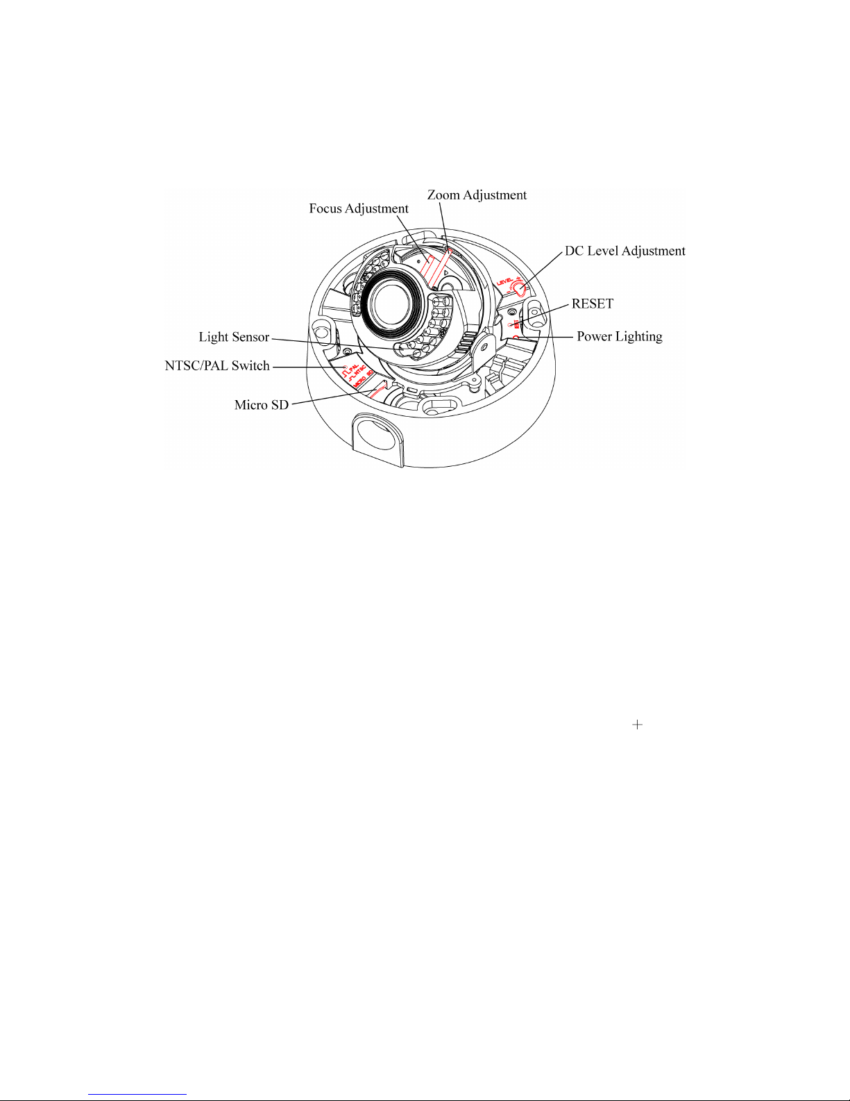
Physical Description
Inside Overlook
Focus Adjustment
Adjust for focal length, and take a clear image.
Zoom Adjustment
Zoom image size, and adjust the width of the image.
Light Sensor
Detect incoming light sensor. While the incoming light is too low, image will display in
monochrome automatically.
NTSC/ PAL Switch
When the button is pressed, the camera switched to the NTSC video output;
on the contrary, the camera switched to PAL video output.
Micro SD
Support Micro SD card, the maximal capacity could be up to 32 GB. Device doesn’t support
Micro SD hot swapping, please reboot system after insert or remove Micro SD card.
DC Level Adjustment
DC Level adjustment knob is used to adjust the aperture size of the level; to + (clockwise)
direction to adjust the aperture becomes large, to — (counterclockwise) direction to adjust
the aperture becomes small. The adjustment needs 2-3 seconds to take effective, so please
wait for aperture stable until next adjustment.
RESET
When system is frozen, please press the reset button and keep it depressed for 5 seconds,
after the power light is blinking, then release the reset button, the system will finish
rebooting procedure in one minute. When the power light is on; the device is booted up
successfully.
Power Lighting
When power lighting on means device boots up successfully; power lighting off means there
is no power input. When power lighting blinking means device operation system is being
loaded or hardware resets.

- 6 -
Exterior View
Power Connector
Connect to 12V DC/24V AC power adapter.
Ethernet
Connect to Ethernet network.
Alarm In/Out
To connect external alarm I/O devices, please refer to below for Alarm I/O pin definition.
GND Sensor IN ALR N.O ALR COM
GND: ground wire.
Sensor IN: connect to alarm in device.
ALR N.O: connect to N.O(normal open) alarm out device.
ALR COM: connect point that corresponds to alarm in.
Line-In (Pink)
Slot for audio in connector.
Line-Out (Green)
Slot for audio out connector.
RS485
The function is retained, pin defined as follows:
D+ D-
Video Out
Slot for video out connector.
- 7 -
Quick Installation
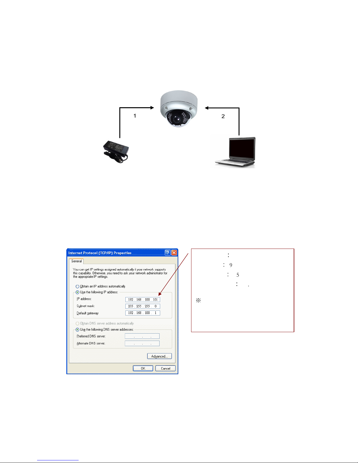
Basic Connection
(1) Connect the 12V DC adaptor to the power jack of the IP camera.
(2) Use Ethernet cable to make connection from the Ethernet 10/100 RJ45 socket of IP camera
to the PC.
Network Setting
After completing the basic hardware connection, make sure that the PC and the IP camera IP
address are both in the same network segment. Example: Setup preset IP camera IP to
192.168.100.100 and configure your PC IP address as the figure description below.
Setup format:
IP Address:192.168.100.xxx
Subnet Mask:255.255.255.0
Default Gateway:192.168.100.1
※
Note
xxx address ranges from 1~254, please
avoid using “100” which has been used
by IP camera.
- 8 -
SecuUtility
(1) Please install SecuUtility from the product CD. (Please refer to chapter 3.3.1 for installation
procedures.)
(2) Start SecuUtility.
(3) After starting SecuUtility, the program will automatically search and display supportive
devices in local LAN.
(4) Choose which device you would like to access, the default IP address on the device is
192.168.100.100
(5) Double click on the IP address, will automatically open the selected device web image.
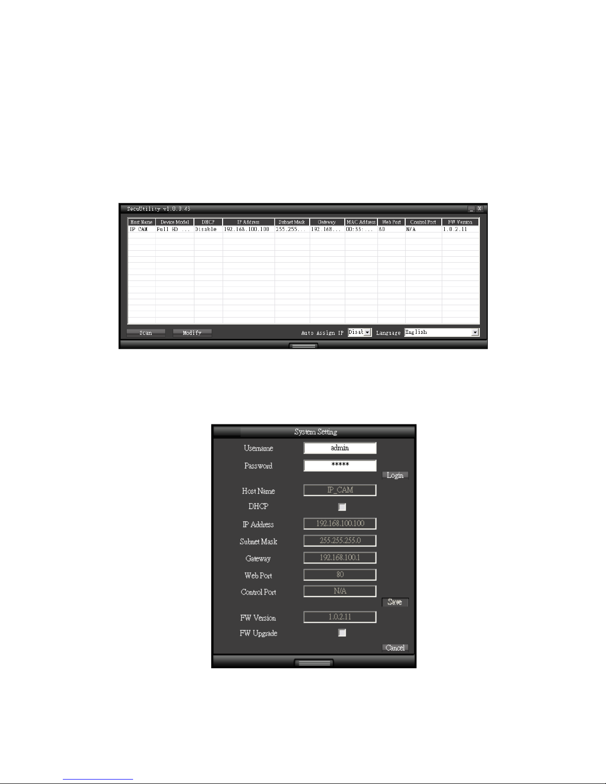
(6) Please select on the device you would like to modify its setting and click “Modify”.

- 9 -
Please fill in username and password. (Default username and password is admin/
admin)
User can manually modify system setting: connection type and web port. Please
click “Save” button before complete change.
SecuUtility provides firmware upgrade, please click on firmware upgrade checkbox,
and select new firmware (.img) in pop-up window. System will automatically start
firmware upgrade.
Above system setting function only works in firmware version is later than V1.x.x.x. If the
firmware version of the device is not supportive, please notify your system administrator
for firmware upgrade.
(7) Click “Scan” to refresh searching supportive devices in local LAN.
(8) If there is no DHCP server in local LAN, SucuUtility can automatically assign IP address for
connected network device. When SecuUtility searches network device which IP address is
192.168.100.100 in LAN, system will automatically assign an IP address of which is the same
network segment as client PC. To enable this function, please “Enable” on Auto Assign IP
item. Please notice that DO NOT enable this function when there is already a DHCP server in
LAN in case of IP conflict issues.
Device Login
Once you have logged in, you will see a pop-up information bar requiring your attention for
installing ActiveX Control, use mouse right click to install ActiveX control.
Then a window will appear asking you to confirm whether or not you want to install the ActiveX
control. Select “Install”.
- 10 -
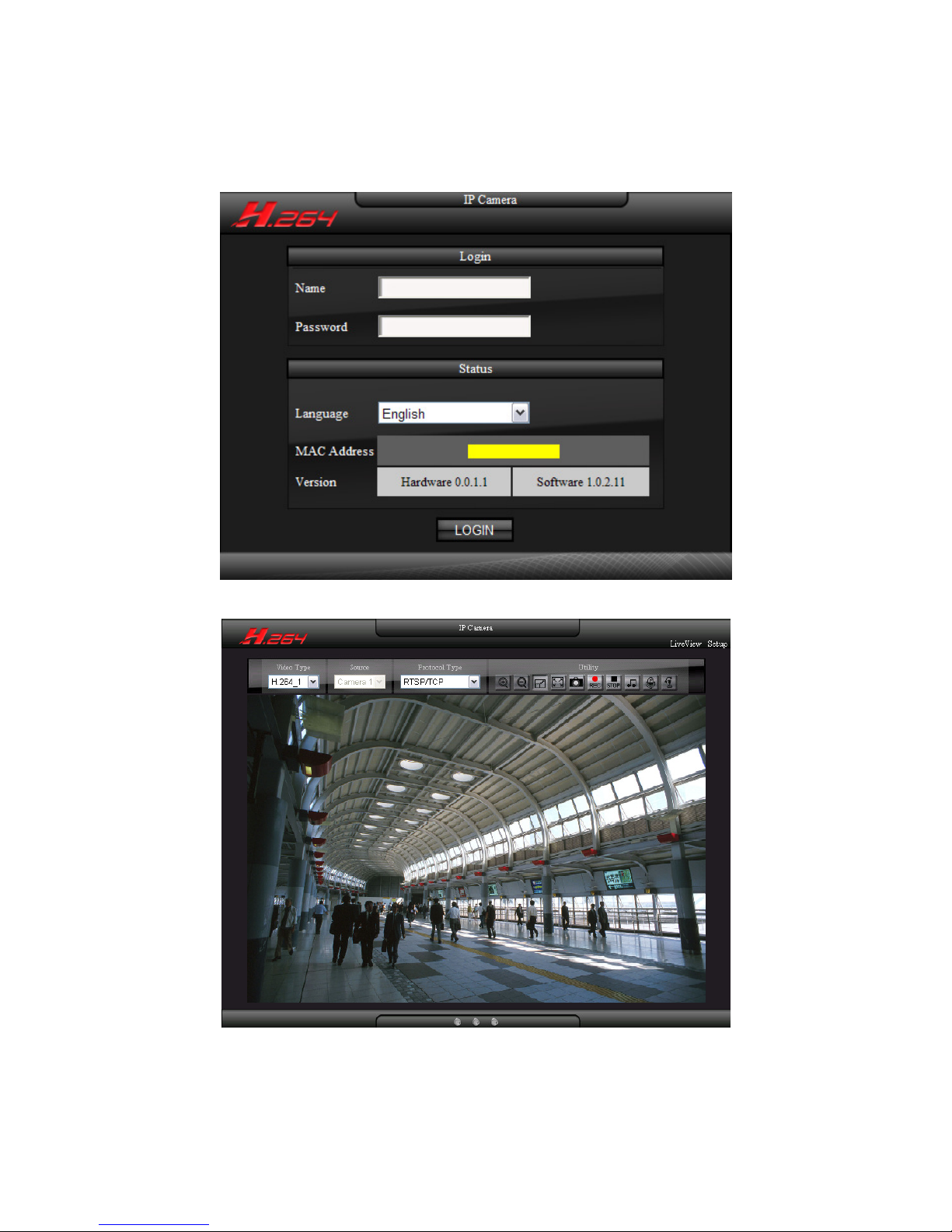
After Active control has been successfully installed, website login page appears on the screen.
Login device with default username and password: admin / admin.
Live view image after successfully login.
If user cannot see video stream with H.264 format, please install FFDshow decode software
from installation CD.
- 11 -
Software Installation
Please install following software from installation CD.
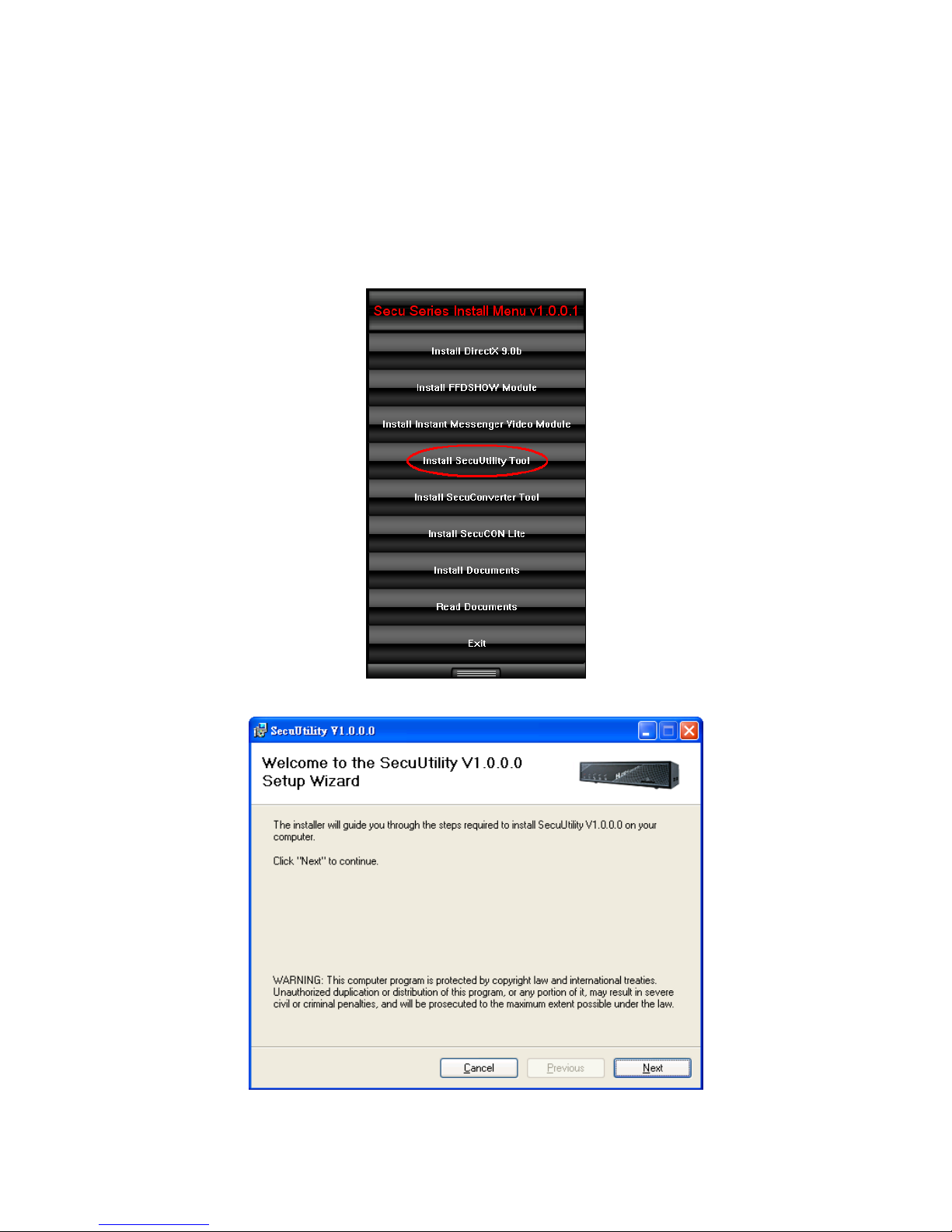
Install SecuUtility
(1) Click Install SecuUtility Tool
(2) Click Next.
- 12 -
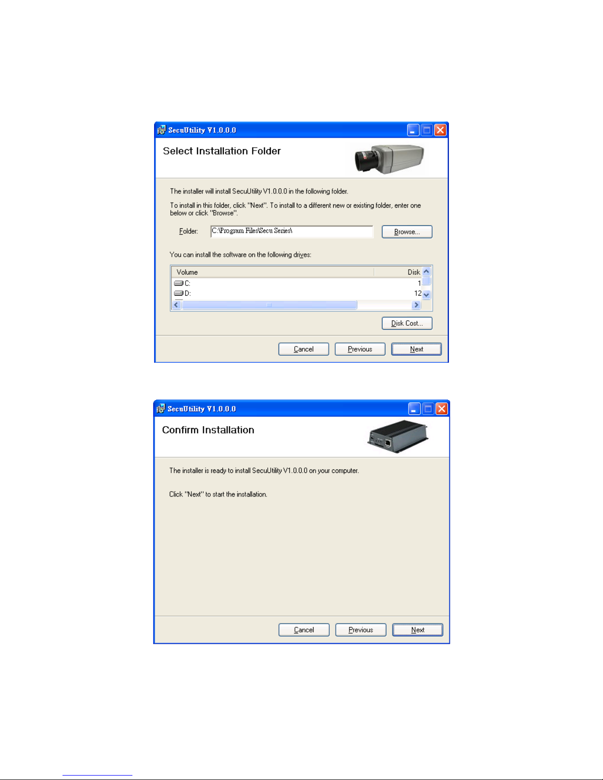
(3) Select Installation Folder.
(4) Confirm Installation, please click Next.
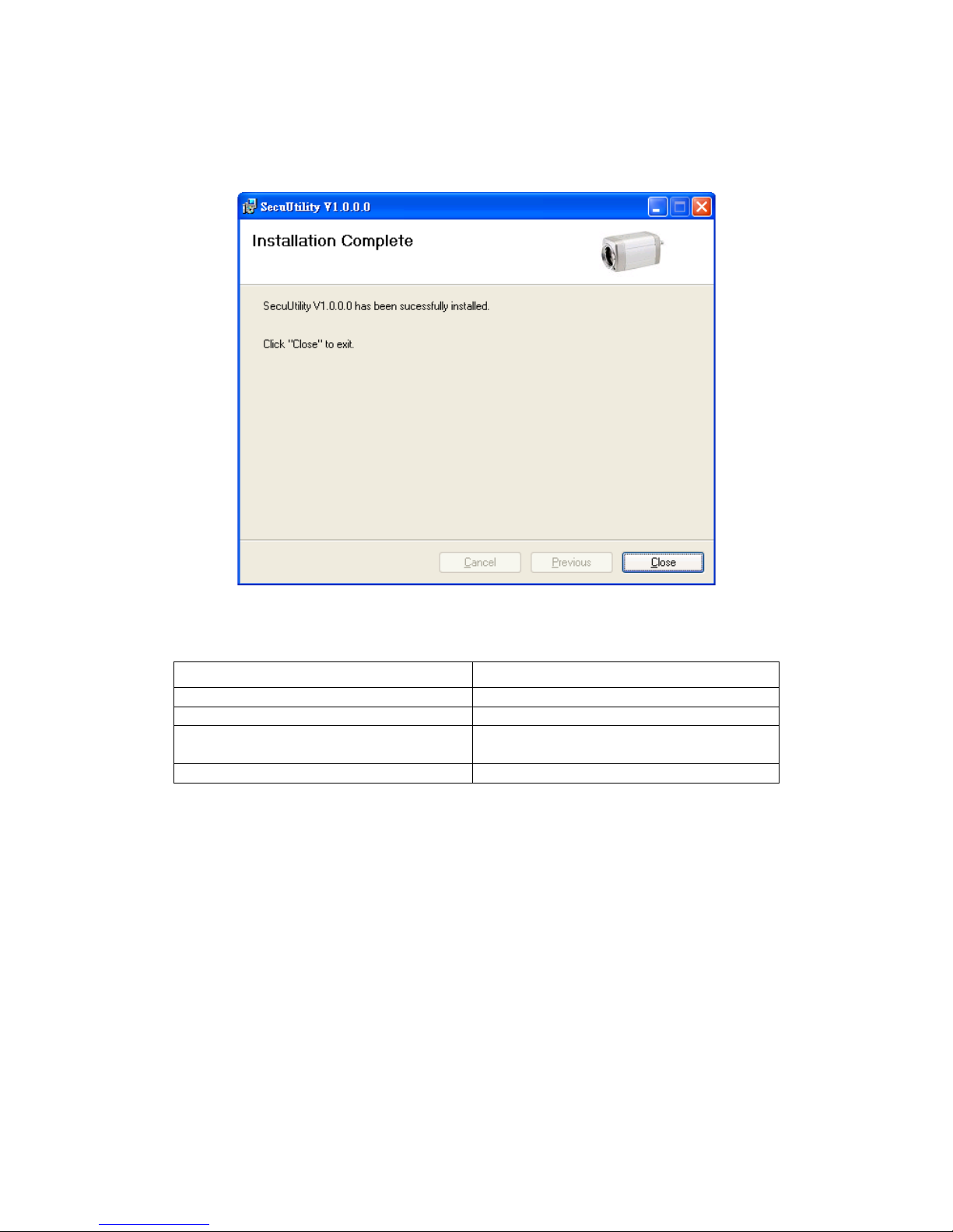
- 13 -
(5) Installation complete, please click Close to exit.
Recommended Computer Equipment
CPU Intel® Core 2 Due E7200 or above
RAM 1GB or above
Audio Card Needed
Operation System
Windows 2000, Windows XP SP2 and
above, Windows Vista, Windows 7
Browser IE6 SP2 and above
- 14 -
System Configuration
1. User Login
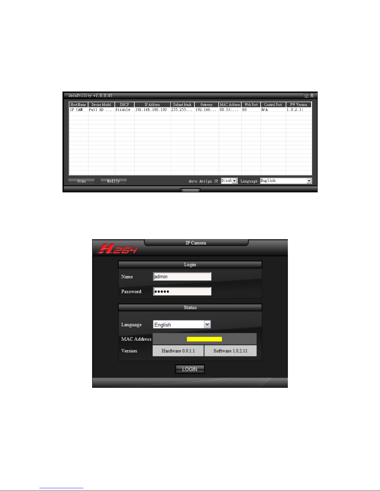
One minute after the device is powered on, please start SecuUtility. The program will
automatically search and display supportive devices in local LAN. Please click on the device you
would like to access, and then enter login page of the device.
Login device with default username and password: admin / admin.
User can switch to preferred language to login system. Also, device information such as MAC
address and hardware and software version, displays in login page.

- 15 -
2. Live View Page
2.1 Video Type
Video type can be divided into H.264_1、H.264_2(3GPP) and MJPEG.
2.2 Source
Device receive single camera source. This item is unchangeable.
2.3 Protocol Type
Select image streaming transmission protocol.
RTSP/ TCP
Choose this item while the network is under low bandwidth. Video and audio streaming
transmits through network TCP layer.
RTSP/ UDP
Choose this item to get smooth live streaming. Video and audio streaming transmits
through network UDP layer.
※※※※
NOTE:
(1) When the network environment is not in LAN, please choose RTSP/TCP protocol type to
obtain image.
(2) RTSP / UDP protocol is not applicable for different network segments.
RTSP over HTTP
Video and audio streaming transmits through network TCP layer via HTTP port.
- 16 -
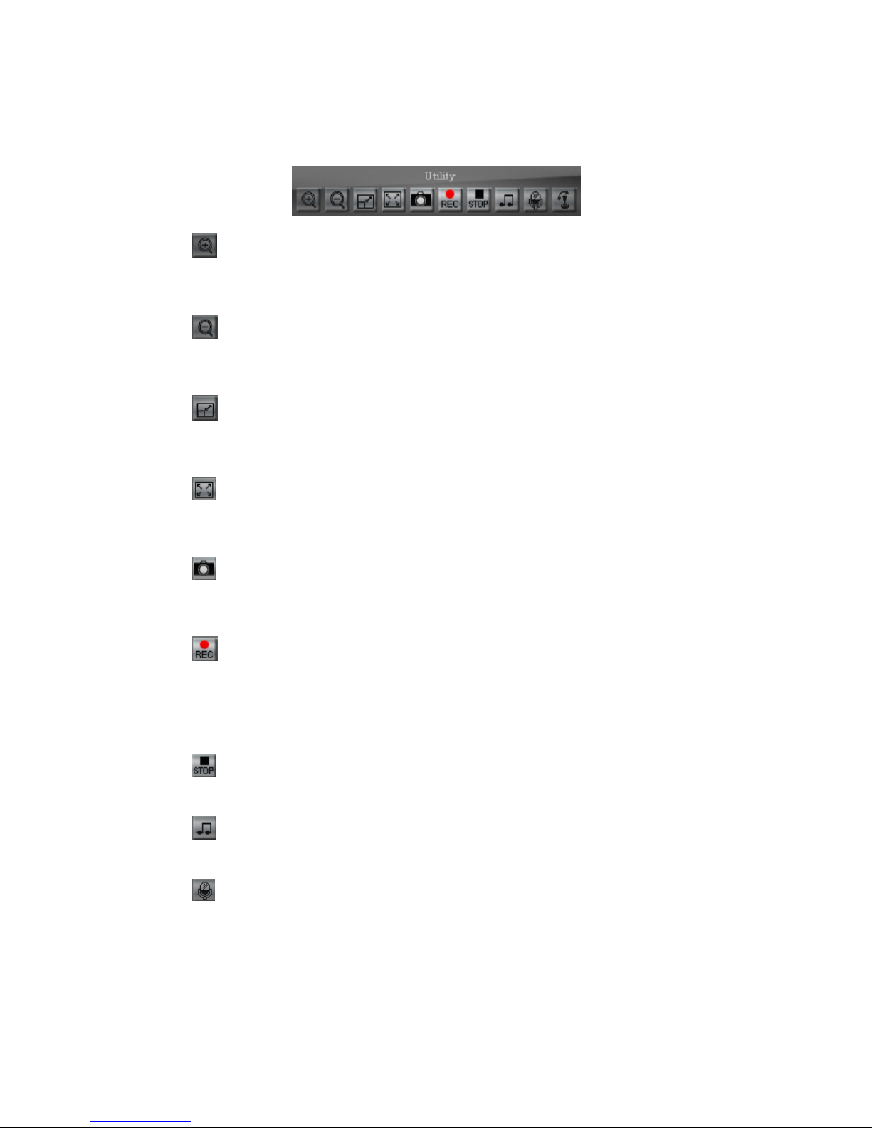
2.4 Utility
Zoom In
Click on the button to zoom in image. Image can zoom 8 times for maximum. To return
back to normal image size, please click on zoom out button.
Zoom Out
Click on the button to zoom out image. The button has no effect when the image has
back to original size.
Stretch
When image resolution greater than 720x480, click on the icon to adjust image size to
720x480. To return back original size, please click on the button again.
Full Screen
Click on the button or double click on the image, the full screen mode will be activated.
Double click on the image can return to standard mode.
Snapshot
Click on the button, the image will be snapshoot, all image taken will be stored in
default path., regarding the default path, please see chapter 3.6.2. (Advanced setting)
Recording
Click on the button to start recording. Record file will be stored in default path.
Regarding the default path, please see chapter3.6.2. (Advanced setting) Recording file
is cut every 5 minutes; when the remaining space is less than 1GB or system setting is
changed, recording will automatically stop.
Stop Recording
Click on the button to stop recording.
Audio
Click on the button to play audio; click again to stop playing.
Broadcast
Click on the button to start broadcast, click again to stop broadcasting.
- 17 -
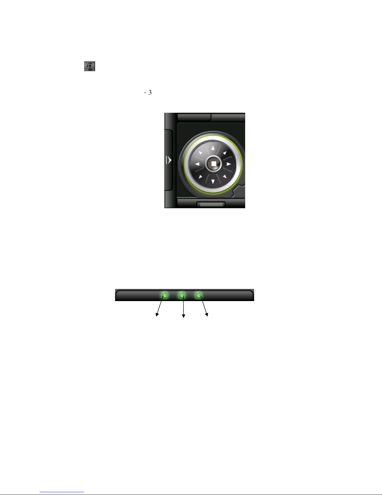
PTZ
Click on the button to start PTZ control panel, click again to hide the panel. Before
operating this panel, please make sure that the DigitalZoom function is enabled; please
refer to chapter 3.1.3、3.2.1 for detail. Right-click on the control panel to display quick
menu, select the digital zoom mode for control image direction.
Direction Control
Control the angles and direction of camera, with up, down, left, right, up left, up right, down
left, and down right. Press a direction button; camera will rotate in this direction until
releasing the button. The middle button is for back to home.
2.5 Light Status
The lights from left to right are recording, audio and broadcast function status.
(1) Recording Status
It is off by default, click on recording button, light will keep flashing; click on stop
recording button, light will be off.
(2) Audio Status
It is off by default; click on audio button to enable audio function, light will keep
flashing; click on the audio button again, light will be off.
(3) Boradcast Status
It is off by default; click on broadcast button to enable broadcast function, light will
keep flashing; click on the broadcast button again, light will be off.
(1)
(2)
(3)
- 18 -
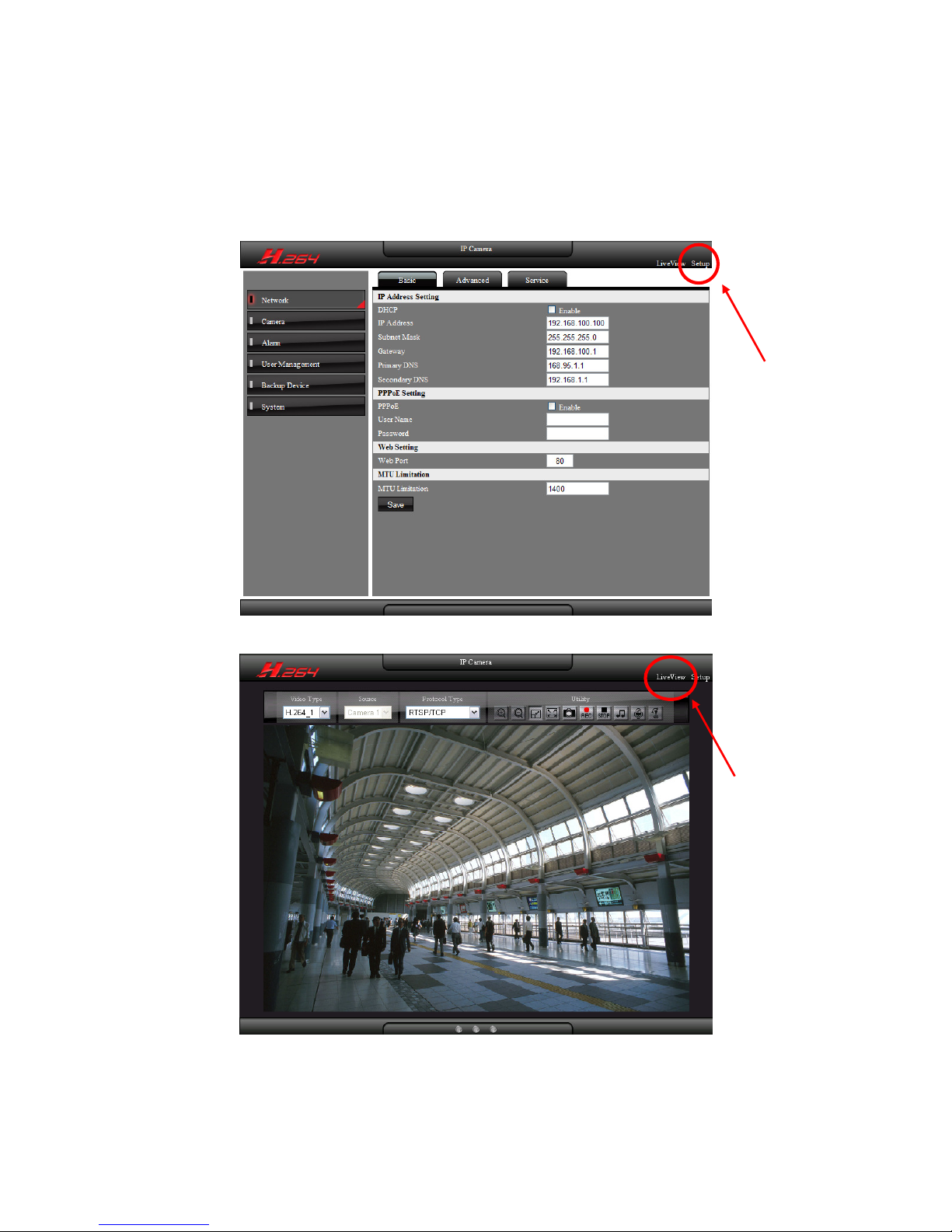
3. Setting
Click on Setting” on the top right corner of the web page to configure the device, click on
“LiveView” to return back to live view image.
Click Setup
Click LiveView
- 19 -
3.1 Network Setting
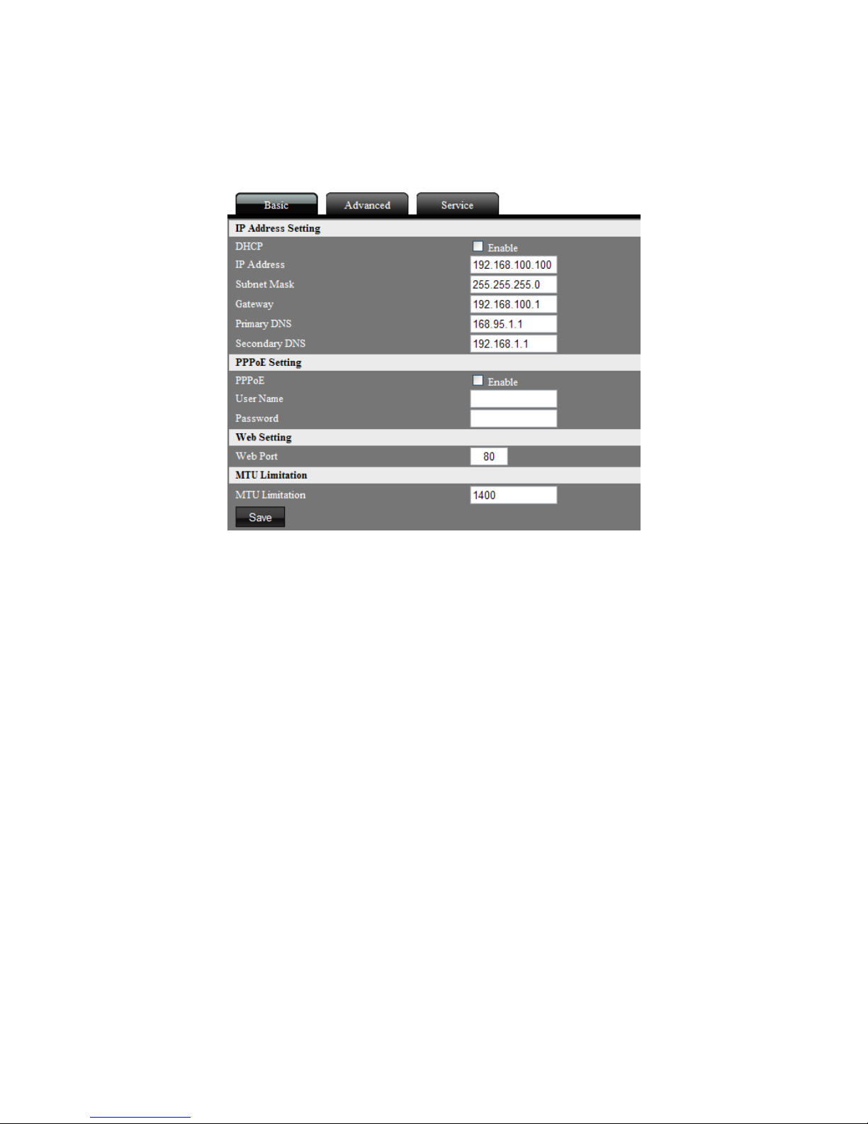
3.1.1 Basic Setting
IP Address Setting
User can setup device IP address.
DHCP
Click on enable to activate DHCP; the device will get IP address from DHCP server.
IP Address
Enter IP address for the device.
Subnet Mask
Enter a subnet mask of the device, If IP address of this device is changed, adjust the
subnet mask accordingly.
Gateway
Enter the IP address of the gateway (the router).
Primary DNS
Define the primary DNS server IP address. This is used for identifying this device by
name instead of IP address.
Secondary DNS
The IP address of the secondary DNS server; it will be used once the primary DNS server
fails.
PPPoE Setting
Connect the device to internet by PPPoE through ISP.
PPPoE
Click on enable to activate PPPoE function.
User Name
Enter the user name of the ISP account.
Password
Enter the password of the ISP account.
- 20 -
Web Port Setting
Setup device web port number, default is 80. To change to another port number, take 8080
for instance, set hyperlink format as below:
http://192.168.100.100:8080
Do not duplicate web port with advanced ports. Recommended setting range is from 1000 to
65535.
MTU
MTU, Maximum Transmission Unit, is the value that transmitting package that can pass
through network protocol. Set this value to prevent data unable to deliver during cross
network domain or insufficient bandwidth environment.
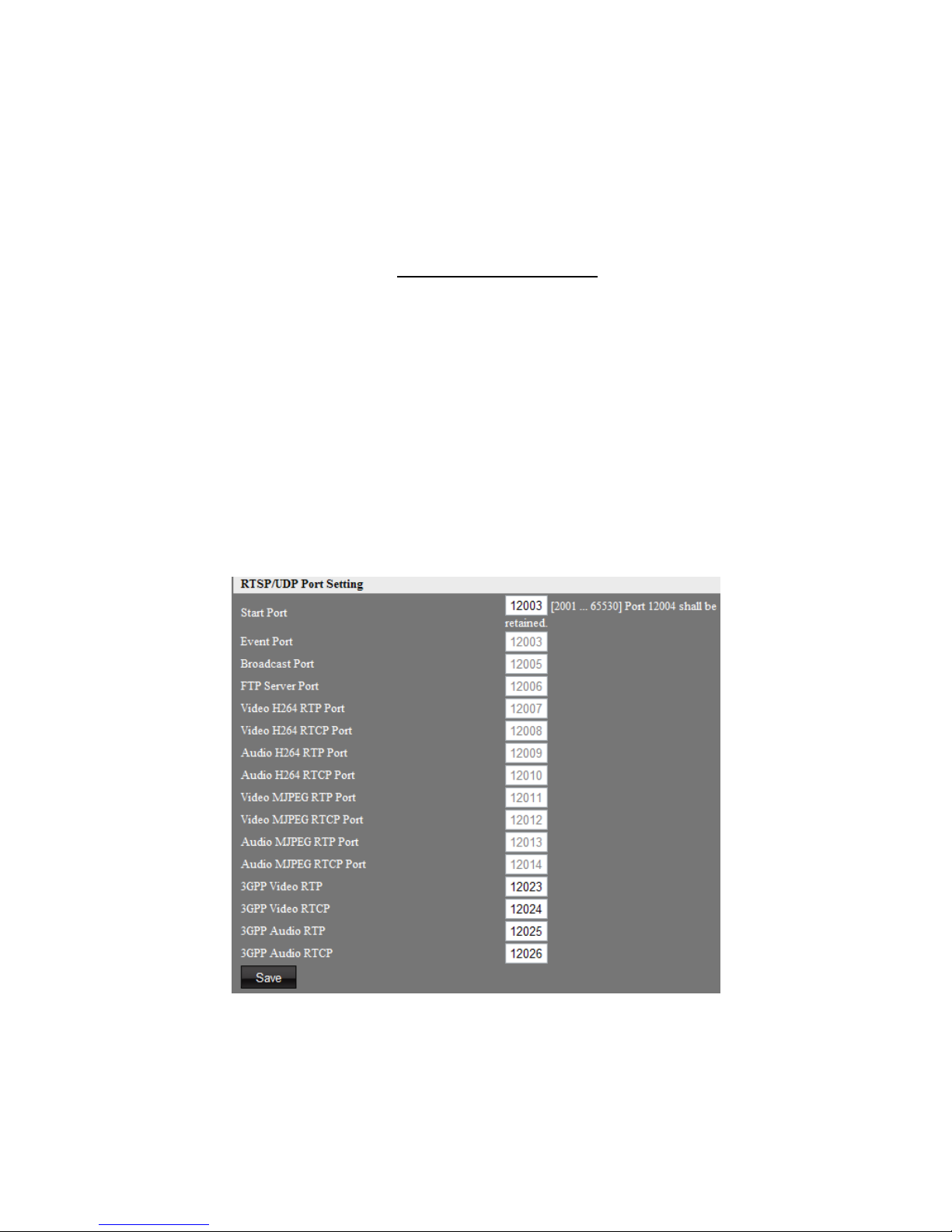
3.1.2 Advanced Setting
When image protocol type is set as RTSP/ UDP, below advanced ports will use to transmit video
and audio streaming.
Start Port
Define the RTSP/UDP ports segment of the device. Setting range starts from 2001 to 65530.
Port 12004 shall be retained. RTSP/UDP ports only set as continuous port numbers. Except
start port and 3GPP serial ports, the other ports are set automatically by system.
 Loading...