

Page 1
arrowhead within a triangle is
RISK OF ELECTRIC SHOCK
TO REDUCE THE RISK OF ELECTRICAL
SHOCK DO NOT REMOVE COVER NO
PARTS INSIDE.
REFER SERVICING TO QUALIFIED
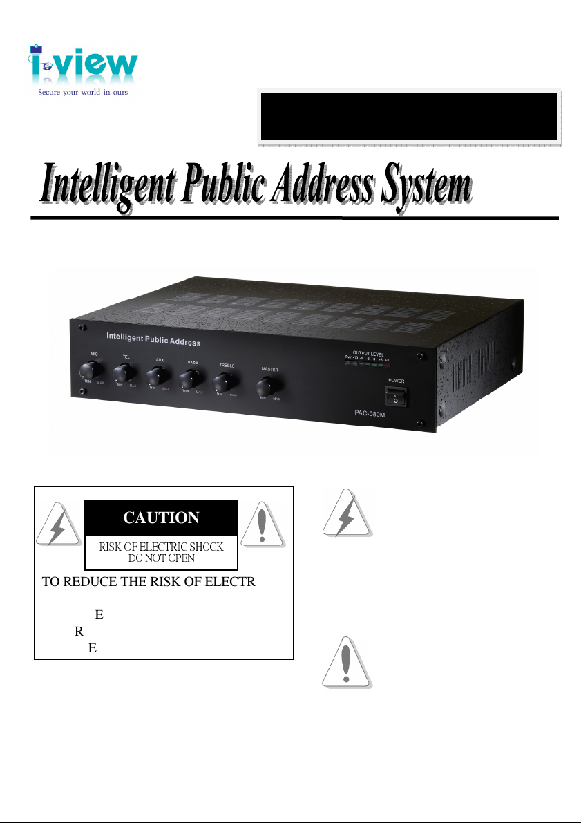
Operating Instructions
CAUTION
USER SERVICEABLE
SERVICE PERSONNEL
Version: V1.01
Doc. No: 2011040801
PAC-080M
The lighting flash with
intended to tell the user that
DO NOT OPEN
parts inside the product are a
risk of electric shock to
persons
The exclamation point within a
triangle is intended to tell the
user that important operating
and servicing instructions are
the papers with the appliance.
Page 2

Table of Contents
About This Guide ------------------------------------------------------------------------------------------------- 3
Customer Support ------------------------------------------------------------------------------------------------ 3
FCC Compliance Statement ------------------------------------------------------------------------------------ 4
FCC Warning ------------------------------------------------------------------------------------------------------ 4
Trademark ---------------------------------------------------------------------------------------------------------- 4
Chapter 1. General Description -------------------------------------------------------------------------------- 5
1-1. Product Features --------------------------------------------------------------------------------- 5
1-2. Product Specification --------------------------------------------------------------------------- 6
1-3. Packing Checklist ------------------------------------------------------------------------------- 6
Chapter 2. General Installation -------------------------------------------------------------------------------- 7
2-1. General Installation------------------------------------------------------------------------------ 7
2-2. Nomenclature Description --------------------------------------------------------------------- 8
2-3. Operation --------------------------------------------------------------------------------------- 12
2
Page 3

About This Guide
Please follow the instructions in this manual to obtain the optimum results from this unit.
We also recommend that you keep this manual handy for future reference.
Conventions used in this guide
To make sure that you perform certain tasks properly, take note of the following symbols to use throughout
this manual.
WARNING: Information to prevent injury to yourself when trying to complete a task.
CAUTION: Information to prevent damage to the components when trying to complete a task.
IMPORTANT: Information that you must follow to complete a task.
NOTE: Tips and additional information to aid in completing a task.
Customer Support
If technical problems arise with the use of our products in which you and your vendor cannot resolve, please
try the following: If you have an Internet connection, visit the I-View website http://www.i-view.com.tw
(Taiwan) for any software or product updates, or email to support@i-view.com.tw (Taiwan) or Tel:
886-3-510-3001 Fax: 886-3-510-3002 (Taiwan). We are dedicated to providing the highest quality support.
E-mailing our tech support will give you the chance to document each of the above items in a very clear and
concise manner and will give our support team a chance to document any problems and respond with
thoroughly researched answers.
3
Page 4

FCC Compliance Statement
This device complies with part 15 of the FCC Rules. Operation is subject to the following two conditions:
This device may not cause harmful interference, and this device must accept any interference received,
including interference that may cause undesired operation.
FCC Warning
This equipment has been tested and found to comply with the limits for a Class B digital device, pursuant to
Part 15 of the FCC Rules. These limits are designed to provide reasonable protection against harmful
interference in a residential installation. This equipment generates uses and can radiate radio frequency
energy and, if not installed and used in accordance with the instructions, may cause harmful interference to
radio communications. However, there is no guarantee that interference will not occur in a particular
installation. If this equipment does cause harmful interference to radio or television reception, which can be
determined by turning the equipment off and on, the user is encouraged to try to correct the interference by
one or more of the following measures:
Reorient or relocate the receiving antenna.
Increase the separation between the equipment and receiver.
Connect the equipment into an outlet on a circuit different from that to which the receiver is connected.
Consult the dealer or an experienced radio/TV technician for help.
Shielded cables and I/O cords must be used for this equipment to comply with relevant FCC regulations.
Trademark
I-View, P.A. DVR, e-Witness, @-Witness Pro, u-Witness XP, x-Witness, FreeView Pro, AnyView Pro,
PDAVirw and MobileView are registered trademarks of I-View Communication Inc.
Microsoft, Windows 95, 98, ME, Windows2000, XP, Vista and 7 are registered trademarks of Microsoft
Corporation. All other trademarks are the property of their respective holders.
4
Page 5

Chapter 1. General Description
The PCM-080M Intelligent Mix Amplify delivers up to 120 watts of output audio power and control
8 Zones Speakers. The audio output terminals block allow connecting 8-ohm/100- or 70-volt
(Selectable) speaker, or speaker distribution systems and can be rack mounted by using rack
mounting bracket.
The PCM-080M Intelligent Mix Amplify can integrate with I-View’s DVR series become to a P.A.
DVR system. It is not only a powerful public address system, but also a CCTV security system to
prevent the possible crimes. It is equipped with functions of schedule/ Individual / Group broadcast
and playback background music, which can integrate with fire alarm system. It also can visual
broadcasting and monitors the video through Internet from anywhere at any time. The ability of
remote visual broadcasting makes a wide variety application for different environment.
1-1. Product Features
Warning Broadcast automatically at special events by intelligent video analytic or Sensor triggered.
Remote broadcast (paging) through internet
Stop all paging automatically when Emergency broadcast on.
Integrate with fire alarm system for auto broadcasting when blaze.
Directly select video or GUI to have emergency, one, group, all zones broadcast by integrate DVR.
Auto Schedule and manual broadcasting at the specific time and zone.
The volume of audio alarm can be setup by schedule.
High audio quality best for Background music broadcast.
Auto turn on (off) amplifier power when broadcasting to save the power consumption and avoid
the speaker noise.
Audio amplifier provides 120W/ 8 zones; the cascade function up to 8 devices and 960 W & 120
zones capability.
Provide Star and Daisy Chain structure for saving maintain and installation cost.
The broadcasting transmission distance can be reached up to 2000 meters.
5
Page 6

1-2. Product Specification
Item \ Model PAC-080M
Audio Output (RMS)
T. H. D.
Frequency Response
Audio Input / Output
Max. 120W; 100V / 70V (Selectable) with 8 zones output ports.
Total impedance loading less than 100V/83Ω; 70v/41.5Ω
≦
1% @ 1K Hz (1/3 Rated power)
50 - 15,000 Hz (±3 dB)
MIC: 1 mV @ 600 Ω, XLR jack (Balance)
TEL: 100 mV @ 10 KΩ, Terminal block jack (Balance)
AUX: 100mV@ 22K Ω, 1/4” Phone jack (Balance)
S/N Ratio
Tone Control
Voice Muting Priority
Communication
Protection
Extension
Dimension
Weight
Power Consumption
Bass: ±10 dB @100 Hz; Treble: ±10 dB @10KHz
USB port (to PC); RS-485 (to Extension Box); I2C (Cascade )
System auto shutdown when over heat, loading or wire short
Cascade 8 devices up to 960W / 120 zones per system
426 (W) × 88.9 (H) × 305 (D) mm; Support 19” Rack Mount
AC115/230V(320W), DC 24V/10A (Backup Battery)
MIC 65dB or better; AUX 80dB
MIC On; TEL & AUX are not affected
9 Kg (23.81 lb)
1-3. Packing Checklist
Carefully unpack and check the package box if the following items are included:
PAC-080M Audio Amplifiers x 1 pc
USB Cable x 1 pc
RCA Audio Cable x 1 pc
Power core x 1 pc
Installation Manual x 1 pc
RCA Audio Extended cable x 1 pc (Optional)
XLR Emergency Microphone Extended cable x 1 pc (Optional)
6
Page 7

Chapter 2. General Installation
yellow must be connected to the terminal
2-1. General Installation
WARNING: THIS APPLIANCE MUST BE EARTHED
IMPORTANT
The wires in the mains lead are colored
In accordance with the following code:
Green and Yellow: Earth (E)
Blue: Neutra (N)
DO NOT run microphone cables near mains, data, and telephone or 70V line cables.
DO NOT run 100V line cable near data, telephone or other low voltage cables.
DO NOT exceed 90% of the amplifiers output power when using 70V line (speech only).
DO NOT exceed 70% of the amplifiers output power when using 70V line (high level BGM).
DO NOT use re-entrant horn loudspeakers for background music unless the loudspeaker has been
specifically designed for this purpose.
AVOID jointing the microphone cable, when this is unavoidable, make sure a good screened
connector is used, e.g. Phono.
ALWAYS use an unbalanced or floating low impedance microphone terminating into an
unbalanced input on long microphone cable runs.
ALWAYS use a mains grade double insulated cable for the loudspeaker cable runs.
ENSURE that all loudspeakers are in-phase.
ENSURE that there are no short circuits on the loudspeaker line before connecting to the amplifier.
As the colors of the wires in the mains
lead of this apparatus may not correspond
with the colored markings identifying the
terminals in your plug proceed as follows:
The wire which is colored green and
which is marked with the letter N or
colored black. The wire which is
marked with the letter L or colored red.
7
Page 8

2-2. Nomenclature Description
<Front Panel>
○
1 MIC Volume Controls: Adjust gain of Microphone input.
○○○○
2 TEL Volume Controls: Adjust gain of Telephone input.
○○○○
3 AUX Volume Controls: Adjust gain of Computer’s sound card.
○○○○
4 Bass Control: Modifies bass response. Turn clockwise to boost, counter-clockwise to attenuate
○○○○
the bass response. Tone is flat at center.
1
2
3
○
○
4
○
5
○
6
○
7
○
8
○
9
○
5 Treble Control: Modifies treble response. Turn clockwise to boost and counter-clockwise to
○○○○
attenuate the treble response. Tone is flat at center.
6 Master Volume Control: Adjusts overall gain of the unit.
○○○○
7 Power Indicator: The Green LED lights will be on when turn on power.
○○○○
8 Signal Indicator LED: Green LED lights when more than –10 dB signal level is fed to the
○○○○
inputs by means of the input and master volume controls.
9 Power Switch: Applies line power. Two-position push button switches for on/off modes.
○○○○
8
Page 9

<Rear Panel>
○
○
1 AC Outlet: Connects to AC 115V or AC230V power source. The supply transformer has
○
2 Grounding Screw: Connects to earth-ground by shorter than 10 feet 16AWG or thicker cable.
○
10
1
2
○
3
○
○
been designed for use on either 115Vac or 230Vac, selected by slide switch on rear panel. The
amplifier is factory set at 230Vac mains voltage.
The connection cable must be fitted with an in-line fuse. Quick blow type F10A when
Connecting batteries please ensure correct polarity.
4
○
11
○
5
○
○
12○13○14
8
7
6
○
○
9
○
3 DC24V Input: Connect DC24V backup battery to keep on the system operation when power
○
failed.
When using the external backup batteries please earth the amplifier via the screw terminal,
because of the high voltages present. Electrical stability of the system is increased by earthing
the case.
4 Speaker Output Terminal: Select and turn on the Zone #1 - Zone#8 speakers output from P.A.
○
DVR software; the total audio level is 120W and the input voltage is AC100V (Default) / 70V.
9
Page 10

1. Use only 100V or 70V (Selectable) Line Loudspeakers and total impedance loading less than
100V/83Ω & 70V/41.5Ω.
2. The Zone 8 can connect the PAC-040S Extension box to increase the speaker zones or save
the cable cost. The Zone 8 will be no function when connect to PAC-040S.
3. The default output voltage of speaker is AC100V. You need to turn to 70V from inside
switch of PAC-080M audio amplify if you use the 70V speaker. Call your local dealer for
this service.
5 AUX Output: Provides connections for audio transfer to another PAC-080M device.
○
6 AUX Input: Provides connections for the Speaker output of P.A. DVR public address notify.
○
1.
The AUX input impedance of the equipment should be 100mV@ 22K Ω.
2. The Aux / input sockets are standard stereo RCA Jack phono, single sockets are supplied and
these are linked together internally, this allows stereo signal source to be used without the
need to obtain a special lead, however you may wish to check with the manufacturer of the
signal source to ensure that no damage will result if the left and right output channels are put
in parallel.
7 TEL Input: Provides connections for the audio output of telephone PBX, the user can use the
○
telephone to use public address notify. The defaults all speaker zones are on when announce via
this port. The impedance of TEL input should be 100mV@ 10K Ω.
The TEL input has VOX priority which will override AUX input signals but not MIC input.
8 MIC Output: Provides connections for emergency notify transfer to another PAC-080M device.
○
9 MIC Input: Provides connections to the microphone for emergency public address notify. The
○
10
Page 11

pin assignment of MIC input as diagram.
1. The MIC inputs is balanced standard XLR Jack and 1mV@ 600 Ω. Impedance.
2. The MIC input has VOX priority which will override TEL and AUX input signals.
3. The defaults all speaker zones are on when announcement via this port and you can change
the setting from P.A. DVR software.
10 Voltage Selected Switch: Select AC115V or AC230V and voltage will show on switcher.
○
11 USB port: Connect to the USB port of DVR via USB cable. The DVR setups the command
○
code into amplify via the USB port.
12 EXT. COM: Connect to the PAE-040S Extension box via 2 wires STP cable for control the
○
PAE-040S via RS-485 interface (P= RS-485(+); N= RS-485(-)). The PAE-040S provides 4
speaker zones and allows connecting another PAE-040S device. Connect 1 pair speaker cable
and 1 pair STP cable to PAE-040S Extension box to control maximum external 8 speaker zones.
Using this configuration to save the cabling cost and increasing the control speaker zones, it suit
for long distance transmission or replace the exits Public Address system.
13 SLV COM: Provides connections for control single to another PAC-080M device. The
○
PAC-080M support the cascade system structure and up to 8 sets of devices, one DVR can
control 8 sets of PAC-080M amplifiers to reach 120 speaker zones and 960 W audio level.
14 ID SW: Select the ID address for each PAC-080M,
○
ID
0
the default setting is ID 0. Please follow up the
table to setup the ID address as right site:
1. The ID of PAC-080M amplify must be 0 which
connect to the DVR.
2. It cannot allow the same ID number, if the system has more than 1 pcs PAC-080M devices.
11
2
4
6
SW ID
↑↑↑
↑↓↑
↑↑↓
↑↓↓
1
3
5
7
SW
↓↑↑
↓↓↑
↓↑↓
↓↓↓
Page 12

2-3. Operation
<Installation>
The amplifier should never be placed in areas.
Never block ventilation holes.
Never to exposed to direct sunlight.
Never with high humidity or dust levels.
Never with high ambient temperatures.
Never susceptible to vibration.
Never with poor ventilation.
Never adjacent to heat-generating equipment.
1. Connect Connects to earth-ground by shorter than 10 feet 16AWG or thicker cable.
2. Do not remove the case or you may encounter an electric shock.
When the temperature of heat sink exceeds 95 °C the protection circuit is activated and the
output is disconnected from the circuit. Output is automatically restored when the temperature
return to normal operating parameter.
< Rack Mounting >
To mount the amplifier in a standard 19" equipment rack, use the ear- rack mounting bracket.
Remove 4 screws securing case
Ear Bracket
Fix the brackets with attached 4 screws.
The length of screws should not exceed
12mm (1/2")
12
Page 13

<Output Connection to Speaker>
There are two types of outputs; 100V and 70V via output (matching) transformer, you can select the
switch from inside of PAC-080M Amplify device. The default is AC100V output.
Connect speakers to any one of these outputs to select the zone and the Class 2 wiring may be used.
The connecting method please refers to the following diagrams:
The Impedances indicated below imply total speaker system (load) impedances.
<Source Input Connection>
The equipment provides an auxiliary input which for connect to the Speaker output port I-View’s
DVR. The P.A. DVR should provide 2 speaker output ports from difference Sound card; one for
the trigger alarm on the DVR local site, the other for the Announcement.
The Aux / input sockets are standard stereo RCA Jack phono, single sockets are supplied and these are
linked together internally, this allows stereo signal source to be used without the need to obtain a
special lead, however you may wish to check with the manufacturer of the signal source to ensure
that no damage will result if the left and right output channels are put in parallel.
RCA Phono plug connections
Sleeve-Screen
Pin - Signal
Pin- Sleeve
<Turn On Power>
After all connections are made, turn power switch ON, illuminating the Power Indicator LED. The
amplifier comes into operation approximately 5 seconds after the power is turned on.
13
Page 14

<Volume Adjustment>
Obtain desired output level by adjusting the individual input and master volume controls.
For normal: The music playing or announcement, adjust volume using their controls until the normal
LED intermittently lights. Sound quality is deteriorated when the peak LED remains lit.
<Servicing>
Upon receipt of the amplifier shipment, please inspect for any damage incurred in transit. If damage is
found, please notify your local representative and the transportation company immediately.
State date, nature of damage, whether any damage was noticed on the shipping container, prior to
unpacking. If the amplifier fail, please contact your nearest authorized contractor or service center.
14
 Loading...