

Page 1

233Z
616(F)_616ASV_608(F)_608ASV_604(F)_manual_V1.8
MPEG4 Network DVR
User Manual
(K Series)
Please read instructions thoroughly before operation and retain it for future reference.
The image shown above may differ from the actual product appearance.
Page 2

IMPORTANT SAFEGUARD
Graphic Symbol Explanation
The lightning flash with arrowhead symbol, within an equilateral triangle, is intended to alert the user to
the presence of uninsulated “dangerous voltage” within the product’s enclosure that may be of
sufficient magnitude to constitute a risk of electric shock to persons.
This exclamation point within an equilateral triangle is intended to alert the user to the presence of
important operating and maintenance (servicing) instructions in the literature accompanying the
appliance.
All lead-free products offered by the company comply with the requirements of the European law on the
Restriction of Hazardous Substances (RoHS) directive, which means our manufacture processes and
products are strictly “lead-free” and without the hazardous substances cited in the directive.
The crossed-out wheeled bin mark symbolizes that within the European Union the product must be
collected separately at the product end-of-life. This applies to your product and any peripherals marked
with this symbol. Do not dispose of these products as unsorted municipal waste. Contact your local
dealer for procedures for recycling this equipment.
This apparatus is manufactured to comply with the radio interference requirements.
Disclaimer
We reserve the right to revise or remove any content in this manual at any time. We do not warrant or assume any
legal liability or responsibility for the accuracy, completeness, or usefulness of this manual. The content of this manual
is subject to change without notice.
MPEG4 Licensing
THIS PRODUCT IS LICENSED UNDER THE MPEG4 VISUAL PATENT PORTFOLIO LICENSE FOR THE
PERSONAL AND NON-COMMERCIAL USE OF A CONSUMER FOR (i) ENCODING VIDEO IN COMPLIANCE WITH
THE MPEG4 VISUAL STANDARD (“MPEG4 VIDEO”) AND/OR (ii) DECODING MPEG4 VIDEO THAT WAS
ENCODED BY A CONSUMER ENGAGED IN A PERSONAL AND NON-COMMERCIAL ACTIVITY AND/OR WAS
OBTAINED FROM A VIDEO PROVIDER LICENSED BY MPEG LA TO PROVIDE MPEG4 VIDEO. NO LICENSE IS
GRANTED OR SHALL BE IMPLIED FOR ANY OTHER USE. ADDITIONAL INFORMATION INCLUDING THAT
RELATING TO PROMOTIONAL INTERNAL AND COMMERCIAL USES AND LICENSING MAY BE OBTAINED FROM
MPEG LA, LLC. SEE HTTP://WWW.MPEGLA.COM.
GPL Licensing
This product contains codes which are developed by Third-Party-Companies and which are subject
to the GNU General Public License (“GPL”) or the GNU Lesser Public License (“LGPL”).
The GPL Code used in this product is released without warranty and is subject to the copyright of
the corresponding author.
Further source codes which are subject to the GPL-licenses are available upon request.
We are pleased to provide our modifications to the Linux Kernel, as well as a few new commands,
and some tools to get you into the code. The codes are provided on the FTP site, and please
download them from the following site or you can refer to your distributor:
ftp://ftp.dvrtw.com.tw/GPL/AV071/
Version
Firmware: 1248-1012-1035-1018-M1-6C1B
Video Viewer: 0099
CAUTION:
To reduce the risk of electric shock, do not expose this apparatus to rain or moisture.
Only operate this apparatus from the type of power source indicated on the label.
The company shall not be liable for any damages arising out of any improper use,
even if we have been advised of the possibility of such damages.
C
C
A
A
UUTTIIOON
N
RRIISSKK OOFF EELLEECCTTRRIICC SSHHOOCCKK
Page 3

TABLE OF CONTENTS
1. OVERVIEW............................................................................................................................... 1
1.1 Features...........................................................................................................................................................1
1.2 Specifications...................................................................................................................................................2
1.3 Package Contents ...........................................................................................................................................3
2. FRONT AND REAR PANELS .................................................................................................. 4
2.1 Front Panel ......................................................................................................................................................4
2.2 Rear Panel.......................................................................................................................................................7
3. CONNECTIONS AND SETUP (Take 16CH DVR as an example).......................................................... 8
3.1 HDD Installation...............................................................................................................................................8
3.2 Camera Connection.........................................................................................................................................9
3.3 Power Setup ....................................................................................................................................................9
3.4 Date and Time Setting .....................................................................................................................................9
3.5 Password Setting...........................................................................................................................................10
4. BASIC OPERATION (Take 16CH DVR as an example)....................................................................... 11
4.1 Live Page.......................................................................................................................................................11
4.2 Recording ......................................................................................................................................................11
4.3 Playback ........................................................................................................................................................12
4.5 Upgrade.........................................................................................................................................................12
4.6 Search ...........................................................................................................................................................13
5. MAIN MENU ........................................................................................................................... 14
5.1 Menu Configuration .......................................................................................................................................14
5.2 Menu Operation Instruction............................................................................................................................14
6. QUICK START MENU ............................................................................................................ 15
6.1 Status.............................................................................................................................................................15
6.2 Manual Record ..............................................................................................................................................16
6.3 Timer..............................................................................................................................................................16
6.4 Date ...............................................................................................................................................................18
7. ADVANCED MENU (Take 16CH DVR as an example) ........................................................................ 20
7.1 Advanced Configuration.................................................................................................................................20
7.1.1 Camera................................................................................................................................................20
7.1.2 Detection .............................................................................................................................................21
7.1.3 Alert .....................................................................................................................................................22
7.1.4 Network ...............................................................................................................................................24
7.1.5 Display.................................................................................................................................................26
7.1.6 Record.................................................................................................................................................27
7.1.7 Remote (Selected Models Only)..........................................................................................................28
7.2 System Info....................................................................................................................................................29
7.3 Event Log.......................................................................................................................................................30
7.3.1 Quick Search .......................................................................................................................................30
7.3.2 Event Search .......................................................................................................................................31
7.3.3 HDD Info..............................................................................................................................................31
7.3.4 Event Log ............................................................................................................................................32
7.4 Backup...........................................................................................................................................................32
Page 4

7.4.1 USB BACKUP .....................................................................................................................................33
8. REMOTE OPERATION (Take 16CH DVR as an example) .................................................................. 34
8.1 Supplied Licensed Software AP.....................................................................................................................34
8.1.1 Installation & Network Connection.......................................................................................................34
8.1.2 AP Control Panel .................................................................................................................................35
8.1.3 General AP Operation..........................................................................................................................36
8.1.4 AP Functions........................................................................................................................................38
8.2 IE Web Browser.............................................................................................................................................57
8.3 QuickTime Player...........................................................................................................................................59
APPENDIX 1 PIN CONFIGURATION ........................................................................................ 60
APPENDIX 2 COMPATIBLE USB FLASH DRIVE BRAND....................................................... 63
APPENDIX 3 COMPATIBLE HDD BRAND................................................................................ 64
APPENDIX 4 RECORDING TIME TABLE ................................................................................. 66
APPENDIX 5 TROUBLESHOOTING......................................................................................... 68
APPENDIX 6 DEFAULT VALUE ................................................................................................ 69
Page 5

OVERVIEW
-1-
1. OVERVIEW
1.1 Features
MPEG4 Network Transmission
‧ MPEG4 web transmitting for faster transmission and clearer images via network
Graphical and Multilingual OSD Interface
‧ Graphical and multilingual OSD Interface for easier operation
Excellent CIF Image Quality and Performance
‧ The CIF image quality is highly improved for more clear and detailed image
Flexible Function Control Solution with Removable Control Panel
‧ The control panel of the DVR can be removed and used as a remote controller
VGA Output Support (Selected Models Only)
‧ Built-in VGA interface
‧ Resolution output up to 1600 x 1200
Intelligent Channel Selection Design (Selected Models Only)
‧ In order to simplify the layout of the DVR front panel, certain 16CH DVR models uses only 8 buttons to switch the
channel display
Multiplex operation
‧ Allow live display, record, playback, backup, and network operations at the same time
Free upgrade to advanced functions
‧ Allow you to upgrade DVR functions without any charges
Backup function
‧ Support USB 2.0 flash drive and network backup
Remote surveillance
‧ Support remote surveillance up to 20 users simultaneously via the licensed software AP, Internet Explorer / Mozilla
Firefox web browser, & QuickTime player
Intelligent motion trigger recording
‧ With the advanced functions of motion detection (4 different adjustable factors for motion detection sensitivity)
‧ Support pre-alarm recording (8MB)
Covert recording
‧ A mask replaces the live image with a blank screen and the monitor shows nothing, but the recording is still on
Audio Support
‧ 16CH & 8CH: Support 4 audio-in, 1 audio-out to record sounds
‧ 4CH (Fan model only): Support 1 audio-in, 1 audio-out to record sounds
General
‧ System auto recovery after power reconnected
‧ Support auto video system detection (NTSC / PAL)
‧ Support daylight saving function
‧ Support TCP/IP, PPPOE, DHCP and DDNS network connection
Page 6

OVERVIEW
-2-
1.2 Specifications
MODEL 16CH 8CH 4CH
Video System NTSC / PAL (auto detection)
Video Compression Format MPEG4
Video Input (Composite video signal 1 Vp-p 75Ω BNC) 16 Channels 8 Channels 4 Channels
Video Output Composite video signal 1 Vp-p 75Ω BNC
VGA Interface Built-in Selected Models Only (Output resolution up to 1600 x 1200)
Maximum Recording Rate (Frame) 704×480 pixels with 30 IPS <NTSC> / 704×576 pixels with 25 IPS <PAL>
Maximum Recording Rate (Field) 704×240 pixels with 60 IPS <NTSC> / 704×288 pixels with 50 IPS <PAL>
Maximum Recording Rate (CIF) 352×240 pixels with 120 IPS <NTSC> / 352×288 pixels with 100 IPS <PAL>
Adjustable Recording Speed (Frame) 30, 15, 7, 3 IPS <NTSC> / 25, 12, 6, 3 IPS <PAL>
Adjustable Recording Speed (Field) 60, 30, 15, 7 IPS <NTSC> / 50, 25, 12, 6 IPS <PAL>
Adjustable Recording Speed (CIF) 120, 60, 30, 15 IPS <NTSC> / 100, 50, 25, 12 IPS <PAL>
Multilingual OSD YES
Image Quality Setting Best / High / Normal / Basic
Hard Disk Storage (HDDs are optional) Accommodate 2 HDDs Accommodate 1 HDD
SATA Interface Selected Models Only
HDD Quick Cleaning Quick clean up the “index system” of the recorded files (1TB under 2 seconds)
Recording Mode Manual / Timer / Motion / Alarm / Remote
Watermark YES
Refresh Rate
480 IPS for NTSC /
400 IPS for PAL
240 IPS for NTSC /
200 IPS for PAL
120 IPS for NTSC /
100 IPS for PAL
Multiplex Operation Pentaplex: live display, record, playback, backup and network
Audio I/O 4 audio inputs, 1 audio output (Mono)
Fan model only:
1 audio input, 1 audio output
(Mono)
Motion Detection Area 16 × 12 grids per camera for all channels
Motion Detection Sensitivity 4 adjustable variables with precise calculation for motion detection
Pre-alarm Recording Yes (8 MB)
Backup Device 1. USB 2.0 flash drive; 2. Network
USB Interface Front panel * 1
Web Transmitting Compression Format MPEG4
Ethernet 10/100 Base-T. Support remote control and live view via Ethernet
Remote Operation Software
Licensed software AP / Internet Explorer or Mozilla Firefox web browser / QuickTime
*Operating System: Windows 2000, XP & Vista / Apple Mac
Network Protocol TCP/IP / PPPOE / DHCP / DDNS
IR Transmitter YES
Alarm I/O 16 inputs, 1 output 8 inputs, 1 output 4 inputs, 1 output
Picture Zoom 2X digital zoom
Key Lock YES
Video Loss Detection YES
Camera Title Support up to 6 letters
Video Adjustable Hue / Color / Contrast / Brightness
Date Display Format YY/MM/DD, DD/MM/YY, MM/DD/YY, and OFF
Daylight Saving YES
Power Source DC 19V
Power Consumption <64 W
Operating Temperature 10℃ ~ 40℃ (50℉~104℉)
Dimensions (mm) 430(W) × 65(H) × 300(D) 343(W) × 59(H) × 223(D)
System Recovery System auto recovery after power failure
Optional Peripheral Keyboard Controller
*
The specifications are subject to change without notice.
Page 7

OVERVIEW
-3-
1.3 Package Contents
□ Digital video recorder (DVR) □ HDD bracket screws (spare parts)
□ Adapter and power cord □ DSUB PIN connector
□ Quick start & IR remote control manual □ AAA size battery * 2
□ CD-ROM (including manual & licensed software “Video Viewer”)
□ Vertical panel sticker for remote controller (Selected Models Only)
Note: Before using the IR remote controller, please install the batteries first.
Page 8

FRONT AND REAR PANELS
-4-
2. FRONT AND REAR PANELS
2.1 Front Panel
1) LED Indication
The following LEDs will be on when:
: Power is connected
: HDD is reading or recording / HDD Full: HDD is full
: Any event alarm is triggered
: Timer recording is activated
Note: To turn off your DVR, please disconnect the power supply.
2) (USB port)
To quickly backup or upgrade firmware/OSD, you can insert a compatible USB flash drive into this USB port.
Before using the USB flash drive, please use your PC to format the USB flash drive as “FAT32” first.
Note: For the list of compatible USB flash drives, please refer to “APPENDIX 2 COMPATIBLE USB FLASH
DRIVE BRAND” at page 63.
3) IR receiving zone
If the control panel is removed from the DVR and used as a remote controller, aim the remote controller at this
area (near the USB port) to control the DVR operation.
4) (Lock mode) / (Unlock mode)
To lock the remote controller back to the DVR, switch the lock button to the left “ ” (lock mode).
To remove the control panel from the DVR and use as a remote controller, switch the lock button to the right “ ”
(unlock mode).
Note: Selected Models Only
A vertical panel sticker may be supplied within the sale package. This sticker is used when the DVR
front panel is removed from the DVR and used as a remote controller. Please place it on the
controller for operation convenience.
5) (Menu)
Press to enter / exit the quick start menu.
In the sub-layer of the advanced setting menu,
press to confirm the settings and go back to the upper layer.
6) LIVE
Press to stop the playback and return to the live mode.
7) Channel Display Selection
‧ 16CH DVR with VGA interface built-in
0 ~ 9
Under the live or playback mode, press the channel number you want for channel switch.
‧ 16CH DVR without VGA interface built-in
/ / / (Quad selection mode)
Under the live or playback mode, press one of these four buttons to select the quad display mode.
Page 9

FRONT AND REAR PANELS
-5-
: Display Quad 1 mode (4-cut view of CH1, CH2, CH5 and CH6).
: Display Quad 2 mode (4-cut view of CH3, CH4, CH7 and CH8).
: Display Quad 3 mode (4-cut view of CH9, CH10, CH13 and CH14). : Display Quad 4 mode (4-cut view of CH11, CH12, CH15 and CH16).
/ / / (Channel selection under quad selection mode)
In the quad display mode, press one of these four buttons to select the channel display.
: Display the upper left channel of the selected quad mode. : Display the upper right channel of the selected quad mode.
: Display the lower left channel of the selected quad mode. : Display the lower right channel of the selected quad mode.
‧ 8CH DVR with VGA interface built-in
0 ~ 9
Under the live or playback mode, press the channel number you want for channel switch.
‧ 8CH DVR without VGA interface built-in
/ / / / / / / (Channel selection)
Press one of these buttons to select the channel display CH1 ~ CH8.
‧ 4CH DVR
/ / / (Channel selection)
Press one of these buttons to select the channel display CH1 ~ CH4.
8) / / or (16-cut channel display / 9-cut channel display / 4-cut channel display)
Press one of these buttons to switch the channel display.
: Display 16-cut display (for 16CH DVR).
: Display 9-cut display (for 16CH, 8CH DVR).
: Display 4-cut display (for 8CH DVR).
: Display 4-cut display (for 4CH DVR).
9) / (Quad Sequence / Full Sequence)
Press one of these buttons to activate the sequence mode.
: Press to activate the Quad Sequence mode and press again to exit. (Selected Models Only)
: Press to activate the Full Sequence mode and press again to exit.
10)
1
2
3
/
4
5
6
/
7
8
9
/
0
A
B
(Number buttons for password entering)
Use these four buttons to enter the DVR password.
11) /
Use these two buttons to select the live or playback sound of the audio channels.
Live audio of the 1st audio channel Playback audio of the 1st audio channel
Live audio of the 2nd audio channel Playback audio of the 2nd audio channel
Live audio of the 3rd audio channel Playback audio of the 3rd audio channel
Live audio of the 4th audio channel Playback audio of the 4th audio channel
The audio channel is not selected.
Note: If you want to make a video backup with audio, please connect audio cameras to the channels
which support the audio function
For 16CH & 8CH DVR, the audio channels are CH1, CH2, CH3 and CH4.
For 4CH DVR with a fan built-in, the audio channel is CH1.
Page 10

FRONT AND REAR PANELS
-6-
12) (Key lock)
Press to lock keys on the DVR front panel.
13)
(Digital zoom)
Press to enlarge the image of the selected channel.
14) ▲ / ▼ / ◄ / ►
Press one of these direction buttons to move the cursor up/down/left/right.
Under the DVR menu mode, these direction buttons can use for the following operation:
▲ ▼: Make the selection / Change the settings
◄ ►: Go to the upper layer or sub-layer / Make the selection
15) (Enter)
Confirm the password entering.
In the advanced menu, press to confirm the settings and go back to the upper layer.
16) LIST (Event List Search)
To quick search the recorded files by event list, press to show all types of the event lists.
ALARM List the information of the alarm-trigger-recorded files.
MANUAL List the information of the manual-recorded files. The DVR will save one recorded file once any recording setting is changed.
MOTION List the information of the motion-trigger-recorded files.
SYSTEM List the information of the system-recorded files. The DVR system will save one recorded file every one hour.
TIMER List the information of the timer-recorded files.
17) LATEST
Press to playback the latest recorded video.
18) STOP
Press to stop playback and return to the live mode.
19) SLOW
Under the playback mode, press to slowly playback the recorded file (by 1/4 speed or 1/8 speed).
20) ◄◄ / /►►
Under the playback mode, press these buttons to fast rewind / pause / fast forward the playback file.
Page 11

CONNECTIONS AND SETUP
-7-
2.2 Rear Panel
1) INPUT (1 ~ 16CH / 1 ~ 8CH / 1 ~ 4CH)
Connect to video sources, such as cameras.
Note: The DVR will automatically detect the video system of the camera, please make sure that the
cameras are properly connected to the DVR and power-supplied before the DVR is turned on.
Note: If you want to make a video backup with audio, please connect audio cameras to the channels
which support the audio function.
For 16CH & 8CH DVR, the audio channels are CH1, CH2, CH3 and CH4.
For 4CH DVR with a fan built-in, the audio channel is CH1.
2) MONITOR
Connect to a CRT monitor for video output.
3) Audio IN
Connect to audio sources, such as cameras equipped with the audio function.
When users start recording, the audio input will also be recorded with corresponding video channel.
Note: The audio source connected to the “Audio 1” will be recorded with the video of the “CH1”.
The audio source connected to the “Audio 2” will be recorded with the video of the “CH2”.
The audio source connected to the “Audio 3” will be recorded with the video of the “CH3”.
The audio source connected to the “Audio 4” will be recorded with the video of the “CH4”.
4) Audio OUT
Connect to a monitor or speaker with 1 mono audio output.
5) IR
Connect the IR receiver extension line for remote control.
6) EXTERNAL I/O
Insert the supplied 25 / 15 PIN DSUB to this port for connecting external devices (external alarm, etc).
For detailed I/O port PIN configuration, please refer to “APPENDIX 1 PIN CONFIGURATION” at page 60.
7) LAN
Connect to Internet by LAN cable.
8) LINK ACT.
When your DVR is connected to the Internet, this LED will be on.
9) DC 19V
Connect to the supplied adapter.
10) RS485 (Selected Models Only)
Connect to external devices (such as speed dome cameras) with RS485-A and RS485-B wires.
11) VGA (Selected Models Only)
Connect to a TFT monitor directly.
12) Fan (Selected Models Only)
The fan equipment is optional.
Page 12

CONNECTIONS AND SETUP
-8-
3. CONNECTIONS AND SETUP (Take 16CH DVR as an example)
3.1 HDD Installation
The HDDs must be installed before the DVR is turned on.
Step 1: Loose the screws on the upper cover and open the upper cover of the DVR.
Step 2: Screw out the L-shape HDD brackets. Two brackets are used to secure a HDD, and there are four of them.
Step 3: Get at least one compatible HDD.
If your DVR supports IDE HDDs, set the HDD mode to Master or Slave depending on where the HDD will be
installed. For details, please refer to the illustration below.
Note: HDD mode setting rule:
Master if you want to install the HDD to the place near the back panel;
Slave if you want to install the HDD to the place near the front panel.
If your DVR supports SATA HDDs, please skip to Step 4.
Step 4: Attach the bracket to one side of the HDD, and align the screw holes of the bracket with the HDD’s screw holes.
Screw the HDD onto the HDD bracket, two screws for each side. Then, do the same thing to the other side of
the HDD.
Step 5: If your DVR supports IDE HDDs, connect the HDD to the power connector and IDE BUS (make sure to align
the HDD precisely for pin connection).
Make sure the HDD mode is set to “Master” or “Slave” as indicated below for the IDE BUS connection.
If your DVR supports SATA HDDs, connect the HDD with the data bus and power cable as indicated below.
Step 6: Screw the two HDD brackets back to the DVR base.
Step 7: Close the upper cover of the DVR, and fasten all the screws you loosened in Step 1.
Page 13

CONNECTIONS AND SETUP
-9-
3.2 Camera Connection
The cameras must be connected and power-supplied BEFORE the DVR is turned on. The DVR will automatically
detect the video system of the connected camera(s) (NTSC / PAL), and switch itself to the correct system.
Connect the camera with the indicated power supply, and connect the camera video output to the DVR video input
port with a coaxial cable or RCA lines with BNC connectors.
Note: For detailed DVR video input / output ports, please refer to “2.2 Rear Panel” at page 7.
For detailed camera operation, please refer to its own manual.
Note: If you want to make a video backup with audio, please connect audio cameras to the channels
which support the audio function
For 16CH & 8CH DVR, the audio channels are CH1, CH2, CH3 and CH4.
For 4CH DVR with a fan built-in, the audio channel is CH1.
3.3 Power Setup
This device should be operated only with the type of power source indicated on the manufacturer’s label. Connect
the indicated AC power cord to the power adapter, and plug into an electrical outlet. Power LED “ ” will be on as blue.
It takes approximately 10 to 15 seconds to boot the system.
Note: To ensure that your DVR works constantly and properly, it's recommended to use an UPS,
Uninterruptible Power Supply, for continuously operation. (Optional)
3.4 Date and Time Setting
Before operating your DVR, please set the date and time on your DVR FIRST.
Note: Please DO NOT change the date or time of your DVR after the recording function is activated.
Otherwise, the recorded data will be disordered and you will not be able to find the recorded file
to backup by time search. If users change the date or time accidentally when the recording
function is activated, it’s recommended to clear all HDD data, and start recording again.
Note: For the first time to use the DVR, please charge the DVR for at least 48 hours continuously after the
date & time is set correctly.
Press , and enter the password to go to the quick-start menu list. The default admin password is 0000. Move to
, and you can set the date / time / daylight saving in this menu list.
Page 14

CONNECTIONS AND SETUP
-10-
QUICK START
CHANNEL TITLE ON
EVENT STATUS ON
DATE DISPLAY ON
IMAGE SIZE CIF
QUALITY BEST
IMAGE PER SECOND 120
RECORD TIMER OFF
DETECTION TIMER OFF
DATE 2007 / AUG / 08 21 : 30 : 00
FORMAT Y / M / D
DAYLIGHT SAVING OFF
ADVANCE uv SELECT s BACK t NEXT ENTER
3.5 Password Setting
Press and enter the password to go to the quick-start menu list. And then move to “ADVANCE” to enter the
advanced setting menu.
In the “ADVANCE” menu, move to “ SYSTEM INFO ”. Select “PASSWORD” and press to enter the
submenu to set the password (four digits). The default admin password is 0000.
SYSTEM INFO
SERIAL TYPE RS485
BAUD RATE 2400
HOST ID 0
PASSWORD XXXX
RESET DEFAULT RESET
CLEAR HDD HDD-MASTER-1
UPGRADE START
AUTO KEYLOCK (SEC) 30
LANGUAGE ENGLISH
VIDEO FORMAT NTSC
VERSION 1248-1012-1035-1018-M1-6C1B
PLEASE CONSULT YOUR INSTALLER FOR ADVANCE SETTINGS
uv SELECT s BACK t NEXT ENTER
Page 15

BASIC OPERATION
-11-
4. BASIC OPERATION (Take 16CH DVR as an example)
4.1 Live Page
In this live page of the DVR, you can see the live viewing of 1- / 4- / 9- / 16-cut screen.
Icon Function Icon Function Icon Function Icon Function
Key lock Key unlock
1st live audio
channel
2nd live audio
channel
3rd live audio
channel
4th live audio
channel
1st playback audio
channel
2nd playback audio
channel
3rd playback audio
channel
4th playback audio
channel
Audio channel
unselected
Digital zoom mode
Digital zoom
unselected
Timer recording
Motion
Recording
Alarm
HDD overwrite
(Selected Model Only)
4.2 Recording
When the recording and the pre-alarm function are activated, this device will overwrite 8GB data from the oldest
for continuous recording without notice.
1) Continuous Recording Icon
When the DVR is properly connected with camera, you can see the icon “ ” (recording) on the screen.
2) Event Recording Icon
When the motion / alarm detection is activated, once motion or external alarm happens, you will see the icon
“ ” (motion) or “ ” (external alarm) on the screen.
3) Timer Recording Icon
When the timer record is activated, you will see the icon “ ” (timer) on the screen.
Note: The audio source connected to the “Audio 1” will be recorded with the video of the “CH1”.
The audio source connected to the “Audio 2” will be recorded with the video of the “CH2”.
The audio source connected to the “Audio 3” will be recorded with the video of the “CH3”.
The audio source connected to the “Audio 4” will be recorded with the video of the “CH4”.
Note: A new log will be added in the system log when the HDD data is overwritten or the recording starts
after DVR reboots.
Page 16

BASIC OPERATION
-12-
4.3 Playback
Press “LATEST” on the DVR control panel, and the device will playback the latest recorded video.
Note: There must be at least 8192 images of recorded data for playback to work properly. If not, the
device will stop playback. For example, if the IPS is set to 30, the recording time should be at least
273 seconds (8192 images / 30 IPS) for the playback to work properly.
1) Fast Forward (►►) / Fast Rewind (◄◄)
You can increase the speed for fast forward and rewind on this device. In the playback mode:
Press “►►“ once to get 4X speed forward and press twice to get 8X speed, etc. And the maximum speed is 32X.
Press “◄◄“ once to get 4X speed rewind and press twice to get 8X speed, etc. And the maximum speed is 32X.
Note: During playback, the image size of the recording (Frame, Field or CIF) will be shown on the screen.
2) Pause ( ) / Image Jog
Press “ ” to pause the playback.
In the Pause mode:
Press “►►” once to get one frame forward.
Press “◄◄” once to get one frame rewind.
3) Stop
Press “STOP” under playback mode, and the screen of this device will return to live monitoring mode.
4) Slow Playback
Press “SLOW” to get 1/4X speed playback and press twice to get 1/8X speed playback.
5) Audio Playback ( / )
Use these two buttons to select the live or playback sound of the audio channels.
Live audio of the 1st audio channel Playback audio of the 1st audio channel
Live audio of the 2nd audio channel
Playback audio of the 2nd audio channel
Live audio of the 3rd audio channel
Playback audio of the 3rd audio channel
Live audio of the 4th audio channel
Playback audio of the 4th audio channel
The audio channel is not selected.
Note: If you want to make a video backup with audio, please connect audio cameras to the channels
which support the audio function
For 16CH & 8CH DVR, the audio channels are CH1, CH2, CH3 and CH4.
For 4CH DVR with a fan built-in, the audio channel is CH1.
4.5 Upgrade
Note: Do not disconnect the power of your DVR while the upgrade process is in progress, or the DVR
functions may not work properly or be unable to use.
‧ Firmware / Multilanguage OSD Upgrade
1) Use USB to upgrade firmware or OSD:
Step 1. Format the USB memory device as FAT 32 format first.
Step 2. Get the upgrade files from your distributor, and save the upgrade files in your USB flash device (do not
change the file name).
Step 3. Insert your USB flash drive into the USB port. Wait till the DVR detects your USB flash drive.
Page 17

BASIC OPERATION
-13-
Step 3. Press “MENU”, and move to “ADVANCE” l “ ” (SYSTEM INFO). Select “UPGRADE” l “START”, and
press “ ”.
Step 4. Select “YES”, and press to confirm the upgrade.
2) Use AP software to remotely upgrade firmware or OSD:
Step 1. Save the upgrade files at your PC (do not change the file name), and log into the Video Viewer.
Step 2. Click “ ” (Miscellaneous Control) to show the miscellaneous control panel. In the miscellaneous control
panel, click “ ” (Tools) on the miscellaneous control panel to enter the upgrade window.
Step 3. Enter the user name, password, IP address and port number of the DVR.
Step 4. Click “Firmware” or “Language” tab as needed, and click “Add” to select the firmware or OSD files to
upgrade.
Step 5. Click “Update Firmware” or “Update Language” to start the upgrade.
Note: For remote upgrade details, please see “Tools” at page 51.
4.6 Search
1) Search by List
Press “LIST” on the DVR control panel to show the list for all types of the recorded files. Choose the list you want
to view and press to start playback.
ALARM List the information of the alarm-trigger-recorded files.
MANUAL List the information of the manual-recorded files. The DVR will save one recorded file once any recording
setting is changed
MOTION List the information of the motion-trigger-recorded files.
SYSTEM List the information of the system-recorded files. The DVR system will save one recorded file every one
hour.
TIMER List the information of the timer-recorded files.
2) Search by Time
In the “ ” (EVENT LOG) menu list, move to “QUICK SEARCH”, and press to enter the quick search menu.
You can search any specific events by time (Year / Month / Day / Hour / Min) and directly play the file you find.
3) Search the Record Event on Video Viewer
Click “ ” (Miscellaneous Control) to show the miscellaneous control panel. In the miscellaneous control panel,
click “ ” (Status List) to enter the “Status List” page. In this page, you can see the list of three different types
of recording (User / Motion / Alarm) and click “Play” to directly playback the file.
Page 18

MAIN MENU
-14-
5. MAIN MENU
5.1 Menu Configuration
CHANNEL TITLE
EVENT STATUS
STATUS
DISK DISPLAY
IMAGE SIZE
QUALITY
RECORD
IMAGE PER SECOND
RECORD TIMER
TIMER
DETECTION TIMER
DATE
FORMAT
QUICK START MENU
DATE
DAYLIGHT SAVING
CAMERA
DETECTION
ALERT
NETWORK
DISPLAY
RECORD
ADVANCE CONFIG
REMOTE (Selected Models Only)
SERIAL TYPE
BAUD RATE
HOST ID
PASSWORD
RESET DEFAULT
CLEAR HDD
UPGRADE
AUTO KEYLOCK (SEC)
LANGUAGE
VIDEO FORMAT
SYSTEM CONFIG
VERSION
QUICK SEARCH
EVENT SEARCH
HDD INFO
EVENT LOG
EVENT LOG
ADVANCED MENU
BACKUP USB BACKUP
5.2 Menu Operation Instruction
ITEM FUNCTION
QUICK START MENU: View & change the settings of the quick start menu items.
MENU Enter / exit the quick start menu
▲ ▼ Make the selection / Change the setting
◄ ► Go to the upper layer or sub-layer / Make the selection
ENTER Confirm the password entering
ADVANCED MENU:
In the quick start menu, move to “ ”, and press “▼” to enter the advanced
setting menu.
ENTER Go to the sub-layer of the advanced menu
MENU
Under the sub-layer of the advanced setting menu, use this button to confirm the
settings and go back to the upper layer.
t NEXT Move to this item and press to go the next page.
s BACK Move to this item and press to go the previous page.
Other operations in the advanced menu are the same as in the quick start menu.
Page 19

QUICK START MENU
-15-
6. QUICK START MENU
Press and enter the password to go to the quick-start menu list. The default admin password is 0000. Users
can change the password later. Please refer to “7.2 System Info” at page 29.
6.1 Status
In this menu list, you can check and change some display settings.
Move to and you will see the following screen:
QUICK START
CHANNEL TITLE ON
EVENT STATUS ON
DATE DISPLAY ON
IMAGE SIZE CIF
QUALITY BEST
IMAGE PER SECOND 120
RECORD TIMER OFF
DETECTION TIMER OFF
DATE 2007 / AUG / 08 21 : 30 : 00
FORMAT Y / M / D
DAYLIGHT SAVING OFF
ADVANCE uv SELECT s BACK t NEXT ENTER
The submenu items are described below:
1) CHANNEL TITLE
Select to display the channel title or not (ON / OFF).
2) EVENT STATUS
Select to display the symbols of the event or not (ON / OFF).
3) DATE DISPLAY
Select to display the date or not (ON / OFF)
Page 20

QUICK START MENU
-16-
6.2 Manual Record
In this menu list, you can set record settings.
Move to and you will see the following screen:
QUICK START
CHANNEL TITLE ON
EVENT STATUS ON
DATE DISPLAY ON
IMAGE SIZE CIF
QUALITY BEST
IMAGE PER SECOND 120
RECORD TIMER OFF
DETECTION TIMER OFF
DATE 2007 / AUG / 08 21 : 30 : 00
FORMAT Y / M / D
DAYLIGHT SAVING OFF
ADVANCE uv SELECT s BACK t NEXT ENTER
The submenu items are described below:
1) IMAGE SIZE
Select one of the image sizes: FRAME, Field or CIF.
2) QUALITY
Select one of the 4 quality options: BEST, HIGH, NORMAL and BASIC.
3) IMAGE PER SECOND
Select the images per second for MANUAL RECORD.
6.3 Timer
In this menu list, you can schedule different sets of time for recording and detection function.
Page 21

QUICK START MENU
-17-
Move to and you will see the following screen:
QUICK START
CHANNEL TITLE ON
EVENT STATUS ON
DATE DISPLAY ON
IMAGE SIZE CIF
QUALITY BEST
IMAGE PER SECOND 120
RECORD TIMER OFF
DETECTION TIMER OFF
DATE 2007 / AUG / 08 21 : 30 : 00
FORMAT Y / M / D
DAYLIGHT SAVING OFF
ADVANCE uv SELECT s BACK t NEXT ENTER
The submenu items are described below:
1) RECORD TIMER
Use ▲ / ▼ to change the setting (ON / OFF). When it’s set to “ON”, press to go to its submenu for further
settings.
RECORD TIMER
0 2 4 6 8 10 12 14 16 18 20 22 24
SUN
MON
TUE
WED
THU
FRI
SAT
PLEASE CONSULT YOUR INSTALLER FOR ADVANCE SETTINGS
uv s t MOVE SELECT
X axis
0 ~ 24 hours. Each time interval within a square is two hours (divided into four 30-minutes).
Y axis
Monday ~ Sunday.
Operation
Move to the start time point, and press enter to set the start time point (marked in red color). Then,
press ▲ / ▼ / ◄ / ► to set the timer-recording schedule. After setup, press again to create an
ending time point (marked in yellow color) and press “ ” to exit.
2) DETECTION TIMER
Use ▲ / ▼ to change the setting (ON / OFF). When it’s set to “ON”, press to go to its submenu for further
settings.
Page 22

QUICK START MENU
-18-
DETECTION TIMER
0 2 4 6 8 10 12 14 16 18 20 22 24
SUN
MON
TUE
WED
THU
FRI
SAT
PLEASE CONSULT YOUR INSTALLER FOR ADVANCE SETTINGS
uv s t MOVE SELECT
X axis
0 ~ 24 hours. Each time interval within a square is two hours (divided into four 30-minutes).
Y axis
Monday ~ Sunday.
Operation
Move to the start time point, and press enter to set the start time point (marked in red color). Then,
press ▲ / ▼ / ◄ / ► to set the timer-recording schedule. After setup, press again to create an
ending time point (marked in yellow color) and press “ ” to exit.
Note: This function here is only for detection timer setup and activation. For motion detection function
setup and activation, please refer to “7.1.2 Detection” at page 21.
6.4 Date
In this menu list, you can set up the system date and time for this device.
Press to enter the main menu list. Move to and you will see the following screen:
QUICK START
CHANNEL TITLE ON
EVENT STATUS ON
DATE DISPLAY ON
IMAGE SIZE CIF
QUALITY BEST
IMAGE PER SECOND 120
RECORD TIMER OFF
DETECTION TIMER OFF
DATE 2007 / AUG / 08 21 : 30 : 00
FORMAT Y / M / D
DAYLIGHT SAVING OFF
ADVANCE uv SELECT s BACK t NEXT ENTER
Page 23

QUICK START MENU
-19-
The submenu items are described below:
1) DATE
Set the current date and time. The default order is “YEAR – MONTH – DATE HOUR : MIN : SEC”.
2) FORMAT
Select one date format from the following 3 options: Y-M-D / M-D-Y / D-M-Y.
3) DAYLIGHT SAVING
Use the ▲ / ▼ to specify whether to use daylight-saving time (ON / OFF). When it’s set to “ON”, press
to go
to its submenu for further settings.
DAYLIGHT SAVING
START TIME 4TH – SUN – MAR 24 : 00 : 00
END TIME 4TH – SUN – OCT 24 : 00 : 00
ADJUST 01 : 00
PLEASE CONSULT YOUR INSTALLER FOR ADVANCE SETTINGS
uv SELECT s BACK t NEXT ENTER
Set the start time and end time, and adjust the daylight saving time in hour. The above example means during the
daylight-saving time period (starting from the 4th Sunday of March and ending on the 4th Sunday of October), the
system time will plus one hour. After setup, press enter button again to create an ending time point and press to
exit.
Page 24

ADVANCED MENU
~20~
7. ADVANCED MENU (Take 16CH DVR as an example)
Press and enter the password to go to the quick-start menu list. And then move to “ADVANCE” to enter the
advanced setting menu. The default admin password is 0000. Users can change the password later. Please refer to
the “7.2 System Info” at page 29.
It is recommended to consult your installer to set up this advanced menu.
7.1 Advanced Configuration
In this menu list, you can check or change CAMERA / DETECTION / ALERT / NETWORK / DISPLAY / RECORD /
REMOTE settings.
Move to “ ” (ADVANCE CONFIG) icon and you will see the following screen:
ADVANCE CONFIG
CAMERA
DETECTION
ALERT
NETWORK
DISPLAY
RECORD
REMOTE (Selected Models Only)
PLEASE CONSULT YOUR INSTALLER FOR ADVANCE SETTINGS
uv SELECT s BACK t NEXT ENTER
7.1.1 Camera
In this submenu, you can make advanced camera settings, such as changing the camera title, or adjust the
brightness. Move to “CAMERA”, and press . You will see the following screen:
CAMERA
TITLE BRIG CONT SATU HUE COV. REC
CH1 128 098 128 128 OFF ON
CH2 128 098 128 128 OFF ON
CH3 128 098 128 128 OFF ON
CH4 128 098 128 128 OFF ON
CH5 128 098 128 128 OFF ON
CH6 128 098 128 128 OFF ON
CH7 128 098 128 128 OFF ON
CH8 128 098 128 128 OFF ON
CH9 128 098 128 128 OFF ON
CH10 128 098 128 128 OFF ON
CH11 128 098 128 128 OFF ON
CH12 128 098 128 128 OFF ON
NEXT
PLEASE CONSULT YOUR INSTALLER FOR ADVANCE SETTINGS
uv SELECT s BACK t NEXT ENTER
The submenu items are described below. While you changing the camera setting, you can preview the changing
on the screen.
Page 25

ADVANCED MENU
~21~
1) TITLE
You can change the default camera naming here. The default title is the channel number.
Move to the camera title you want to change, and press on the control panel of the DVR to access the
character selection screen. Assign a new name to the camera up to six characters (letters or symbols or
numbers).
2) BRIG / CONT / SATU / HUE
You can adjust the brightness/contrast/saturation/hue of each channel here. The value is adjustable from 0 to
255.
3) COV
Select if you want to mask the selected channel under recording (ON / OFF). When this function is activated, the
wording “COV.” Will be shown on the channel screen.
4) REC
Select if you want to enable recording for the selected channel (ON / OFF). When this function is activated, the
symbol “ ” will be shown on the channel screen.
7.1.2 Detection
In this submenu, you can set up detection-related functions.
Move to “DETECTION”, and press . You will see the following screen:
DETECTION
TITLE DET AREA LS SS TS RE ALARM
CH1 OFF SETUP 07 03 02 10 OFF
CH2 OFF SETUP 07 03 02 10 OFF
CH3 OFF SETUP 07 03 02 10 OFF
CH4 OFF SETUP 07 03 02 10 OFF
CH5 OFF SETUP 07 03 02 10 OFF
CH6 OFF SETUP 07 03 02 10 OFF
CH7 OFF SETUP 07 03 02 10 OFF
CH8 OFF SETUP 07 03 02 10 OFF
CH9 OFF SETUP 07 03 02 10 OFF
CH10 OFF SETUP 07 03 02 10 OFF
NEXT
PLEASE CONSULT YOUR INSTALLER FOR ADVANCE SETTINGS
uv SELECT s BACK t NEXT ENTER
The submenu items are described below:
1) TITLE
Show the camera title of each channel set in “CAMERA”.
2) DET
Select if you want to activate the motion detection function for the selected channel (ON/OFF).
3) AREA
There are 16 × 12 grids per camera for all channels. Pink blocks represent the area that is not being detected
while the transparent blocks are the area under detection.
Press on the control panel of the DVR to set the detection area. You will see similar screens as the following:
Page 26

ADVANCED MENU
~22~
Transparent blocks are the area
under detection.
Press to confirm the start area.
Press ◄ / ► to choose the width of
the detection area.
Press ▲ / ▼ to choose the height
of the area.
You can also set up multi-detection
area.
When any movement is detected,
you will see the grids are flashing.
4) LS (Level of Sensitivity)
“LS” is to set the sensitivity of comparing two different images. The smaller the value is, the higher sensitivity for
motion detection. The highest sensitivity setting is 00, and the lowest sensitivity setting is 15. The default value is
07.
5) SS (Spatial Sensitivity)
“SS” is to set the sensitivity for detecting the size of one object (the number of the grids) on the screen. The
smaller the value is, the higher sensitivity for motion detection.
The highest sensitivity setting is 00, and the lowest sensitivity setting is 15. The default setting is 03.
Note: The default setting of SS is 03, which means once an object is detected more than 3 grids, the
system will get triggered. So the value of SS must be less than the number of grids that you set
up for the motion detection area.
6) TS (Time of Sensitivity)
“TS” is to set the sensitivity regarding how long one object stays in the detection area and triggers the recording.
The smaller the value is, the higher sensitivity for motion detection.
The highest sensitivity setting is 00, and the lowest sensitivity setting is 15. The default setting is 02.
7) RE (Reference)
“RE” is to set a reference for detection. The default value is 10, which means the DVR will compare 10 continuous
images at one time according to the sensitivity of LS, SS, TS simultaneously.
The bigger the value is, the higher sensitivity for motion detection. The highest sensitivity is 61.
8) ALARM
Select N.C. / N.O. for the alarm polarity. The default alarm value is OFF.
7.1.3 Alert
In this menu list, you can set alerts for different kinds of situations, such as when HDD is full.
Page 27

ADVANCED MENU
~23~
Move to “ALERT”, and press . You will see the following screen:
ALERT
EXT. ALERT ON
INT. BUZZER ON
KEY BUZZER ON
VLOSS BUZZER ON
MOTION BUZZER ON
ALARM BUZZER ON
HDD BUZZER ON
ALARM DURATION (SEC) 05
HDD NEARLY FULL (GB) 05
PLEASE CONSULT YOUR INSTALLER FOR ADVANCE SETTINGS
uv SELECT s BACK t NEXT ENTER
The submenu items are described below:
1) EXT. ALERT
Select to enable or disable the sound when any external alarm is triggered (ON / OFF).
2) INT. BUZZER
Select to enable or disable the sound (ON / OFF) for all the internal buzzers: KEY BUZZER, VLOSS BUZZER,
MOTION BUZZER, and ALARM BUZZER.
Note: When this item is set to OFF, item 3) to item 6) will be disabled even though they are set to ON.
3) KEY BUZZER
Select to enable or disable the sound when pressing the buttons on the front panel (ON / OFF).
4) VLOSS BUZZER
Select to enable or disable the sound when video loss happened (ON / OFF).
5) MOTION BUZZER
Select to enable or disable the sound when any motion alarm is triggered (ON / OFF).
6) ALARM BUZZER
Select to enable or disable the sound when any internal alarm is triggered (ON / OFF).
7) HDD BUZZER
Select to enable or disable the sound when HDD is full (ON / OFF).
8) ALARM DURATION (SEC)
Press ▲ / ▼ to set the duration time of alarm recording in second (5 / 10 / 20 / 40).
9) HDD NEARLY FULL (GB)
If HDD BUZZER is enabled, press ▲ / ▼ to have a buzzer notification when the HDD available capacity is
5/10/15/20 GB left.
Page 28

ADVANCED MENU
~24~
7.1.4 Network
In this menu list, you can set up the network.
Move to “NETWORK”, and press
to enter the submenu.
You will see the following screen:
NETWORK
NETWORK TYPE STATIC
IP 192 . 168 . 001 . 012
GATEWAY 192 . 168 . 001 . 254
NETMASK 255 . 255 . 252 . 000
PRIMARY DNS 168 . 095 . 001 . 001
SECONDARY DNS 139 . 175 . 055 . 244
PORT 0080
PLEASE CONSULT YOUR INSTALLER FOR ADVANCE SETTINGS
uv SELECT s BACK t NEXT ENTER
The submenu items are described below:
‧ STATIC
10) NETWORK TYPE
Select the network type as STATIC and set all the information needed in the DVR.
11) NETWORK INFORMATION (IP / GATEWAY / NETMASK)
Key in all the network information obtained from your ISP (Internet Service Provider).
12) DNS (PRIMARY DNS / SECONDARY DNS)
Key in the IP address of the domain name server obtained from your ISP (Internet Service Provider).
13) PORT
The valid number ranges from 1 to 9999. The default value is 80. Typically, the TCP port used by HTTP is 80.
However in some cases, it is better to change this port number for added flexibility or security.
See the example below:
STATIC
NETWORK TYPE STATIC
IP 192 . 168 . 001 . 012
GATEWAY 192 . 168 . 001 . 254
NETMASK 255 . 255 . 252 . 000
PRIMARY DNS 168 . 095 . 001 . 001
SECONDARY DNS 139 . 175 . 055 . 244
PORT 0080
PLEASE CONSULT YOUR INSTALLER FOR ADVANCE SETTINGS
uv SELECT s BACK t NEXT ENTER
‧ PPPOE
1) NETWORK TYPE
Select the network type as PPPOE.
2) USER NAME / PASSWORD
Set the “username” and “password” subscribed from your ISP supplier
Page 29

ADVANCED MENU
~25~
3) DNS (PRIMARY DNS / SECONDARY DNS)
Key in the IP address of the domain name server obtained from your ISP (Internet Service Provider).
4) PORT
The valid number ranges from 1 to 9999. The default value is 80. Typically, the TCP port used by HTTP is 80.
However in some cases, it is better to change this port number for added flexibility or security.
See the example below:
PPPOE
NETWORK TYPE PPPOE
USER NAME ac123456
PASSWORD tech123456
IP 000 . 000 . 000 . 000
GATEWAY 000 . 000 . 000 . 000
NETMASK 000 . 000 . 000 . 000
PRIMARY DNS 168 . 095 . 001 . 001
SECONDARY DNS 139 . 175 . 055 . 244
PORT 0080
PLEASE CONSULT YOUR INSTALLER FOR ADVANCE SETTINGS
uv SELECT s BACK t NEXT ENTER
Note: The PPPOE function needs to have one “username” and one “password” subscribed from one ISP
supplier, and a “DDNS account” to correspond the dynamic IP address to a specific “Hostname”.
For detailed PPPOE settings, please refer to “Network” at page 45. For detailed DDNS settings,
please refer to “DDNS” at page 45.
‧ DHCP
1) NETWORK TYPE
Select the network type as DHCP.
2) DNS (PRIMARY DNS / SECONDARY DNS)
Key in the IP address of the domain name server obtained from your ISP (Internet Service Provider).
3) PORT
The valid number ranges from 1 to 9999. The default value is 80. Typically, the TCP port used by HTTP is 80.
However in some cases, it is better to change this port number for added flexibility or security.
See the example below:
DHCP
NETWORK TYPE DHCP
IP 000 . 000 . 000 . 000
GATEWAY 000 . 000 . 000 . 000
NETMASK 000 . 000 . 000 . 000
PRIMARY DNS 168 . 095 . 001 . 001
SECONDARY DNS 139 . 175 . 055 . 244
PORT 0080
PLEASE CONSULT YOUR INSTALLER FOR ADVANCE SETTINGS
uv SELECT s BACK t NEXT ENTER
Page 30

ADVANCED MENU
~26~
Note: This DHCP function needs to be supported by a router or a cable modem network with DHCP
services, and a “DDNS account” to correspond the dynamic IP address to a specific “Hostname”,
for this function to work properly.
For detailed DHCP settings, please refer to “Network” at page 45. For detailed DDNS settings,
please refer to “DDNS” at page 45.
7.1.5 Display
In this menu list, you can set up the settings of display.
Move to “DISPLAY”, and press to enter the submenu. You will see the following screen:
DISPLAY
DE-INTERLACE ON
QUAD DWELL DURATION (SEC) (Selected Models Only) 03
FULL SCREEN DWELL DURATION (SEC) 03
VGA OUTPUT (Selected Models Only) 1024 X 678
PLEASE CONSULT YOUR INSTALLER FOR ADVANCE SETTINGS
uv SELECT s BACK t NEXT ENTER
The submenu items are described below:
1) DE-INTERLACE
Select to enable or disable the de-interlace function (ON / OFF).
Note: If you set the recording image size as “FRAME”, please TURN ON de-interlace function.
If you set the recording image size as “CIF”, please TURN OFF the de-interlace function.
2) QUAD DWELL DURATION (SEC) (Selected Models Only)
Set the quad dwell duration time (3 / 5 / 10 / 15 seconds).
3) FULL SCREEN DWELL DURATION (SEC)
Set the full screen dwell duration time (3 / 5 / 10 / 15 seconds).
4) VGA OUTPUT (Selected Models Only)
Select the VGA output resolution. There are seven options for your choice:
800 x 600 / 1024 x 768 (default) / 1280 x 1024 / 1440 x 900 / 1400 x 1050 / 1680 x 1050 / 1600 x 1200
Note: To have the best image quality on your LCD monitor, make sure (1) the selected DVR VGA output
resolution is supported by your monitor, and (2) the VGA output settings on both the LCD monitor
and DVR are consistent.
If the image is not positioned or scaled properly, please go to your monitor’s menu for adjustment.
For details, please refer to the user manual of your LCD monitor.
Page 31

ADVANCED MENU
~27~
7.1.6 Record
In this menu list, you can set up the record settings.
Move to “RECORD”, and press
to enter the submenu. You will see the following screen:
RECORD
MANUAL RECORD ENABLE ON
EVENT RECORD ENABLE ON
TIMER RECORD ENABLE ON
EVENT RECORD IPS 120
TIMER RECORD IPS 120
PRE-ALARM RECORD ON
PLEASE CONSULT YOUR INSTALLER FOR ADVANCE SETTINGS
uv SELECT s BACK t NEXT ENTER
The submenu items are described below:
1) MANUAL RECORD ENABLE
Set the manual recording function on / off.
2) EVENT RECORD ENABLE
Set the event recording function on / off.
3) TIMER RECORD ENABLE
Set the timer recording function on / off.
4) EVENT RECORD IPS
Select the images per second for EVENT RECORD (Recording that is triggered by an alarm or a motion).
The options are as following:
NTSC IPS PAL IPS
FRAME 3, 7, 15, 30 FRAME 3, 6, 12, 25
FIELD 7, 15, 30, 60 FIELD 6, 12, 25, 50
CIF 15, 30, 60, 120 CIF 12, 25, 50, 100
5) TIMER RECORD IPS
Select the images per second for TIMER RECORD (Recording that is activated according to the scheduled time).
The options are as following:
NTSC IPS PAL IPS
FRAME 3, 7, 15, 30 FRAME 3, 6, 12, 25
FIELD 7, 15, 30, 60 FIELD 6, 12, 25, 50
CIF 15, 30, 60, 120 CIF 12, 25, 50, 100
6) PRE-ALARM RECORD
Select to enable or disable the pre-alarm function (ON / OFF).
When pre-alarm and event recording functions are both activated, the DVR will record 8MB data before any alarm
/ motion is triggered.
Page 32

ADVANCED MENU
~28~
7.1.7 Remote (Selected Models Only)
In this menu list, you can set up remote devices to work properly.
Move to “REMOTE”, and press . You will see a similar screen as the following:
REMOTE
TITLE DEVICE ID PROTOCOL RATE
01 CAMERA 000 NORMAL 02400
02 PTZ 255 P-D 02400
03 CAMERA 000 NORMAL 02400
04 CAMERA 000 NORMAL 02400
05 CAMERA 000 NORMAL 02400
06 CAMERA 000 NORMAL 02400
07 CAMERA 000 NORMAL 02400
08 CAMERA 000 NORMAL 02400
09 CAMERA 000 NORMAL 02400
10 CAMERA 000 NORMAL 02400
NEXT
PLEASE CONSULT YOUR INSTALLER FOR ADVANCE SETTINGS
uv SELECT s BACK t NEXT ENTER
The submenu items are described below:
7) TITLE
Show the camera title of each channel set in “CAMERA”.
8) DEVICE
Select the device type (CAMERA / PTZ) according to the connected camera for each channel.
9) ID
Set the ID number (0 ~ 255) for a PTZ camera.
After connecting to a PTZ camera correctly, the default ID of the PTZ camera will be shown on the screen.
10) PROTOCOL
Select NORMAL (our protocol) or P-D (PELCO-D) protocol.
11) RATE
Set the baud rate of connected PTZ camera (2400 / 4800 / 9600 / 19200 / 57600 / 115200).
Note: Please make sure the baud rate setting in the PTZ camera is the same as the setting here.
Page 33

ADVANCED MENU
~29~
7.2 System Info
In this menu list, you can check or change some system settings.
Move to “ ” (SYSTEM INFO), and you will see a similar screen as the following:
SYSTEM INFO
SERIAL TYPE RS485
BAUD RATE 2400
HOST ID 0
PASSWORD XXXX
RESET DEFAULT RESET
CLEAR HDD HDD-MASTER-1
UPGRADE START
AUTO KEYLOCK (SEC) 30
LANGUAGE ENGLISH
VIDEO FORMAT NTSC
VERSION 1248-1012-1035-1018-M1-6C1B
PLEASE CONSULT YOUR INSTALLER FOR ADVANCE SETTINGS
uv SELECT s BACK t NEXT ENTER
The submenu items are described below:
1) SERIAL TYPE
Here shows the serial type of the DVR (RS-485).
2) BAUD RATE
Set the baud rate of the DVR (2400 / 9600 / 19200 / 38400 / 57600).
3) HOST ID
Set the ID of the DVR (0 ~ 254).
4) PASSWORD
Reset the password for accessing the DVR system. You can set the 4-digit password.
5) RESET DEFAULT
Press to reset all settings as default, and select “YES” to confirm or “NO” to cancel.
6) CLEAR HDD
Select the HDD you want to clear. Press and select “YES” to confirm to clear HDD or “NO” to cancel.
7) UPGRADE (For upgrading firmware / OSD)
Before using the USB flash drive, please use your PC to format the USB flash drive as FAT32 format first. Then,
save the upgrade file in a compatible USB flash drive, and insert it into the USB port at the front panel.
Press and select “YES” to confirm upgrade or “NO” to cancel.
Note: For the list of compatible USB flash drives, please refer to “APPENDIX 2 COMPATIBLE USB FLASH
DRIVE BRAND” at page 63.
8) AUTO KEYLOCK
Set the time-out in second after which the key lock function is activated (Never / 10 / 30 / 60).
9) LANGUAGE (Multilingual OSD)
Select the language of the OSD.
10) VIDEO FORMAT
Page 34

ADVANCED MENU
~30~
Here shows the information of the DVR video system (NTSC / PAL).
Note: The DVR will automatically detect and switch to the video system (NTSC / PAL) that is the same as
the connected video input devices, such as cameras. To detect and switch to the correct video
system, the cameras must be connected and power-supplied BEFORE the DVR is turned on.
11) VERSION
Here shows the firmware version information.
7.3 Event Log
In this menu list, you can quickly search the recorded file by time and view all the HDD and event information
(event type, time and channel).
Move to “ ” (EVENT LOG), and press . You will see the following screen:
EVENT LOG
QUICK SEARCH
EVENT SEARCH
HDD INFO
EVENT LOG
PLEASE CONSULT YOUR INSTALLER FOR ADVANCE SETTINGS
uv SELECT s BACK t NEXT ENTER
7.3.1 Quick Search
In this menu list, you can search any specific events by time and directly play the file you find.
Move to “QUICK SEARCH”, and press .
You will see a similar screen as the following:
TIME SEARCH
DATE 2007 / JUN / 11 22 : 48 : 00
SEARCH HDD ALL HDD
START
PLEASE CONSULT YOUR INSTALLER FOR ADVANCE SETTINGS
uv SELECT s BACK t NEXT ENTER
The submenu items are described below:
1) DATE
Select the specific time period (YEAR / MONTH / DAY / HOUR / MIN) that you want to search.
2) SEARCH HDD
Change to the HDD you want to search if there are more than one HDD in your DVR by pressing ▲ / ▼.
Page 35

ADVANCED MENU
~31~
3) START
Move to “START”, and press to search and directly playback the recorded files.
7.3.2 Event Search
Move to “EVENT SEARCH”, and press “ENTER”. You will see the following screen:
EVENT SEARCH
DATE 2008 / JUN / 17 22 : 48 : 00
CHANNEL 01
EVENT MOTION
SEARCH HDD ALL HDD
START
PLEASE CONSULT YOUR INSTALLER FOR ADVANCE SETTING
uv SELECT s BACK t NEXT ENTER
The submenu items are described below:
1) DATE
Set the date and time you want to search for events.
2) CHANNEL
Press c / d to select the channel.
3) EVENT
Select the event type: MOTION or ALARM.
4) SEARCH
Change to the HDD you want to search if there are more than one HDD in your DVR by pressing ▲ / ▼.
After setting all search criteria, press “ENTER” to start search and directly play if any file is found.
7.3.3 HDD Info
In this menu list, you can view the remaining capacity of all the connected HDDs in this device.
Move to “HDD INFO”, and press . You will see a similar screen as the following:
HDD INFO
HDD NUM HDD SIZE (GB) HDD NUM HDD SIZE (GB)
HDD–MASTER–1 236.000 HDD–SLAVE–1 NO HDD
PLEASE CONSULT YOUR INSTALLER FOR ADVANCE SETTINGS
uv SELECT s BACK t NEXT ENTER
Page 36

ADVANCED MENU
~32~
7.3.4 Event Log
In this menu list, you can view all the event information (event type, time and channel) or clear all log records.
Move to “EVENT LOG”, and press . You will see a similar screen as the following:
EVENT LOG
EVENT TIME COMMENT
POWER ON 2007 / MAY / 30 20:27:49 16
VLOSS 2007 / MAY / 30 20:05:05 06
VLOSS 2007 / MAY / 30 20:00:11 09
VLOSS 2007 / MAY / 30 16:00:08 14
VLOSS 2007 / MAY / 30 15:09:32 13
VLOSS 2007 / MAY / 30 11:00:08 12
VLOSS 2007 / MAY / 30 10:27:33 11
VLOSS 2007 / MAY / 30 08:05:55 10
DEFAULT 2007 / MAY / 30 08:05:26 09
POWER ON 2007 / MAY / 30 08:00:22 08
PREV NEXT CLEAN
PLEASE CONSULT YOUR INSTALLER FOR ADVANCE SETTINGS
uv SELECT s BACK t NEXT ENTER
7.4 Backup
In this menu list, you can choose to make a copy for a specified period time to a compatible USB flash drive for
your own purpose.
The backup file can be played directly in your PC via the supplied licensed software AP. For detailed AP playback,
please refer to the “Playback” at page 54.
Note: If you want to make a video backup with audio, please connect audio cameras to the channels
which support the audio function
For 16CH & 8CH DVR, the audio channels are CH1, CH2, CH3 and CH4.
For 4CH DVR with a fan built-in, the audio channel is CH1.
Move to “ ” (BACKUP), and press . You will see the following screen:
BACKUP
USB BACKUP
PLEASE CONSULT YOUR INSTALLER FOR ADVANCE SETTINGS
uv SELECT s BACK t NEXT ENTER
Page 37

ADVANCED MENU
~33~
7.4.1 USB BACKUP
Before making USB backup, please check if:
a) The USB flash drive is supported by your DVR. If not, the message “USB ERROR” will be shown on the
screen.
For the list of the compatible USB flash drives, please refer to “APPENDIX 2 COMPATIBLE USB FLASH
DRIVE BRAND” at page 63.
b) The format of your USB flash drive must be "FAT32". If not, please format it as “FAT32” in your PC.
c) There is no data in the USB flash drive. If yes, it’s recommended to clear all data in the USB flash drive before
starting the backup.
Move to “USB BACKUP”, and press . You will see a similar screen as the following:
USB BACKUP
START TIME 2007 / MAY / 31 13:00:05
END TIME 2007 / MAY / 31 13:10:05
AVAILABLE SIZE 1960.0MB
CHANNEL
01 □ 02 □ 03 □ 04
□ 05 □ 06 □ 07 □ 08
□ 09 □ 10 □ 11 □ 12
□ 13 □ 14 □ 15 □ 16
HDD NUM ALL HDD
START
PLEASE CONSULT YOUR INSTALLER FOR ADVANCE SETTINGS
uv SELECT s BACK t NEXT ENTER
The submenu items are described as below:
1) START TIME
Select the start time of the backup.
2) END TIME
Select the end time of the backup.
3) AVAILABLE SIZE
Display the available capacity in the inserted USB flash drive.
4) CHANNEL
Select channels by pressing to change the symbol in front of the channel number.
Symbol “ ” means that this channel is selected to backup.
Symbol “ □ ” means that this channel is not selected to backup.
5) HDD NUM
Press to select the HDD containing the data you need.
6) START
Press to start copying the chosen data to the USB flash drive.
Note: If you want to make a video backup with audio, please connect audio cameras to the channels
which support the audio function
For 16CH & 8CH DVR, the audio channels are CH1, CH2, CH3 and CH4.
For 4CH DVR with a fan built-in, the audio channel is CH1.
Page 38

REMOTE OPERATION
~34~
8. REMOTE OPERATION (Take 16CH DVR as an example)
You can also control the DVR remotely via the supplied licensed software “Video Viewer”, Internet Explorer web
browser, and Apple’s QuickTime player.
8.1 Supplied Licensed Software AP
8.1.1 Installation & Network Connection
1) Install the software
Step1: Place the supplied CD into your CD-ROM or DVD-ROM drive. The program will be automatically run.
Step2: Click “Licensed Software AP” to install Video Viewer, or click “Download Latest Version” under
“Licensed Software AP” to download the latest version of Video Viewer from the Internet.
Step3: follow the on-screen instructions to finish the installation. When the installation is completed, a
shortcut icon “ ” will be placed on your PC desktop.
2) Network Connection
LLooccaall CCoonnnneeccttiioonn ((vviiaa LLAANN))
a) Connect the DVR to your PC via a RJ-45 network line. The default DVR IP address is “192.168.1.10”,
and the default user name and password are both “admin”.
b) Set the PC’s IP address as “192.168.1.XXX ” (1~255, except 10) in order to make the PC and DVR
under the same domain.
c) Double-click “ ” icon on your PC desktop to enter the control panel. By defaults, the “Address
Book” ( ) panel will be displayed on the right side of the control panel.
d) Click “ ” (Address Book) “ ” (Add) button to key in the default IP address, user name,
password, and port number of the DVR you intend to connect.
OR
Click “ ” (Search) “ ” (Refresh) to search the available IP address(es) of other
DVR(s) under the same domain as your PC’s IP address. The found address(es) will be listed, and
can be added into the address book by clicking “ ” (Add into address book).
For details, please see “ ” (Search) at page 39.
e) Double-click the IP address you just added into the address book to log in. When you’re logged in, the
“Event” panel will be shown by defaults.
Page 39

REMOTE OPERATION
~35~
RReemmoottee CCoonnnneeccttiioonn ((vviiaa IInntteerrnneett))
a) Double-click “ ” icon on your PC desktop to enter the control panel. By defaults, the “Address
Book” panel will be displayed on the right side of the control panel.
b) Click ”
” (Address Book) ” ” (Add) button to key in the IP address, user name,
password, and port number of the DVR you intend to connect.
The default DVR values are as follows:
Item Default Value
IP address 192.168.1.10
User name admin
Password admin
Port 80
OR
Click ” ” (Search) ” ” (Refresh) to search the available IP address(es) of other
DVR(s) under the same domain as your PC’s IP address. The found address(es) will be listed, and
can be added into the address book by clicking ” ” (Add into address book).
For details, please see “ ” (Search) at page 39.
c) Double-click the IP address you just added into the address book to log in. When you’re logged in, the
“Event” panel will be shown by defaults.
8.1.2 AP Control Panel
After setting up the network information, login user name and password, double-click “ ” on the PC desktop
to open and log into the control panel. You will see a screen similar to the following with 7 major sections:
Button Function Description
N/A Image Display
The place where the images are displayed.
For details, please see “8.1.4 AP Functions” at page 38.
Address Book
Click to show the predefined IP address(es). You can add, remove or search the IP address
to log in the DVR remotely.
Two sub-functions are available for this button: Address Book and Search.
For details, please see “Address Book ” at page 38.
Miscellaneous
Control
Click to show the main operation functions: audio volume control (except for 4CH DVR
model without a fan), color setting, backup, DVR setting, upgrade, and find event logs.
Page 40

REMOTE OPERATION
~36~
For details, please see “Miscellaneous Control
” at page 39.
/
Record On / Off Click to start / stop the manual recording.
Snapshot
Click to take a snapshot of the current view. The snapshot will be saved in the path you
specified in “Record Setting”. Please refer to “Record Setting” at page 41 for details.
Information
Click to show the current network connection details.
For details, please see “Information
” at page 55.
DVR Control
Click to go to the DVR control panel to operate the DVR remotely.
For details, please see “DVR Control
” at page 55.
8.1.3 General AP Operation
Record
To record remotely at the same time when any event alarm is triggered at the DVR side, click “ ”
(Miscellaneous Control) → “ ” (Record Setting) to go to the “Record Setting” page. Check the record type(s)
you want, and assign the location to save the recordings by double-clicking the “Video Path” cell.
If “Manual” is checked, click “ ” (Record) on the main control panel to start the manual recording immediately,
and the recordings will be saved in the specified location. The red text indication “REC” will be shown at the top
left corner of the image display view.
If “Motion” and / or “Alarm” are checked, the recording function will also be enabled at the remote side when any
event is triggered at the DVR side, and the recordings will be saved in the specified location.
For details, please see “Record Setting” at page 41.
Playback
To play a recording, click “ ” (Miscellaneous Control) → “ ” (Status List), and select the “Record” tab or
“Backup” tab. A list of all the recordings will be shown by defaults, and you can also sort out the logs you want to
speed up the search time.
For details, please see “Status List” at page 53.
Page 41

REMOTE OPERATION
~37~
To immediately play a recording, select a log from the list, and click “Play”, or double-click the selected log. Then,
the playback control panel will be shown at the bottom of the main control panel similar to the following.
For the playback control panel details, please see “Playback Screen” at page 54.
Network Backup
Click “ ” (Miscellaneous Control) → “ ” (Backup) to go into the “Download” page as follows, and you can
select a specific time range or event to make a video backup remotely. For details, please see “Backup” at page
40.
Page 42

REMOTE OPERATION
~38~
8.1.4 AP Functions
Image Display
Button Function Description
Live / Playback /
Download
Display Switch
If you want to switch among the live view, playback view and download
view, click the blue tab “Live”, “Play” or “Download” to make a switch.
Live: When you are logged in, this tab with the live view is displayed by
defaults.
Play: When a video clip is selected in “Logs” and played, this tab with the
palyback view is displayed.
Download: When the downloaded video clip is selected in “Logs” and
played, this tab with the downloaded video clip is displayed.
Original Size
Click to return to original size of the monitoring view.
/ / /
/ /
Expand All Views
To see all views in the image display area if you have many views and do
not want to switch each view by clicking the blue tab described above,
click to choose a proper split view (1-cut / 4-cut / 6-cut / 9-cut / 13-cut /
16-cut) which best suits your needs.
The selected view will be indicated with a red frame around it.
Note: The 6-cut & 13-cut views are only for the model with a VGA
interface built-in.
Close
Click to close the current image display view.
If the last image display view is closed, you will be logged out
automatically.
Close All
Click to close all the image display views.
Address Book
This view is displayed when Video Viewer is activated for you to log in / out the DVR from the current address list,
or search the available IP address as follows:
Page 43

REMOTE OPERATION
~39~
((AAddddrreessss BBooookk))
Click to view the pre-defined DVR access details.
To log in, choose one IP address from the address list, and click the address twice; to log out, click the
connected IP address twice.
Tip: You can also click “ ” or “ ” in the image display section to log out or log out all. For details, please
refer to “Image Display” at page 38).
You can also create new IP address information, or modify or remove the current IP address information.
Button Function Description
Add
Click to directly add one IP address for login. Key in the DVR access
information needed, and click “Apply” and “Close”.
Edit
Select one current IP address from the address list, and click this button to
modify the DVR access information as needed.
Remove Select one IP address from the address list, and click this button to delete it.
N/A
REC
When the video viewer is connected to more than one device, and not all
devices are necessary to enable the manual record function, check REC for the
connected device(s), and its manual record function will be on.
((SSeeaarrcchh))
Click to search and view the available IP address(es) for the DVR connection. You can choose one
address to add into the address book, edit the details, or update the address list.
Button Function Description
Add into
address book
Select from the available IP address list, and click this button to add the
selected address to the address book.
Setting
Select from the available IP address list, and click this button to edit the setting.
Refresh Click to update the available IP address list.
Miscellaneous Control
Click “ ” (Miscellaneous Control) on the control panel, and 7 functions are available as follows:
Button Function Description
Audio Volume Control
To adjust the volume of the audio channel, click and drag
the volume slider.
This function is not available for 4CH DVR model without a
fan.
Color Setting
Click this button to adjust the brightness / contrast / hue /
saturation for a sin
g
le channel or the whole channels. For
Page 44
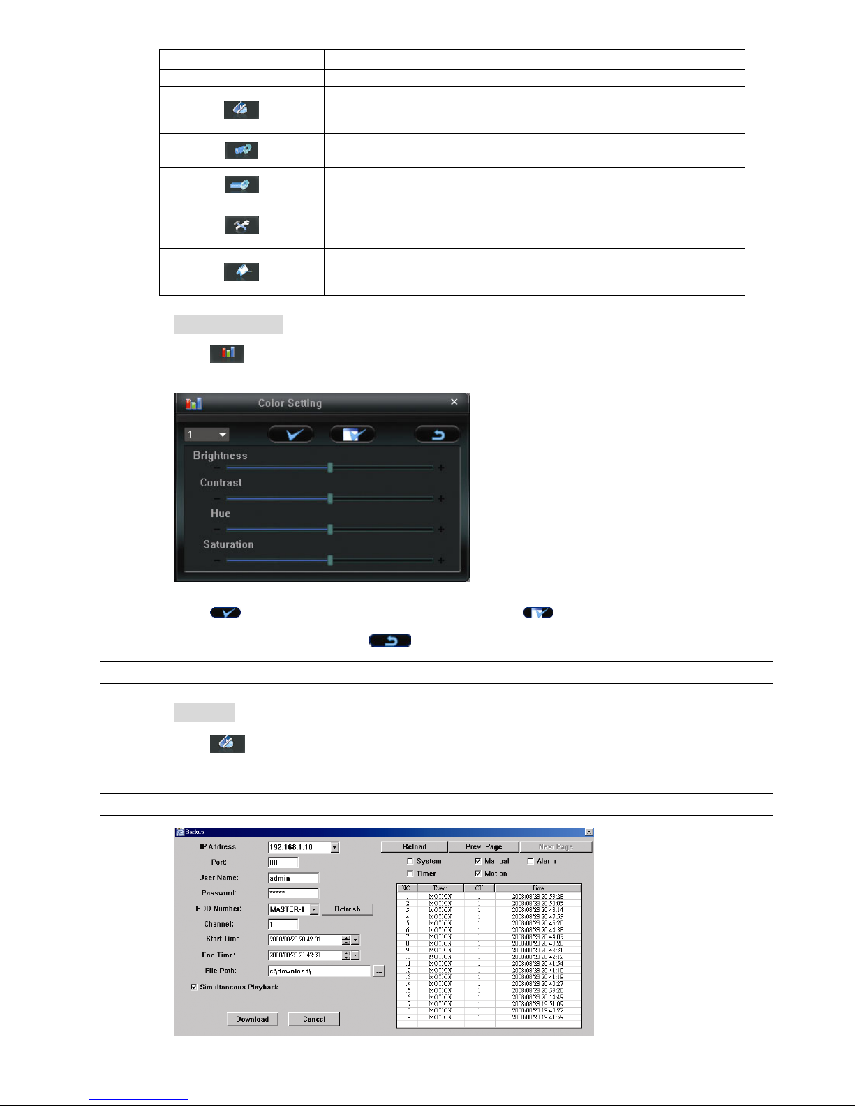
REMOTE OPERATION
~40~
Button Function Description
details, please see “Color Setting” at page 40.
Backup
To make a video backup remotely, click this button, and you
will go to the download setting page. For details, please see
“Network Backup” at page 37.
Record Setting
Click to go to the detailed record setting. Please refer to
“Record Setting” at page 41 for details.
Server Setting
Click to go into the detailed DVR setting. Please refer to
“Dvr Setting” at page 41 for details.
Tools
Click to update the firmware version, multilingual OSD and
boot display of your DVR remotely. Please refer to “Tools”
at page 51 for details.
Status List
Click to view all event and recording logs, search the desired
log(s) by date, or playback the recording of the selected log.
For details, please refer to Status List” at page 53.
CCoolloorr SSeettttiinngg
Click “ ” to go into the “Color Setting” page, and you can adjust the brightness / contrast / hue /
saturation for a single channel or all channels.
Choose the desired channel from the drop-down list, and click and drag the slider to make adjustment.
Click “ ” to apply the change to the selected channel, or “ ” to apply to all channels.
To restore to default values, click “ ”.
Note: You need to be a supervisor to operate this function. For details, please see “Account” at page 43.
BBaacckkuupp
Click “ ” (Backup) to go into the “Download” page, and you can select a specific time range or event
to make a video backup remotely.
Note: You need to be a supervisor to operate this function. For details, please see “Account” at page 43.
Page 45

REMOTE OPERATION
~41~
Function Description
IP Address / Port / User Name / Password Check if the network connection information of the DVR within which
contains the video data you need is correct.
HDD Number / Channel Specify the hard disk (HDD Number) and channel number (Channel)
within which have the video data you need.
Download by Time Specify the time range within which has the video data you want in the
“Start Time” and “End Time” columns.
Download by Event Select an event log from the event list. This list shows all logs in the
specified DVR from the latest to the earliest.
‧To quickly find the events you need, check or uncheck the event type
“System” / “Manual” / “Alarm” / “Motion”, and select the log you want.
‧To view the earlier or later logs that are not shown in the current page,
click “Prev. Page” or “Next Page”.
‧To refresh the event list, click “Reload”.
File Path Assign the location where the backup files are saved.
Simultaneous Playback To view the backup images simultaneously when the download process
is in progress, select Simultaneous Playback.
You will see the backup images while the images are being downloaded
to the PC or notebook.
To simply backup images without previewing, deselect Simultaneous
Playback. You will only see a message box indicating the total time
needed, the current status and the saving location.
Download / Cancel Click “Download” to start or “Cancel” to discard the video backup.
RReeccoorrdd SSeettttiinngg
Click “ ” to go into the “Record Setting” page and you can set the following items:
‧Record type
‧Hard disk overwriting
‧Pre- / post-alarm record time
‧Record time setting
‧Record path
Record type
In this section, you can select which type of the recording will be enabled. There are 4 options: Manual /
Schedule / Motion / Alarm.
Hard disk overwriting
To overwrite the recorded data from the earliest to the latest when the hard disk is full, check “Hard Disk
Overwrite” checkbox.
Pre- / post-alarm record time
Select the pre-/post-alarm recording time from 0 sec. to 10 sec.
Record time setting
There are two ways to set the record time: Weekly and Custom.
Page 46

REMOTE OPERATION
~42~
Weekly
Click “Weekly” tab, and you will see a weekly time table indicating the week days (Mon ~ Sun) and hours
(0 ~ 24), similar to the figure below:
X axis: 0 ~ 24 hours. Each time interval within a square is 15 minutes.
Y axis: Monday ~ Sunday.
Operation: You can set the record schedule for 3 record types as needed in this time table:
1st timeline – Schedule l recording, indicated in yellow,
2nd timeline -- Alarm recording, indicated in magenta, and
3rd timeline -- Motion recording, indicated in cyan.
Click and hold the start time point, and drag to the end time point to set the record time range.
Custom
Click “Custom” tab, and you can set a more specific record time range for the 3 record types: Schedule,
Motion, and Alarm.
How to add a new time setting:
1. Check the record type you want to schedule the recording.
2. Set the start time (From) and end time (To).
3. Click “Add” to add the time range you just set into the schedule table. Before adding the time range,
you will be prompted to confirm as follow:
Check if the information shown is correct. Click “OK” if the information is correct. Click “Cancel” if the
information is wrong.
How to modify / delete a current time setting:
1. Select the schedule setting you want to modify from the schedule table. The setting will be displayed in the left
setting panel.
2. Modify the setting in the left setting panel, and click “Update”.
Page 47

REMOTE OPERATION
~43~
3. You will be prompted to confirm the setting. Click “OK” if the information is correct. Click “Cancel” if the
information is wrong.
4. To delete one schedule setting, select it, and click “Delete”.
Record Path
Select and view the location for saving the recorded video and snapshot pictures.
To change the saving path for the recorded video clips or snapshots, check the drive you want, click the cell of
“Video Path” or “Picture Path” twice, and select a new path for saving the video clips or snapshots.
DDvvrr SSeettttiinngg
Click “ ” to view, set or modify the DVR setting. All the changes you make here will be applied to the
connected DVR.
Note: You need to be a supervisor to operate this function. For details, please see “Account” at page 43.
General
In “General” and its sub-menus, “Account” and “OnLineUser”, you can view and set some common settings,
such as the turbo step, make account setting, and check the information for all current on-line users.
In “General”, you will see the following items:
Item Description
Firmware Version Display the current firmware version of your DVR.
MAC Address Display the MAC address.
Turbo Step Speed up the menu selection from 1 to 30.
Ex: If the value of the turbo step is set to 5, one mouse-click will function as 5 mouse-clicks when you click
one of the buttons
/ / / in the DVR control panel.
Title Provide a title for this DVR. Only 16 characters are allowed.
Log
In “General” → “Log”, you can view the system event log(s) of the connected DVR for reference.
To check the previous / next page if there are more than one page, click “Prev. Page” / “Next Page”.
To refresh the event list, click “Reload”; to clear all log(s), click “Clean”.
Page 48

REMOTE OPERATION
~44~
Account
In “General” → “Account”, you can create a new account for login, or delete or modify the existing
account setting.
‧ To add an account, click “New”, and fill in the following columns. Then, click “Apply” to save your
setting and create a new account.
Column Description
User Name Set a user name that will be used for remote login. The user name allows up to 10 characters.
Password Set the password that will be used for remote login. The password allows up to 8 characters.
User Level Set the security level of an account to give the permission to control different AP functions. There are 4
user levels: Supervisor, Power User, Normal User and Guest.
For the functions each level is allowed to use, please see the information below:
Supervisor Power User Normal User Guest
Address Book
● ● ● ●
Miscellaneous Control
Color Setting
●
X X X
Backup
●
X X X
Record Setting
● ● ● ●
Dvr Setting
●
X X X
Tools
●
X X X
Log
● ● ● ●
Record
● ● ● ●
Snapshot
● ● ● ●
Information
● ● ● ●
Dvr Control
● ●
(except Menu
key)
●
(except Menu &
audio channel
keys)
X
Life Time Select how long this account is allowed to stay online (1 MIN / 5 MIN / 10 MIN / 1 HOUR / 1 DAY / INFINITE)
‧ To modify an existing account, select the account you want, change the setting, and click “Apply”.
‧ To remove an existing account, select the account you want, and click “Delete”.
Page 49

REMOTE OPERATION
~45~
‧ To save your changes, click “Apply”.
‧ To define the maximum account creation number, key in the number in “Max User(s)” column from 1
to 20, and click “Update”.
OnLineUser
In “General” → “OnLineUser”, you can check all the online user information. To update the user
information, click “Refresh”.
Network
In “Network” and its sub-menu, “DDNS”, “FTP” and “Mail”, you can set the DVR network configuration, and the
FTP or Email setting when an alarm is triggered. The network configuration allows the DVR to connect to the
LAN or Internet.
Select the network type you will be using for DVR connection. There are 3 network connection types: Static IP,
PPPOE and DHCP. For details about each connection type, please refer to “7.1.4 Network” at page 24.
Note: PPPOE and DHCP network connection types are required to apply the DDNS service to get a
“Hostname” to correspond to a dynamic IP address. Please refer to “DDNS” at page 45 for details.
DDNS
You need to apply a DDNS account before setting PPPOE or DHCP connection. DDNS is a service for
transforming the dynamic IP corresponding to a specific “host name”. Go to a website which provide free
DDNS services and apply a host name.
Page 50

REMOTE OPERATION
~46~
DDNS Apply:
a). Go to a website which provide the free DDNS service, for example, http://www.dyndns.org.
b). Create an account in DynDNS.
c). After creating one account, users will receive a confirmation E-mail within a few minutes. To complete
the registration, please follow the instructions received.
Users must complete these steps within 48 hours to complete the registration. If the confirmation
E-mail was not received within an hour, request “password reset”
(http://www.dyndns.org/account/resetpass/).
d). Use the DDNS username and password to log into the DynDNS.
e). Create a host name:
After login, click “Account” → “My Service” → “Add Host Services” → “Add Dynamic DNS Host”.
Enter and choose a host name, and click “Add Host”. Then, your DDNS host name is created.
FTP
If the FTP notification function is activated, the DVR will upload the captured images to the specified FTP
site once alarm-trigger or motion-trigger recording happened. Please enable the function of FTP
notification in the “Alarm” menu first.
FTP Notification Function:
a. Enter the detailed FTP information.
b. After finishing the setting, click “APPLY” to confirm.
MAIL
If the e-mail notification function is activated, the DVR will send an e-mail notification to the specified
recipients once alarm-trigger or motion-trigger recording happened. Please enable the function of e-mail
notification in the “Alarm” menu first.
Page 51

REMOTE OPERATION
~47~
Mail Notification Function:
a. Add the recipients’ E-mail accounts in “Mail Account” column.
Please type the entire E-mail address in the “Mail from” column to ensure E-mails will not be blocked by
SMTP.
For detailed information (SMTP server, username and password), please check with your E-mail service
supplier.
b. Some mail servers are required to verify the password. Please enter the “user name” and “password”.
c. After finishing the setting, click “APPLY” to confirm.
Note: Mail addresses can be added up to 4.
Video
In “Video”, you can set the video web transmission size and quality, and the frame rate for transmitting.
Function Description
JPEG Choose the image size (4CIF / CIF) and picture quality (BEST / HIGH / NORMAL / BASIC) when
the web transmission format is JPEG.
MPEG Choose the image size (4CIF / CIF) and picture quality (BEST / HIGH / NORMAL / BASIC) when
the web transmission format is MPEG.
FrameRate Choose the frame rate for transmitting (FULL / HALF / ONE THIRD / ONE QUARTER / ONE
FIFTH / ONE TENTH).
Dvr
In “Dvr” and its sub-menus, “Camera”, “Device”, “Detection”, “Record”, “Record Timer”, “Alert” and “Display,”
you can set DVR general functions, such as the host ID, the record schedule, alerts, motion detection, and text
or icon display, etc.
Page 52

REMOTE OPERATION
~48~
In “Dvr”, you can see the following items:
Function Description
Host ID Set the host ID from 0 to 254. The default value is 0.
System Type Display the current system type (NTSC / PAL). It’s automatically detected.
DeInterlace Choose to reduce (ON) or ignore (OFF) the vibration of the paused picture.
Daylight Saving
Specify whether to use daylight saving time (ON / OFF).
If this function is enabled, set the time period (START / END), and adjust the daylight saving time in hours
(ADJUST).
Menu Operation
Select the time-out in seconds after which the DVR keys will be automatically locked when no one is
operating the DVR for a period of time (0 / 30 / 60 / 120). The default value is 30.
Serial Type
Display the serial type (RS485) used by this DVR. It’s automatically detected.
BaudRate
Choose a baud rate used by this DVR from the drop-down list (2400 / 9600 / 19200 / 38400 / 57600 /
115200). The default value is 2400.
Camera
In “Dvr” → “Camera”, you can specify a channel to enable the recording function by selecting the check
box “Record”, choose to activate the “Covert Recording” function by selecting the check box “Cover”, and
rename the channel title which will be displayed in the live view screen by double-clicking the channel
title.
Device
Select the device type (CAMERA / PTZ) according to the connected cameras for each channel. Click
“Edit” or double click the item to enter the setting box.
Page 53

REMOTE OPERATION
~49~
Function Description
Device Type Choose either normal camera or PTZ camera.
ID No. Set the ID number (0 ~ 255) of the connected PTZ camera.
Protocol Type Choose “NORMAL” or “P-D” protocol. It is recommended to select PELCO-D protocol for the
connected PTZ camera of other brands. Please choose Normal if it’s our own PTZ camera
Baud Rate Set the baud rate of each channel (2400 / 4800 / 9600 / 19200 / 38400 / 57600 / 115200).
Detection
Select the desired channel, and click “Edit” to enter the motion detection sensitivity and area-setting page.
Please see the description below for each function:
Function Description
DETECT Enable (ON) or disable (OFF) the function of “Motion Detection”.
If this function is enabled, you might need to set the motion detection sensitivity or simply keep the
default values. For details, please see the description below.
Motion Detection
Sensitivity
(LS / SS / TS / RE)
Set the detection sensitivity in 4 different adjustable parameters (LS / SS / TS / RE). For details
about each parameter, please refer to “7.1.2 Detection” at page 21.
Alarm Select N.C. (normal closed) / N.O. (normal opened) / OFF for the alarm polarity. For N.C. / N.O.
contact details, please refer to “APPENDIX 2”.
Motion Detection
Setting Area
Set the motion detection area by selecting the area grids with your mouse. Pink grids represent
the area that is not being detected while the transparent grids are the area under detection. You
can set multiple areas under detection.
Click “-” (Clear All) to set the whole area undetected.
Click “+” (Select All) to set the whole area under detection.
Apply / Return To save the setting, click “Apply” and return to “Dvr Setting” window.
To discard the setting, click “Return” to directly return to “Dvr Setting” window without saving.
Record
In “Dvr” → “Record”, you will see the following items for DVR record settings.
Page 54

REMOTE OPERATION
~50~
Function Description
Image Size / Quality Choose the image size (FRAME / FIELD / CIF) and quality (BEST / HIGH / NORMAL / BASIC).
Manual Record / Event
Record / Timer Record
Select the record type that the DVR will take recording (Yes / No), and select the IPS setting for the
selected record type.
Pre-Alarm Record Check this option if you want to enable the pre-alarm recording function.
When any alarm is triggered, the DVR will record 8MB video data before the alarm event is actually
happened.
Overwrite Select “Yes” to enable the HDD overwrite function when the HDD is full, or “No” to disable this
function.
When this function is on, and the recording and the pre-alarm function are activated, the DVR will
overwrite 8GB data from the oldest for continuous recording without notice.
Record Timer
In this menu list, you can set the record schedule for normal recording or motion recording.
‧ Permit
Select this checkbox to allow the record timer setting to be applied to the connected DVR. If this
checkbox is deselected, the setting will not be applied to the connected DVR even when you click
“Apply” and “OK”.
‧ Routine / Motion
Click “Routine” tab to select the time range for continuous recording, or “Motion” tab to select the time
range within which the recording will be on when any movement is detected.
‧ Time Table
Find the day and time you want to enable the recording. Then, click to select the time interval(s). Each
interval represents 30 minutes.
To enable the recording all the time, click “+”; to clear the record timer setting, click “-”.
Alert
In “Alert”, you can set the DVR to beep for notification when there’s any alert happened. Check the
buzzer option you want, and set how long the beep sound will be lasted.
Page 55

REMOTE OPERATION
~51~
Function Description
Ext Alert Check this option to enable the external alert.
Buzzer Enabled This option must be checked for “Motion Buzzer”, “Alarm Buzzer”, “Video Loss
Buzzer”, and “Key Input Buzzer” to take effects.
Motion Buzzer / Alarm Buzzer /
Video Loss Buzzer / Key Input
buzzer
Check one of these 4 options, and you will hear the beep sound when any movement
is detected / the alarm is triggered / video loss occurs / any DVR key is pressed.
Notified by Select the notification method when any event occurs: Email or FTP.
Duration Set the alert and buzzers to beep for 5 / 10 / 20 / 40 seconds.
Display
In “Display”, you can choose whether to display some text indication or icons, set the channel display
switch time-out, set the DVR time remotely, and select the date format (Y-M-D / M-D-Y / D-M-Y).
Function Description
Title Select to display the channel title in the live view.
Event Select to display the event symbol in the live view.
Quick Status Select to display the quick status in the live view.
Full Sequence Duration /
Quad Sequence Duration
Set the time-out in seconds (3 / 5 / 10 / 15) after which the channel display will be switched
by one channel (Full Sequence Duration) or by four channels (Quad Sequence Duration).
Note: “Quad Sequence Duration” is disabled for the 4CH DVR model.
Server Time Set the DVR time remotely.
Date Format Choose the date display format appropriate to your location (Y-M-D, M-D-Y and D-M-Y).
TToooollss
Click “ ” to upgrade your DVR (Update Server), or select the language of the video viewer (Language).
Note: You need to be a supervisor to operate this function. For details, please see “Account” at page 43.
Note: Do not disconnect the power of your DVR while the upgrade process is in progress, or the DVR
functions may not work properly or be unable to use.
Page 56
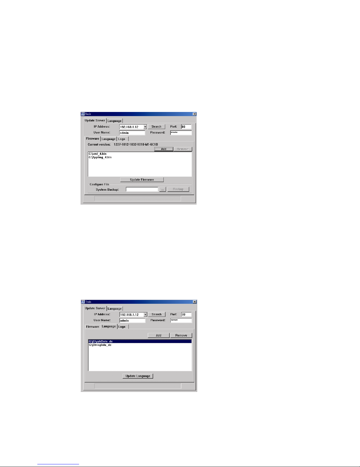
REMOTE OPERATION
~52~
Update Server
3 update options are available for this function: Firmware, Language and Logo.
Before performing any update, finish the following settings first:
1) Choose the IP address of the DVR whose firmware needs to be updated from the drop-down list, or
click “Search” to find.
2) Key in the user name, password and port number used to access your DVR remotely.
3) Select the update option (Firmware / Language / Logo) you want. For details, please see the
description below.
‧Firmware
To upgrade your DVR firmware remotely, click “Firmware” tab, and follow the steps below:
a). In the “Firmware” section, you will see the current firmware version. To upgrade the firmware
version of your DVR, click “Add” to locate and select the firmware file. The file will be shown in the
firmware list.
b). If you want to backup your system before upgrading the firmware version of your DVR, select
“System Backup” in the “Configure File” section, click “…” to specify the location for saving system
backup, and click “Backup” to start the backup process.
c). To start upgrading the DVR firmware, choose the file from the firmware list, and click “Update
Firmware” to start the upgrade process.
‧Language
To update the DVR OSD language, click “Language” tab, and follow the steps below:
a). Get the language files you want to update from your distributor.
b) Click “Add” to locate and select the files needed. The files will be shown in the list. If you add the
wrong file, select it and click “Remove”.
c). To start updating the OSD language, choose the files from the list, and click “Update Language” to
start the upgrade process.
Page 57

REMOTE OPERATION
~53~
‧Logo
To replace the logo shown in the DVR boot display, click “Logo” tab, and follow the steps below:
a). Prepare a graphic file in the “BMP” format for replacement.
Note: Use the image software to set the image size to 320 * 240, and save the image as an 8-bit
(64-color) image in the "BMP" format.
b) Click “Add” to locate and select the graphic file. The file will be shown in the list. If you add the wrong
file, select it and click “Remove”.
c). To start updating the logo, choose the file from the list, and click “Update Logo” to start the upgrade
process.
Language
This software is available in English / Chinese / French / German / Portuguese / Spanish / Japanese.
Select a language from the drop-down list, and click “Apply”. You will be prompted to restart the
application for this change to take effect.
SSttaattuuss LLiisstt
Click “ ” to view all the event and record logs (All), or search for the specific log(s) by date or by record
type (Condition).
There are three types of logs: Event, Record and Backup. To playback the recorded data for a specific record
or backup log, select the log, and double-click to start the video playback.
For detailed playback operation, please refer to “Playback” at page 54.
Page 58

REMOTE OPERATION
~54~
Function Description
Time Range To find the specific logs, set the time range (From / To), and the range unit here.
Record Type Select the record type you want to search (User / Alarm / Motion / RETR).
Query Click to start sorting the logs specified.
Delete / Delete All Click “Delete” to remove the selected log(s), or click “Delete All” to clear the current log list.
Tip: To select more logs all at once, press and hold the “Ctrl” key on your keyboard, and
click to select the logs you want to remove.
Play Click to play the selected record log. The playback panel will be shown for your further
operation. For playback details, please refer to Playback Screen” at page 54.
Repair Click to fix the log with errors.
Close Click “Close” to quit this window.
Playback Screen
When you select and play the recorded data for a specific log in “ ” “Record” or “Backup”, you will
immediately go into the playback mode, and the following playback panel appears. For the function of
each part on the panel, please refer to the following description.
NO. Function Description
1
Playback / Download
Info Display
This area shows the detailed playback / download information, such as the file name,
record date and time, and the speed, etc.
2
Playback Progress Bar This area shows the playback progress and the progress percentage.
3
De-Interlace Click to reduce the vibration of the paused picture.
4 Playback Operation This area is enabled only when the playback is started.
(Rewind) / (Forward) / (Stop) / (Pause) / (Play)
Rewind / Forward
Click once to get 2X fast rewind / forward, twice to get 4X, three times to get 8X, and
four times to get 16X the highest.
Page 59

REMOTE OPERATION
~55~
Information
To view the current network connection details, click this button.
DVR Control
When Video Viewer is connected to the DVR, this DVR control panel will be enabled, and you can control
the DVR remotely. For the function of each button, please refer to the following description.
Note: The control panel below is taking 16CH DVR model as an example. Some buttons may not be
enabled for 8CH or 4CH DVR models.
Function Description
Click the channel No. (depending on the DVR model you have) to see the live view of the selected channel.
Click the view mode you want to see. There are 10 modes for your choice:
View CH1, CH2, CH5 and CH6
View CH3, CH4, CH7 and CH8
View CH9, CH10, CH13 and CH14
View CH11, CH12, CH15 and CH16
View the 1
st
channel of the selected 4-cut view mode
View the 2
nd
channel of the selected 4-cut view mode
View the 3
rd
channel of the selected 4-cut view mode
View the 4
th
channel of the selected 4-cut view mode
Channel Selection
Click to switch the 4-cut channel display. This button is available only for selected models.
Page 60

REMOTE OPERATION
~56~
Function Description
Click to see the 9-cut channel display.
Click to see the whole 16 channels.
You can also click “
” or “ ” to go to the previous / next channel of the selected channel.
Digital Zoom
Click
to zoom in / out the selected channel image.
Full Sequence /
Quad Sequence
Quad Sequence
Click to display the 4 quad display modes one by one.
The 1
st
view is CH1, CH2, CH5 & CH6,
the 2
nd
view is CH3, CH4, CH7 & CH8,
the 3
rd
view is CH9, CH10, CH13 & CH14, and
the 4
th
view is CH11, CH12, CH15 & CH16.
When the 4
th
view is displayed, it will start from the 1st view again.
To exit from this display mode, click any other channel display button.
Full Sequence
Click to display each channel one by one, starting from CH1. When the last channel is displayed, it will start from
CH1 again.
To exit from this display mode, click any other channel display button.
Search
Click “
” to enter the DVR full search menu.
You can check all the logs here, and select one of them to payback.
Playback (Stop) / (Pause) / (Rewind) / (Play) / (Slow Playback) / (Forward)
Rewind / Forward
Click once to get 4X fast rewind / forward, twice to get 8X, three times to get 16X, and four times to get 32X the
highest.
Slow Playback
Click once to get 4X slow playback and twice to get 8X slow playback.
Menu and Arrow Keys
Click “
” (Menu) to enter the menu / exit the menu mode.
Click the arrow keys to move the cursor and make the selection:
/ : Move up / down to select the previous / next menu or sub-menu function, or change the setting.
/ : Move left / right to the previous / next sub-menu items.
Enter
Click “
” to confirm the setting or enter your selection.
Event Click to get access to the time & event search mode.
Page 61

REMOTE OPERATION
~57~
8.2 IE Web Browser
You can view the images or operate your DVR with IE web browser.
Note: The supported PC operation systems are Windows 2000 and Windows XP.
Step 1: Key in the IP address used by your DVR in the URL address box, such as 60.121.46.236, and press Enter.
You will be prompted to enter the user name and password to access the DVR.
If the port number your DVR used is NOT 80, you need to key in the port number additionally. The format is
ipaddress:portnum. For example, for IP address 60.121.46.236 and port No. 888, please key
in ”http://60.121.46.236:888” into the URL address box, and press “Enter”.
Step 2: Enter the user name and password, the same as the ones used at AP login, and press “OK”. You will see a
similar screen as the following when the login information is correct.
NO. Function Description
1 Home
Click
to go to the main page of the DVR
2
Config.
Click
to go to the detailed DVR setting.
3
Menu and Arrow
Keys
Click
to enter the menu / exit the menu mode.
Click the arrow keys to move the cursor and make the selection:
/ : Move the cursor up / down to select the previous / next menu or sub-menu function, or change the setting.
/ : Move the cursor left / right to the previous / next sub-menu items.
4 Key Lock
Click
to enable the DVR key lock function. To unlock the DVR, key in your password, and click .
Page 62

REMOTE OPERATION
~58~
NO. Function Description
5 Enter
Click
to confirm the setting or enter your selection.
6 Digital Zoom
Click
to zoom in / out the selected channel image.
7 Search
Click
to enter the DVR full search menu.
You can check all the logs here, and select one of them to payback.
8
Playback control
buttons
(Stop) / (Play) / (Rewind) / (Forward) / (Pause) / (Slow Playback)
Rewind / Forward
Click once to get 4X fast rewind / forward, twice to get 8X, three times to get 16X, and four times to get 32X the
highest.
Slow Playback
Click once to get 4X slow playback and twice to get 8X slow playback.
9
Single Channel
Selection
Click the channel No. (CH1 ~ CH16) to see the live view of the selected channel.
You can also click
or to go to the previous / next channel of the selected channel.
10 Display Mode
Click the display mode you want to see. There are 3 modes for your choice:
Click
/ / to show 4-cut / 9-cut / 16-cut display.
11 Snapshot
Click
to take a snapshot for the current view, and open another browser window to display the captured
image.
12
Quad Sequence /
Full Sequence
Quad Sequence
Click to display the 4 quad display modes one by one.
The 1
st
view is CH1, CH2, CH5 & CH6,
the 2
nd
view is CH3, CH4, CH7 & CH8,
the 3
rd
view is CH9, CH10, CH13 & CH14, and
the 4
th
view is CH11, CH12, CH15 & CH16.
When the 4
th
view is displayed, it will start from the 1st view again.
To exit from this display mode, click any other channel display button.
Full Sequence
Click to display each channel one by one, starting from CH1. When CH16 is displayed, it will start from CH1
again.
To exit from this display mode, click any other channel display button.
13
Web
Transmission
MPEG4 / JPEG / QuickTime
QuickTime is Apple Inc.’s multimedia software. You need to have QuickTime installed in you operation system
first. When “QuickTime” is selected, you will be promoted to enter the user name and password to access the
server of the DVR.
14 Change Quality
BEST / HIGH / NORMAL / BASIC
Click to change the image quality.
15
Change
Resolution
4 CIF / CIF
Click to change the image resolution (4CIF: 720*480 / CIF: 352*240)
16
Audio Channel
Selection
To hear the audio for a channel that supports audio recording in the live mode, click 1, 2, 3 or 4 to hear the audio
from the audio channel 1, 2, 3 or 4.
This function is not available for 4CH DVR model without a fan.
For the audio channel(s) of each model, please see “11).
/ ” in “2.1 Front Panel” at page 4.
means the audio channel is not connected to the camera supporting audio.
Page 63

REMOTE OPERATION
~59~
8.3 QuickTime Player
You can also use the QuickTime player to remotely log into the DVR and check the live view only.
Note: QuickTime is Apple’s multimedia software. You need to have QuickTime installed in you operation system
first, and you can access the DVR to see the live view.
If you have installed QuickTime, please skip Step 1.
Step 1: Go to Apple’s official website to download QuickTime. The website address is as follows:
http://www.apple.com/quicktime/win.html
a). Click “DDoowwnnllooaadd” to go into the download page, and select to download the free player.
b). Leave your Email address, and click “FFrreeee DDoowwnnllooaadd NNooww” to download the latest QuickTime player.
c). When the download is completed, execute the “QQuuiicckkTTiimmeeIInnssttaalllleerr..eexxee” file, and follow the on-screen
instructions to finish the installation procedure.
Step 2: Open your QuickTime player. Select “File” → “Open URL”, and key in the URL address.
The URL format is “rtsp://ipaddress/live/mpeg4” (For example, “rtsp://59.124.231.75/live/mpeg4”).
Click “OK” to continue.
Step 3: A pop-up window will appear and prompt you to enter the authentication information. Key in the user
name and password for accessing your DVR. The user name and password are the same as the ones
you use to log into Video Viewer.
If the information is correct, click “OK” to go on. If not, click “Cancel” to quit the accessing.
Step 4: When the login is successful, you will see a similar screen as the following.
Page 64

APPENDIX 1 PIN CONFIGURATION
~60~
APPENDIX 1 PIN CONFIGURATION
‧ For 16CH DVR
Siren: When the DVR is triggered by alarm or motion, the COM
connects with NO and the siren with strobe starts wailing and
flashing.
Magnetic Contact: When the magnetic contact is opened, the
alarm will be triggered and the recording is on.
PIN FUNCTION DESCRIPTION
1 GND GROUND
2~9 ALARM INPUT
Connect ALARM INPUT (PIN 2 -- 9) and GND (PIN 1) connector with wires. Once an
alarm is triggered, the DVR will start recording and the buzzer will be on.
PIN 2 is Alarm 1. Once the alarm is triggered, the CH1 of the DVR will start alarm-triggered recording.
PIN 3 is Alarm 3. Once the alarm is triggered, the CH3 of the DVR will start alarm-triggered recording.
PIN 4 is Alarm 5. Once the alarm is triggered, the CH5 of the DVR will start alarm-triggered recording.
PIN 5 is Alarm 7. Once the alarm is triggered, the CH7 of the DVR will start alarm-triggered recording.
PIN 6 is Alarm 9. Once the alarm is triggered, the CH9 of the DVR will start alarm-triggered recording.
PIN 7 is Alarm 11. Once the alarm is triggered, the CH11 of the DVR will start alarm-triggered recording.
PIN 8 is Alarm 13. Once the alarm is triggered, the CH13 of the DVR will start alarm-triggered recording.
PIN 9 is Alarm 15. Once the alarm is triggered, the CH15 of the DVR will start alarm-triggered recording.
10 PIN OFF NA
11 PIN OFF NA
12 RS485-A
Using RS-485 serial communication signals, DVR can be controlled by keyboard
controller, or controls PTZ cameras.
13 EXTERNAL ALARM NO
Under the normal operation, COM disconnects with NO. But when any alarm is
triggered, COM connects with NO.
Attention: The voltage restriction is under DC24V 1A.
14 PIN OFF NA
15~22 ALARM INPUT
Connect ALARM INPUT (PIN 15 – 22) and GND (PIN 1) connector with wires. Once
an alarm is triggered, the DVR will start recording and the buzzer will be on.
PIN 15 is Alarm 2. Once the alarm is triggered, the CH2 of the DVR will start alarm-triggered recording.
PIN 16 is Alarm 4. Once the alarm is triggered, the CH4 of the DVR will start alarm-triggered recording.
PIN 17 is Alarm 6. Once the alarm is triggered, the CH6 of the DVR will start alarm-triggered recording.
PIN 18 is Alarm 8. Once the alarm is triggered, the CH8 of the DVR will start alarm-triggered recording.
PIN 19 is Alarm 10. Once the alarm is triggered, the CH10 of the DVR will start alarm-triggered recording.
PIN 20 is Alarm 12. Once the alarm is triggered, the CH12 of the DVR will start alarm-triggered recording.
PIN 21 is Alarm 14. Once the alarm is triggered, the CH14 of the DVR will start alarm-triggered recording.
PIN 22 is Alarm 16. Once the alarm is triggered, the CH16 of the DVR will start alarm-triggered recording.
23 PIN OFF NA
24 RS485-B
Using RS-485 serial communication signals, DVR can be controlled by keyboard
controller, or controls PTZ cameras.
25 EXTERNAL ALARM COM
Under the normal operation, COM disconnects with NO. But when any alarm is
triggered, COM connects with NO.
Attention: The voltage restriction is under DC24V 1A.
Page 65

APPENDIX 1 PIN CONFIGURATION
~61~
‧ For 8CH DVR
Siren: When the DVR is triggered by alarm or motion, the COM
connects with NO and the siren with strobe starts wailing and
flashing.
Magnetic Contact: When the magnetic contact is opened, the
alarm will be triggered and the recording is on.
PIN FUNCTION DESCRIPTION
1
GND GROUND
2~5
ALARM INPUT
Connect ALARM INPUT (PIN 2 – 5) and GND (PIN 1) connector with wires. Once an
alarm is triggered, the DVR will start recording and the buzzer will be on.
PIN 2 is Alarm 1. Once the alarm is triggered, the CH1 of the DVR will start alarm-triggered recording.
PIN 3 is Alarm 3. Once the alarm is triggered, the CH3 of the DVR will start alarm-triggered recording.
PIN 4 is Alarm 5. Once the alarm is triggered, the CH5 of the DVR will start alarm-triggered recording.
PIN 5 is Alarm 7. Once the alarm is triggered, the CH7 of the DVR will start alarm-triggered recording.
6 ~ 11
PIN OFF NA
12
RS485-A
Using RS-485 serial communication signals, DVR can be controlled by keyboard
controller, or controls PTZ cameras.
13
EXTERNAL ALARM NO.
Under the normal operation, COM disconnects with NO. But when any alarm is
triggered, COM connects with NO.
Attention: The voltage restriction is under DC24V 1A.
14
PIN OFF NA
15~18
ALARM INPUT
Connect ALARM INPUT (PIN 15 – 18) and GND (PIN 1) connector with wires. Once
an alarm is triggered, the DVR will start recording and the buzzer will be on.
PIN 15 is Alarm 2. Once the alarm is triggered, the CH2 of the DVR will start alarm-triggered recording.
PIN 16 is Alarm 4. Once the alarm is triggered, the CH4 of the DVR will start alarm-triggered recording.
PIN 17 is Alarm 6. Once the alarm is triggered, the CH6 of the DVR will start alarm-triggered recording.
PIN 18 is Alarm 8. Once the alarm is triggered, the CH8 of the DVR will start alarm-triggered recording.
19~23
PIN OFF NA
24
RS485-B
Using RS-485 serial communication signals, DVR can be controlled by keyboard
controller, or controls PTZ cameras.
25
EXTERNAL ALARM COM
Under the normal operation, COM disconnects with NO. But when any alarm is
triggered, COM connects with NO.
Attention: The voltage restriction is under DC24V 1A.
Page 66

APPENDIX 1 PIN CONFIGURATION
~62~
‧ For 4CH DVR
Siren: When the DVR is triggered by alarm or motion, the COM
connects with NO and the siren with strobe starts wailing and
flashing.
Magnetic Contact: When the magnetic contact is opened, the
alarm will be triggered and the recording is on.
PIN FUNCTION DESCRIPTION
1~2
PIN OFF NA
3~6
ALARM INPUT
Connect ALARM INPUT (PIN 3 – 6) and GND (PIN 9) connector with wires. Once an
alarm is triggered, the DVR will start recording and the buzzer will be on.
PIN 3 is Alarm 1. Once the alarm is triggered, the CH1 of the DVR will start alarm-triggered recording.
PIN 4 is Alarm 2. Once the alarm is triggered, the CH2 of the DVR will start alarm-triggered recording.
PIN 5 is Alarm 3. Once the alarm is triggered, the CH3 of the DVR will start alarm-triggered recording.
PIN 6 is Alarm 4. Once the alarm is triggered, the CH4 of the DVR will start alarm-triggered recording.
7
NC
Under the normal operation, COM connects with NC and disconnects from NO.
But when any alarm is triggered, COM disconnects with NC and connects with
NO.
Attention: The voltage restriction is under DC24V 1A.
8
NO
Under the normal operation, COM disconnects with NO. But when any alarm is
triggered, COM connects with NO.
Attention: The voltage restriction is under DC24V 1A.
9
GND GROUND
10
RS485-B
Using RS-485 serial communication signals, DVR can be controlled by keyboard
controller.
11
RS485-A
Using RS-485 serial communication signals, DVR can be controlled by keyboard
controller.
12~14
PIN OFF NA
15
EXTERNAL ALARM COM
Under the normal operation, COM disconnects with NO. But when any alarm is
triggered, COM connects with NO.
Attention: The voltage restriction is under DC24V 1A.
Page 67

APPENDIX 2 COMPATIBLE USB FLASH DRIVE BRAND
~63~
APPENDIX 2 COMPATIBLE USB FLASH DRIVE BRAND
Please upgrade the firmware of the DVR to the latest version to ensure the accuracy of the following table. If the
USB flash drive is not supported by the DVR, the "USB ERROR" message will be shown on the screen.
Note: Please use your PC to format the USB flash drive as "FAT32".
MANUFACTURER MODEL CAPACITY
256MB
JetFlash 110
512MB
JetFlash V30
1GB
JetFlash 150
1GB
JetFlash V20
1GB
Transcend
JFV10
4GB
256MB
512MB
Kingston
DataTraveler DTI KUSBDTI/256FE
2GB
256MB
PQI
Cool Drive (U339)
512MB
256MB
HANDY STENO HF202
512MB
USB2.0 Flash Drive HS120
1GB
USB2.0 Flash Drive AH320
1GB
Apacer
AH221
2GB
USB2.0 Flash Disk-PD1
1GB
USB2.0 Flash Disk-RB15
1GB
USB2.0 Flash Disk-PD4
1GB
Adata
PD10
2GB
128MB
256MB
512MB
1GB
Sandisk
Cruzer Micro
4GB
Page 68

APPENDIX 3 COMPATIBLE HDD BRAND
~64~
APPENDIX 3 COMPATIBLE HDD BRAND
Please upgrade the firmware of the DVR to the latest version to ensure the accuracy of the following table.
‧ For IDE HDD
MANUFACTURER MODEL CAPACITY ROTATION
Deskstar 7K250, HDS722516VLAT20 160GB 7200 rpm
HDS722516VLAT80 160GB 7200 rpm
HDS722516DLAT80 160GB 7200 rpm
Deskstar 7K250, HDS722525VLAT80 250GB 7200 rpm
HITACHI
Deskstar 511DHT0021 500GB 7200 rpm
DiamondMax Plus 9, Model#6Y160L0 160GB 7200 rpm
DiamondMax 10 6L160R0 160GB 7200 rpm
DiamondMax 10 6L200R0 200GB 7200 rpm
DiamondMax 10 6L200PO 200GB 7200 rpm
MaxLine Plus Ⅱ, Model#7Y250P0
250GB 7200 rpm
DiamondMax 10 6L250R0-3 250GB 7200 rpm
Maxtor
DiamondMax 10 HDMA6L300RO-3 300GB 7200 rpm
Barracuda 7200.7 Plus, ST3160023A 160GB 7200 rpm
Barracuda 7200.8 ST3200826A 200GB 7200 rpm
Barracuda 7200.8 ST3250826A 250GB 7200 rpm
Barracuda 7200.8 ST3300831A/P 300GB 7200 rpm
Barracuda 7200.8 ST3400832A/P 400GB 7200 rpm
7200.9 ST3200827A/P 200GB 7200 rpm
7200.10 ST3250620A/P 250GB 7200 rpm
Seagate
7200.10 ST3320620A/P 320GB 7200 rpm
Caviar SE WD1600JB 160GB 7200 rpm
Caviar WD2000BB-00DWA0 200GB 7200 rpm
Caviar SE WD2500JB 250GB 7200 rpm
Western Digital
Cavir RE WD2500SB-01KBC0 250GB 7200 rpm
Page 69

APPENDIX 3 COMPATIBLE HDD BRAND
~65~
‧ For SATA HDD
MANUFACTURER MODEL CAPACITY ROTATION
HDS721680PLA380 80GB 7200 rpm
HDT725032VLA360 320GB 7200 rpm
HITACHI
HDS721010KLA330 1000GB 7200 rpm
STM3500320AS 500GB 7200 rpm
Maxtor
STM3750330AS 750GB 7200 rpm
ST31000340AS 1000GB 7200 rpm
Seagate
ST31000340SV 1000GB 7200 rpm
WD5000AACS 500GB 7200 rpm
WD5000KS 500GB 7200 rpm
WD7500AAKS 750GB 7200 rpm
Western Digital
WD10EACS 1000GB 7200 rpm
Page 70

APPENDIX 4 RECORDING TIME TABLE
~66~
APPENDIX 4 RECORDING TIME TABLE
The testing environment for this recording time table is office, for reference only
Recording time varies depending on the following three factors:
‧ Different camera resolution;
‧ Different picture complexity;
‧ Different frequency of the object movement
Note: This recording time table applies to 4CH / 8CH / 16CH DVR.
Record mode Quality IPS GB/hour 750GB record time(hour) 750GB record time(day)
25 1.77 423.729 17.7
12 1.23 609.756 25.4
7 0.68 1102.941 46.0
Best
3 0.48 1562.500 65.1
25 1.32 568.182 23.7
12 0.83 903.614 37.7
7 0.54 1388.889 57.9
High
3 0.43 1744.186 72.7
25 1.1 681.818 28.4
12 0.7 1071.429 44.6
7 0.45 1666.667 69.4
Normal
3 0.35 2142.857 89.3
25 0.912 822.368 34.3
12 0.57 1315.789 54.8
7 0.4 1875.000 78.1
Frame
Basic
3 0.3 2500.000 104.2
50 1.74 431.034 18.0
25 1 750.000 31.3
12 0.672 1116.071 46.5
Best
7 0.468 1602.564 66.8
50 1.39 539.568 22.5
25 0.852 880.282 36.7
12 0.552 1358.696 56.6
High
7 0.408 1838.235 76.6
50 1.333 562.641 23.4
25 0.744 1008.065 42.0
12 0.516 1453.488 60.6
Normal
7 0.372 2016.129 84.0
50 1.025 731.707 30.5
25 0.648 1157.407 48.2
12 0.41 1829.268 76.2
Field
Basic
7 0.3 2500.000 104.2
100 2.4 312.500 13.0
50 1.4 535.714 22.3
25 0.78 961.538 40.1
Best
12 0.53 1415.094 59.0
100 1.84 407.609 17.0
50 1.34 559.701 23.3
CIF
High
25 0.65 1153.846 48.1
Page 71

APPENDIX 4 RECORDING TIME TABLE
~67~
Record mode Quality IPS GB/hour 750GB record time(hour) 750GB record time(day)
12 0.42 1785.714 74.4
100 1.584 473.485 19.7
50 0.9 833.333 34.7
25 0.545 1376.147 57.3
Normal
12 0.36 2083.333 86.8
100 1.21 619.835 25.8
50 0.7 1071.429 44.6
25 0.43 1744.186 72.7
Basic
12 0.3 2500.000 104.2
Page 72

APPENDIX 5 TROUBLESHOOTING
~68~
APPENDIX 5 TROUBLESHOOTING
Please refer to the table below for easy troubleshooting. The table describes some typical problems and also their
solutions. Please check them before calling your DVR dealer.
‧ FAQ (Frequently ask question)
Questions Solutions
Check power cord connection. No power
Confirm that there is power supplied from the outlet.
DVR is not working when pressing any button You might be under “Key Lock” mode. Press any key and enter the password to exit
this mode.
Replace with another HDD for testing.
Replace with another HDD cable for testing.
HDD detection failed
Make sure HDD “Master”, “Slave” mode is correctly set.
Replace with another USB flash drive for testing. Can’t detect your USB flash drive
Format the USB flash drive as FAT32 format and try again.
Confirm the camera is power supplied.
Check the setting of the camera lens.
Check the monitor’s video cable and connection.
No live images
Check the camera’s video cable and connection.
B/W or flashing live images Make sure the DVR video system conforms with your local system as follows:
4. Turn off the DVR.
5. Connect your camera(s) to the DVR and power supply, and turn on the DVR
again. The DVR will automatically detect the video system (NTSC/ PAL) in
your region.
Check if the HDD is installed and connected properly. No recorded video
Check the “MANUAL RECORD ENABLE” is set to “ON” , and the record function in
the “CAMERA” menu is set to “ON” too.
Timer recording is not working Check if “TIMER RECORD ENABLE” option is set to “ON” and the timer schedule
has been arranged.
Check if “EVENT RECORD ENABLE” option is set to “ON”.
Check the detection function “DET” is set to “ON”.
Motion detection recording is not working
Check the detection area “AREA” has been setup.
Can’t play the recorded data on my DVR There must be at least 8192 images of recorded data for playback to work properly.
If not, your DVR will stop the playback.
For example, if the IPS is set to 30, the recording time should be at least 273
seconds (8192 images / 30 IPS) for the playback to work properly.
Can’t backup the video with audio Make sure the audio cameras are connected to the DVR channels which support
the audio function (CH1, CH2, CH3 and CH4).
Check the DVR firmware version. Can’t view the DVR images over the network
with IE web browser
Please choose to allow the web browser ActiveX or applet in the pop-out message.
You need to be a supervisor to operate this function. For details, please see
“Account” at page 43.
Check if the network connection information is correct (IP Address / Port / User
Name / Password).
Failed to backup the recorded files of the DVR
from remote PC side.
(For details, please see “Network Backup” at
page 37.)
Specify the hard disk (HDD Number) and channel number (Channel) within which
have the recorded data you need.
Check the USB flash drive is formatted to FAT32. Failed to upgrade the firmware / OSD file
Check the firmware / OSD file is correct.
Check whether if the batteries are installed or not.
Aim at the IR receiving zone and try again.
Can’t use the IR remote control
Check the lock button on the DVR front panel is switched to the right position.
Page 73

APPENDIX 6 DEFAULT VALUE
~69~
APPENDIX 6 DEFAULT VALUE
‧ Default Value
Items Default Value
‧ DVR Side:
ADMIN Password 0000
Channel Title Display ON
Event Status Display ON
Image Size CIF
Image Quality BEST
Image Per Second (IPS) 120 (NTSC) / 100 (PAL)
Record Timer OFF
Detection Timer OFF
Date Format Y/M/D
Daylight Saving OFF
Camera – BRIG (Brightness) 128
Camera – CONT (Contrast) 098
Camera – SATU (Saturation) 128
Camera – HUE 128
Camera – COV (Covert Screen) OFF
Camera – REC ON
Detection OFF
Detection - LS 07
Detection - SS 03
Detection - TS 02
Detection - RE 10
Detection - Alarm OFF
Alert Buzzer ON
Alert Buzzer Duration 5 seconds
Network - IP Address 192.168.1.10
Port 80
De-interlace ON
Quad Dwell Duration 3 seconds
Full Screen Dwell Duration 3 seconds
Manual/ Event/ Timer Record ON
Event Record IPS 120 (NTSC) / 100 (PAL)
Timer Record IPS 120 (NTSC) / 100 (PAL)
Pre-alarm Record ON
Serial Type RS485
Baud Rate 2400
Host ID 0
Auto Keylock (SEC) 30
Language English (Multi-lingual OSD selectable)
‧ AP Side:
User Name admin
Password admin
Port 80
IP Address 192.168.1.10
Page 74

236Z
616、616F、608、608F、604、604F 說明書_V1.6
KPD
系列
MPEG-4 DVR 說明書
在使用本機前請務必詳細閱讀安全須知及操作說明,並保存此手冊以備後續參考。
產品外觀以實機為主。
Page 75

安全須知
圖示說明
此符號用於警告使用者 產品機殼內部有 “危險電壓”,觸碰有可能會造成觸電的可能性。
此符號用於告知使用者此機器附有操作與維護指示的重要文件。
本公提供的所有無鉛產品皆符合歐盟有害物質使用限制指引 (Restriction of Hazardous
Substances, (RoHS)),意即本公司的生產流程與產品均嚴格遵守無鉛守則,而且不包含該指引內提
供的任何有害物質。
此劃叉的滾輪垃圾筒圖示代表在歐盟境內,本產品於丟棄時必須另行收集。此原則適用於您的產品
與任何標有此圖示的週邊設備。請勿隨意丟棄這些產品。請洽詢您當地的經銷商,以得知回收此設
備的程序。
此機器的製造符合無線電波干擾的規範。
免責聲明
本公司保留可隨時修改或刪除說明書內容的任何權利。本公司不保證此說明書的內容完全無誤、完整或實用。此說
明書內容更改以實際產品為準,將不另行通知。
MPEG-4 授權
THIS PRODUCT IS LICENSED UNDER THE MPEG-4 VISUAL PATENT PORTFOLIO LICENSE FOR
THE PERSONAL AND NON-COMMERCIAL USE OF A CONSUMER FOR (i) ENCODING VIDEO IN COMPLIANCE
WITH THE MPEG-4 VISUAL STANDARD (“MPEG-4 VIDEO”) AND/OR (ii) DECODING MPEG-4 VIDEO THAT WAS
ENCODED BY A CONSUMER ENGAGED IN A PERSONAL AND NON-COMMERCIAL ACTIVITY AND/OR WAS
OBTAINED FROM A VIDEO PROVIDER LICENSED BY MPEG LA TO PROVIDE MPEG-4 VIDEO.NO LICENSE IS
GRANTED OR SHALL BE IMPLIED FOR ANY OTHER USE.ADDITIONAL INFORMATION INCLUDING THAT
RELATING TO PROMOTIONAL INTERNAL AND COMMERCIAL USES AND LICENSING MAY BE OBTAINED FROM
MPEG LA, LLC.SEE HTTP://WWW.MPEGLA.COM.
版本
韌體版本:1066-1007-1011-1001-L6-6C1B
AP 版本:0030
注意:
為減低觸電的可能性,請勿讓此機器暴露在雨中或潮濕的環境下。
請務必使用適當的變壓器。
本公司不負責賠償任何因不當使用本
產品所引起的損害。即使本公司已被告知可能的相關風
險,使用者仍應自行承擔不當使用所產生之後果。
注注意
意
RRIISSKK OOFF EELLEECCTTRRIICC SSHHOOCCKK
Page 76

目錄
安全須知 ....................................................................................................................................... 2
目錄............................................................................................................................................... 3
1. 產品概述................................................................................................................................... 1
1.1 產品描述..........................................................................................................................................................1
1.2 產品特色..........................................................................................................................................................1
1.3 產品規格..........................................................................................................................................................2
1.4 包裝明細..........................................................................................................................................................2
2. 面板解說與背板解說................................................................................................................. 3
2.1 正面板.............................................................................................................................................................3
2.2 遙控器.............................................................................................................................................................6
2.3 背板.................................................................................................................................................................7
3. 連接與安裝 (以 16 路 DVR 為例) ............................................................................................. 9
3.1 硬碟安裝..........................................................................................................................................................9
3.2 攝影機連接......................................................................................................................................................9
3.3 電源設定........................................................................................................................................................10
3.4 日期與時間設定.............................................................................................................................................10
3.5 密碼設定........................................................................................................................................................11
3.6 系統圖...........................................................................................................................................................11
4. 基本操作 (以 16 路 DVR 為例)............................................................................................... 12
4.1 即時畫面........................................................................................................................................................12
4.2 錄影...............................................................................................................................................................12
4.3 影像回放........................................................................................................................................................13
4.4 按鍵鎖啟動與按鍵鎖解除...............................................................................................................................13
4.5 升級...............................................................................................................................................................14
4.6 搜尋...............................................................................................................................................................14
5. 主目錄選單............................................................................................................................. 15
5.1 目錄選單........................................................................................................................................................15
5.2 目錄選單操作 ................................................................................................................................................15
6. 快速選單................................................................................................................................. 16
6.1 狀態顯示........................................................................................................................................................16
6.2 手動錄影........................................................................................................................................................17
6.3 預約錄影........................................................................................................................................................17
6.4 日期...............................................................................................................................................................19
7. 進階選單 (以 16 路 DVR 為例)............................................................................................... 21
7.1 進階選單設定 ................................................................................................................................................21
7.1.1 攝影機.................................................................................................................................................21
7.1.2 位移偵測設定......................................................................................................................................22
7.1.3 警示音設定..........................................................................................................................................23
7.1.4 網路設定 .............................................................................................................................................24
7.1.5 顯示設定 .............................................................................................................................................26
Page 77

7.1.6 錄影設定 .............................................................................................................................................27
7.2 系統資訊........................................................................................................................................................28
7.3 事件記錄........................................................................................................................................................29
7.3.1 快速搜尋 .............................................................................................................................................29
7.3.2 硬碟資訊 .............................................................................................................................................30
7.3.3 事件記錄 .............................................................................................................................................30
7.4 備份...............................................................................................................................................................30
7.4.1 USB 備份.............................................................................................................................................31
8. 遠端操作 (以 16 路 DVR 為例)............................................................................................... 33
8.1 隨附的專利軟體 AP.......................................................................................................................................33
8.1.1 安裝與網路連線方式............................................................................................................................33
8.1.2 一般 AP 操作.......................................................................................................................................34
8.1.3 AP 控制面板.........................................................................................................................................36
8.1.4 AP 功能................................................................................................................................................37
8.2 IE 網路瀏覽器 ................................................................................................................................................58
8.3 QuickTime 多媒體播放軟體............................................................................................................................60
附錄 1 PIN 解說........................................................................................................................... 61
附錄 2 相容 USB 隨身碟品牌 ..................................................................................................... 64
附錄 3 相容硬碟品牌 .................................................................................................................. 65
附錄 4 預設值 ............................................................................................................................. 66
附錄 5 錄影時間表....................................................................................................................... 67
Page 78

產品概述
-1-
1. 產品概述
1.1 產品描述
此 MPEG-4 多工網路數位錄放影機系列結合遠端監控、防盜保全與證據錄影的特色,並設計成為具備必要功能的簡
易入門機種。
1.2 產品特色
MPEG-4 網路傳輸
‧ 採用 MPEG-4 網路傳輸格式,讓網路傳輸速度更快,影像更清晰
圖形化和多國語言 OSD 介面
‧ 圖形化和多國語言 OSD 介面,讓 DVR 操作更加容易
CIF 影像畫質大幅增進
‧ CIF 影像畫質大幅改善,讓影像細節更加清晰
可卸式控制面板讓功能操控更加有彈性
‧ DVR 的控制面板可以取下,並當成遙控器使用
智慧型頻道選擇設計
‧ 為了簡化 DVR 前面板的配置,此款 16 路 DVR 只使用 8 個按鍵便可輕鬆切換頻道畫面
多工操作
‧ 多工處理功能 (即時影像/錄影 / 回放 / 備份 / 遠端監看)
支援免費升級進階功能
‧ 可免費將您的 DVR 功能升級。
備份功能
‧ 支援 USB 2.0 隨身碟備份、網路遠端備份
遠端監控
‧ 可使用專利軟體 AP 和 IE 網路瀏覽器進行遠端監控,網路遠端監控最多同時允許五位線上使用者
智慧且精準的位移偵測錄影
‧ 支援位移偵測進階功能 (4 種可調整的位移偵測敏感度參數)
‧ 支援警報前錄影功能 (8MB)。
錄影畫面隱藏
‧ 可隱藏即時螢幕畫面,但錄影仍然持續進行。
聲音功能
‧ 16 路 & 8 路:支援 4 路聲音輸入及 1 路聲音輸出
‧ 4 路:支援 1 路聲音輸入及 1 路聲音輸出
其他產品特色
‧ 停電後復電,可自動恢復事先狀態
‧ 支援自動偵測影像系統 (NTSC / PAL)
‧ 支援日光節約功能
‧ 支援 TCP/IP、PPPOE、DHCP 和 DDNS 網路連線方式
Page 79

產品概述
-2-
1.3 產品規格
型號
16 路 8 路 4 路
影像系統 NTSC / PAL (自動偵測)
影像壓縮格式 MPEG-4
影像輸入 (複合視訊訊號 1 Vp-p 75Ω BNC) 16 路 8路 4路
主畫面輸出 複合視訊訊號 1 Vp-p 75Ω BNC
最大解析度 (Frame) 720×480 pixels with 30 IPS <NTSC> / 720×576 pixels with 25 IPS <PAL>
最大解析度 (Field) 720×240 pixels with 60 IPS <NTSC> / 720×288 pixels with 50 IPS <PAL>
最大解析度 (CIF) 352×240 pixels with 120 IPS <NTSC> / 352×288 pixels with 100 IPS <PAL>
錄影速度 (Frame) 30、15、7、3 IPS <NTSC> / 25、12、6、3 IPS <PAL>
錄影速度 (Field) 60, 30, 15, 7 IPS <NTSC> / 50, 25, 12, 6 IPS <PAL>
錄影速度 (CIF) 120、60、30、15 IPS <NTSC> / 100、50、25、12 IPS <PAL>
多國語言 OSD 是
錄影畫質設定 最佳 / 高 / 一般 / 基本
硬碟儲存空間 (硬碟為選購配備) 可安裝 2 顆硬碟 可安裝 1 顆硬碟
快速格式化硬碟 快速清除錄影檔案之「索引檔」(750GB 硬碟約兩秒內清除完畢)
錄影模式 手動/預約/位移偵測/警報/遠端
浮水印 是
顯示速度
480 IPS (NTSC) /
400 IPS (PAL)
240 IPS (NTSC) /
200 IPS (PAL)
120 IPS (NTSC) /
100 IPS (PAL)
多工操作 五工處理功能:即時影像、錄影、回放、備份和遠端監看
聲音輸入/輸出 4 聲音輸入,1 聲音輸出 (單聲道)
1 聲音輸入,1 聲音輸出 (單
聲道)
位移偵測區域 每隻攝影機的偵測區域分為 16 * 12 (192) 方格
位移偵測敏感度 4 個可調整的偵測敏感度參數,提供精確的位移偵測設定。
警報前錄影 支援 (8 MB)
備份裝置 1. USB 2.0 隨身碟;2. 網路備份
USB 介面 前面板 * 1
網路傳輸壓縮格式 MPEG-4
乙太網路 10/100 Base-T,支援網路遠端監控功能
遠端操作軟體
授權的 AP 軟體、IE 網路瀏覽器
*作業系統:Windows 2000 和 Windows XP
網路連線方式 TCP/IP / PPPOE / DHCP / DDNS
IR 遙控器 是
警報輸入/輸出 16 輸入、1 輸出 8輸入、1 輸出 4輸入、1 輸出
數位放大畫面 2 倍數位放大
按鍵鎖 是
影像遺失偵測 是
攝影機頻道名稱 支援 4 個字元
影像訊號調整 色相/顏色/對比/亮度
日期顯示格式 年/月/日、日/月/年、月/日/年,與 OFF (關閉)
日光節約 是
電源輸入 DC 19V
電源消耗功率 <64 W
操作溫度 10℃ ~ 40℃ (50℉~104℉)
尺寸 (mm) 430mm (W) × 65mm (H) × 300mm (D)
343mm (W) × 59mm (H) ×
223mm (D)
系統回復 停電後復電,可自動恢復事先狀態
選購配備 控制鍵盤
*規格變動以實際產品為準,將不另行通知。
1.4 包裝明細
□ 數位錄放影機 (DVR) □ 散熱片
□ 變壓器與電源線 □ 硬碟支架螺絲 (備品)
□ 免費專利軟體 AP 光碟 □ DSUB PIN 轉接頭
□ 說明書、簡易手冊和 IR 紅外線遙控器說明書 □ 3A 電池兩顆
□ 遙控器專用的直向面板貼紙 (僅限特定型號)
註:在使用 IR 紅外線遙控器之前,請記得先安裝電池。
Page 80

面板解說與背板解說
-3-
2. 面板解說與背板解說
‧ 16 路
‧ 8 路
‧ 4 路
LIVE
1
2
3
4
5
6
7
8
9
0
A
B
LIST LATEST
PLAY
SLOWSTOP
2.1 正面板
1) LED 顯示燈
當發生以下情形時,LED 顯示燈會亮起:
: 當電源已連接
:硬碟讀取中或錄影中 / HDD Full:硬碟已滿
:當任何事件警報或位移偵測警報被觸發
:當預約錄影已啟動
註:如果您想要關閉此 DVR,請將拔除電源線。
2) (USB 埠)
快速備份或申級韌體 / OSD,您可以將相容的 USB 隨身碟插入此 USB 埠。在使用 USB 隨身碟之前,請先使用您
的電腦將 USB 隨身碟格式化成 FAT32 的格式。
註:若欲得知相容的 USB 隨身碟品牌,請參閱第 64 頁的 “附錄 2 相容 USB 隨身碟品牌”。
3) IR 接收區
如果您將 DVR 的控制面板取下當作遙控器使用,對準此 IR 接收區域以操控您的 DVR。
4) (上鎖模式) / (解鎖模式)
請將此鎖移至左邊 “ ” (上鎖模式) 以將控制面板鎖在DVR 上。
如果您想要取下 DVR 的控制面板當作遙控器使用,請將鎖鍵移到右邊 “ ” (解鎖模式)。
註:因為面板的排列位置不同,請使用包裝內附的直向面板貼紙放置在取下的控制面板上,以方便您操作。
Page 81

面板解說與背板解說
-4-
5) (目錄選單)
請按此按鍵進入 / 跳出快速選單。
在進階選單的子選單下,使用此按鍵確認設定並回到上一目錄選單階層
6) LIVE (即時)
按此按鍵停止回放並回到即時畫面。
7) 頻道顯示選擇
‧ 16 路 DVR
/ / / (四分割選擇模式)
在即時或回放的模式下,使用此四個按鍵選擇四分割畫面模式。
:顯示 “Quad 1 “ 模式 ( CH1、CH2、CH5 與 CH6 的四分割畫面)。
:顯示 “Quad 2 “ 模式 (CH3、CH4、CH7 與 CH8 的四分割畫面)。
:顯示 “Quad 3 “ 模式 (CH9、CH10、CH13 與 CH14 的四分割畫面)。
:顯示 “Quad 4 “ 模式 (CH11、CH12、CH15 與 CH16 的四分割畫面)。
/ / / (在四分割選擇模式下的頻道選擇)
在四分割畫面顯示模式下,按此四個之一的按鍵選擇頻道顯示。
:顯示選取的四分割模式中, “左上“ 位置的頻道。
:顯示選取的四分割模式中, “右上“ 位置的頻道。
:顯示選取的四分割模式中, “左下“ 位置的頻道。
:顯示選取的四分割模式中, “右下“ 位置的頻道。
‧ 8 路 DVR
/ / / / / / / (頻道選擇)
按其中一個按鍵來顯示頻道 CH1 到 CH8。
‧ 4 路 DVR
/ / / (頻道選擇)
按其中一個按鍵來顯示頻道 CH1 到 CH4。
8) / / 或 (16 分割頻道顯示 / 9 分割頻道顯示 / 4 分割頻道顯示)
按其中一個按鍵來切換頻道畫面。
: 顯示 16 分割畫面 (僅限 16 路 DVR)。
: 顯示 9 分割畫面 (僅限 16 路和 8 路 DVR)。
:顯示 4 分割畫面 (僅限 8 路 DVR)。
: 顯示 4 分割畫面 (僅限4 路 DVR)。
9) / (四分割跳台 / 單頻道跳台)
按其中一個按鍵來啟動跳台模式。
:按此按鍵啟動四分割跳台模式,再按一次跳出此模式。
:按此按鍵啟動單頻道跳台模式,再按一次跳出此模式。
Page 82

面板解說與背板解說
-5-
10)
1
2
3
/
4
5
6
/
7
8
9
/
0
A
B
(用來編輯密碼的數字按鍵)
使用這些數字按鍵來輸入 DVR 密碼。
11) /
使用此兩個按鍵選擇聲音頻道的即時或回放聲音。
圖示 “ ”:1st 聲音頻道的即時聲音 / 圖示 “ ”:1st 聲音頻道的回放聲音
圖示 “
”:2nd 聲音頻道的即時聲音 / 圖示 “ ”:2nd 聲音頻道的回放聲音
圖示 ”
”:3rd 聲音頻道的即時聲音 / 圖示 “ ”:3rd 聲音頻道的回放聲音
圖示 “
”:4th 聲音頻道的即時聲音 / 圖示 “ ”:4th 聲音頻道的回放聲音
圖示 “
”:聲音頻道未被選取。
註:如果您想要備份有聲音的錄影檔案,請將有收音功能的攝影機連接到支援聲音錄影的頻道 (CH1、CH2、CH3 與
CH4)。
16 路和 8 路 DVR 的聲音頻道為 CH1、CH2、CH3 與 CH4。
4 路 DVR 的聲音頻道為 CH1。
12) (按鍵鎖)
按此將 DVR 正面板的按鍵上鎖。
13) (數位放大)
按此按鍵將選取頻道的影像數位放大。
14) ▲ / ▼ / ◄ / ►
使用方向鍵移動游標上 / 下 / 左 / 右。
在 DVR 的目錄選單模式下,這些方向鍵可以用來進行以下的操作:
▲ ▼:選擇 / 變更設定
◄ ►:到上一目錄選單階層或子目錄階層 / 設定值選擇
15) (進入)
確認密碼輸入。
在進階選單下,使用此按鍵確認設定並回到上一目錄選單階層。
16) LIST (搜尋事件清單)
快速藉由事件清單尋找錄影檔案,按此按鍵顯示各種類型的事件清單。
警報:列出所有警報觸發錄影的檔案資訊。
手動:列出所有手動錄影的檔案資訊。只要任何錄影設定變更,DVR 會自動儲存一個錄影檔案
位移偵測:列出所有位移偵測觸發錄影的檔案資訊。
系統:列出所有系統錄影的檔案資訊。DVR 系統每一小時會儲存一個錄影檔案。
預約錄影:列出所有預約錄影的檔案資訊。
17) LATEST (最新之錄影檔案)
按此按鍵回放最新錄影之檔案。
18) STOP (停止)
按此按鍵停止回放並回到即時畫面。
19) SLOW (慢速回放)
在回放模式中,按此按鍵慢速回放錄影檔案 (1/4 或 1/8 倍的速度)。
Page 83

面板解說與背板解說
-6-
20) ◄◄ / /►►
在回放模式下,按此按鍵快速倒轉 / 暫停 / 快轉。
2.2 遙控器
如果您想要取下 DVR 的控制面板當作遙控器使用,請將鎖鍵移到右邊 “ ” (解鎖模式)。因為面板的排列位置不
同,請使用包裝內附的直向面板貼紙放置在取下的控制面板上,以方便您操作。
註:在使用 IR 紅外線遙控器之前,請記得先安裝電池。
16 路 DVR 8 路 DVR 4 路 DVR
1
2
3
4
5
6
7
8
9
0
A
B
LIVE
LIST LATEST
PLAY
SLOW STOP
1
2
3
4
5
6
7
8
9
0
A
B
LIVE
LIST LATEST
PLAY
SLOW STOP
LIVE
321
654
987
BA0
LIST LATEST
PLAY
SLOW STOP
Page 84

面板解說與背板解說
-7-
2.3 背板
‧ 16 路 (風扇為選購配備)
RISKOF ELECTRIC SHOCK
DO NOT OPEN
DC19V
WARNING: TO REDUCETHE RISKOF ELECTRICSHOCK,
DONO T REMO VE COVE R (O R BA CK).
NOUSE R-SERVI CEABLE P ARTS IN SIDE.
REFERSERVICINGTOQUALIFIED
SERVICEPERSONNEL.
ACT.
LINK
LAN
EXTERNALI/O
IR
RS485
142
3
5678910
11 12 13
14 15 16
MONITOR
12341
‧ 8 路 (風扇為選購配備)
RISKOF ELECTRIC SHOCK
DO NOT OPEN
DC19V
WARNING: TO REDUCETHE RISKOF ELECTRICSHOCK,
DONO T REMO VE COVE R (O R BA CK).
NOUSE R-SERVI CEABLE P ARTS IN SIDE.
REFERSERVICINGTOQUALIFIED
SERVICEPERSONNEL.
ACT.
LINK
LAN
EXTERNAL I/O
IR
RS485
14
2
3
5
6
7
8 MONITOR
12341
‧ 4 路 (風扇為選購配備)
EXT ERN AL I/ O
LAN
LINK
ACT.
MONITOR
DC 19V
OUTIN
1
2
34
IR
1) INPUT 影像輸入 (1 ~ 16CH)
連接影像來源,如攝影機。
註:DVR 會自動偵測攝影機的影像系統,請確認攝影機正確連接至 DVR,並且在 DVR 開機之前,先將攝影機上電。
註:如果您想要備份有聲音的錄影檔案,請將有收音功能的攝影機連接到支援聲音錄影的頻道。
16 路和 8 路 DVR 的聲音頻道為 CH1、CH2、CH3 與 CH4。
4 路 DVR 的聲音頻道為 CH1。
2) MONITOR (螢幕)
連接至 CRT 螢幕以輸出影像。
3) Audio IN 聲音輸入 (1 / 2 / 3 / 4)
連接到聲音來源,如支援收音功能的攝影機。
當使用者開始錄影,聲音輸入會與相對應頻道的影像錄在一起。
註:連接至 “Audio 1” 的音源輸入會與 “CH1” 的影像錄在一起。
連接至 “Audio 2” 的音源輸入會與 “CH2” 的影像錄在一起。
連接至 “Audio 3” 的音源輸入會與 “CH3” 的影像錄在一起。
連接至 “Audio 4” 的音源輸入會與 “CH4” 的影像錄在一起。
4) Audio OUT (音源輸出)
連接有喇叭功能的螢幕或是單聲道喇叭。
5) IR (遙控器)
連接到 IR 接收線,以 IR 遙控器進行遙控。
6) EXTERNAL I/O
插入產品包裝所附的 DSUB 25 PIN 的轉接頭,以連接外部設備 (如外部警報器…等)。
Page 85

面板解說與背板解說
-8-
詳細的 I/O 埠的 PIN 解說,請參閱第 61 頁的 “附錄 1 PIN 解說”。
7) LAN (網路)
以網路線來連上網際網路。
8) LINK ACT.
LED 燈亮時代表網際網路在連線狀態。
9) DC 19V
連接到電源變壓器 (包裝盒內附)。
10) 風扇 (選購配備)
風扇裝置為選購配備。
Page 86

連接與安裝
-9-
3. 連接與安裝 (以 16 路 DVR 為例)
3.1 硬碟安裝
DVR 啟動之前請務必將硬碟安裝好。
步驟1: 鬆開 DVR 上蓋的螺絲,然後打開 DVR 上蓋。
步驟2: 鬆開 L 型硬碟支架的螺絲。一顆硬碟使用兩個支架固定,共有四個支架。
步驟3: 將散熱片貼到 DVR 底部。
步驟4: 使用相容的硬碟並設定硬碟的模式 (Master 或 Slave)。
註:硬碟模式設定規則:
Master:當您安裝硬碟的位置靠近背面板。
Slave:當您安裝硬碟的位置靠近正面板。
步驟5: 將支架與硬碟側邊的螺絲孔對齊。將硬碟支架分別鎖附在硬碟的兩側,一邊使用兩個螺絲。若您有安裝第二顆硬
碟,方式同第一顆硬碟。
步驟6: 將硬碟與硬碟支架鎖回 DVR 的內部底座。
步驟7: 將硬碟與電源排線與 IDE 排線連接 (請確認排線與硬碟後方的 PIN 腳對齊之後,再將排線插入硬碟的 PIN 孔)。
關於 IDE 排線的連接,請確認是否有依下圖指示,將硬碟模式設為 "Master" 或 "Slave"。
步驟8: 闔上 DVR 上蓋,然後將您在步驟 1 取出的螺絲鎖回去。
3.2 攝影機連接
在 DVR 開機之前,請先確認攝影機已連接到 DVR 並已上電。DVR 會自動偵測連接攝影機的影像系統 (NTSC
/ PAL),然後再自己切換到正確的影像系統。
將攝影機連接至指定的電源線並上電。然後使用同軸電纜或接上 BNC 接頭的 RCA 線,連接攝影機的影像輸出至
DVR 的影像輸入。
註:詳細的 I/O 埠的 PIN 解說,請參閱第7 頁的 “2.3 背板”。
詳細的攝影機操作,請參閱攝影機的說明書。
註:如果您想要備份有聲音的錄影檔案,請將有收音功能的攝影機連接到支援聲音錄影的頻道 (CH1、CH2、CH3 與
CH4)。
16 路和 8 路 DVR 的聲音頻道為 CH1、CH2、CH3 與 CH4。
4 路 DVR 的聲音頻道為 CH1。
Page 87

連接與安裝
-10-
3.3 電源設定
此設備操作必須使用製造者所標示的電源供應器類型。將指定的 AC 電源線接到變壓器,並將電源插頭插入電源插
座。電源 LED 顯示燈 “ ” 會亮藍色燈光。大約需要10 到 15 秒來啟動系統。
3.4 日期與時間設定
在操作 DVR 之前,請先設定 DVR 的日期與時間。
按 (目錄選單) 按鍵並輸入密碼,即可進入快速選單。預設的 admin 密碼為 0000。將游標移到 圖示,就
可以在此功能清單中設定日期 / 時間 / 日光節約。
快速選單
頻道名稱 ON
事件狀態 ON
影像大小 CIF
錄影品質 最佳
錄影張數 120
預約錄影 OFF
預約位移偵測 OFF
日期 2007 / 08 / 08 21 : 30 : 00
格式 年 / 月 / 日
日光節約 OFF
進階 uv 選取 s 上一個 t 下一個 進入
註:若時間日期設定完畢,重新開機後卻又回復到出廠設定值,此時請將 DVR 連續上電 24-48 小時後,再觀察是否還
有此情形發生。
Page 88

連接與安裝
-11-
3.5 密碼設定
按 (目錄選單) 按鍵並輸入密碼,即可進入快速選單。將游標移到 “進階”,即可進入進階選單。
在 “進階” 目錄選單中,將游標移到 “ ” (系統資訊).選取 “密碼”,然後按 (進入) 按鈕進入子目錄選單即
可設定密碼 (四碼)。預設的 admin 密碼為 0000。
系統資訊
序列裝置類別 RS485
鮑率 2400
本機認證碼 0
密碼 XXXX
回復預設值 重設
清除硬碟 HDD-MASTER-1
升級 開始
自動按鍵鎖 (秒) 30
語言 中文
系統 NTSC
版本 1049-1007-1011-1001-L6-6C1B
進階設定請聯絡與諮詢您的安裝商
uv 選擇 s 上一個 t 下一個 進入
3.6 系統圖
在您完成所有的連接和安裝之後,監控系統已經建立,您將體驗此 DVR 非凡且實用的功能。以下系統圖顯示了此系
列 DVR 可以連接的設備,讓您對自己的監視系統可以有個大概的藍圖。
Page 89

基本操作
-12-
4. 基本操作 (以 16 路 DVR 為例)
4.1 即時畫面
DVR 的即時畫面可以看見 1、4、9 或16 分割的畫面。
圖示 功能 圖示 功能 圖示 功能 圖示 功能
按鍵鎖 按鍵解鎖
第一個聲音頻道的
即時聲音
第二個聲音頻道的
即時聲音
第三個聲音頻道的
即時聲音
第四個聲音頻道的
即時聲音
未選取任何聲音
頻道
數位變焦模式
未選取數位放大
模式
預約錄影
位移偵測
錄影中
警報
4.2 錄影
當錄影和警報前錄影的功能啟動且硬碟已滿時,本裝置會自動從最舊的資料開始覆寫 8GB 的錄影資料,讓錄影能持
續進行,不另行通知。
1) 持續錄影圖示
當 DVR 與攝影機正確的連接時,您可以看見螢幕上出現 “ ” (錄影中) 的符號。
2) 事件錄影圖示
當位移偵測 / 警報偵測被觸發時,您會看見螢幕上出現 “ ” (位移偵測) 或 “ ” (外接警報) 的圖示。
3) 預約錄影圖示
當預約錄影啟動時,您會看見螢幕上出現 “ ” (預約錄影) 的圖示。
註:連接至 “Audio 1” 的音源輸入會與 “CH1” 的影像錄在一起。
連接至 “Audio 2” 的音源輸入會與 “CH2” 的影像錄在一起。
連接至 “Audio 3” 的音源輸入會與 “CH3” 的影像錄在一起。
連接至 “Audio 4” 的音源輸入會與 “CH4” 的影像錄在一起。
Page 90

基本操作
-13-
4.3 影像回放
按 DVR 控制面板的 “LATEST” 按鍵,系統會回放最新錄影的檔案。
註:若要能正常回放錄影檔案,請至少必須錄超過 8192 張畫面。如果您尚未錄滿 8192 畫面就進行回放動作,DVR 將
會停止回放。例如,如果您將 IPS 設為 30,若要正常回放檔案,則錄影時間至少必須超過 273 秒 (8192 張影像 /
30 IPS)。
1) 快轉 (►►) / 快速倒轉 (◄◄)
您可以加快 DVR 快轉與倒轉的速度。在回放模式下:
按 “►►” 按鍵一次,DVR 會以 4 倍的速度回放快轉畫面,按兩次,DVR 會以 8 倍的速度…以此類推。最高速的
快轉速度為 32 倍。
按 “◄◄” 按鍵一次,DVR 會以 4 倍的速度回放倒轉畫面,按兩次,DVR 會以 8 倍的速度…以此類推。最高速的
倒轉速度為 32 倍。
註:在回放影像時,螢幕會顯示錄影的影像大小 (Frame、Field 或 CIF)。
2) 暫停 ( ) / 影像格放
按 “ “ 按鍵暫停回放。
在暫停回放的模式下:
按 “►►” 按鍵一次,可以格放前進一張圖框影像。
按 “◄◄” 按鍵一次,可以格放倒退一張圖框影像。
3) 停止
在回放模式下,按 “STOP” 按鍵,DVR 的螢幕會回到即時監控模式。
4) 慢速回放
在回放模式下,按一下 “SLOW” 按鍵可以 1/4X 速度慢速回放錄影影片,按兩下可以 1/8X 速度慢速回放。
5) 聲音回放 ( / )
使用此兩個按鍵選擇聲音頻道的即時或回放聲音。
圖示 “
”:1st 聲音頻道的即時聲音 / 圖示 “ ”:1st 聲音頻道的回放聲音
圖示 “
”:2nd 聲音頻道的即時聲音 / 圖示 “ ”:2nd 聲音頻道的回放聲音
圖示 ”
”:3rd 聲音頻道的即時聲音 / 圖示 “ ”:3rd 聲音頻道的回放聲音
圖示 “
”:4th 聲音頻道的即時聲音 / 圖示 “ ”:4th 聲音頻道的回放聲音
圖示 “
”:聲音頻道未被選取。
註:如果您想要備份有聲音的錄影檔案,請將有收音功能的攝影機連接到支援聲音錄影的頻道 (CH1、CH2、CH3 與
CH4)。
16 路和 8 路 DVR 的聲音頻道為 CH1、CH2、CH3 與 CH4。
4 路 DVR 的聲音頻道為 CH1。
4.4 按鍵鎖啟動與按鍵鎖解除
1) 按鍵鎖啟動:
按 按鍵將 DVR 控制面板的按鍵上鎖。
設定於停止操作 DVR 的 10 秒 / 30 秒 / 60 秒之後,啟動自動按鍵鎖功能,或選擇 ”無” 關閉按鍵鎖功能。請參閱
第 28 頁的 “7.2 系統資訊” 章節。
2) 按鍵鎖解除:
輸入 DVR 的密碼後跳出 “按鍵鎖” 模式。
註:有關密碼的設定,請參閱第 10 頁的 “3.5 密碼設定” 章節。
Page 91
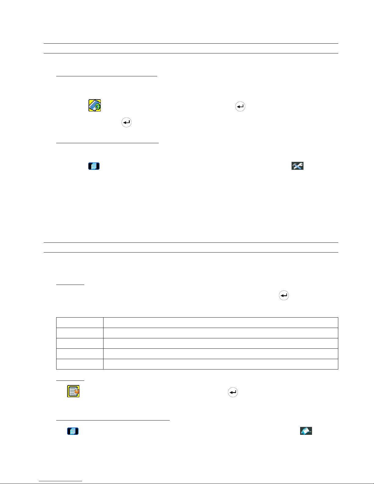
基本操作
-14-
4.5 升級
註:請勿在進行升級時中斷 DVR 電源,否則可能會使得 DVR 功能無法正常運作或無法使用。
‧ 韌體 / 多國語言 OSD 升級
1) 使用 USB 隨身碟進行升級韌體或 OSD。
步驟 1:先將 USB 隨身碟格式化成 FAT 32 的格式。
步驟 2:從您的經銷商取得升級的檔案,並將升級檔案存放在您的 USB 隨身碟中 (請勿變更檔名)。
步驟 3:在 “
” (系統資訊) 目錄選單中,移動游標至 “升級”,並按 (進入) 按鍵進入。
步驟 4:選擇 “是”,並按
(進入) 按鍵確認進行升級。
2) 使用 AP 軟體進行遠端升級韌體或 OSD:
步驟 1:將升級檔案存放至您的電腦 (請勿變更檔名),然後登入 AP 軟體。
步驟 2:按 “ ” (Miscellaneous Control) 按鈕顯示其他功能控制面板。在此控制面板中,按 “ ” (Tools) 按鈕
進入 AP 升級視窗。
步驟 3:輸入 DVR 的使用者名稱、密碼、IP 位址與埠號。
步驟 4:視需要按 “Firmware” (韌體) 或 “Language” (語言) 標籤,然後 “Add” (新增) 按鍵選擇要升級的韌體與
OSD 檔案。
步驟 5:按 “Update Firmware” (更新韌體) 或 “Update Language” (更新語言) 按鍵開始升級。
註:如需得知關於遠端升級的詳細資訊,請參閱第 49 頁的 “Tools (工具)”。
4.6 搜尋
1) 依清單搜尋
按 DVR 正面板上的 “LIST” 按鍵顯示各類型錄影檔案的清單。選擇欲觀看的清單,然後按 (進入) 按鍵開始回
放。
警報 列出所有警報觸發錄影的檔案資訊。
手動 列出所有手動錄影的檔案資訊。只要任何錄影設定變更,DVR 會自動儲存一個錄影檔案。
位移偵測 列出所有位移偵測觸發錄影的檔案資訊。
系統 列出所有系統錄影的檔案資訊。DVR 系統每一小時會儲存一個錄影檔案。
TIMER
列出所有預約錄影的檔案資訊。
2) 依時間搜尋
在 “ ” (事件記錄) 目錄選單中,移動游標至 “快速搜尋”,然後按 (進入) 按鈕進入快速搜尋選單。您可以
依時間搜尋特定事件 (年 / 月 / 日 / 時 / 分) 並直接回放搜尋到的檔案。
3) 使用 AP 軟體的 “Log” 記錄功能搜尋錄影事件
按 “ ” (Miscellaneous Control) 主功能控制按鈕顯示其他功能控制面板。在此控制面板中,按 “ ” (Log) 記
錄按鈕進入 “Log View” (記錄檢視) 頁面。在此記錄檢視頁面中,您會看見不同類型的錄影事件,User (手動錄影) /
Motion (位移偵測錄影) / Alarm (警報錄影),而按 “Play” (播放) 按鈕可直接回放選取檔案。
Page 92

主目錄選單
-15-
5. 主目錄選單
5.1 目錄選單
頻道名稱
事件狀態
狀態
影像大小
錄影品質
錄影設定
錄影張數
預約錄影
預約錄影
預約位移偵測
日期
格式
快速選單
日期
日光節約
攝影機
偵測設定
警報設定
網路設定
顯示設定
進階設定
錄影設定
序列裝置類別
鮑率
本機認證碼
密碼
回復預設值
清除硬碟
升級
自動按鍵鎖 (秒)
語言
系統
系統設定
版本
快速搜尋
硬碟資訊
事件記錄
事件記錄
進階選單
備份 USB 備份
5.2 目錄選單操作
項目 功能
快速選單: 觀看與變更快速選單的設定
目錄選單 進入 / 跳出快速選單
▲ ▼ 選擇 / 變更設定
◄ ► 到上一目錄選單階層或子目錄階層 / 設定值選擇
輸入 確認密碼輸入
進階選單: 在快速選單下,移動游標至 “ ” 圖示,並按 “▼” 按鍵進入進階設定選單。
輸入 進入進階選單的子目錄階層
目錄選單 在進階選單的子目錄選單下,使用此按鍵確認設定並回到上一目錄選單階層。
t 下一個 移動游標至此選項,並按 按鍵進入下一頁面。
s 上一個 移動游標至此選項,並按 按鍵回到上一頁面。
其他進階選單下的操作方式如同快速選單。
Page 93

快速選單
-16-
6. 快速選單
按 (目錄選單) 按鍵並輸入密碼,即可進入快速選單。預設 admin 密碼為 0000。使用者可以稍候再自行變更密
碼。請參閱第 28 頁的 “7.2 系統資訊” 章節。
6.1 狀態顯示
在此目錄選單中,您可以查閱或變更顯示設定。
將游標移到 “ ” 圖示,然後會出現以下畫面:
快速選單
頻道名稱
ON
事件狀態
ON
影像大小
CIF
錄影品質 最佳
錄影張數
120
預約錄影
OFF
預約位移偵測
OFF
日期
2007 / 08 / 08 21 : 30 : 00
格式 年 / 月 / 日
日光節約
OFF
進階 uv 選取 s 上一個 t 下一個 進入
子目錄選單的選項解說如下:
1) 頻道名稱
選擇是否顯示頻道的名稱 (開/關)。
2) 事件狀態
選擇是否顯示代表特定事件的圖示 (ON / OFF)。
Page 94

快速選單
-17-
6.2 手動錄影
在此功能選單下,您可以進行錄影功能的設定。
將游標移到 “ ” 圖示,然後會出現以下畫面:
快速選單
頻道名稱
ON
事件狀態
ON
影像大小
CIF
錄影品質 最佳
錄影張數
120
預約錄影
OFF
預約位移偵測
OFF
日期
2007 / 08 / 08 21 : 30 : 00
格式 年 / 月 / 日
日光節約
OFF
進階 uv 選取 s 上一個 t 下一個 進入
子目錄選單的選項解說如下:
1) 影像大小
選擇其中一種錄影影像大小:FRAME、FIELD 或 CIF。
2) 錄影品質
選擇下列 4 個品質錄影選項:最佳、高、一般和基本。
3) 錄影張數
選擇手動錄影的 IPS (每秒播放圖像的速度)。選項如下:
NTSC IPS PAL IPS
FRAME
3、7、15、30
FRAME
3、6、12、25
FIELD
7、15、30、60
FIELD
6、12、25、50
CIF
15、30、60、120
CIF
12、25、50、100
6.3 預約錄影
在此功能選單下,您可以設定不同的時間組來進行錄影或啟動位移偵測功能。
Page 95

快速選單
-18-
將游標移到 “ ” 圖示,然後會出現以下畫面:
快速選單
頻道名稱 ON
事件狀態 ON
影像大小 CIF
錄影品質 最佳
錄影張數 120
預約錄影 OFF
預約位移偵測 OFF
日期 2007 / 08 / 08 21 : 30 : 00
格式 年 / 月 / 日
日光節約 OFF
進階 uv 選取 s 上一個 t 下一個 進入
子目錄選單的選項解說如下:
1) 預約錄影
按 ▲ / ▼ 按鍵可變更設定 (ON / OFF)。若此功能設為 “ON” (開),請按輸入鍵進入子目錄選項來進行進一步的設
定。
預約錄影
0 2 4 6 8 10 12 14 16 18 20 22 24
星期日
星期一
星期二
星期三
星期四
星期五
星期六
進階設定請聯絡與諮詢您的安裝商
uv s t 移動 選擇
X 軸:0 ~ 24 小時。每個時間方塊為 2 小時,再細分為四個小方塊,每個小方塊分別為 30 分鐘。
Y 軸:星期一 ~ 星期日。
操作說明:將游標移到要開始的時間點,然後按輸入鍵設定開始時間點 (標示為紅色)。接著,按 ▲ ▼◄ ► 鍵來
設定預約錄影時程。設定完畢後,再按一下輸入鍵設定結束時間點 (標示為黃色),然後按 (目錄選單) 鍵退出。
2) 預約偵測錄影
按 ▲ / ▼ 按鍵可變更設定 (ON / OFF)。若此功能設為 “ON” (開),請按輸入鍵進入子目錄選項來進行進一步的設
定。
Page 96

快速選單
-19-
預約位移偵測
0 2 4 6 8 10 12 14 16 18 20 22 24
星期日
星期一
星期二
星期三
星期四
星期五
星期六
進階設定請聯絡與諮詢您的安裝商
uv s t 移動 選擇
X 軸:0 ~ 24 小時。每個時間方塊為 2 小時,再細分為四個小方塊,每個小方塊分別為 25 分鐘。
Y 軸:星期一 ~ 星期日。
操作說明:將游標移到要開始的時間點,然後按輸入鍵設定開始時間點 (標示為紅色)。接著,按 ▲ ▼◄ ► 鍵來
設定預約錄影時程。設定完畢後,再按一下輸入鍵設定結束時間點 (標示為黃色),然後按 (目錄選單) 鍵退出。
註:此處僅為設定與啟動預約位移偵測功能。如需得知設定與啟動位移偵測功能的資訊,請參閱第 22 頁的 “7.1.2 位
移偵測設定” 章節。
6.4 日期
在此目錄選單中,您可以設定 DVR 系統日期與時間。
按下 (目錄選單) 按鍵,可進入主目錄選單。將游標移到 “ ” 圖示,然後會出現以下畫面:
快速選單
頻道名稱 ON
事件狀態 ON
ON
影像大小 CIF
錄影品質 最佳
錄影張數 120
預約錄影 OFF
預約位移偵測 OFF
日期 2007 / 08 / 08 21 : 30 : 00
格式 年 / 月 / 日
日光節約 OFF
進階 uv 選取 s 上一個 t 下一個 進入
Page 97

快速選單
-20-
子目錄選單的選項解說如下:
1) 日期
設定日期與時間。預設的顯示順序為 “年–月–日 時 : 分 : 秒”。
2) 格式
選擇下列 3 種的日期顯示格式:年-月-日 / 月-日-年 / 日-月-年。
3) 日光節約
按 ▲ / ▼ 按鍵選擇是否要使用日光節約功能 (ON / OFF)。若此功能設為 “ON” (開),請按輸入鍵進入子目錄選項
來進行進一步的設定。
日光節約
開始時間
第四個 – 星期日 – 三月 24 : 00 : 00
結束時間
第四個 - 星期日 - 十月 24: 00 : 00
調整
01 : 00
進階設定請聯絡與諮詢您的安裝商
uv 選擇 s 上一個 t 下一個 進入
設定開始時間與結束時間,並設定日光節約時間的調整時數。上述的例子是指在日光節約期間 (自 3 月第 4 個星期
日開始,至 10 月第 4 個星期日結束),DVR 的系統時間會+1 小時。設定完畢後,再按一下輸入鍵設定結束時間點,然
後按 (目錄選單) 鍵退出。
註:若時間日期設定完畢,重新開機後卻又回復到出廠設定值,此時請將 DVR 連續上電 24~48 小時後,再觀察是否還
有此情形發生。
Page 98

進階選單
~21~
7. 進階選單 (以 16 路 DVR 為例)
按 按鍵並輸入密碼,即可進入快速選單。將游標移到 “進階”,即可進入進階選單。預設 admin 密碼為 0000。
使用者可以稍候再自行變更密碼。請參閱第 28 頁的 “7.2 系統資訊” 章節。
若要設定此進階選單,建議請洽詢您的安裝商。
7.1 進階選單設定
在此功能選單下,您可以查看或變更攝影機 / 位移偵測設定 / 警示音設定 / 網路設定 / 顯示設定的設定。
將游標移到 “ ” (進階選單) 圖示,然後會出現以下畫面:
進階選單
攝影機
位移偵測設定
警示音設定
網路設定
顯示設定
錄影設定
進階設定請聯絡與諮詢您的安裝商
uv 選擇 s 上一個 t 下一個 進入
7.1.1 攝影機
在此子目錄選單中,您可以進行進階攝影機設定,例如攝影機名稱或調整亮度。將游標移到 “攝影機設定” 的選項,
然後按 ” ” (輸入) 鍵確認。您將會看到類似以下的選項:
攝影機
名稱 亮度 對比 飽和 色相 隱蔽 錄影
CH1 128 098 128 128 OFF ON
CH2 128 098 128 128 OFF ON
CH3 128 098 128 128 OFF ON
CH4 128 098 128 128 OFF ON
CH5 128 098 128 128 OFF ON
CH6 128 098 128 128 OFF ON
CH7 128 098 128 128 OFF ON
CH8 128 098 128 128 OFF ON
CH9 128 098 128 128 OFF ON
CH10 128 098 128 128 OFF ON
CH11 128 098 128 128 OFF ON
CH12 128 098 128 128 OFF ON
下一個
進階設定請聯絡與諮詢您的安裝商
uv 選擇 s 上一個 t 下一個 進入
子目錄選單的選項解說如下。在變更攝影機設定時,您可以從螢幕上預覽 變更的結果。
Page 99

進階選單
~22~
1) 名稱
您可以在此變更預設的攝影機名稱。預設的攝影機名稱為頻道號碼。
移動游標到您希望改變名稱的頻道,然後按一下 DVR 控制面板的 “ ” (輸入) 進入字元選取畫面。選定攝影機名
稱,最多六個字元 (字母或符號或數字)。
2) 亮度 / 對比 / 飽和 / 色相
您可以在此調整各頻道的亮度/對比/飽和度/色相。預設的對比值為 098,其他項目的預設值為 128。數值必須介於
0 到 255 之間。
3) 隱蔽
選擇是否要隱藏選取頻道的畫面 (ON / OFF)。當此功能啟動後,在該選取頻道的螢幕上會出現 “隱蔽” 的字樣。
4) 錄影
選擇是否要啟動選擇頻道的錄影功能 (ON / OFF)。當此功能啟動後,在該選取頻道的螢幕上會出現 “ ” 圖示。
7.1.2 位移偵測設定
在此子目錄選單中,您可以設定與位移偵測相關的功能。
將游標移到 “位移偵測設定”,然後按 ” ” (輸入) 鍵確認。您將會看到類似以下的選項:
位移偵測設定
名稱 偵測 區域
LS SS TS RE
警報
CH1 OFF
設定
07 03 02 10 OFF
CH2 OFF
設定
07 03 02 10 OFF
CH3 OFF
設定
07 03 02 10 OFF
CH4 OFF
設定
07 03 02 10 OFF
CH5 OFF
設定
07 03 02 10 OFF
CH6 OFF
設定
07 03 02 10 OFF
CH7 OFF
設定
07 03 02 10 OFF
CH8 OFF
設定
07 03 02 10 OFF
CH9 OFF
設定
07 03 02 10 OFF
CH10 OFF
設定
07 03 02 10 OFF
下一個
進階設定請聯絡與諮詢您的安裝商
uv 選擇 s 上一個 t 下一個 進入
子目錄選單的選項解說如下:
1) 名稱
顯示每個頻道的攝影機名稱 (在 “攝影機” 目錄選單中設定)。
2) 偵測
選擇是否啟動該選擇頻道的位移偵測功能 (ON/OFF)。
3) 區域
每隻攝影機的偵測區域分為 16 * 12 (192) 方格。粉紅色格子代表未被偵測的區域,而透明的格子代表有偵測的區
域。
按下 DVR 控制面板的
(輸入) 鍵來設定位移偵測區域。您將會看到類似以下的畫面:
Page 100

進階選單
~23~
透明方格表示未偵測區域。
按 (輸入) 鍵確認開始區域。
按 ◄ / ► 鍵選擇偵測區域的寬度。
按 ▲ / ▼ 鍵選擇偵測區域的高度。 您也可以設定多個偵測區域。
當偵測到任何動作時,您會看見
方格在閃動。
4) LS (靈敏程度)
“LS” 是比較兩張不同影像的靈敏度。數值越小,位移偵測的靈敏度越高。最高靈敏度設定值是 00,最低靈敏度設
定值是 15。預設值是 07。
5) SS (空間靈敏度)
“SS” 是偵測螢幕上物體大小 (位移偵測的格子數目) 的靈敏度。數值越小,位移偵測的靈敏度越高。
最高靈敏度設定值是 00,最低靈敏度設定值是 15。預設值是 03。
註:SS 的預設值為 03,意指若被偵測的物體若在螢幕上超過 3 格,將會觸發位移偵測。故 SS 數值必須比您所設定的
位移偵測格數還要少。
6) TS (時間靈敏度)
“TS” 是物體持續觸發位移偵測的時間長短的靈敏度。數值越小,位移偵測的靈敏度越高。
最高靈敏度設定值是 00,最低靈敏度設定值是 15。預設值是 02。
7) RE (靈敏度參考值)
“RE” 是位移偵測的參考數值。預設值 10 代表 DVR 會依照 LS、SS、TS 的設定一次同時比較 10 張圖片。
數值越大,位移偵測的靈敏度越高。最高的靈敏度數值為 61。
8) 警報
以外接警報設備的 Alarm Polarity 為依據,來選擇將此選項設定為 N.O. / N.C.。預設值為 OFF (關)。
7.1.3 警示音設定
在此目錄選單中,您可以設定所有不同情形下的警示音,例如當硬碟即將錄滿的時候發出警示音。
 Loading...