

Page 1
5/3/2-MEGA PIXELS NETWORK CAMERA
U
SER MENU
IR
-
5/2MIPN/2MIPS/3M
IP
W42
Version: V1.3
Doc. No.: 103022001
IR-5MIP566/ IR-3MIP566
Page 2

Safety information
This symbol indicates that dangerous voltage consisting a risk of electric shock is
present within this unit. Megapixels
This exclamation point symbol is intended to alert the user to the presence of important
operating and maintenance (servicing) instructions in the literature accompanying the
appliance.
WARNING
To prevent damage that may result in fire or electric shock hazard, do not expose this
appliance to rain or moisture.
To prevent injury, this apparatus must be securely attached to the floor / wall in accordance
with the installation instructions.
WARNING
1. Be sure to use only the standard adapter that is specified in the specification sheet using any
other adapter could cause fire, electric shock, or damage to the product.
2. Incorrectly connecting the power supply or replacing battery may cause explosion, fire,
electric shock, or damage to the product.
3. Do not connect multiple cameras to a single adapter. Exceeding the capacity may cause
the abnormal heat generation or fire.
4. Securely plug the power cord into the power receptacle, insecure connection may cause fire.
5. When installing the camera, fasten it securely and firmly. The fall of camera may cause
personal injury.
6. Do not place conductive objects (e.g. screwdrivers, coins, metal parts, etc.) or containers
2
Page 3

filled with water on top of the camera. Doing so may cause personal injury due to fire,
electric shock, or falling objects.
7. If any unusual smells or smoke come from the unit, stop using the product. In such case,
immediately disconnect the power source and contact the service center. Continued use in
such a condition may cause fire or electric shock.
8. If this product fails to operate normally, contact the nearest service center and never
disassemble or modify this product in any way. (I-View is not liable for problems caused by
unauthorized modifications or attempted repair.)
9. When cleaning, do not spray water directly onto parts of the product. Doing so may cause
fire or electric shock.
CAUTION
Do not drop objects on the product or apply strong shock to it. Keep away from a location
subject to excessive vibration or magnetic interference.
Do not install in a location subject to high temperature (over 50°C), low temperature (below
-10°C), or high humidity. Doing so may cause fire or electric shock.
If you want to relocate the already installed product, be sure to turn off the power and then
move or reinstall it.
Remove the power plug from the outlet when then there is a lightning. Neglecting to do so
may cause fire or damage to the product.
Keep out of direct sunlight and heat radiation sources. It may cause fire.
Install it in a place with good ventilation.
Avoid aiming the camera directly towards extremely bright objects such as sun, as this may
damage the CCD image sensor.
Apparatus shall not be exposed to dripping or splashing and no objects filled with liquids,
such as vases, shall be placed on the apparatus.
The Mains plug is used as a disconnect device and shall stay readily operable at any time.
Do not expose the camera to radioactivity. Radioactivity exposure may damage the CCD.
3
Page 4

IMPORTANT SAFETY INSTRUCTIONS
Read these instructions.
Keep these instructions.
Heed all warnings.
Follow all instructions.
Do not use this apparatus near water.
Clean only with dry cloth.
Do not block any ventilation openings. Install in accordance with the manufacturer’s
instructions.
Do not install near any heat sources such as radiators, heat registers, or other apparatus
(Including amplifiers) that produce heat.
Do not defeat the safety purpose of the polarized or grounding-type plug. A polarized plug
has two blades with one wider than the other. A grounding type plug has two blades and a
third grounding prong. The wide blade or the third prong is provided for your safety. If the
provided plug does not fit into your outlet, consult an electrician for replacement of the
obsolete outlet.
Protect the power cord from being walked on or pinched particularly at plugs, convenience
receptacles, and the point where they exit from the apparatus.
Only use attachments/accessories specified by the manufacturer.
Use only with cart, stand, tripod, bracket, or table specified by the
manufacturer, or sold with the apparatus.
Unplug this apparatus when a card is used. Use caution when moving the cart/ apparatus
combination to avoid injury from tip-over.
Refer all servicing to qualified service personnel. Servicing is required when the apparatus
has been damaged in any way, such as power supply cord or plug is damaged, liquid has
been spilled or objects have fallen into the apparatus, the apparatus has been exposed to rain
or moisture, does not operate normally, or has been dropped.
Apparatus shall not be exposed to dripping or splashing and no objects filled with liquids,
such as vases, shall be placed on the apparatus.
4
Page 5

SAFETY INFORMATION
FCC STATEMENT
This device complies with part 15 of the FCC Rules. Operation is subject to the following
conditions:
1. This device may not cause harmful interference, and
2. This device must accept any interference received including interference that may cause
undesired operation.
CAUTION
This equipment has been tested and found to comply with the limits for a Class A digital
device, pursuant to part 15 of FCC Rules. These limits are designed to provide reasonable
protection against harmful interference when the equipment is operated in a commercial
environment.
This equipment generates, uses, and can radiate radio frequency energy and, if not installed
and used in accordance with the instruction manual, may cause harmful interference to radio
communications. Operation of this equipment in a residential area is likely to cause harmful
interference in which case the user will be required to correct the interference at his own
expense.
Correct Disposal of This Product (Waste Electrical & Electronic Equipment)
This marking on the product, accessories or literature indicates that the product and its
electronic accessories should not be disposed of with other household waste at the end of their
working life. To prevent possible harm to the environment or human health from uncontrolled
waste disposal, please separate these items from other types of waste and recycle them
responsibly to promote the sustainable reuse of material resources.
Household users should contact either the retailer where they purchased this product, or their
local government office, for details of where and how they can take these items for
environmentally safe recycling.
Business users should contact their supplier and check the terms and
conditions of the purchase contract. This product and its electronic
accessories should not be mixed with other commercial wastes for disposal.
5
Page 6

About This Guide
Conventions used in this guide
To make sure that you perform certain tasks properly, take note of the following symbols to use
throughout this manual.
WARNING: Information to prevent injury to yourself when trying to complete a task.
CAUTION: Information to prevent damage to the components when trying to complete a
task.
IMPORTANT: Information that you must follow to complete a task.
NOTE: Tips and additional information to aid in completing a task.
Trademark
I-View, e-Witness, @-Witness Pro, u-Witness XP, x-Witness, FreeView Pro, AnyCam, PDAVirw
and MobileView are registered trademarks of I-View Communication Inc.
Microsoft, Windows 95, 98, ME, Windows2000, XP, Vista, 7 and 8 are registered trademarks of
Microsoft Corporation. All other trademarks are the property of their respective holders.
Customer Support
If technical problems arise with the use of our products in which you and your vendor cannot
resolve, please try the following: If you have an Internet connection, visit the I-View website
http://www.i-view.com.tw (Taiwan) for any software or product updates, or email to
support@i-view.com.tw (Taiwan) or Tel: 886-3-510-3001 Fax: 886-3-510-3002 (Taiwan). We
are dedicated to providing the highest quality support. E-mailing our tech support will give you
the chance to document each of the above items in a very clear and concise manner and will give
our support team a chance to document any problems and respond with thoroughly researched
answers.
6
Page 7

Table of Contents
Chapter 1. Introduction ---------------------------------------------------------------------------------------- 8
1-1. Highlights of your new Network IP Camera ------------------------------------------------ 8
1-2. Product Specification --------------------------------------------------------------------------- 9
1-3. Packaging Contents --------------------------------------------------------------------------- 18
1-4. Product Dimension ---------------------------------------------------------------------------- 18
1-5. Product Parts Description -------------------------------------------------------------------- 19
Chapter 2. Camera Installation------------------------------------------------------------------------------ 21
2-1. Wall Mount installation ----------------------------------------------------------------------- 21
Chapter 3. Running IP Camera by Witness Pro NVR software ------------------------------------- 23
3-1. Network Deployment ------------------------------------------------------------------------- 23
3-2. Install Witness Pro NVR software ---------------------------------------------------------- 24
3-3. Setting IP camera for Witness Pro NVR software ---------------------------------------- 26
Chapter 4. Running IP Camera by I.E. Browser -------------------------------------------------------- 29
4-1. Install ActiveX Plug-in on I.E. Browser --------------------------------------------------- 30
4-2. The Function Description of Live Window ----------------------------------------------- 33
4-3. The Network setup Function Description-------------------------------------------------- 35
Chapter 5. Troubleshooting ---------------------------------------------------------------------------------- 54
7
Page 8

Chapter 1. Introduction
1-1. Highlights of your new Network IP Camera
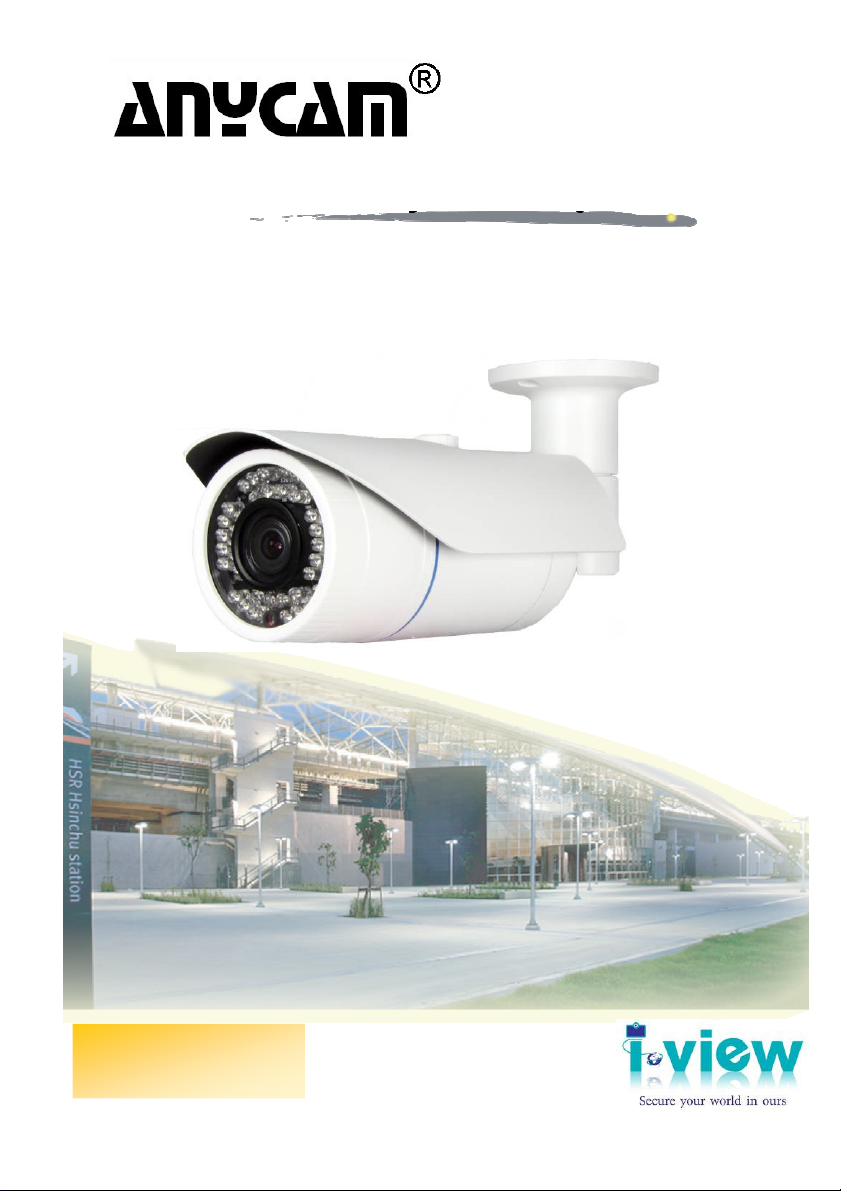
Congratulates on purchasing this high-resolution 5M pixels network IP Camera! This IP Camera
provides 5-Mega pixels high-resolution video quality, with its advanced megapixel lens; you can
view remote images in more detail than conventional close-circuit cameras.
Other highlights of this network IP Camera include:
Onvif compliant.
Built-in 802.3af compliant PoE
Two way audio support.
IP67 waterproofing criterion.
Built-in 3~9 mm Vari-focal Lens.
3GPP mobile surveillance support.
Anti-cut cable and 3-Axis bracket design.
Built-in 42 pieces IR-LED Illuminators.
Up to 5-Megapixels (2048×1536) video resolution .
Support motion detection and video output.
Built-in surge protector best for outdoor usage.
Removable IR-cut filter for Day & Night function.
H.264 and MJPEG multiple simultaneous streams.
Support Wide Dynamic Range and Privacy mask function.
Ultra Low Compress Rate(ULCR) technology: LESS storage space, SAME video quality.
ROI (Region of Interest) encoding enhances the quality of specified images.
8
Page 9

1-2. Product Specification
IR-5MIPN42 Series
System
Platform: TI DM368 SoC CPU; Linux Embedded O.S.
Image Device
1/2.5" 5 M pixels (2592x 1944 pixels) progressive CMOS sensor.
Video Setting
Compression: Video: 0.1M ~ 12M bits/sec (CBR/VBR/LBR configurable) H.264
HP/MP/BP, M-JPEG; Audio: G.711μ-low/a-low Codec
Resolution: Main Streaming: 2592×1920, 2048×1536, 1920×1080, 1280×720. Sub
streaming: 320×288, 320*240
Frame Rate: 5-Mega: 10 fps; 3-Mega: 20 fps; 1080p: 30 fps @ H.264/M-JPEG Mode; Frame
rate can be adjustable by user.
Streaming: Multi-Stream H.264 Base/Main/High Profile and Motion JPEG video streaming
Control: Brightness, Contrast, Saturation, Sharpness, Exposure, Motion detection, Mirror,
Shutter, Privacy mask, Flickerless, Noise reduction, IRIS, AES , AWB, AGC , BL C,
D- WD R, ROI, Audio ga in, Alarm in/o ut
Color: 0.5 Lux 1/F1.2 B/W: 0 Lux. (IR LED on)
D- WD R: 70dB
Overlay: Text / Time Stamp
Audio Setting
μ
-Low/ a-Low G.711 audio encoding and decoding; 2-way audio.
External Microphone input; Speaker output.
2Vp-p audio input and audio output with 600Ω impedance.
Network
Protocol: HTTP, HTTPS, TCP/ IP, IPv4, IPv6, UDP, SMTP, FTP, DHCP, DDNS, NTP,
DNS, SNMP, RTSP, RTP/RTCP, Bonjour, PPPoE, QoS, UPnP, IGMP; uPnP and 802.1x.
Interface: 10BASE-T/100 BASE-TX; Wi-Fi (Via USB optional)
Compatible: Onvif compliant.
9
Page 10
I/O Port
Stand ar d: Audio in (2 Vp -p ); Audio o ut ( 30 mW/600Ω); DC power in, RJ-45
(LED indicates power /linking status).
Fu ll function : Ala rm in x1; Alarm out x1; TV out, Reset button, Video out, SD Card
slot. (IR-5MIPN42-Fxxxx-F)
Option: USB for Wi-Fi device
Surge Protector
Video : Pe ak Inverse Bl oc king Volt ag e: VPIB = 10 0V; Peak P ul se Curren t:
Ip p= 44 A; Clampi ng Voltage: 1 0V @ Ipp= 5 A.
Po we r: Maximum En ergy: 3 .6 J @10/1000µs; C la mping Vol ta ge:
16 .8 KA(1-Ti me)/8.4KA(2 -Time s) @8/20µs (1 Time ); Insulation R es istance:
10 00 0MΩ.
≧
Lens & IR Illuminators
Lens: f=3〜9 mm/ F1.2〜F2.3 (IR-5MIPN42-F0309 & IR-5MIPN42-F0309-F );
f=2.8〜12 mm/ F1.2〜F2.8 (IR-5MIPN42-F0312 & IR-5MIPN42-F0312-F );
f= 4mm; 6mm, 8mm, 12mm/ F1.8 (Optional) (IR-5MIPN42-F04/06/08/12).
IR Cut: Built on removable IR-cut filter for day & night function.
IR Illuminators: 42 pieces I R LED Illuminators.
Storage
Micro SD slot for SD/SDHC card storage; Support Pre-recording and Post recording; Network
failed start recording on SD card, Backup/Restore to device configuration file, Backup, Upload
data to FTP/SMTP sever.
Management
Time management: Manual Time Setting; Time Server and NTP support; Real Time Clock.
Event management: Events triggered by motion detection or sensor configured by schedule.
Event notification: Notify to FTP, email, Samba server or Digital output triggered.
Update: Support Firmware update.
Browse
I.E. 7.0 above; Safair Browser, Firefox and Chrome V3.0 above with plug in.
10
Page 11

Housing
Waterproof IP67 housing with anti-cut cable and 3-Axis bracket.
Dimension/Weight
310mm (L) x 100 mm (W) x 85 mm (H) / 0.98Kg; (Including bracket).
Operation
Power: Maximum 3 W & 8W(IR LED On); PoE IEEE 802.3af Class 3; DV12V
Temper at ure: Temperature -10°C ~ 50°C; Humidity 20% ~ 80% RH.
IR-2MIPN42 Series
System
Platform: TI DM365 SoC CPU; Linux Embedded O.S.
Image Device
1/3" 1.3 M pixels (1280x 960 pixels) progressive CMOS sensor.
Video Setting
Compression: Video: 0.1M ~ 8M bits/sec (CBR/VBR/LBR configurable) H.264 HP/MP/BP,
M-JPEG; Audio: G.711μ-low/a-low Codec
Resolution: Main Streaming: 1920X1080 (Software enhance), 1280×960, 1280×720.
Sub streaming: 320×288, 320*240
Frame Rate: 2-Mega: 20 fps (Software enhance); 1.3Mega: 30 fps @ H.264/M-JPEG Mode;
Frame rate can be adjustable by user.
Streaming: Multi-Stream H.264 Base/Main/High Profile and Motion JPEG video streaming
Control: Brightness, Contrast, Saturation, Sharpness, Exposure, Motion detection, Mirror,
Shutter, Privacy mask, Flickerless, Noise reduction, IRIS, AES , AWB, AGC , BL C,
D- WD R, ROI, Audio ga in, Alarm in/o ut
Color: 0.1 Lux 1/F1.2 B/W: 0 Lux.. (IR LE D on)
D- WD R: 83.5dB
Overlay: Text / Time Stamp
Audio Setting
μ
-Low/ a-Low G.711 audio encoding and decoding; 2-way audio.
11
Page 12
External Microphone input; Speaker output.
2Vp-p audio input and audio output with 600Ω impedance.
Network
Protocol: HTTP, HTTPS, TCP/ IP, IPv4, IPv6, UDP, SMTP, FTP, DHCP, DDNS, NTP,
DNS, SNMP, RTSP, RTP/RTCP, Bonjour, PPPoE, QoS, UPnP, IGMP; uPnP and 802.1x.
Interface: 10BASE-T/100 BASE-TX; Wi-Fi (Via USB optional)
Compatible: Onvif compliant.
I/O Port
Stand ar d: Audio in (2 Vp -p ); Audio o ut ( 30 mW/600Ω); DC power in, RJ-45
(LED indicates power /linking status).
Fu ll function : Ala rm in x1; Alarm out x1; TV out, Reset button, Video out, SD Card
slot. (IR-2MIPN42-Fxxxx-F)
Option: USB for Wi-Fi device
Surge Protector
Video : Pe ak Inverse Bl oc king Volt ag e: VPIB = 10 0V; Peak P ul se Curren t:
Ip p= 44 A; Clampi ng Voltage: 1 0V @ Ipp= 5 A.
Po we r: Maximum En ergy: 3 .6 J @10/1000µs; C la mping Vol ta ge:
16 .8 KA(1-Ti me)/8.4KA(2 -Time s) @8/20µs (1 Time ); Insulation R es istance:
10 00 0MΩ.
≧
Lens & IR Illuminators
Lens: f=2.8〜12 mm/ F1.2〜F2.8 (IR-2MIPN42-F0312 & IR-2MIPN42-F0312-F );
f= 4mm; 6mm, 8mm, 12mm/ F1.8 (Optional) (IR-2MIPN42-F04/06/08/12).
IR Cut: Built on removable IR-cut filter for day & night function.
IR Illuminators: 42 pieces I R LED Illuminators.
Storage
Micro SD slot for SD/SDHC card storage; Support Pre-recording and Post recording; Network
failed start recording on SD card, Backup/Restore to device configuration file, Backup, Upload
data to FTP/SMTP sever.
Management
12
Page 13

Time management: Manual Time Setting; Time Server and NTP support; Real Time Clock.
Event management: Events triggered by motion detection or sensor configured by schedule.
Event notification: Notify to FTP, email, Samba server or Digital output triggered.
Update: Support Firmware update.
Browse
I.E. 7.0 above; Safair Browser, Firefox and Chrome V3.0 above with plug in.
Housing
Waterproof IP67 housing with anti-cut cable and 3-Axis bracket.
Dimension/Weight
310mm (L) x 100 mm (W) x 85 mm (H) / 0.98Kg; (Including bracket).
Operation
Power: Maximum 2.5 W & 8 W(IR LED On); PoE IEEE 802.3af Class 3; DV12V
Temper at ure: Temperature -10°C ~ 50°C; Humidity 20% ~ 80% RH.
IR-2MIPS42 Series
System
Platform: TI DM368 SoC CPU; Linux Embedded O.S.
Image Device
1/3" 2M pixels (1920X1080 pixels) SONY Exmor progressive CMOS sensor.
Video Setting
Compression: Video: 0.1M ~ 12M bits/sec (CBR/VBR/LBR configurable) H.264
HP/MP/BP, M-JPEG; Audio: G.711 μ-low/a-low Codec
Resolution: Main Streaming: 1920×1080. Sub streaming: 320×288, 320*240
Frame Rate: 1080p: 30 fps @ H.264/M-JPEG Mode; Frame rate can be adjustable by user.
Streaming: Multi-Stream H.264 Base/Main/High Profile and Motion JPEG video streaming
Control: Brightness, Contrast, Saturation, Sharpness, Exposure, Motion detection, Mirror,
Shutter, Privacy mask, Flickerless, Noise reduction, IRIS, AES , AWB, AGC , BL C,
D- WD R, ROI, Audio ga in, Alarm in/o ut
Color: 0.3 Lux 1/F1.2 B/W: 0.1 Lux. (IR LED on) .
13
Page 14
D- WD R: 76dB
Overlay: Text / Time Stamp
Audio Setting
μ
-Low/ a-Low G.711 audio encoding and decoding; 2-way audio.
External Microphone input; Speaker output.
2Vp-p audio input and audio output with 600Ω impedance.
Network
Protocol: HTTP, HTTPS, TCP/ IP, IPv4, IPv6, UDP, SMTP, FTP, DHCP, DDNS, NTP,
DNS, SNMP, RTSP, RTP/RTCP, Bonjour, PPPoE, QoS, UPnP, IGMP; uPnP and 802.1x.
Interface: 10BASE-T/100 BASE-TX; Wi-Fi (Via USB optional)
Compatible: Onvif compliant.
I/O Port
Stand ar d: Audio in (2 Vp -p ); Audio o ut ( 30 mW/600Ω); DC power in, RJ-45
(LED indicates power /linking status).
Fu ll function : Ala rm in x1; Alarm out x1; TV out, Reset button, Video out, SD Card
slot. (IR-2MIPS42-Fxxxx-F)
Option: USB for Wi-Fi device
Surge Protector
Video : Pe ak Inverse Bl oc king Volt ag e: VPIB = 10 0V; Peak P ul se Curren t:
Ip p= 44 A; Clampi ng Voltage: 1 0V @ Ipp= 5 A.
Po we r: Maximum En ergy: 3 .6 J @10/1000µs; C la mping Vol ta ge:
16 .8 KA(1-Ti me)/8.4KA(2 -Time s) @8/20µs (1 Time ); Insulation R es istance:
10 00 0MΩ.
≧
Lens & IR Illuminators
Lens: f=3〜9 mm/ F1.2〜F2.3 (IR-2MIPS42-F0309 & IR-2MIPS42-F0309-F );
f=2.8〜12 mm/ F1.2〜F2.8 (IR-2MIPS42-F0312 & IR-2MIPS42-F0312-F );
f= 4mm; 6mm, 8mm, 12mm/ F1.8 (Optional) (IR-2MIPS42-F04/06/08/12).
IR Cut: Built on removable IR-cut filter for day & night function.
IR Illuminators: 42 pieces I R LED Illuminators.
14
Page 15

Storage
Micro SD slot for SD/SDHC card storage; Support Pre-recording and Post recording; Network
failed start recording on SD card, Backup/Restore to device configuration file, Backup, Upload
data to FTP/SMTP sever.
Management
Time management: Manual Time Setting; Time Server and NTP support; Real Time Clock.
Event management: Events triggered by motion detection or sensor configured by schedule.
Event notification: Notify to FTP, email, Samba server or Digital output triggered.
Update: Support Firmware update.
Browse
I.E. 7.0 above; Safair Browser, Firefox and Chrome V3.0 above with plug in.
Housing
Waterproof IP67 housing with anti-cut cable and 3-Axis bracket.
Dimension/Weight
310mm (L) x 100 mm (W) x 85 mm (H) / 0.98Kg; (Including bracket).
Operation
Power: Maximum 3 W & 8W(IR LED On); PoE IEEE 802.3af Class 3; DV12V
Temper at ure: Temperature -10°C ~ 50°C; Humidity 20% ~ 80% RH.
IR-3MIPW42 Series
System
Platform: TI DM368 SoC CPU; Linux Embedded O.S.
Image Device
1/3" 3 M pixels (2048x 1536 pixels) progressive CMOS sensor.
Video Setting
Compression: Video: 0.1M ~ 12M bits/sec (CBR/VBR/LBR configurable) H.264
HP/MP/BP, M-JPEG; Audio: G.711μ-low/a-low Codec
Resolution: Main Streaming: 2048×1536, 1920×1080, 1280×720.
15
Page 16

Sub streaming: 320×288, 320*240
Frame Rate: 3-Mega: 20 fps; 1080p: 30 fps @ H.264/M-JPEG Mode; Frame rate can be
adjustable by user.
Streaming: Multi-Stream H.264 Base/Main/High Profile and Motion JPEG video streaming
Control: Brightness, Contrast, Saturation, Sharpness, Exposure, Motion detection, Mirror,
Shutter, Privacy mask, Flickerless, Noise reduction, IRIS, AES , AWB, AGC , BL C, WDR,
RO I, Au dio gain, Alar m in /out
Color: 0.2 Lux 1/F1.2 B/W: 0 Lux. (IR LED on) .
WD R: 83.5dB
Overlay: Text / Time Stamp
Audio Setting
μ
-Low/ A-Low G.711 audio encoding and decoding; 2-way audio.
External Microphone input; Speaker output.
2Vp-p audio input and audio output with 600Ω impedance.
Network
Protocol: HTTP, HTTPS, TCP/ IP, IPv4, IPv6, UDP, SMTP, FTP, DHCP, DDNS, NTP,
DNS, SNMP, RTSP, RTP/RTCP, Bonjour, PPPoE, QoS, UPnP, IGMP; uPnP and 802.1x.
Interface: 10BASE-T/100 BASE-TX; Wi-Fi (Via USB optional)
Compatible: Onvif compliant.
I/O Port
Stand ar d: Audio in (2 Vp -p ); Audio o ut ( 30 mW/600Ω); DC power in, RJ-45
(LED indicates power /linking status).
Fu ll function : Ala rm in x1; Alarm out x1; TV out, Reset button, Video out, SD Card
slot. (IR-3MIPW42-Fxxxx-F)
Option: USB for Wi-Fi device
Surge Protector
Video : Pe ak Inverse Bl oc king Volt ag e: VPIB = 10 0V; Peak P ul se Curren t:
Ip p= 44 A; Clampi ng Voltage: 1 0V @ Ipp= 5 A.
Po we r: Maximum En ergy: 3 .6 J @10/1000µs; C la mping Vol ta ge:
16
Page 17

16 .8 KA(1-Ti me)/8.4KA(2 -Time s) @8/20µs (1 Time ); Insulation R es istance:
10 00 0MΩ.
≧
Lens & IR Illuminators
Lens: f=3〜9 mm/ F1.2〜F2.3 (IR-3MIPW42-F0309 & IR-3MIPW42-F0309-F );
f=2.8〜12 mm/ F1.2〜F2.8 (IR-3MIPW42-F0312 & IR-3MIPW42-F0312-F );
f= 4mm; 6mm, 8mm, 12mm/ F1.8 (Optional) (IR-3MIPW42-F04/06/08/12).
IR Cut: Built on removable IR-cut filter for day & night function.
IR Illuminators: 42 pieces I R LED Illuminators.
Storage
Micro SD slot for SD/SDHC card storage; Support Pre-recording and Post recording; Network
failed start recording on SD card, Backup/Restore to device configuration file, Backup, Upload
data to FTP/SMTP sever.
Management
Time management: Manual Time Setting; Time Server and NTP support; Real Time Clock.
Event management: Events triggered by motion detection or sensor configured by schedule.
Event notification: Notify to FTP, email, Samba server or Digital output triggered.
Update: Support Firmware update.
Browse
I.E. 7.0 above; Safair Browser, Firefox and Chrome V3.0 above with plug in.
Housing
Waterproof IP67 housing with anti-cut cable and 3-Axis bracket.
Dimension/Weight
310mm (L) x 100 mm (W) x 85 mm (H) / 0.98Kg; (Including bracket).
Operation
Power: Maximum 3 W & 8W(IR LED On); PoE IEEE 802.3af Class 3; DV12V
Temper at ure: Temperature -10°C ~ 50°C; Humidity 20% ~ 80% RH.
17
Page 18

1-3. Packaging Contents
Please check the contents of your new Network IP Camera when you unpack the package. If any
item is missing, please contact your dealer of purchase for help. The package includes the following
items:
Network IP Camera x 1ea
Bundle NVR & CMS software CD x 1ea
User manual x 1ea
Accessory package x 1 set
Anchor 7x27 * 3 ea
Screw 4 x27 Tp1 Bnd Sus *3 ea
Hexagon wrench 3.0mm L type * 1 ea
Mount hole sticker * 1ea
1-4. Product Dimension
18
Page 19

1-5. Product Parts Description
Front side items description:
1. Sunshield: It protects the camera from the direct sunlight.
2. Sunshield Hold: It fixed the sunshield with the camera.
3. IR LED: These infrared LED’s are controlled by the illumination sensor.
4. Illumination Sensor: Detects incoming light to control the IRLED.
Cable (Standard version)
1. Audio in cable: Plug microphone into audio in.
19
Page 20

2. Power cable: Connect to DC12V power adapter when use none POE Hub
3. Network port: Plug the RJ-45 LAN cable of POE switch Hub. The Green LED on for power
OK; Green LED flash for communication.
4. Audio out cable: Plug microphone into audio in and speaker into audio out.
Cables: (for Full function IP camera)
1. Audio in & out cable: Plug microphone into audio in and speaker into audio out.
2. Network port: Plug the RJ-45 LAN cable of POE switch Hub. The Green LED on for power OK;
Green LED flash for communication.
3. BNC cable: Provide analog video signal for lens focus & view angle adjustment
4. Power cable: Connect to DC12V power adapter when use none POE Hub
5. USB cable: Provide USB slot on board storage also Wi-Fi/3G Modem adapter.
.
6. Alarm in/Out cable: Alarm in for sensor input and Alarm out for relay trigger.
20
Page 21

Chapter 2. Camera Installation
2-1. Wall Mount installation
Fix the camera
This camera is waterproof and in compliance with the IP66 spec, but the jack connected to the
external cable is not. You are recommended to install this product below the edge of eaves to prevent
the cable from being externally exposed.
1) Paste the mount hole sticker on the position that you want to install.
2) Use the mount hole sticker to make a hole of 30mm in diameter for passing cable, and drill
another three holes on the wall to fix bracket mount.
3) Insert the anchors.
4) Fix the screws.
21
Page 22

Adjust camera angle from bracket mount (Please refer the photo as below)
1) Use the Hexagon wrench to loosen the bolt and to rotate the bracket to suitable position.
2) Adjust horizontal, vertical or rotate camera body angle of the camera.
3) Use the Hexagon wrench to tighten a bolt after adjusting the camera.
Adjust the Lens’s zoom and focus (Please refer the photo as below)
1) Remove the sunshield from the camera.
2) Remove the front cover from the camera by turning it counterclockwise.
3) Unlock the Zoom or Focus lever before adjusting the lens
4) Adjust the zoom & focus by moving the lever counterclockwise for (NEAR & TELE) and
clockwise for (WIDE & FAR) position.
5) Tighten the zoom or focus levers, taking care not to adjust the zoom/focus position.
6) Close and tighten the front cover.
7) Replace the sunshield.
22
Page 23

Chapter 3. Running IP Camera by Witness Pro NVR software
3-1. Network Deployment
General Connection (without PoE)
1. Connect RJ45 Ethernet cable to a switch. Use a Category 5 Cross Cable when your network
camera is directly connected to PC.
2. Connect the power cable from the Network Camera to a power outlet.
3. If you have external devices such as sensors and alarms, make the connection from the general
I/O terminal block
Power over Ethernet (PoE)
The Network Camera is PoE-compliant, allowing transmission of power and data via a single
Ethernet cable. Follow the above illustration to connect the Network Camera to a PoE-enabled switch
via Ethernet cable.
23
Page 24

3-2. Install Witness Pro NVR software
You can use your new Network IP Camera by its web user interface v There is a NVR software CD
comes with IP camera which allow you run 32/64 channels IP cameras on a PC. Please follow the
steps below to complete the installation of Witness Pro NVR software.
While into Windows, and insert the I-View DVR software CD into a CD/DVD drive.
Select the NVR64 or NVR32 software
.
Fig. 1-3-1.1 Installation Menu
Step 3. Select the installation language and
press the “OK” button to continue.
.
Fig. 1-3-1.2 Choose a setup language
Step 4. Press the “Next” button to start the
installation process..
Fig. 1-3-1.4 Installation Startup
24
Page 25

Step 5. Click the “Browse” button to install
into a different directory, otherwise click
on the “Next” button to install the
software into the proposed director.
Fig. 1-3-1.5 Installation
Step 6. Select “No, I will restart my computer later”
and press on the “Finish” button to exit.
Fig. 1-3-1.9 Restart the computer
25
Page 26

3-3. Setting IP camera for Witness Pro NVR software
Click “ Start “ >> “ All Programs” >> “Witness NVR32 Pro”, then select the “ Video Parameters
setup-ezSetup” accessory program to setup the parameters. You will see the diagram as below
Disable channel: This will disable the selected channel when enable this function.
Install video codec: Install the video codec, if you connect IP camera at first time.
Vendor & Model: Select the correct brand and model for the connected IP camera. You also can
select “Onvif” if your IP camera support Onvif compliant and not on the list. You can check the
Fig A Fig B
26
Page 27

used camera support Onvif compliant from: http://www.onvif.org. Click “ Onvif setup “ icon to
setup the parameters which you want to run on the Hybrid DVR or NVR.
Compress: Select the suitable codec for video recording and transmission.
Recording resolution: Select the resolution for video recording and display.
Frame rate: Select the frame rate for video recording and display.
Rate Control: You can choice video quality or bit rate from this tab. Good video quality or large
bit rate request bigger storage capability.
IP address: Entry the correct IP address for the connected IP camera. If you do not know the IP
camera’s IP address, you can click “Find” icon to find out the currently connected IP cameras
User name & Password: The user name and password must be matched the setting of IP camera
which you want to connect.
.The default User name / Password is “ admin / 123456 “ and IP address is 192.168.0.123. Some
special issues to cause cannot find out the IP address that you can try the 192.168.123.123
Find: Click this icon to find out all the currently connected IP cameras on the list. You will find
out the network information of each IP camera. Please refer the diagram shown as above Fig A.
Click the IP address and “Select” icon, the IP camera information will be show on.
System Firmware update: Click “System Firmware update icon” icon to update the newest
IP camera firmware; you can check and download the newest firmware version from our
website: www.i-view.com.tw .
Change IP: Click “Change IP” icon to setup the DHCP or Static IP address and also modify
the username /Password. Please refer to Fig B diagram. After modification, click “Change”
icon to confirm the setting.
Discover: Click “Discover” icon to research the IP address of system.
Reboot: Click “Reboot” icon to restart this IP camera.
Go Web: Click this icon to enable the I.E. Browser to check/setup the detail parameters.
Select: Choice the IP camera which you find out from the system and then click “Select” icon to
assign this IP camera into the camera channel of Witness NVR.
Advance setup: Click this icon will enable the detail parameters setting of IP camera. You need to
load the Active X if this NVR is activated this process at first time.
The difference IP camera brand has its own “Find” and “Advance setup” setup diagram and
27
Page 28
setting process. For the detail information, please refer to the IP camera operation menu.
HTTP port & RTSP port: The both port number must be matched the setting of IP camera..
Display streaming: You can select the “Dual streaming” or “Same as recording” mode; If you
select the “Dual streaming” mode, the live display video will show lower resolution (320*240)
for split video and higher resolution (same as recording resolution; such as 1920*1080) for pop-up
to single video on the screen. This Dual streaming mode for live display can save a huge CPU
loading when decoding the video streaming.
Capture audio: You can record sound by microphone from audio input port of IP camera.
Synchronization with the DVR time: Check to synchronize the time of IP camera with DVR.
Condition (AWB): Choice the parameters to suit for the camera install location.
Reboot: Click this icon will reboot the IP camera. .
Setup: Click this icon for detail setting of IP camera; you may not need to I.E. Browser for the
detail IP camera setting. Please refer the diagram as below (For I-View’s IP camera only):
The detail NVR software operation, please refer to the Witness Pro software operation file which
built in the CD.
28
Page 29

Chapter 4. Running IP Camera by I.E. Browser
You can use your new Network IP Camera by its web user interface via I.E. web browser.
The requirements for viewing IP camera are as below:
OS: Microsoft Windows 2000/XP/Vista/7/8.
Browser: IE6 or above.
Cell phone: 3GPP player.
Chrome V3.0 or above with plug in.
You must know the IP address of IP Camera before you can connect to it. The IP Camera will use
DHCP server on your local network to obtain an IP address automatically by default. So, you can
check your DHCP server’s IP address lease table to find the IP address of IP Camera or also can use
the utility program ‘IPSerch.exe’ to find the IP address of IP Camera, which is come with the
CD-ROM.
Please follow up the processes as below to find out the IP address of IP camera by IPSearch utility.
Step 1. Click “IP Search Tool.exe “program will show the window as below.
29
Page 30

Step 2. Press “Search “button to search for all IP Cameras on your local network.
Step 3. If you need to change IP address, double click the Mouse on the selected IP Camera and
then change the IP address and Gateway IP, then click the “OK” button to save the setting.
Step 4. If you no longer need to use this utility, click “Exit” button to close it.
.The default User name / Password is “ admin / 123456 “ and IP address is 192.168.0.123.
Make sure all IP Cameras are powered on and connect to local network first.
If you have several network connections, please disable connections that are not connected to IP
camera, otherwise the IP Search Tool.exe program may fail to search IP camera.
4-1. Install ActiveX Plug-in on I.E. Browser
You can connect to the IP camera by Internet Explorer or other web browsers for remote viewing by
entering IP address in address bar. When you connect to IP Camera, the use login screen will appear
when you get connected. Please entry the user name / password to login.
The default User name / Password is “admin / 123456 “ and IP address is 192.168.0.123
If you connect to IP Camera first time, you’ll see the following message; this message prompts you
that you need to install ActiveX plug-in before you can see the video from IP Camera.
30
Page 31

IE 8 and earlier version:
Right click the indication bar and click: “Install This Add-on for All Users on This Computer…” to
install ActiveX plug-in.
IE 9 version:
Click ‘Install’ button located at the bottom of I.E. to install ActiveX plug-in. If you’re prompted that
the Windows Firewall has blocked some features of this program’
Click “Allow access” button to enable the IP Camera function properly.
When you’re installing Internet Explorer plug-in, you may also be prompted the diagram. Please
click “Yes” to allow changes.
31
Page 32

IE 10 version:
Click ‘Install’ button located at the bottom of I.E. to install ActiveX plug-in. You need to do the
process as below:
Click “Internet options” section, then choice “ Security “ tab >> “ Trusted sites “ and change the
bar to “Low”. Click “ Sites “ to add the trusted site for this IP camera. Please refer to the diagram.
32
Page 33

4-2. The Function Description of Live Window
After ActiveX plug-in is installed, you should be able to see the live video from IP camera as below
window.
1 2 3 4 5 6 7 8 9 10 11 12
This section introduces the function buttons of live window. You can test the IP camera function from
your Brower. The button functions are as below:
1. Listen: Click this icon to listen the audio from IP camera when Microphone had installed.
2. Information: This section will show the information of IP camera such as resolution, bit rate and
frame rate.
3. Talk: Click this icon to talk to IP camera when Speaker with audio Amplifier had installed.
4. Photo: Click this icon to take a photo from IP camera. The default path is C:\WebData\snapshot.
5. Rec.: Click this icon to start recording the video clips from IP camera; click again will stop
recording. The default path is C:\WebData\record.
6. Screen: Display video of IP camera on the screen.
33
Page 34

7. Screen: Choice the video streaming on the screen.
8. View: Click this icon to display the video of IP camera.
9. Play Mode: Click this icon to choice the display speed or video quality will be priority first.
10. Setup: Click this icon to setup the parameters of IP camera.
11. Pan/Tilt/Zoom button: Move the Pan/Tilt/Zoom position of IP Speed dome camera, this function
just effect for the IP PTZ camera only and the detail description as below.
12. Exit: Click this icon to exit the I.E. browser viewing.
34
Page 35

4-3. The Network setup Function Description
Click “ Setup “ icon to start setup the parameters of IP camera. You can configure basic IP camera
settings like data transfer protocol and data storage folder…etc.
Device Info: Click this button to check the current Mac number, Firmware version, model, and also
allow you entry the camera name on the “Device name:” tab. Click Save to change the setting.
Manage Device: Click this button to setup the parameters of IP camera and the detail description as
below:
IP Property: Click this button to modify the current Internet protocol with IPv4 or IPv6, IP
address, enable/disable DHCP and DNS IP address. The settings must be properly
35
Page 36

configured before you operate the IP camera over network. IPv4 and IPv6 are both supported.
Configure the NIC settings, including the IPv4 (IPv6) Address, IPv4(IPv6) Subnet Mask and
IPv4(IPv6) Default Gateway. Click Save to change the setting.
1. If the DHCP server is available, you can check to automatically obtain an IP address and
other network settings from that server.
2. The valid value range of Maximum Transmission Unit (MTU) is 500 ~ 9676.
3. The Multicast sends a stream to the multicast group address and allows multiple clients to
acquire the stream at the same time by requesting a copy from the multicast group address.
4. Before utilizing this function, you have to enable the Multicast function of your router and
configure the gateway of the network speed dome.
5. If the DNS server settings are required for some applications (e.g., sending email), you
should properly configure the Preferred DNS Server and Alternate DNS server.
6. The router must support the route advertisement function if you select Route Advertisement
as the IPv6 mode.
PPPoE: If you have no router but only a modem, you can use Point-to-Point Protocol over
Ethernet (PPPoE) function Click this button to enable the PPPoE function, Enter User Name,
Password, and IP address for PPPoE access, then Save to change the setting and exit the interface.
Device Port: If there is a router and you want to access the speed dome through Wide Area
Network (WAN), you need to forward the 3 ports for the IP Camera. Click this button to modify
the HTTP (Default is 80), RTSP (Default is 554) or Control Port number (Default is 60000) and
36
Page 37
click Save to change the setting.
QoS: Click this button to adjust the QoS (Quality of Service) volume and it can help solve the
network delay and network congestion by configuring the priority of data sending the audio and
video and control command. The valid DSCP value ranges from 0 to 63. The DSCP value is
bigger, the priority is higher. Click Save to change the setting.
Make sure that you enable the QoS function of your network device (such as a router) and it
will ask for a reboot for the settings to take effect.
Timing: Click this button to setup the time of IP camera. The detail process description as below:
Time Zone setup: Configuring Time Synchronization Manually. When the IP Camera is taken to
another time zone, you can use the Time Zone function to adjust the time. The time will be adjusted
according to the original time and the time difference between the two time zones.
From the Time Zone drop-down menu to select the Time Zone in which the speed dome locates.
Use DST: If there is the habit of adjusting clocks forward in your country in certain time period of
a year, you can turn this function on. The time will be adjusted automatically when the Daylight
Saving Time (DST; Summer time) comes. Configuring DST process as below steps:
(1) Check to enable the DST function
37
Page 38

(2) Set the date of the DST period then click to save the settings.
Manual setup: Configuring Time Synchronization Manually.
(1) Check the Manual Time checkbox.
(2) Click to set the system time from the pop-up calendar and then click to save the settings.
You can also click the Save icon with computer time checkbox to synchronize the time of the IP
Camera with the time of your computer.
PC Time: Select this item and IP camera will synchronize the Date/ Time with your computer’s (or
NVR) time as its time. Click the Save icon for save the setting.
NTP Server: You can follow the instructions in this section to configure the time which can be
displayed on the video. There is Time Zone, Time Synchronization, Daylight Saving Time (DST)
functions for setting the time. Time Synchronization consists of auto mode by Network Time
Protocol (NTP) server and manual mode. Configuring Time Synchronization by NTP Server
(1) Check the checkbox to enable the Use NTP function.
(2) Entry IP address of NTP server and port of NTP server, 123 by default.
If the IP Camera is connected to a public network, you should use a NTP server that has a time
synchronization function, such as the server at the National Time Center (IP Address:
210.72.145.44). If the IP Camera is set in a customized network, NTP software can be used to
establish a NTP server for time synchronization.
38
Page 39

UPnP: Click this button to enable the UPnP (Universal Plug and Play) function.
UPnP™ is a networking architecture that provides compatibility among networking equipment,
software and other hardware devices. The UPnP protocol allows devices to connect seamlessly
and to simplify the implementation of networks in the house and corporate environments. With
the function enabled, you don’t need to configure the port mapping for each port, and the camera is
connected to the Wide Area Network via the router.
1. Check “Enable UPnP™ icon from settings interface.
2. Click Edit icon to select the Protocol and then entry the Internal/External Port.
3. Click Add icon to increase this port. Repeat the 1-3 to add another port.
4. Click Save icon to save the setting.
You can edit the Friendly Name of the IP Camera. This name can be detected by corresponding
device, such as a router.
DDNS: Click this button to setup the DDNS function, there are three default DDNS server for the
user choice. If your IP Camera is set to use PPPoE as its default network connection, you can use
the Dynamic DNS (DDNS) for network access.
39
Page 40

Before you start, please registration on the DDNS server is required before configuring the DDNS
settings of the IP Camera. Please do the process to setup the DDNS.
(1) Enter the DDNS Settings interface:
(2) In the Domain text field, enter the domain name obtained from the DDNS website.
(3) Enter the Port, User Name, Password registered on the DDNS website and the check interval
period of DDNS server. Click to save the settings.
SMTP: The system can be configured to send an Email notification to all designated receivers if an
alarm event is detected, e.g., motion detection event, video loss, tamper-proof, etc.
Before you start, please configure the DNS Server settings before using the Email function.
1. Enter the Email settings interface:
2. Configure the following settings:
Sender: The name of the email sender.
Sender’s Address: The email address of the sender.
SMTP Server address: The SMTP Server IP address or host name (e.g.,smtp.263xmail.com).
SMTP Port: The SMTP port. The default TCP/IP port for SMTP is 25.
Transport Mode: Enable SSL function; please check the SSL if it is required by the SMTP server.
Receiver email address: Entry the receiver email address and then
3. Click to save icon to save the settings.
40
Page 41

Mobile Phone Viewer: Click this button to enable IP camera for the mobile or Table PC remote
viewing, this function can suit for the Android, iPhone Mobile phone and i-Pad Table PC. Entry
the UID number or scan QR code into your mobile App, then you can remote viewing /Recording
the IP camera video and also can control the PTZ IP camera. .
Media Configuration: Click this button to setup the media parameters of IP camera and the detail
description as below:
The RTSP command code as below: Main streaming: RTSP://IP Address:554/media/live/1/1
Sub streaming: RTSP://IP Address:554/media/live/1/2
41
Page 42

Streaming: Configuring Video streaming settings as below:
Source Resolution: Select video main streaming resolution from the drop menu.
Streaming ID: Streaming 1 means is the “ Main Streaming “ that for the recording purpose.
The streaming 2 means is the “ Sub streaming” that is for the remote viewing from Internet when
bandwidth is not enough or split video display to reduce the system loading.
Video Encode: The Video Encoding standard can be set to H.264 or MJPEG. You can set the
profile level to High Profile, Main Profile or Basic Profile for H.264 encode.
Audio Encode: There are G7.11 u Law /a Low compression. G.711ulaw selectable.
Resolution: Choice the video streaming resolution for display and recording.
I-Frame interval: It is the least compressible but doesn't require other video frames to decode.
Less number of I-Frame intervals will get less size of video streaming, but the video quality will
be worse when image change rate is high.
Frame rate: The frame rate is to describe the frequency at which the video stream is updated
and it is measured by frames per second (fps). A higher frame rate is advantageous when there is
movement in the video stream, as it maintains image quality throughout.
VBR (Variable Bit Rate): VBR files vary the amount of output data per time segment. It allows a
42
Page 43
higher bitrates (and therefore more storage space) to be allocated to the more complex segments
of media files while less space is allocated to less complex segments.
CBR (Constant Bit Rate): The rate at which a codec's output data is constant. CBR would not be
the optimal choice for storage as it would not allocate enough data for complex sections (resulting
in degraded quality) while wasting data on simple sections.
Bit Rate mode: Set the max. Bitrate to 200~12000 Kbps. The higher value corresponds to the
higher video quality, but the higher bandwidth (file size) is required.
Quality: hen bitrate type is selected as Variable, 9 levels of video quality are selectable. The
higher will get better video quality, but the higher file size.
Save: Click Save icon to save the setting parameters.
Video setup: Setup set the image quality of the IP Camera, including brightness, contrast, saturation,
sharpness, etc. The detail deception as below:
Basic setup: Adjust the video parameters such as Brightness, Saturation, Sharpness and mirror
function. .If you turn the Mirror function on, the image will be flipped. It is like the image in the
mirror. The flip direction can be set to off, horizontal and vertical mirror position.
Exposure: Provides auto and fixed mode, the max value of shutter needs to be adjusted manually.
Allow be used in underexposure condition. It lengthens the shutter time to ensure full exposure
Gain: Provides auto and fixed mode, the value of gain needs to be adjusted manually.
43
Page 44

Scene setup:
White balance: There are some scene modes to difference environments, such as Auto, Cloudy,
Sunny, Tungsten and Fluorescent mode
WDR: Allow to enable /disable WDR function.
Flickless: Set the Video Standard to 50hz(PAL) or 60hz(NTSC) according to the video system in
your country, Wrong frequency will show the scrolling lines on the video.
Noise reduction: The noise reduction function processes the noise between two frames besides
processing the noise in one frame. The noise will be much less and the video will be clearer
Choice the volume of noise reduction level high will show less noise but the image become fuzzy.
WDR: Allow to enable /disable WDR function.
IRIS: Provides auto and fixed mode, the value of iris speed needs to be adjusted manually.
D/N configure: Provides auto and fixed mode, allow adjust IRIS speed for application.
D/N mode: Enable “ Passive “ mode and keep on the “Black & White” mode of Night color
tab when you use IR type IP camera and none IR LED camera select the “Active” mode.
Sensitivity: Choice “ Higher” mode turn into the B/W at high Illumination. Click Save icon
to save the setting.
44
Page 45
OSD: Allow to paste text (Device name) and time stamp on the video.
Basic setup: You can choice the font size and transparency for the text (Device name) and time
stamp which you want to show on the video of IP camera.
System setup: Allow enable/disable the “Device name” and “Time stamp” to paste on video; and
you also can setup the display position. The left/top is original position of X/Y axis.
Allow user to define the time format and paste text position.
Audio setup: Click this button to setup the audio recording, it supports the gain from 1-100. there are
2 audio codec (G7.11 uLow and a Low modes)
45
Page 46

Privacy Mask: Privacy mask enables you to cover certain areas on the live video to prevent certain
spots in the surveillance area from being live viewed and recorded.
click and drop the left button of Mouse for setup up the mask.
Allow setup several mask areas, but the total areas cannot exceed 5% of image.
Enable Privacy mask function,
Video system: Choice the video system for the TV out (Composite signal). .
The maximum frame rate will be 30 fps when choice the NTSC mode and 25fps at the PAL mode.
ROI: ROI (Region of Interest) encoding is used to enhance the quality of images which are specified
in advance. These ROI areas image will first priority to send out for internet transmission when
bandwidth is not enough.
The ROI mode is not effect when enable the VBR mode.
46
Page 47

I/O & PTZ setup: You can setup the alarm input/output and PTZ protocol from this section.
PTZ: Setup the PTZ parameters such as Baud rate, protocol and ID address. (Option)
Alarm I/O: Alarm input: Setup the name of alarm input and define the level of trigger single.
Alarm output: Setup the name of alarm output; define the mode (NC or NO) and trigger period. (0
ms: Continue trigger)
Alarm Trigger: You can setup the image motion
trigger and sensor alarm trigger from this section.
The detail process show as below:
47
Page 48

Motion alarm: Enable Motion detection function and you can setup the trigger schedule and
detection area. Click and drag the left button of Mouse to setup the detection and you also can
select the motion sensitivity. You can specify the linkage method (Such as Trigger alarm output,
move the PTZ camera preset position and notify via email) when an event occurs.
Alarm trigger: The alarm trigger almost same as Motion alarm, please refer the description of
Motion alarm section.
Alarm interval: The trigger of alarm output will be triggered base on the interval period.
48
Page 49

Recording: Click this button to setup the type of
triggered recording, storage media and schedule
recording. You can setup the Pre recording & Post
recording period with the video and picture format
on difference storage device. Please refer the detail process as below:
Recording: Enable the” Schedule” recording and you can select “Continue recording “, “ Start
recording when network failed” and “ Schedule recording “ mode. As for the “ Start
recording when network failed” that will save the video clips on the SD card, please add the SD
card when you enable this recording mode.
“Triggered recording”: Setup Pre/Post recording period and maximum period is 10 seconds.
“Recording parameters” :
Streaming ID: Select the video streaming which we want to recording.
Save mode:
Pre-recording: The time you set to start recording before the scheduled time or the event.
There are two modes “Over write when full “and “Keep days “.
49
Page 50

For example, if an alarm triggers recording at 10:00, and the pre-record time is set as 5
seconds, the IP Camera starts to record at 9:59:55.
Post-record: The time you set to stop recording after the scheduled time or the event. For
example, if an alarm triggered recording ends at 11:00, and the post-record time is set as 5
seconds, the IP Camera records until 11:00:05.
Overwrite: If you enable his function and the HDD is full, the new record files overwrite the
oldest record files automatically.
Keep days: If you enable his function and the HDD is full, the new record files will be stop
save into the HDD when the storage days over your setup volume of Keep days.
Make sure the size of storage media allow to save video clips which setup volume of “Keep
days” mode.
Record path: Select the recording media via FTP server or SD card.
To configure record settings, please make sure that you have the network storage device within the
network or the SD card inserted in your IP camera.
50
Page 51

“FTP server”: Setup the recording path via FTP server mode. The detail information of FTP
server, maybe need to ask the MSI people.
“SD Card ”: Setup the recording path on SD Card.
You need to format the SD card from the IP camera before you used.
Local path: Setup the saving path of video clips and snapshot on the PC which connect this IP
camera.
Authority: Setup authorized users and group from this section.
Group: Define the privilege of Group user, there are three levels Group: Administer, Operator
and Media user.
51
Page 52

User: Click this button to create a new user or delete/ modify available user. There are three user
accounts, Media user, Operator and Administer.
Protocol: The IP camera support the Onvif protocol and you will find out the version.
Maintenance: Click this button to
update the firmware, restore the
default setting and check the view
log …etc. Please refer the detail
process as below:
Reboot: There are 2 choices to reboot the IP Camera, one is menu, the other by schedule setting.
Click the “Reboot” icon and the IP camera will reboot, this process will take 1-2 minutes.
Enable the “Auto reboot” icon, you can setup the reboot schedule to reboot the IP camera at a
specific time. The schedule can be every day or one day per week. As this process that will
keep on the IP camera at the optimum status.
52
Page 53

Reset: You can choice reset the IP address or
all parameters become to the default setting.
Click the “ Reset IP address “ icon just let the
IP address only become to default only, the
reset parameters will keep the used setting.
Click the “Reset “ icon the IP camera setting
become to default.
Clicking Reset icon will restores all the parameters to default settings including the IP address and
user information. Please use this button with caution.
Even Log: Click this icon to search the even log, you can entry the specific period and event then
click “Search “ icon. The even log detail information will display on the window.
System upgrade: Click this button to upgrade IP camera’s firmware. Click ‘Browse’ button to
select a firmware image file on your computer first, then click ‘Update’ button. The IP camera
will auto reboot after update the Firmware. You can choice reset the parameters become to the
default setting or not when you update the Firmware.
The upgrading process will take 1 to 3 minutes. Please don't disconnect power of the IP Camera
during the process. The IP Camera reboots automatically after upgrading.
53
Page 54

Chapter 5. Troubleshooting
Before you send this IP Camera back to your dealer when you found this IP Camera is not working
properly, please checks the table as below to save your time.
Problem description Possible solution(s)
Can’t connect to IP Camera Check the IP address and port number is correct or not
Make sure the entry User name/Password is correct.
Make sure the port number is opened from the NVR and Router.
Make sure the network cable is correctly connected to your local
area network. (The green LED will be flash).
Make sure the IP camera and NVR at the same LAN segment.
Make sure the Switch Hub is workable.
Check the LAN cable and Ethernet port of NVR are workable.
Check IP camera is powered.
Check the IP address and port number setting is matched with IP
camera.
NVR had been installed the correct video codec.
No IP Camera found Make sure the network cable is correctly connected to your local
area network. (The green LED will be flash).
Make sure camera power is on.
Make sure the Switch Hub is workable.
Check the LAN cable and Ethernet port of NVR are workable.
Check network routing cable(s).
Check cable distances do not exceed operating distance.
No image If the place where IP camera is installed is too dark, try to add
some lights when possible.
Check if there’s anything covering the lens.
NVR had been installed the correct video codec.
54
Page 55

55
 Loading...