

Page 1
1
Page 2

FCC Statement
This equipment has been strictly tested and reached to Class A, pursuant to part 15 of the FCC
rules, which focus on providing reasonable protection against harmful exterior interference
when the equipment is operated in a commercial environment. While the equipment running, it
maybe cause a strong electromagnetic wave with constant frequency, which may interrupt the
radio communication if the user does not installed and used in accordance with the product user
manual.
Warning
Changes or modifications not expressly approved by the manufacturer could void
the user’s authority to operate the equipment.
This device may not cause harmful interference, and this device must accept any
interference received, including interference that may cause undesired operation.
Shielded cables and I/O cords must be used for this equipment to comply with
relevant FCC regulations.
Caution
Do NOT use power sources other than that specified.
Do NOT expose this appliance to rain or moisture.
2
Page 3
About This Guide
About This Guide
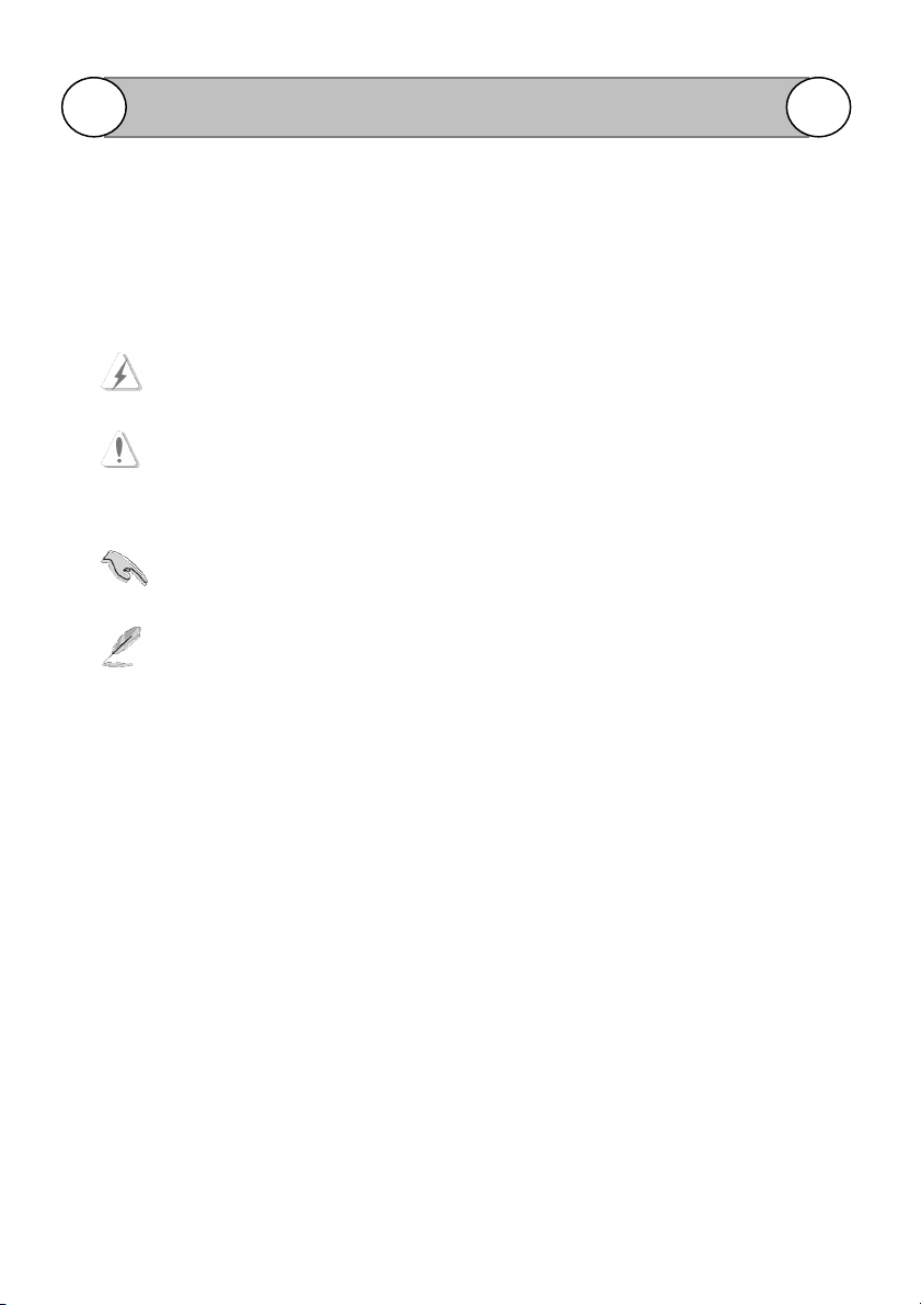
Conventions used in this guide
To make sure that you perform certain tasks properly, take note of the following symbols to use
throughout this manual.
WARNING: Information to prevent injury to yourself when trying to complete a task.
CAUTION: Information to prevent damage to the components when trying to complete
a task.
IMPORTANT: Information that you must follow to complete a task.
NOTE: Tips and additional information to aid in completing a task.
3
Page 4

Important Safeguards and Warning
Important Safeguards and Warning
It is not recommended to install this product by unqualified person.
The method and material of installation should be insured for the weight of the product
and enclosure as pan/tilt, camera lens, and so on
Stop using and power off the product if any unusual smell or smoke comes from the
camera.
Do not install the camera in an intermittent lighting environment.
Do not aim the camera at the sun or any other strong light source
Do not install the camera where it might be exposed to rain or water.
Do not drop the camera or examine it in severe shocks or vibrations.
Do not touch the front glass of the camera with a dirty or coarse stuff.
Do not install the product under humid conditions, near flammable or explosive gases.
4
Page 5

Product Introduction
Chapter 1 Product Introduction
It can control output decoders, integrated camera, speed dome, or integrated PT unit. It can also
be used in our DVR system.
1-1. Product Package Content
Please check the package content by the following list.
Joystick Keyboard (2D or 3D or 4 D) x 1 pcs
Phone Box x 1 pcs
DC 9V/1A Switching Power Adapter x 1 pcs
Flat Cable with RJ45 Jack x 1 pcs
User Manual x 1 pcs
1-2. Technical Parameters
1. Baud Rate: 1200 Bit/S, 2400 Bit/S, 4800Bit/S, or 9600Bit/S
2. Parameter: 8 Bits, 1, N, Stop
3. Communication: RS-485
3. Power supply: DC 9V/1A
4. Communication distance: Max 1200m
5. Control node: Max 64 speed domes.
6. Communication Protocol: Pelco “ P “ or “ D “ selectable
7. Operation temperature: -10℃-50℃
5
Page 6

1-3. Product Overview
FSKY-100 Connection Diagram
Function Description
1. Before power it, please check the cables, and make sure they are right connection.
2. Move the 2D, 3D or 4D joystick up/down/right/left to change the Speed dome pan or tilt
direction, the moving speed increases as the offset. Turning the knob on the 3D
joystick can control the camera TELE/WIDE and the 4D joystick provide a additional
affirm function when push the top (red color) button of joystick.
6
Page 7

A
D
B
C
Keypad and LCD panel Function Description
Function Description
Front Panel Back Panel
When you turn on the power the LCD
will show the information as below
Please refer to the function
description:
CAM: Display for camera ID address
INPUT: Display the status of current
operation
PROTOCOL: Show the current
control Speed dome protocol.
BAUD: Display the control baud rate.
A: Power input: Connect with DC9V
power supply.
B: RX OUT: Link to Phone Box for
Speed dome connection
C: RX IN: Reserve
D: MATRIX: Reserve
MON=001 CAM=001
INPUT: 000
PROTOCOL: PELCO-P
BAUD: 9600
1. LCD DISPLAY
This display will show the current ID number, protocol, baud rate and status.
2. 0~9 Number
Used for setting the camera ID, Preset number and modify the keyboard parameters.
7
Page 8

3. CAM
Select camera ID: Enter the Speed dome ID (0-255) by the number key then press CAM
key. i.e. Number + CAM . The number will be displayed after item CAM on the LCD.
For example: You want to select the ID 128 PTZ camera, press “ 1 “ + “ 2 “ + “ 8 “ and
“ CAM “ key at a time. The LCD will show CAM=128, repeat the same process to select
and other ID.
4. MON Reverse.
5. CLOSE/OPEN, NEAR/FAR, and TELE/WIDE
This is used when controlling the actions of the IRIS, FOCUS, and ZOOM of the zoom lens
connected to the speed dome or PT camera which with Pelco Protocol.
Under Manual mode, pressing key CLOSE and OPEN can control the IRIS function.
Function Description
Under Manual mode, pressing key NEAR and FAR can control the
Under Manual mode, pressing key TELE and WIDE can control the Zoom function
6. MENU
Press key MENU it gets turned on, and the OSD of Speed dome will be enable. Exit the
menu (OSD) from the exit item of the camera OSD (recommended) or press key MENU
again; it gets turned off for next call.
Press OPEN key to enter the next menu setting.
Turn the menu by pressing WIDE and TELE, adjust the parameter value by pressing FAR,
and exit the adjusting by pressing NEAR.
7. TOUR
For FDPI-27X/35X/36X, FDMO-27X/35X/36X, PTZWO-220 and SDCI-220 model:
Press key Tour, the LED will be light and star to tour the multi preset position.
Press key Tour again, the LED will be off and stop to tour the multi preset position.
For SDCI-220, PTWO-100 and PTCI-100 model:
Press key 51 + PRESET star to tour the multi preset position. Move the Joystick to stop
tour function.
8
Focus function.
.
Page 9

Function Description
8. SCAN. (360
For FDPI-27X/35X/36X, FDPI-220, FDMO-27X/35X/36X, PTZWO-220 and SDCI-220
model:
Press key SCAN. The LED gets turned on, and 2 points auto scan begins.
Press key SCAN again. The LED gets turned off, and auto scan stop.
For SDCI-220, FTWO-100 and FTCI-100 model:
Press key 53 + CALL, star to Auto Scan function.
Move the Joystick to stop Auto Scan function.
9. SHIFT
Press key SHIFT, it gets turned on, and SHIFT is in effect. Press key SHIFT again, it gets
turned off, and SHIFT is off no effect.
10. PATTERN
Press key PATTERN, the LED will be light and star to Group tour function.
Click SHIFT + PATTERN + Number to enable the Group tour scan function. For example:
If you want to have the Group 4 tour scan; click SHIFT + PATTERN + 4
Press key PATTERN again, the LED will be off and stop to Group tour function.
11. BEFORE
°°°°
pan auto scan or 3 D Scanner)
Move the Speed dome move to previous preset location.
12. NEXT
Move the Speed dome move to next preset location.
13. CALL
Move to preset location: This is function for search or move the preset position of the speed
dome or receiver. Entry the Preset number and then press CALL key to move the speed to
this Preset location. i.e. Number + CALL the Speed dome will move this preset location. If
succeed, the number input area will reset automatically (i.e. CAM - 000).
9
Page 10

14. ENTER
Press key ENTER, the Number input and setting area will be confirmed.
15. CLEAR
Press key CLEAR, the Number input area will reset
16. PRESET
Set up the Presets: Move the joystick, to adjust Pan/Tilt/Zoom of camera to select the
surveillance position. Input number and then press [PRESET] key. i.e. N + PRESET
Clear the presets: Input the preset number, and press [SHIFT] + [CLEAR] key.
i.e. Number + SHIFT + CLEAR key.
17. MUX-C: Revere
18. AUX1: Press key AUX1, turn on the fan and push AUX1 key again to turn off fan.
19. AUX2: Press key AUX2 to turn on the heater and push AUX2 key again to turn off heater.
20. AUX3: Press key AUX3, star to turn on the heater and fan at a time. Push AUX3 Key again
to turn off the heat and fan.
21. AUX4: Press key AUX4 to turn on/off the relay of Speed dome, such as wiper.
Function Description
22. PGM
Input 2+4 key, and then press key PGM to select Baud Rate to 2400.
Input 4+8 key, and then press key PGM to select Baud Rate to 4800.
Input 9+6 key, and then press key PGM to select Baud Rate to 9600.
Input 1+9+2 key, and then press key PGM to select Baud Rate to19200.
Input 4+4,and then press key PGM to select Pelco D protocol.
Input 5+0,and then press key PGM to select Pelco P protocol.
10
Page 11

BAUD
RATE
9600
Function Description
1-4. Setup the Keyboard parameters
Please follow the steps below to setup keyboard parameters.
Step 1. Press the [SHIFT] + [MENU] key and below picture will be shown.
Step 2. Enter the 4 numbers password and below picture will be shown. The default is 0000.
PASSWORD:
>MODE: 3D
SET UP1
Step 3: Move joystick up or down to select parameter, which you want to modify. The selected
item will show a “> “ mark.
Step 4: Click “ ENTER “ key to modify the parameter. Move the up or down of joystick to choice
the parameter.
Step 5: Click “ ENTER “ to confirm the setting. The cursor will move to move the main menu for
another setting.
Step6: Click “ PGM “ key to save and exit the parameters setting.
PROTOCOL: PELCO-P
:
11
Page 12

BAUD
RATE
9600
PASSW
ORD ENABLE: Y
Function Description
1-5. The function description of Keyboard parameters
MODE: You can select the joystick type. 2D/3D/4D: for 2D/3D/4D joystick operation.
PROTOCOL: The FSKY-100 keyboard provides Pelco P and D for selection.
INITIAL SET: Enable the default setting.
The default setting is off.
PASSWORD: Provide 4 umbers Password to protect the parameters setting. The default is 0000.
PASSWORD ENABLE: Enable (Y) the password protection and you need to enter the password
when you entry the parameters setting of Keyboard. The default setting is off.
BAUD RATE: Provide 2400, 4800, 9600, 19200 Baud rate.
S/N: Display the series number for each joystick device.
>MODE: 3D
PROTOCOL: PELCO-P
SET UP1
:
SET UP2
>INITIAL SET: OFF
PASSWORD: ****
SET UP3
>S/N: WB410800101001
12
Page 13

Function Description
1-5 Inner connection diagram
B
/
L
O
/
R
B
/
K
R
/
D
S
/
L
B
/
R
Y
/
L
G
/
R
Connect O/R with RS-485+ A (Y) Connect S/L with RS-485- B (Z)
There is a diagram on the box, please take it off before using.
13
 Loading...