

Page 1
1
Packaging Contents
Please check the contents of your new Network IP Camera when you unpack the package. If any
item is missing, please contact your dealer of purchase for help. The package includes the
following items:
Network IP Camera x 1ea
Bundle NVR & CMS software CD x 1ea
Quick User manual x 1ea
Accessory package x 1 set.
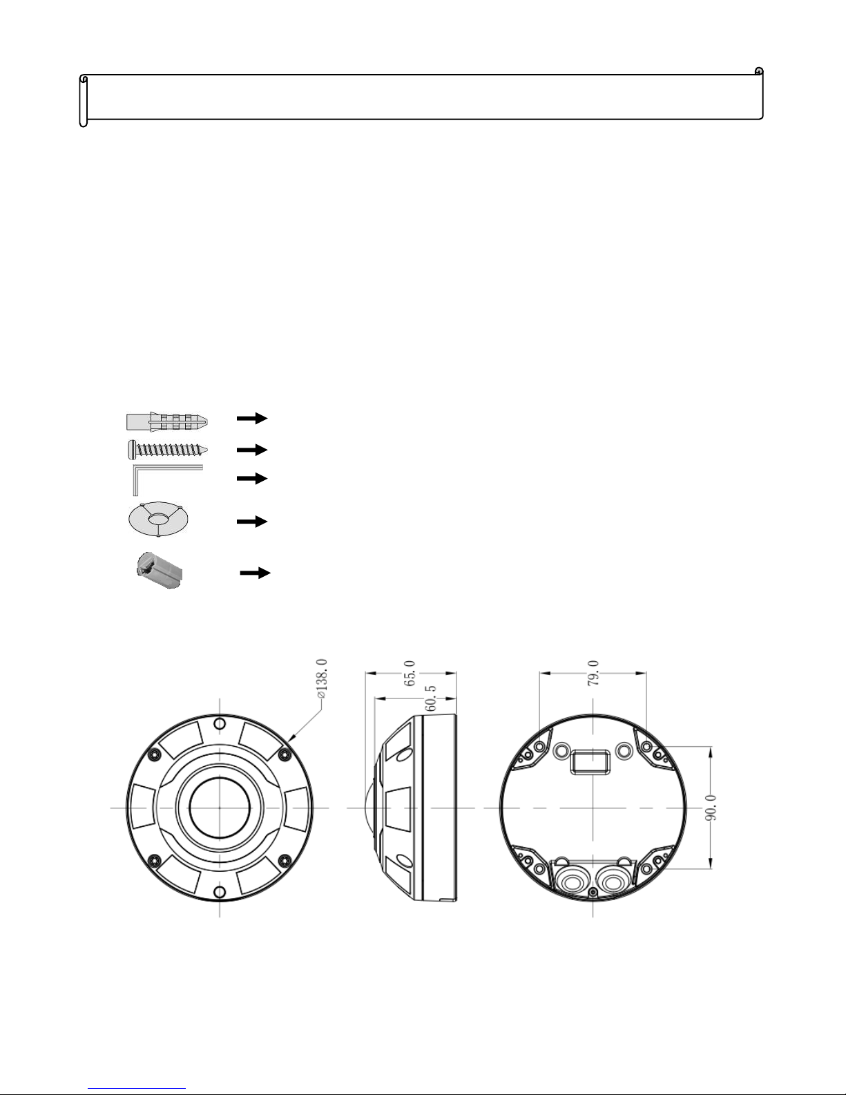
Product Dimension
FE-5MIPN06-F01 IR Fisheye Network Camera Quick Menu
v
1.1
RJ-45 Female- Female Converter * 1ea
Anchor 7x27 * 4 ea
Screw 4 x27 Tp1 Bnd Sus *4 ea
Hexagon wrench 3.0mm L type * 1 ea
Mount hole sticker * 1ea
Page 2
2
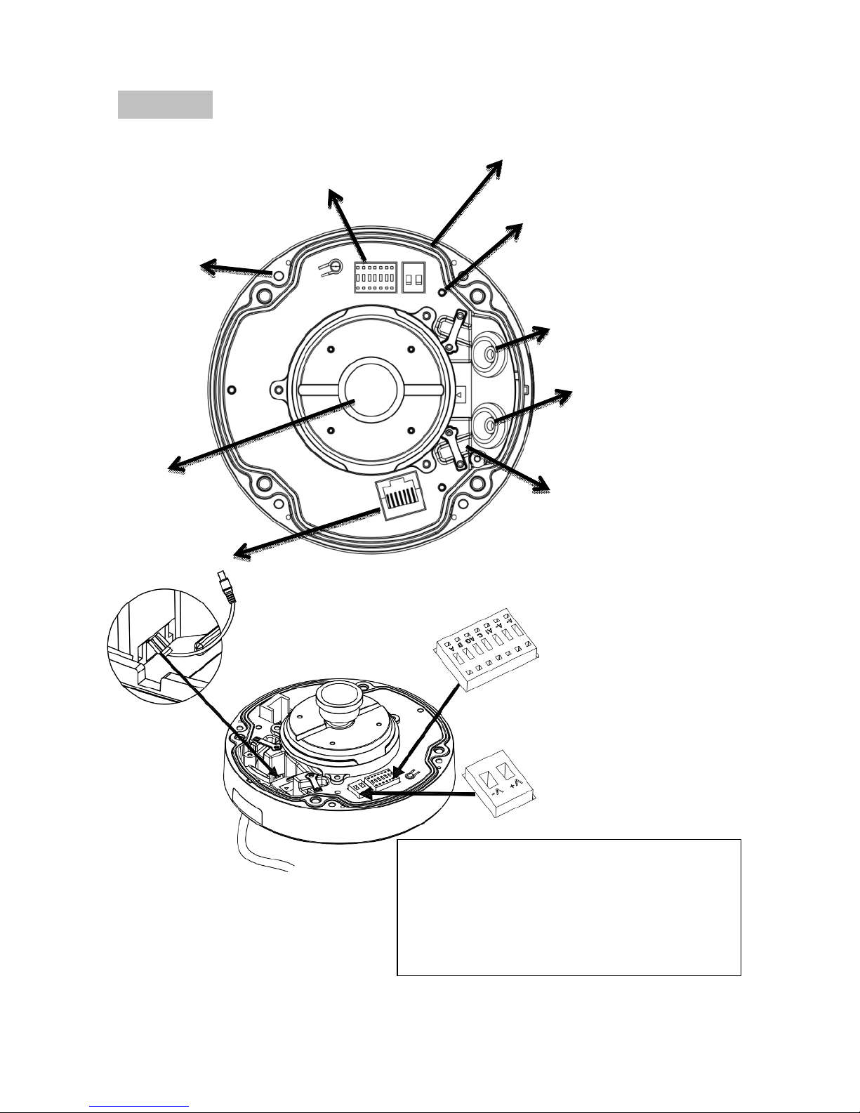
Product Parts Description
Inner View
Rubber Seal plug on
the hole for RJ45
Ethernet Cables
Alarm I/O & Audio in/out port
Power block
Lens
RJ45 Socket
Rubber Seal plug on the
hole for Power & I/O &
Audio in/out Cables
Reset Button
Fix hole
Cabling Cutout &
fixed bracket
A+: Alarm out A-: Alarm out
AI: Alarm in C: Alarm in
A/B: Audio in/out AG: Audio ground
V+: DC12V(+)
V -:
DC12V(+)
Page 3
3
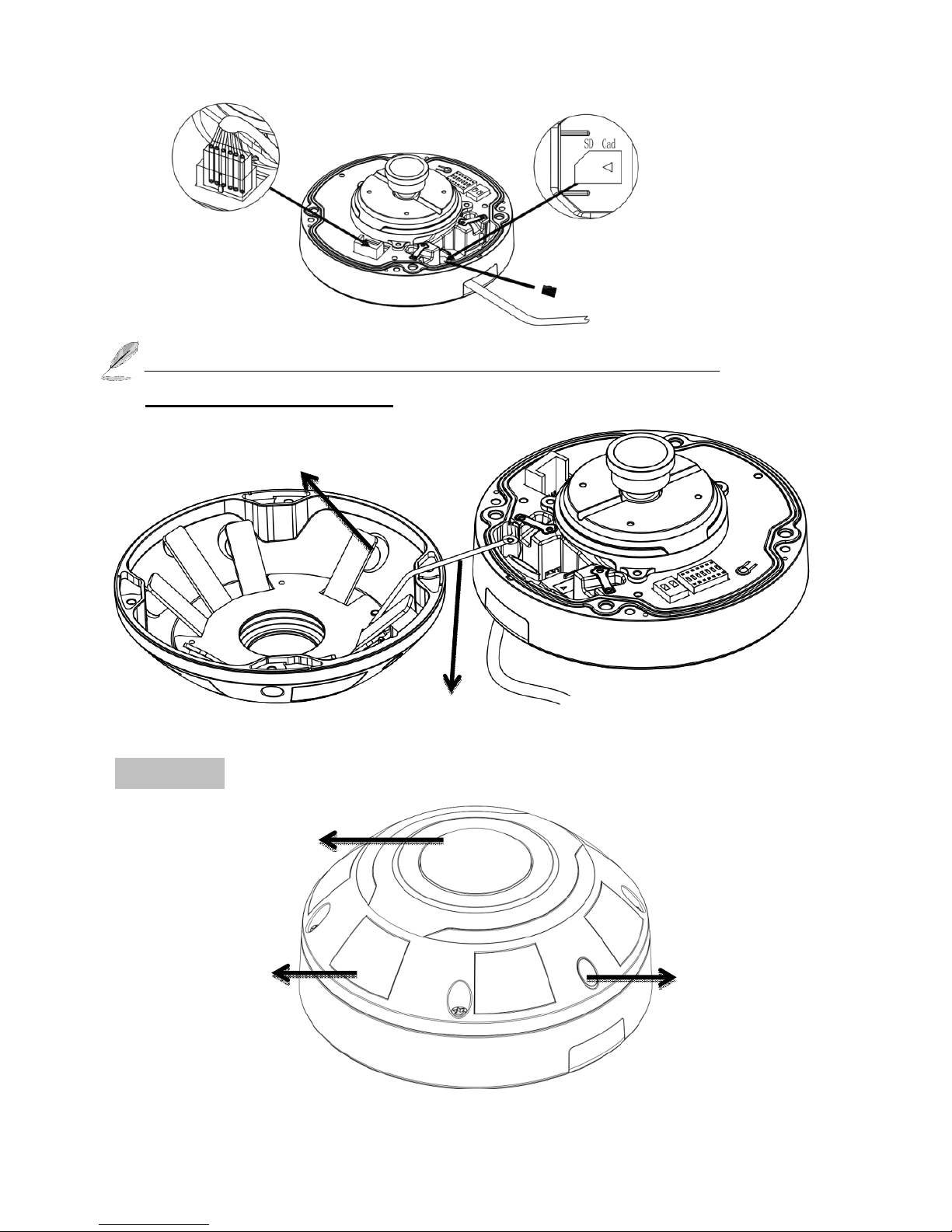
The SD Card, TV out and alarm in/out are optional function (For
FE-5MIPN06-F01-F only).
Outer View (IK10-rated Vandal-proof Dome Housing)
Micro SD card slot
Safety cable
IR LED
Lens
IR
sensor
IR lights hidden
beneath panel
Page 4

4
Hardware Installation
1. Opening Dome Cover
First, use the supplied
screwdriver to loosen the four
screws and detach the dome
cover from the camera base.
Then, follow the steps below
to install the camera to either
a ceiling or a wall.
2. Connect & assembly RJ45 Ethernet Cable
a. Drill a hole on the rubber seal
plug and insert an UTP cable
through the opening.
b. Strip part of the sheath from the
UTP cable.
c. You will need an RJ45 crimping
tool to attach the Ethernet wires
to a connector. When done,
connect the cable to the
camera’s Ethernet RJ45 socket.
d. Feed the Ethernet cable from
the bottom of the camera and
through the hole. Attach the
rubber seal plug for water proofing and then fix cable with the fixed bracket.
3. Connecting DC Power Cable
a. Add the supplied rubber washer to the cable as shown in the picture.
b. Feed the cable from the bottom of the camera and fix the cable with the bracket.
2
Connect the DC supplied power & alarm I/O& Audio in/out cables.
Page 5

5
4. Ceiling/Wall Mount installation
a. Attach the supplied alignment sticker for camera base to the ceiling/wall, using the
three circles on the sticker, drill three pilot holes into the ceiling. Then hammer the
four supplied plastic anchors into the holes and then secure the camera base to the
ceiling/wall with four supplied screws.
b. Drill a cable hole on the ceiling/wall, and feed the cables through the hole, then
connect the Ethernet cable and the I/O cable to the socket.
c. Attach the dome cover into the camera base.
d. Secure the four screws with the supplied star driver. Make sure all camera parts are
securely installed.
Page 6

6
Network Deployment
General Connection (without PoE)
1. Connect RJ45 Ethernet cable to a switch. Use a Category 5 Cross Cable when your network
camera is directly connected to PC.
2. Connect the power cable from the Network Camera to a power outlet.
Power over Ethernet (PoE)
The Network Camera is PoE-compliant, allowing transmission of power and data via a single
Ethernet cable. Follow the above illustration to connect the Network Camera to a PoE-enabled switch
via Ethernet cable.
Assigning an IP Address
You must know the IP address of
IP Camera before you can
connect to it. The IP Camera
will use DHCP server on your
local network to obtain an IP
address automatically by default.
So, you can check your DHCP
server’s IP address lease table to
find the IP address of IP Camera
Page 7

7
or also can use the utility program ‘IPSerch.exe’ to find the IP address of IP Camera, which comes
with the CD-ROM. Please follow up the processes as below to find out the IP address of IP camera
by “IPSearch utility”.
Step 1. The “IPSearch.exe “program will search for I-View’s IP cameras on the same LAN.
Double click this program show the window as below.
Step 2. Press “Search “button to search for all IP Cameras on your local network.
Step 3. If you need to change IP address on the selected IP Camera, change the IP address and
Gateway IP, then click the “OK” button to save the setting.
Step 4. If you no longer need to use this utility, click “Exit” button to close it.
Step 5. Select the device which list on the left section of diagram.
1. The default User name / Password is “admin / 123456 “ and IP address is 192.168.0.123.
2. Push the “Reset button” become to default setting when IP camera cannot connection.
3. Make sure all IP Cameras are powered on and connect to local network first.
4. The RTSP Streaming command code: Main streaming: rtsp://IP Address:Port/media/live/1/1
Sub streaming: rtsp://IP Address:Port/media/live/1/2
Run the IP camera from I.E. Browser
OS: Microsoft Windows 2000/XP/Vista/7/8/10 and Browser: I.E.7 or above.
Install ActiveX Plug-in on I.E. Browser
You can connect to the IP camera by Internet
Explorer or other web browsers for remote
viewing by entering IP address in address bar.
When you connect to IP Camera, the use login
screen will appear when you get connected.
Please entry the user name / password to login.
The default User name / Password is
“admin / 123456 “ and IP address is
192.168.0.123
If you connect to IP Camera first time, you’ll see the following message; this message prompts you
that you need to install ActiveX plug-in before you can see the video from IP Camera.
Page 8

8
IE 8 and earlier version:
Right click the indication bar and click: “Install This Add-on for All Users on This Computer…” to
install ActiveX plug-in.
IE 9 version:
Click ‘Install’ button located at the bottom of I.E. to install ActiveX plug-in. If you’re prompted that
the Windows Firewall has blocked some features of this program. Click “Allow access” button to
enable the IP Camera function properly. When you’re installing Internet Explorer plug-in, you may
also be prompted the diagram. Please click “Yes” to allow changes.
IE 10 version:
Click ‘Install’ button located at the bottom of I.E. to install ActiveX plug-in, the process as below:
Click “Internet options” section, then choice “ Security “ tab >> “ Trusted sites “ and change the
bar to “Low”. Click “ Sites “ to add the trusted site for this IP camera. Please refer to the diagram.
 Loading...