

Page 1
Version: V1.0.
Doc. No: 2014021601
Page 2

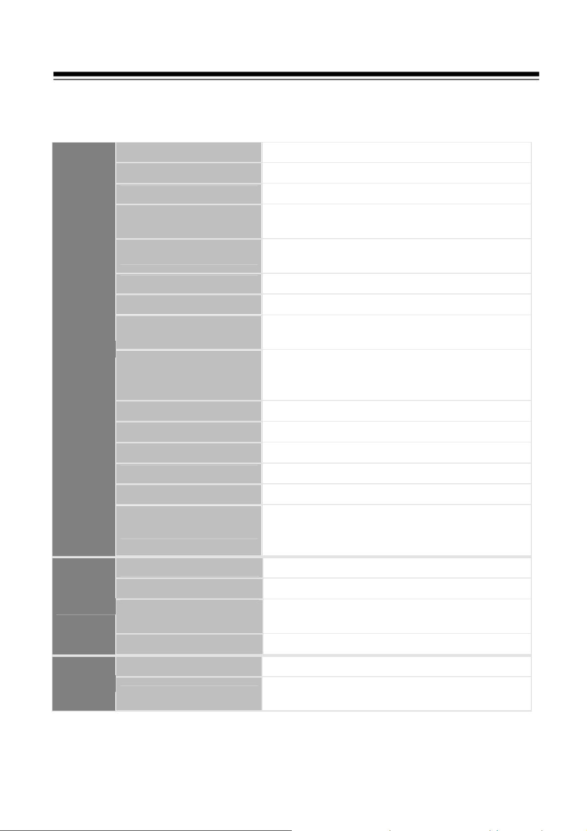
Table of Contents
0. Safety Information …………………………………………………....2
1. Features ……………………………………………………………….7
1.1
Main Features …………………………………………………7
1.2
Integrated Super Speed PTZ Rotator ……………………… 8
1.3
Built-in High Definition Day/Night Camera………………… 8
1.4
All-weather Outdoor Design ………………………………… 8
1.5
Function Instructions …………………………………………8
2. Technical Specification……………………………………………..9
2-1. Specification…………………………………………………… 15
2-2. Packaging Contents…………………………………………… 15
2-3. Product Dimension…………………………………………… 15
2-4. Cable Description………………………………… ………… 16
3. Installation Guide……………………………………………………12
3-1. Installation Method…………………………………………… 17
3-2. Installation Procedures…………………………………………18
3-3. Network Deployment……………………………………………20
4. Running IP Camera by Witness Pro NVR software…………..…21
4-1. Install Witness Pro NVR software……………………………21
4-2. Setting IP camera for Witness Pro NVR software……………22
5. Running IP Camera by I.E. Browser……………………………....25
5-1. Install ActiveX Plug-in on I.E. Browser……………………… 26
5-1. The Function Description of Live Window…………………29
5-2. Operation Instructions………………………………………33
5-3. The Network setup Function Description………………… 35
6. OSD Menu Function Features……………………………………….56
7. Troubleshooting …… ………………………………………………..89
1
Page 3
Safety information
This symbol indicates that dangerous voltage consisting a risk of electric
shock is present within this unit.
This exclamation point symbol is intended to alert the user to the presence
of important operating and maintenance (servicing) instructions in the
literature accompanying the appliance.
WARNING
To prevent damage that may result in fire or electric shock hazard, do not
expose this appliance to rain or moisture.
To prevent injury, this apparatus must be securely attached to the floor /
wall in accordance with the installation instructions.
WARNING
1. Be sure to use only the standard adapter that is specified in the
specification sheet using any other adapter could cause fire, electric shock,
or damage to the product.
2. Incorrectly connecting the power supply or replacing battery may cause
explosion, fire, electric shock, or damage to the product.
3. Do not connect multiple cameras to a single adapter. Exceeding the
capacity may cause the abnormal heat generation or fire.
4. Securely plug the power cord into the power receptacle, insecure
connection may cause fire.
5. When installing the camera, fasten it securely and firmly. The fall of
camera may cause personal injury.
2
Page 4

6. Do not place conductive objects (e.g. screwdrivers, coins, metal parts, etc.)
or containers filled with water on top of the camera. Doing so may cause
personal injury due to fire, electric shock, or falling objects.
7. If any unusual smells or smoke come from the unit, stop using the product.
In such case, immediately disconnect the power source and contact the
service center. Continued use in such a condition may cause fire or
electric shock.
8. If this product fails to operate normally, contact the nearest service center
and never disassemble or modify this product in any way. (I-View is not
liable for problems caused by unauthorized modifications or attempted
repair.)
9. When cleaning, do not spray water directly onto parts of the product.
Doing so may cause fire or electric shock.
CAUTION
1. Do not drop objects on the product or apply strong shock to it. Keep away
from a location subject to excessive vibration or magnetic interference.
2. Do not install in a location subject to high temperature (over 50°C), low
temperature (below -10°C), or high humidity. Doing so may cause fire or
electric shock.
3. If you want to relocate the already installed product, be sure to turn off the
power and then move or reinstall it.
4. Remove the power plug from the outlet when then there is a lightning.
Neglecting to do so may cause fire or damage to the product.
5. Keep out of direct sunlight and heat radiation sources. It may cause fire.
6. Install it in a place with good ventilation.
7. Avoid aiming the camera directly towards extremely bright objects such as
sun, as this may damage the CCD image sensor.
8. Apparatus shall not be exposed to dripping or splashing and no objects
filled with liquids, such as vases, shall be placed on the apparatus.
9. The Mains plug is used as a disconnect device and shall stay readily
operable at any time.
10. Do not expose the camera to radioactivity. Radioactivity exposure may
damage the CCD.
3
Page 5

IMPORTANT SAFETY INSTRUCTIONS
Read these instructions.
Keep these instructions.
Heed all warnings.
Follow all instructions.
Do not use this apparatus near water.
Clean only with dry cloth.
Do not block any ventilation openings. Install in accordance with the
manufacturer’s instructions.
Do not install near any heat sources such as radiators, heat registers, or
other apparatus (Including amplifiers) that produce heat.
Do not defeat the safety purpose of the polarized or grounding-type plug.
A polarized plug has two blades with one wider than the other. A
grounding type plug has two blades and a third grounding prong. The wide
blade or the third prong is provided for your safety. If the provided plug
does not fit into your outlet, consult an electrician for replacement of the
obsolete outlet.
Protect the power cord from being walked on or pinched
particularly at plugs, convenience receptacles, and the point
where they exit from the apparatus.
Only use attachments/accessories specified by the manufacturer.
Use only with cart, stand, tripod, bracket, or table specified by the
manufacturer, or sold with the apparatus.
Unplug this apparatus when a card is used. Use caution when moving the
cart/ apparatus combination to avoid injury from tip-over.
Refer all servicing to qualified service personnel. Servicing is required
when the apparatus has been damaged in any way, such as power supply
cord or plug is damaged, liquid has been spilled or objects have fallen into
the apparatus, the apparatus has been exposed to rain or moisture, does not
operate normally, or has been dropped.
Apparatus shall not be exposed to dripping or splashing and no objects filled
with liquids, such as vases, shall be placed on the apparatus.
4
Page 6
uipment has been tested and found to comply with the limits for a Class A
digital device, pursuant to part 15 of FCC Rules. These limits are designed to provide
protection against harmful interference when the equipment is operated in a
This equipment generates, uses, and can radiate radio frequency energy and, if not
installed and used in accordance with the instruction manual, may cause harmful
ential area
is likely to cause harmful interference in which case the user will be required to correct
SAFETY INFORMATION
FCC STATEMENT
This device complies with part 15 of the FCC Rules. Operation is subject to
the following conditions:
This device may not cause harmful interference, and
This device must accept any interference received including interference that
may cause undesired operation.
CAUTION
This eq
reasonable
commercial environment.
interference to radio communications. Operation of this equipment in a resid
the interference at his own expense.
Correct Disposal of This Product (Waste Electrical & Electronic Equipment)
This marking on the product, accessories or literature indicates that the
product and its electronic accessories should not be disposed of with other
household waste at the end of their working life. To prevent possible harm
to the environment or human health from uncontrolled waste disposal,
please separate these items from other types of waste and recycle them
responsibly to promote the sustainable reuse of material resources.
Household users should contact either the retailer where they purchased this
product, or their local government office, for details of where and how they can
take these items for environmentally safe recycling.
Business users should contact their supplier and check the terms and conditions of
the purchase contract. This product and its electronic accessories should not be
mixed with other commercial wastes for disposal.
5
Page 7

About This Guide
Conventions used in this guide
To make sure that you perform certain tasks properly, take note of the following
symbols to use throughout this manual.
WARNING: Information to prevent injury to yourself when trying to
complete a task.
CAUTION: Information to prevent damage to the components when trying
to complete a task.
IMPORTANT: Information that you must follow to complete a task.
NOTE: Tips and additional information to aid in completing a task.
Trademark
I-View, FastCam III, @-Witness Pro, FreeView Pro, AnyCam, AnyNet and
MobileView are registered trademarks of I-View Communication Inc.
Microsoft, Windows Windows2000, XP, Vista, 7 and 8 are registered trademarks
of Microsoft Corporation. All other trademarks are the property of their
respective holders.
Customer Support
If technical problems arise with the use of our products in which you and your
vendor cannot resolve, please try the following: If you have an Internet
connection, visit the I-View website http://www.i-view.com.tw (Taiwan) for any
software or product updates, or email to support@i-view.com.tw (Taiwan) or Tel:
886-3-510-3001 Fax: 886-3-510-3002 (Taiwan). We are dedicated to
providing the highest quality support. E-mailing our tech support will give you
the chance to document each of the above items in a very clear and concise
manner and will give our support team a chance to document any problems and
respond with thoroughly researched answers.
6
Page 8

1. Features
1.1
Main Features
1080p HD SONY Exmor CMOS Sensor.
30 fps @ 1080p Full HD.
20x Optical Zoom Lens and 12x Digital zoom; total 240x zoom.
WDR for unparalleled visibility in high contrast environments.
Built-in Micro SD Card Slot for On-board Storage.
Support H.264 main/Low/Base line profile, and MJPEG Compression.
ROI (Region of Interest) encoding enhances the quality of specified image.
Ultra Low Compress Rate(ULCR) technology: LESS storage space, SAME
video quality.
Step less speed changes, auto zoom/speed matching.
Pan 0.01~360o/S, Tilt 0.01o~120o/S, Preset: 400o/S.
Pan 0.5o~20o, Tilt 0.5o~20o, Preset: 20o/s.
Timing actions for 7 days of programmable schedule.
Built-in Semi-conductor heater & digital temperature sensor.
PWM cooling fan vari-speed temperature control.
Reserved network interface and space for network module.
Pan Tilt accuracy +/- 0.1o, 220preset positions.
8 cruising tracks, each cruising track has 32 presets.
4 pattern tours, 10 Minutes memory, 500 programmable instructions.
8 auto scan with use-defined left and right boundaries and settable scan speed.
8 Privacy Zones with defined English camera title.
Auto Compatible PELCO_P, PELCO_D compatible.
The alarm can trigger preset, auto scan, cruising and pattern tours functions.
Set up the dome address via firmware without change the Dip switch.
Support wiper for clean the rain and dust. (Option).
Support Intelligent Auto Tracking (Option).
Built-in 802.3at Compliant PoE Plus (Option).
7
Page 9

1.2 Integrated Super Speed PTZ Rotator
Delicate stepping motor, stable, sensitive and accurate
360° Pan and 90° Tilt range (auto-flip) without blind area
Step less speed change, auto zoom/speed matching
Near / far IR Light auto matches camera zoom in/out
1.3 Built-in High Definition Day/Night Camera
Auto iris, auto back light compensation
Auto/manual white balance
Auto/manual brightness control
Auto/manual focus
Multiple compatible camera brands including Sony, Samsung, LG, CNB…etc.
1.4 All-weather Outdoor Design
6 Inch High die-cast alloy aluminum construction
High Precision Mould with high heat conductivity
Fully enclosed isolation design for heat sink
Nanometer Dustproof, waterproof and fog-proof lens\
IP66 Waterproof
3000V lightning and surge current protection
1.5 Function Instructions
Focus / PTZ Speed Auto Match
The pan/tilt rotation speed could be automatically adjusted according to the focus
in/out, which makes it much more practical for manual target tracking. (Only for
the auto tracking IR speed dome)
Auto Flip
In manual tracking mode, when a target object goes directly beneath the dome,
the video will automatically flips 180 degrees in horizontal direction to maintain
continuity of tracking. This function can also be realized by auto mirror image
depending on different camera models.
Preset Position Set up and Call Up
In the Preset function the dome stores the current pan/tilt angle, zoom and other
position parameters in its memory. When necessary the dome recalls these
parameters and adjusts the camera to a particular position. The user can store,
recall and clear the presets easily and promptly by using the keyboard controller.
8
Page 10

The dome can store up to 220 presets.
Auto Scan
Users can set up the left and right boundaries by control keyboard. Then speed
dome can scan between these boundaries. It supports up to 8 groups of scanning
paths.
Cruising Track
The preset position can be programmed to be recalled in a set of sequences. This
sequence can be set to let the camera scan from one position to the next in a cycle
at a set speed. This feature is called the “auto cruise”. The cruise sequence and
dwell time of each preset can be set. It supports up to 8 cruising tracks, each
cruising track with 32 presets.
Pattern Tour
Dome can memorize 600s running path or 500 programmable instructions. When
start pattern tour, speed dome will move automatically according recorded action
path. It supports 4 groups of pattern tours.
Guard Location
The dome will automatically return to preset position if there is no operation in a
period of vacant time.
Default Action
When you start up the dome camera or do not send commands over a long time,
the dome camera will return to its default functions which include the home place,
auto pan, auto cruise and pattern.
Dome Address Setup
The dome supports up to 256 addresses and the dome will only response to the
instructions given to its own address. Please check the dip switch on the bottom of
the dome for address setup.
Manual Object Tracking
The use can move the joystick up, down, left or right to track the appearing object
in the screen and use the joystick to zoom in and out with auto focus.
Privacy Mask Protection
Set black mask areas to protect the privacy zones. The black privacy locations can
be set, and support up to 8 mask zones. This function allows you to block or mask
certain area of a scene, for preventing the personal privacy from recording or live
viewing. A masked area will move with pan and tilt functions and automatically
adjust in size as the lens zooms telephoto and wide.
Timing Running Function
Users can set speed dome operation task at total 8 timing areas during 7 days.
9
Page 11

Coordinates and Directions Display
User can define the dome’s direction of due north, which will help to show
up the exact moving directions on screen. And zone title is supported to
display when the dome moves to the specified zone.
Auto Tracking
The dome will automatically fix and track the moving object according to the
user’s setup via OSD.
Motion Detection
The dome will detect the changes in the defined video zone and trigger alarm.
It supports to 8 video Locations, each with 4 detection zones.
Limit Stops
The dome can be programmed to move within the limit stops (left/right,
up/down).
Label Display
The on-screen label of the preset title, azimuth/elevation, zoom, time and dome
name can be displayed on the monitor. The displays of time and speed dome
name can be programmed.
3D Positioning
In the client software, use the left key of mouse to click on the desired position in
the video image and drag a rectangle area in the lower right direction, then the
dome system will move the position to the center and allow the rectangle area to
zoom in. Use the left key of mouse to drag a rectangle area in the upper left
direction to move the position to the center and allow the rectangle area to zoom
out.
Proportional Pan/Tilt
Proportional pan/tilt automatically reduces or increases the pan and tilt speeds
according to the amount of zoom. At telephoto zoom settings, the pan and tilt
speeds will be slower than at wide zoom settings. This keeps the image from
moving too fast on the live view image when there is a large amount of zoom.
Auto Focus
The auto focus enables the camera to focus automatically to maintain clear video
images.
Wide Dynamic Range (WDR)
The wide dynamic range (WDR) function helps the camera provide clear images
even under back light circumstances. When there are both very bright and very
dark areas simultaneously in the field of view, WDR balances the brightness level
of the whole image and provide clear images with details.
10
Page 12

Note: This feature varies depending on speed dome models.
Power On Memory
The dome supports the power on memory capability with the predefined resume
time. It allows the dome to resume its previous position after power is restored.
Scheduled Task
A time task is a preconfigured action that can be performed automatically at a
specific date and time. The programmable actions include: auto scan, patrol
1-8 ,pattern 1-4, preset 1-8,frame scan etc.
Park Action
This feature allows the dome to start a predefined action automatically after a
period of inactivity.
3D Digital Noise Reduction
Comparing with the general 2D digital noise reduction, the 3D digital noise
reduction function processes the noise between two frames besides processing the
noise in one frame. The noise will be much less and the video will be clearer.
PTZ and Lens Control
1) Zoom Control
Users can control zoom by keyboard to get near or far images.
2) Focus Control
The default setting is auto focus. The camera will auto focus based on the center
of the video display to get the clear image. In some special occasions, the user
could do the manual focus to get the desired image effect.
3) Auto Iris Control
Auto Iris is aiming to detect the environmental lights condition and adjust the iris
to get the stabilized brightness of the image.
4) Auto Back Light Compensation
In the highly bright background, auto back light compensation is aiming to
compensate the brightness of the dark object and adjust the background brightness
to get a clear image.
5) Auto/Manual White Balance
Auto/Manual WB adjust depending on the environment light changes.
6) OSD Setup
Call upon preset No.95 to enter into OSD menu setup interface. Press “Focus” to
choose menu items and press “Iris” to set menu contents.
11
Page 13
2. Technical Specifications
2.1 Specification
Camera
Image Sensor:
Effective Pixels:
Signal System:
Minimum
Illumination:
White Balance:
Gain Control:
S/N Ratio:
White Balance
Exposure Control:
WDR:
Shutter Time:
1/2.8’’ SONY Exmor™ CMOS sensor
1920(H)x1080(V)
PAL/NTSC
Less than 1.7 lx (F1.6, 50 IRE), 0.5 lx in
High Sensitivity Mode, 0 lux with IR ON
Auto/Manual/ATW/Indoor/Outdoor/Daylight
lamp/Sodium lamp
Auto/Manual/Max. (-3 to 28 dB, 2 dB steps)
≥ 50dB
Auto, ATW, Indoor, Outdoor Auto, Sodium
Vapor Lamp (fix/auto), One-push, Manual
AE Control: Auto, Manual, Priority (shutter
priority and iris priority), Bright, EV
Compensation, Slow AE
Auto/Manual
1/2 to 1/10,000 s, 21 steps
Lens
Pan/Tilt
Day& Night:
Digital Zoom:
Privacy Masking:
Focus Control:
Focal Length:
Angle of View:
Minimum Working
Distance:
Aperture Range:
Pan / Tilt Angle:
Pan/Tilt Speed:
ICR
12X
Spherical
Auto (Sensitivity: normal, low), One-push
AF, Manual, Infinity, Interval AF, Zoom
trigger AF
20x Optical Zoom, f=4.7 mm ~ 94.0 mm
54.1° (wide end) to 2.9° (tele end)
10-1500mm(Wide-Tele)
F1.6 to F3.5
360o continuous pan rotation/ 90o(Auto Flip)
Pan 0.01o~180o, Tilt 0.01o~100o (High
speed) /Pan:0.5o~35o/S, Tilt:0.5o~35o/S
12
Page 14

o
&
(Vair-speed)
360
Preset Speed
/S (high speed) / 35o/S (Vari-speed)
Presets
Number/Accuracy
Guard Location
Number of Preset:
Auto Scan
Auto Cruising
Pattern Tour
Park Action:
PTZ Position
Display:
Freeze Frame:
Smart-tracking:
220 / +/-0.1o
The dome will rotate back to preset position
after a period of vacant time.
256
8 auto scan tracks, user-defined left and right
boundaries and scan speed
8 cruising tracks, each cruising tracks has 32
preset positions, User-defined dwell time
4 groups, each one with 10 Minutes memory,
500 programmable instructions
Preset / Tour / Pattern / Scan
ON/OFF
Yes
Yes
Infrared
Alarm
Input
Output
Network
IR irradiation
distance:
IR irradiation angle:
Alarm Input:
Alarm Output:
Alarm Actions:
Composite Output:
Audio Input:
Audio Output:
Ethernet:
Image Resolution:
Frame Rate:
150m
Adjustable by zoom
1 Inputs
1 channel relay output, with configurable
alarm actions
Preset, patrol, pattern, SD/SDHC card
recording, relay output, notification on client
1.0Vp-p / 75Ω, composite, BNC
Line input: 4Vp-p; output impedance: 600Ω
Line level, impedance: 600Ω
10Base -T, /100Base-TX, RJ45 Connector
1920×1080
50Hz: 25 fps (1920×1080); 30fps (320x288)
13
Page 15
60Hz: 30 fps (1920×1080), 30 fps (320x240)
Client
GUI
Image Compression:
ROI encoding:
Audio Compression:
Protocols:
Simultaneous Users:
Micro SD Card:
User/Host Level:
Security Measures:
Camera Control:
Web Browser:
H.264 Baseline/Main/High profile; MJPEG
Support 5% areas of image
G.711ulaw/G.711alaw
IPv4/IPv6, HTTP, HTTPS, 802.1x, Qos,
FTP, SMTP, UPnP, SNMP, DNS, DDNS,
NTP, RTSP, RTP, TCP, UDP, IGMP, ICMP,
DHCP, PPPoE
Up to 8 users
SD/SDHC Slot, up to 64GB Edge recording
Up to 32 users,3 Levels: Administrator,
Operator and Media User
User authentication (ID and PW),
Host authentication (MAC address)
IP address filtering
Pan/Tilt, Zoom, Focus, Click centering,
Zoom by mouse dragging, Iris, preset calling
and programming, auto mode
IE 7+, Chrome (request Plug ),Safari,
support multi-language
General
Menu Language:
Protocols
Power Supply:
Operation:
Protection Level:
Mounting:
Dimensions:
Weight (approx.):
Mount Option:
English / Chinese
Auto Compatible PELCO_P, PELCO_D
12/5A VDC: 36W Max.
Temperature: -35o~ +60oC; Humidity:
0~90%
IP66 standard (outdoor dome)
TVS 4,000V lightning protection, surge
protection and voltage transient protection
Wall Mount/Ceiling mount optional
Φ220×304mm
5Kg
Long-arm wall mount, Corner mount, Pole
Mount, Power box mount
14
Page 16
2.2 Packaging Contents
Please check the contents of your new Network IP Speed dome Camera when
you unpack the package. The package includes the following items:
Network IP Speed Dome Camera x 1ea
Bundle NVR & CMS software CD x 1ea
User manual x 1ea
Switching Power Adapter. x 1ea
Wall Mount or Celling Mount. x 1ea
Safety Wire x 1pc
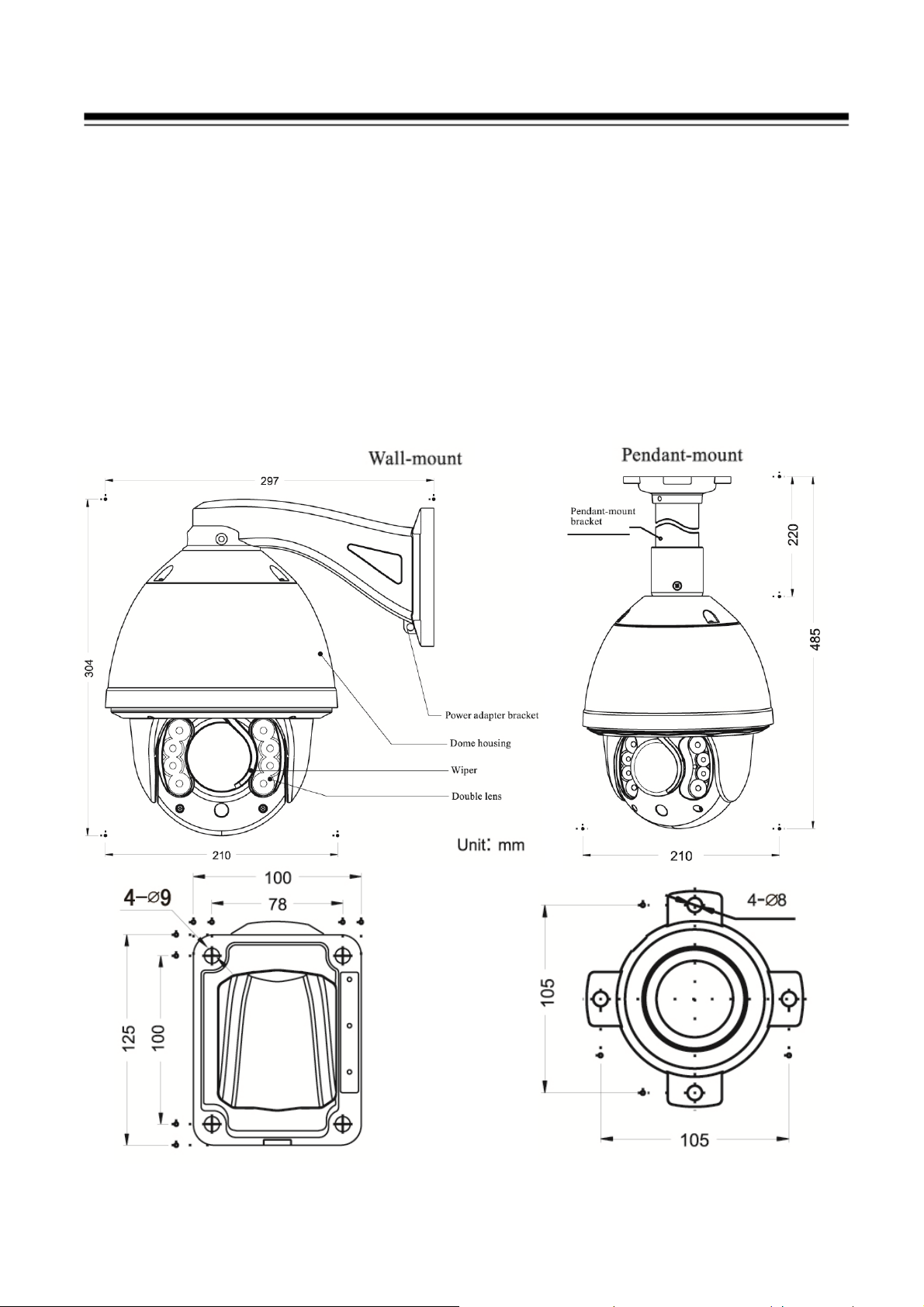
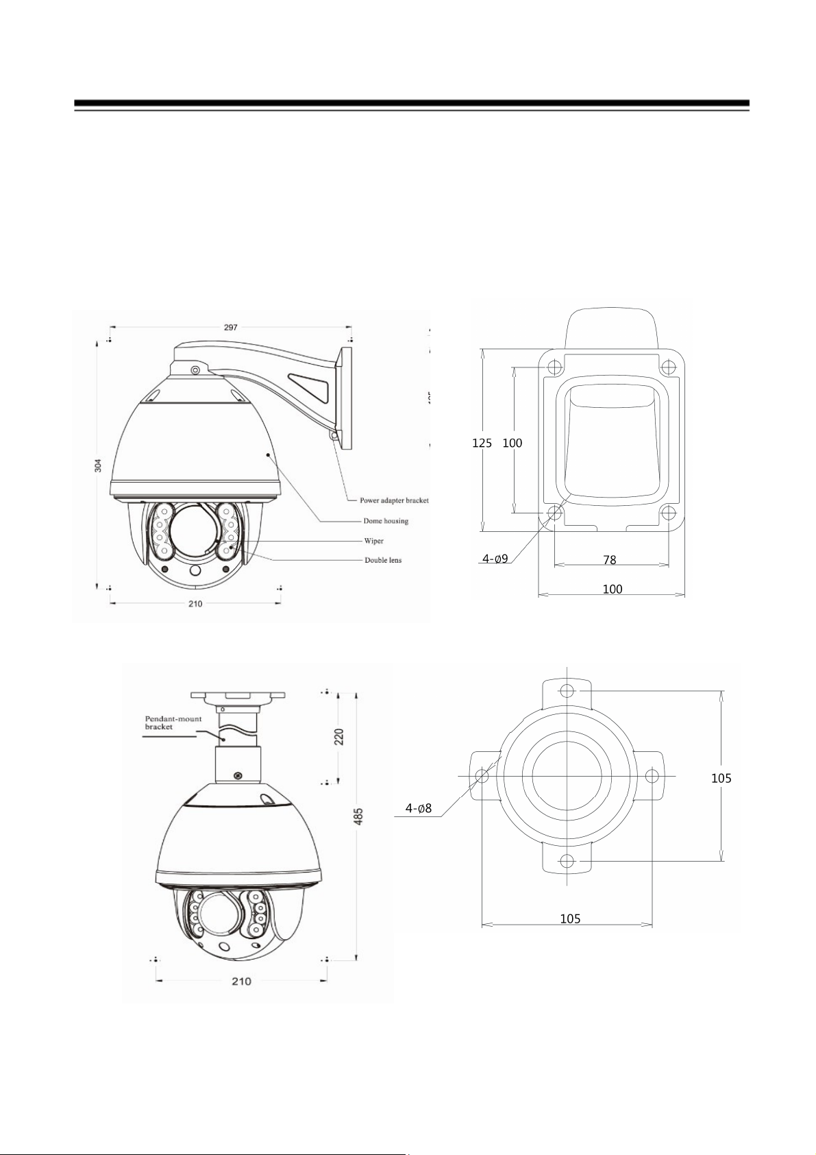
2.3 Product Dimension
15
Page 17
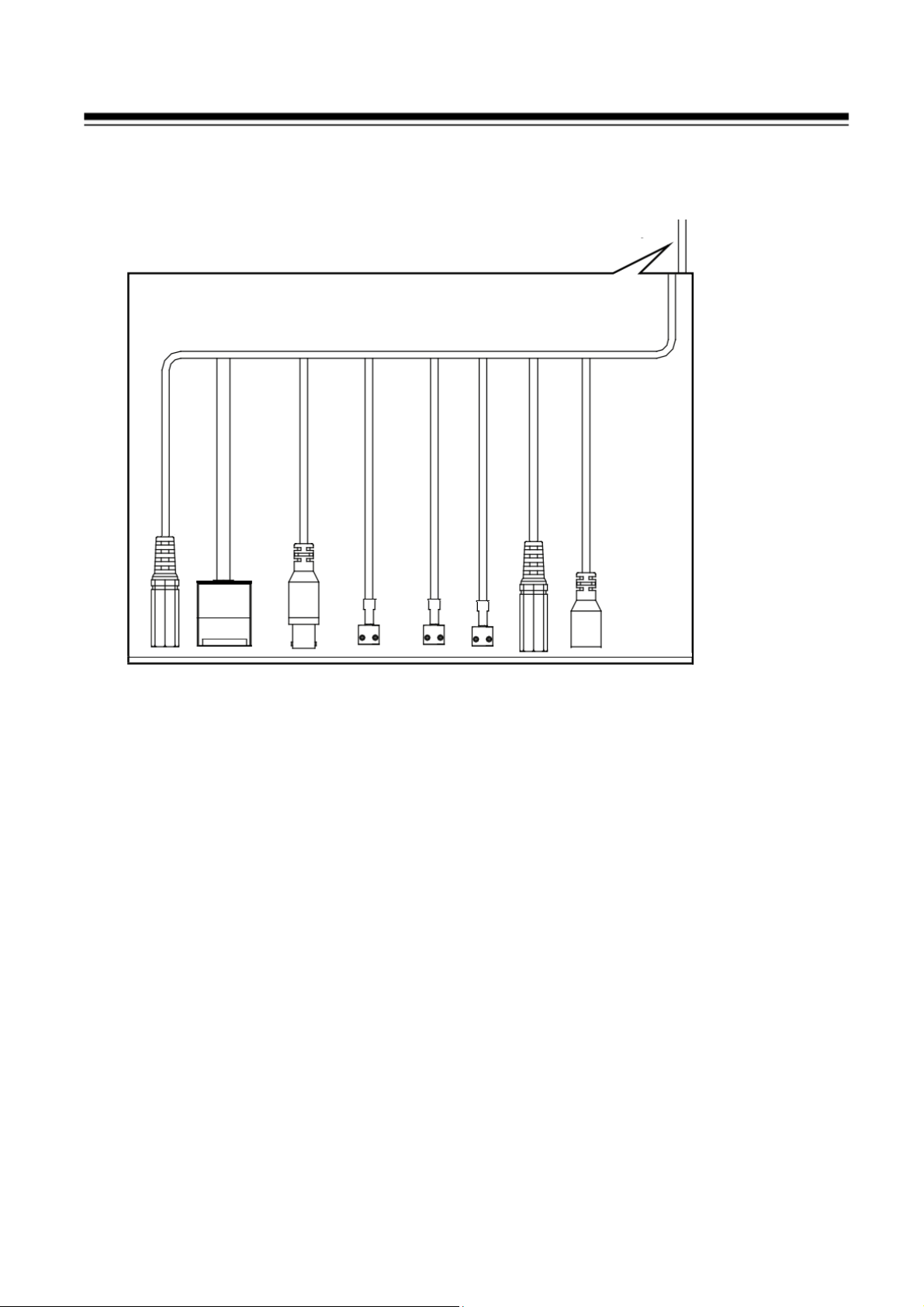
2.4 Cable Description
1) Network port: Plug the RJ-45 LAN cable. The Green LED on for power OK;
Green LED flash for communication; Yellow LED on for power OK.
2) Power cable: Connect the DC12V Switching power adapter.
3) BNC cable: Provide composite video signal for lens focus adjustment.
4) Audio in (Yellow): Plug in Microphone for audio input.
5) Audio output (Red): Plug Speaker (Request audio amplify) for audio output.
6) Alarm in#1: Connect to the sensor input (Dry contact).
7) Alarm in#2: Connect to the sensor input (Revised).
8) Alarm out: Connect to the trigger device such as light.
9) Rest cable: Turn on the power and push button , the parameters of IP camera
become to default setting.
16
Page 18
3. Installation Guide
3.1 Specification Installation Method
The IR speed dome could be installed in wall-mount and pedant-mount
Wall Mount
Pendant Mount
17
Page 19
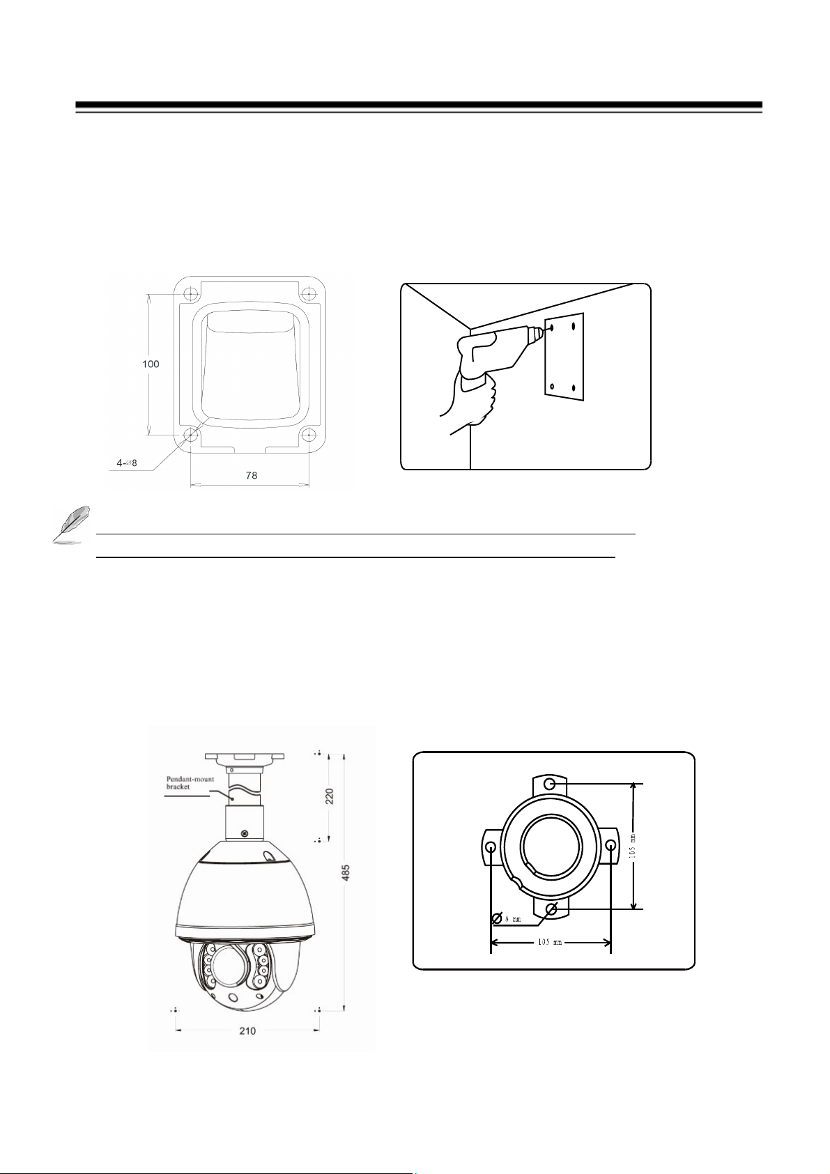
3.2 Installation Procedures
Wall-mount Installation Procedures:
1) Take out the bracket from the package (as shown), mark the installation hole
positions on the wall referencing to the bottom of bracket.
2) Drill the hole and install 4 pieces of M8 expansion bolt into the hole.
The wall and ceiling must be thick enough to install the expansion
bolts and can bear 4 times the weight of the dome camera itself.
3) Take out the IR speed dome and put the cables through the bracket.
Use M5 screws to fix the bracket and dome body.
4) Use 4 pieces of M8 screw nuts with washer to fix the bracket on the wall.
Pendant-mount Installation Procedures:
1) Take out the bracket from the package (as shown), mark the installation hole
positions on the ceiling referencing to the bottom of bracket.
18
Page 20
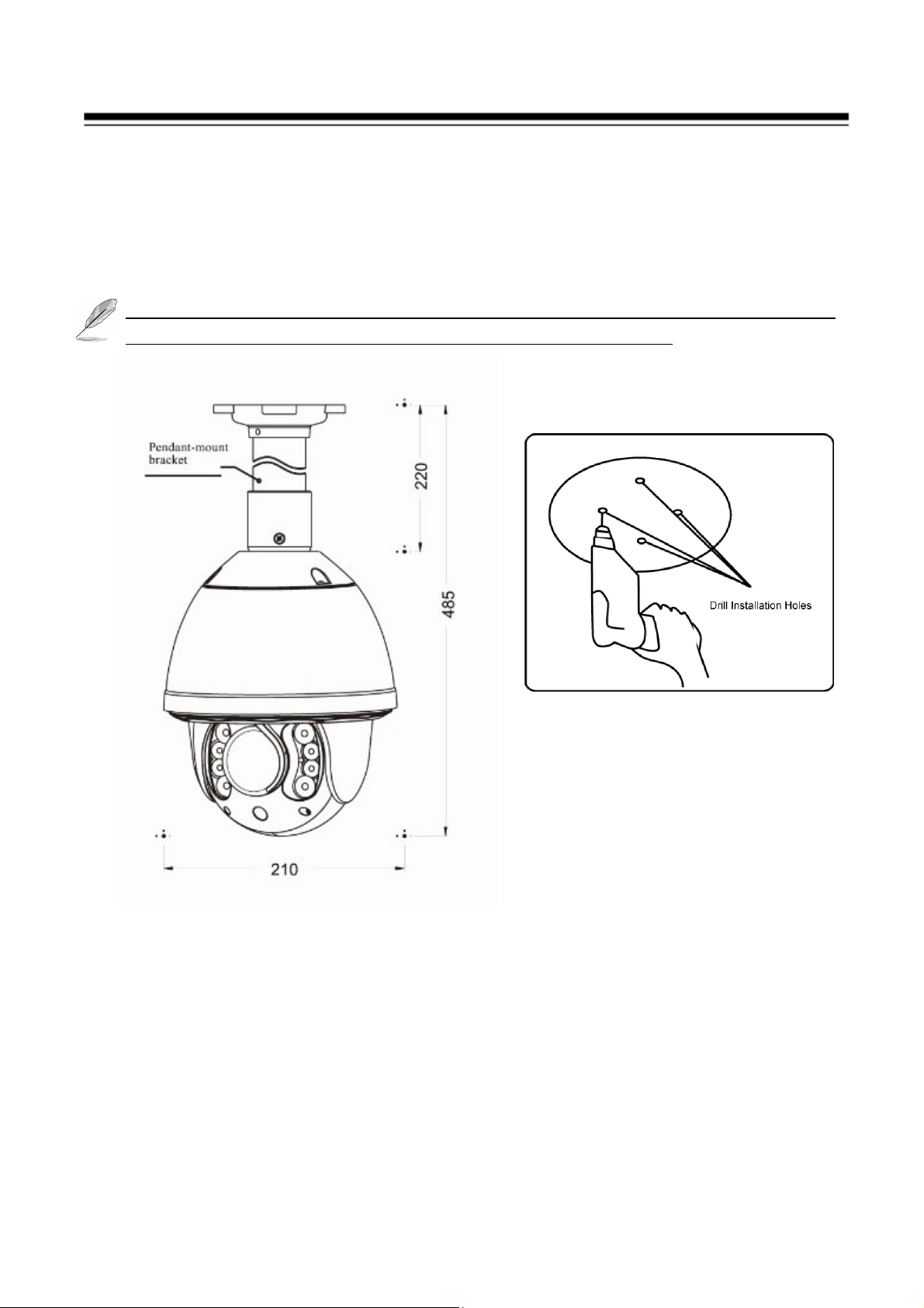
2) Drill the hole and install 4 pieces of M8 expansion bolt into the hole.
3) Take out the IR speed dome and put the cables through the sockets on the
bottom of the pendant bracket. Use M5 screws to fix the bracket and dome
body.
4) Use screw nuts with washer to fix the bracket on the wall.
Pendant-bracket is not designed for outdoor installation. If specially required,
please do make sure the waterproof installation of the dome.
19
Page 21
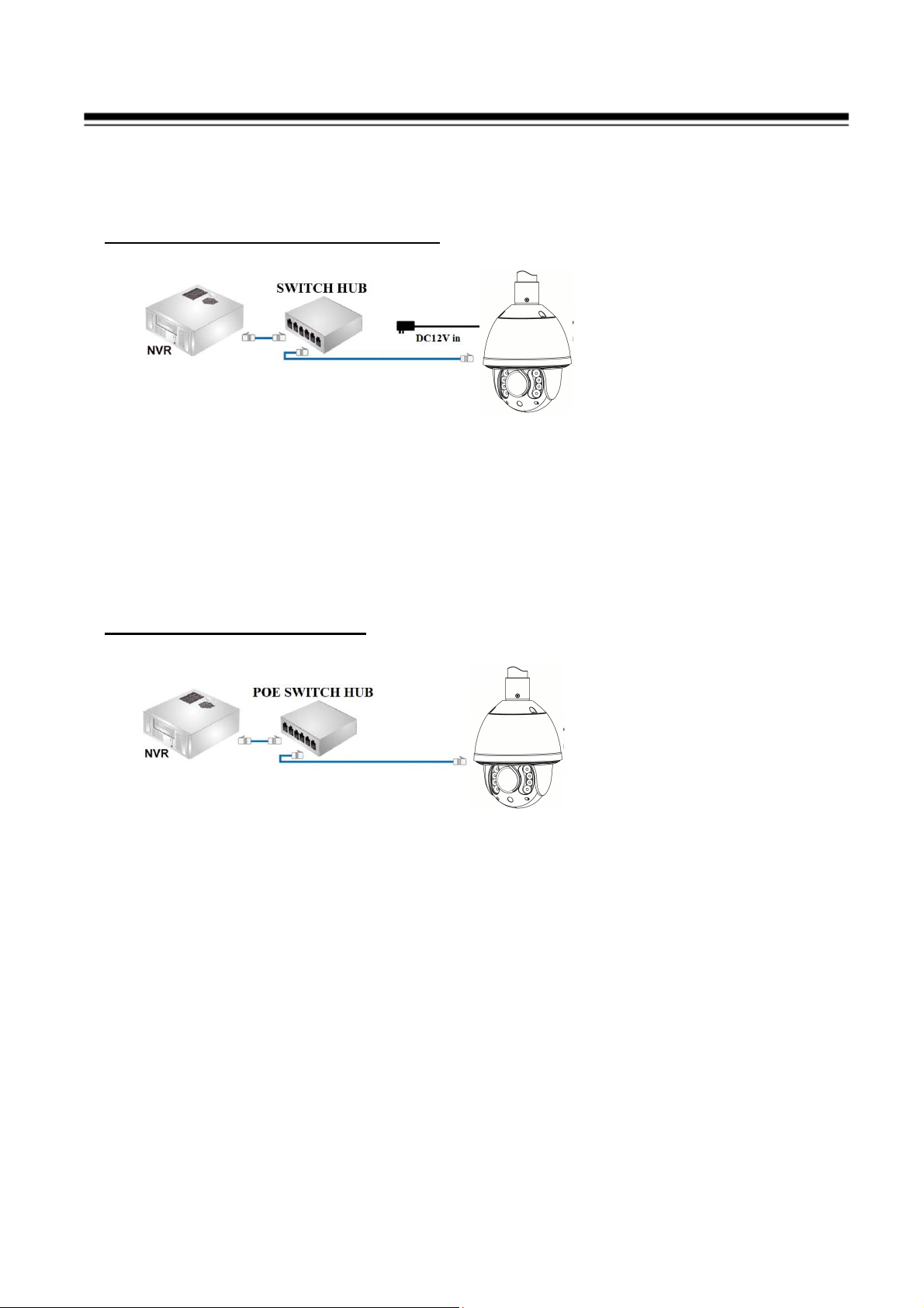
3.3 Network Deployment
General Connection (without PoE)
1. Connect RJ45 Ethernet cable to a switch. Use a Category 5 Cross Cable when
your network camera is directly connected to PC.
2. Connect the power cable from the Network Camera to a power outlet.
3. If you have external devices such as sensors and alarms, make the connection
from the general I/O terminal block
IP PTZ Camera
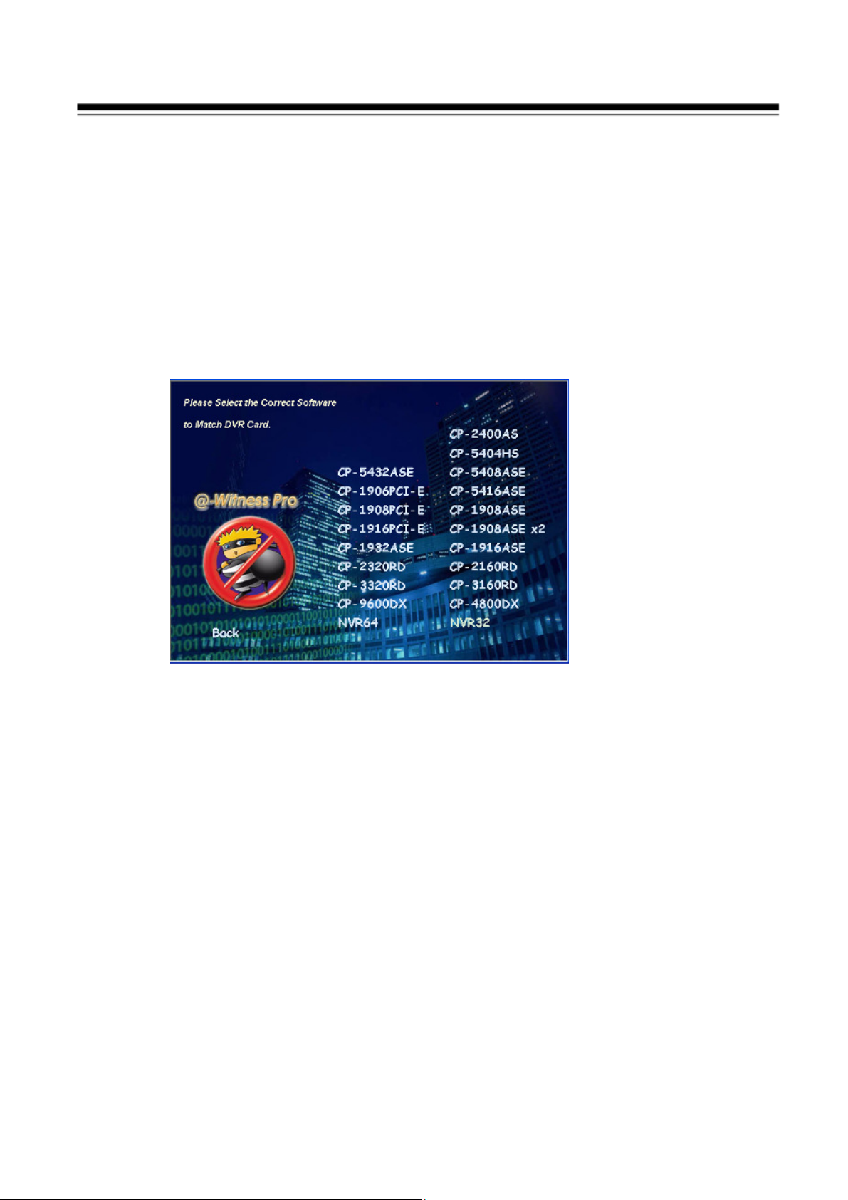
Power over Ethernet (PoE)
IP PTZ Camera
The Network Camera is PoE-compliant, allowing transmission of power and
data via a single Ethernet cable. Follow the above illustration to connect the
Network Camera to a PoE-enabled switch via Ethernet cable.
20
Page 22
4. Running IP Camera by Witness Pro NVR software
4.1 Install Witness Pro NVR software
You can use your new Network IP Camera by its web user interface v There is a
NVR software CD comes with IP camera which allow you run 32/64 channels
IP cameras on a PC. Please follow the steps below to complete the installation
of Witness Pro NVR software.
Step 1. While into Windows, and insert the I-View DVR software CD into a
CD/DVD drive
Step 2. Select the NVR64 or NVR32 software.
Step 3. Select the installation language and press the “OK” button to continue.
Step 4. Press the “Next” button to start the installation process..
Step 5. Click the “Browse” button to install into a different directory,
otherwise click on the “Next” button to install the software into the
proposed director.
Step 6. Select “No, I will restart my computer later” and press on the
“Finish” button to exit.
21
Page 23
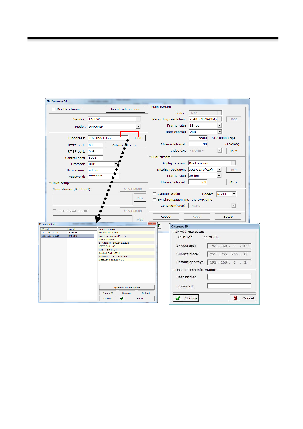
Fig A
Fig B
4.2 Setting IP camera for Witness Pro NVR software
Click “ Start “ >> “ All Programs” >> “Witness NVR32 Pro”, then select the
“ Video Parameters setup-ezSetup” accessory program to setup the parameters.
You will see the diagram as below
Disable channel: This will disable the selected channel when enable this
function.
Install video codec: Install the video codec, if you connect IP camera at first
time.
Vendor & Model: Select the correct brand and model for the connected IP
camera. You also can select “Onvif” if your IP camera support Onvif
22
Page 24

compliant and not on the list. You can check the used camera support Onvif
compliant from: http://www.onvif.org. Click “ Onvif setup “ icon to setup the
parameters which you want to run on the Hybrid DVR or NVR.
Compress: Select the suitable codec for video recording and transmission.
Recording resolution: Select the resolution for video recording and display.
Frame rate: Select the frame rate for video recording and display.
Rate Control: You can choice video quality or bit rate from this tab. Good
video quality or large bit rate request bigger storage capability.
IP address: Entry the correct IP address for the connected IP camera. If you
do not know the IP camera’s IP address, you can click “Find” icon to find out
the currently connected IP cameras
User name & Password: The user name and password must be matched the
setting of IP camera which you want to connect.
The default User name / Password is “ admin / 123456 “ and IP address is
192.168.0.123. Some special issues to cause cannot find out the IP address
that you can try the 192.168.123.123
Find: Click this icon to find out all the currently connected IP cameras on the
list. You will find out the network information of each IP camera. Please
refer the diagram shown as above Fig A. Click the IP address and “Select”
icon, the IP camera information will be show on.
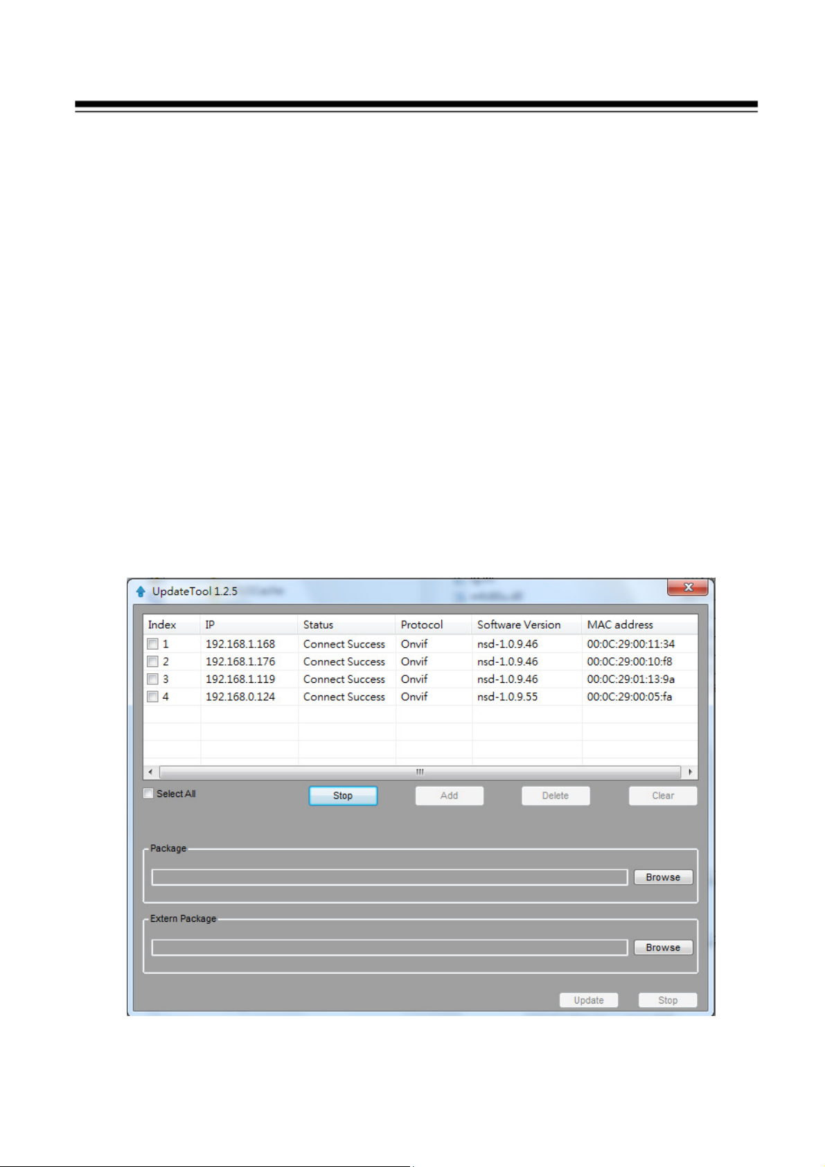
System Firmware update: Click “System Firmware update icon” icon
to update the newest IP camera firmware; you can check and download the
newest firmware version from our website: www.i-view.com.tw .
Change IP: Click “Change IP” icon to setup the DHCP or Static IP
address and also modify the username /Password. Please refer to Fig B
diagram. After modification, click “Change” icon to confirm the setting.
Discover: Click “Discover” icon to research the IP address of system.
Reboot: Click “Reboot” icon to restart this IP camera.
Go Web: Click this icon to enable the I.E. Browser to check/setup the
detail parameters.
Select: Choice the IP camera which you find out from the system and then
click “Select” icon to assign this IP camera into the camera channel of
Witness NVR.
Advance setup: Click this icon will enable the detail parameters setting of IP
camera. You need to load the Active X if this NVR is activated this process at
first time.
23
Page 25
The difference IP camera brand has its own “Find” and “Advance setup”
setup diagram and setting process. For the detail information, please refer to
the IP camera operation menu.
HTTP port & RTSP port: The both port number must be matched the setting
of IP camera..
Display streaming: You can select the “Dual streaming” or “Same as
recording” mode; If you select the “Dual streaming” mode, the live display
video will show lower resolution (320*240) for split video and higher
resolution (same as recording resolution; such as 1920*1080) for pop-up to
single video on the screen. This Dual streaming mode for live display can
save a huge CPU loading when decoding the video streaming.
Capture audio: You can record sound by microphone from audio input port
of IP camera.
Synchronization with the DVR time: Check to synchronize the time of IP
camera with DVR.
Condition (AWB): Choice the parameters to suit for the camera install
location.
Reboot: Click this icon will reboot the IP camera. .
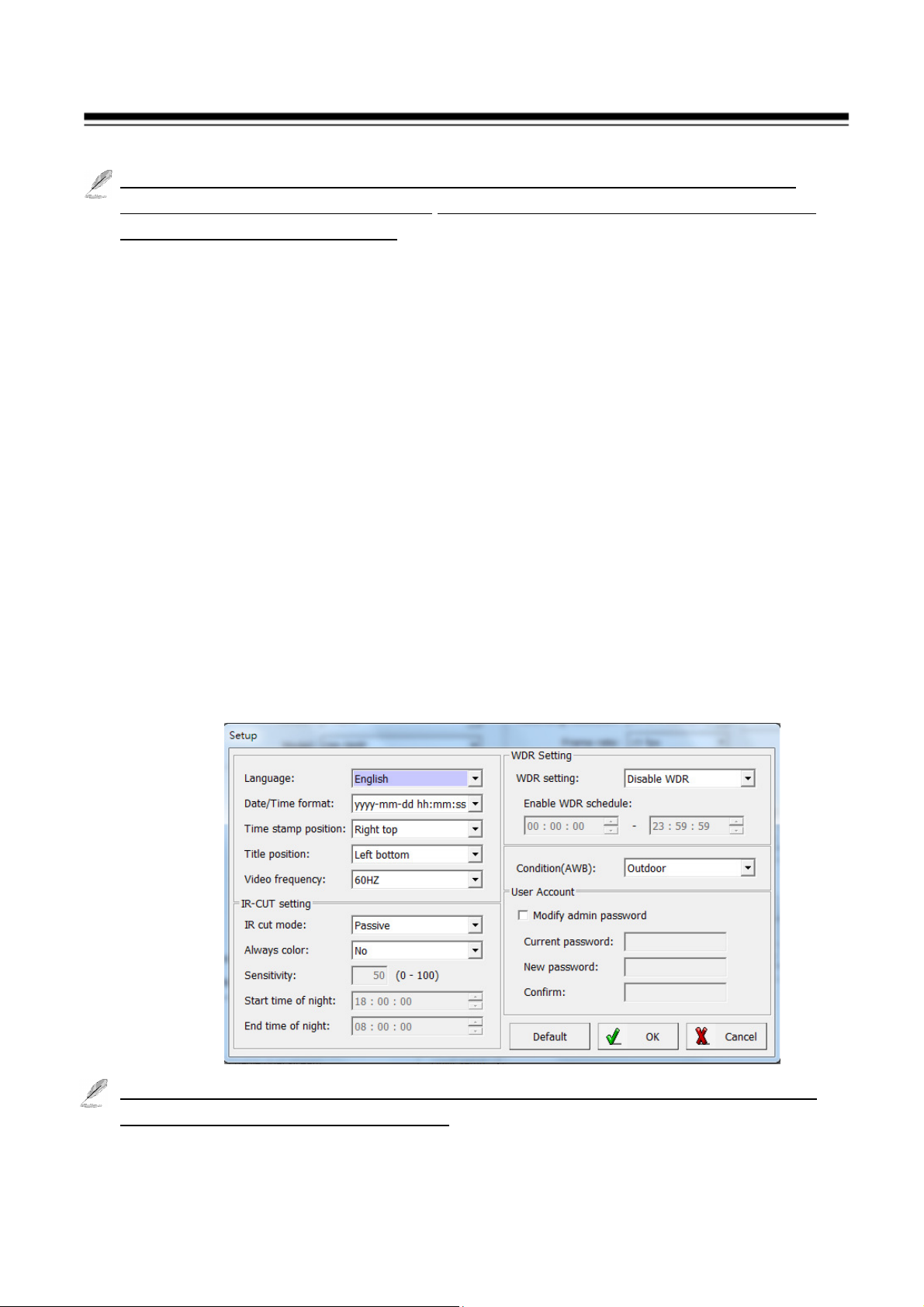
Setup: Click this icon for detail setting of IP camera; you may not need to I.E.
Browser for the detail IP camera setting. Please refer the diagram as below
(For I-View’s IP camera only):
The detail NVR software operation, please refer to the Witness Pro software
operation file which built in the CD.
24
Page 26
5. Running IP Camera by I.E. Browser
You can use your new Network IP Camera by its web user interface via I.E. web
browser.
The requirements for viewing IP camera are as below:
OS: Microsoft Windows 2000/XP/Vista/7/8.
Browser: IE6 or above.
Cell phone: 3GPP player.
Chrome V3.0 or above with plug in.
You must know the IP address of IP Camera before you can connect to it. The
IP Camera will use DHCP server on your local network to obtain an IP address
automatically by default. So, you can check your DHCP server’s IP address
lease table to find the IP address of IP Camera or also can use the utility
program ‘IPSerch.exe’ to find the IP address of IP Camera, which is come with
the CD-ROM.
Please follow up the processes as below to find out the IP address of IP camera
by IPSearch utility.
Step 1. Click “IP Search Tool.exe “program will show the window as below.
25
Page 27
Step 2. Press “Search “button to search for all IP Cameras on your local
network.
Step 3. If you need to change IP address, double click the Mouse on the
selected IP Camera and then change the IP address and Gateway IP,
then click the “OK” button to save the setting.
Step 4. If you no longer need to use this utility, click “Exit” button to close it.
1.The default User name / Password is “ admin / 123456 “ and IP address is
192.168.0.123.
2.Make sure all IP Cameras are powered on and connect to local network
first.
If you have several network connections, please disable connections that are
not connected to IP camera, otherwise the IP Search Tool.exe program may
fail to search IP camera.
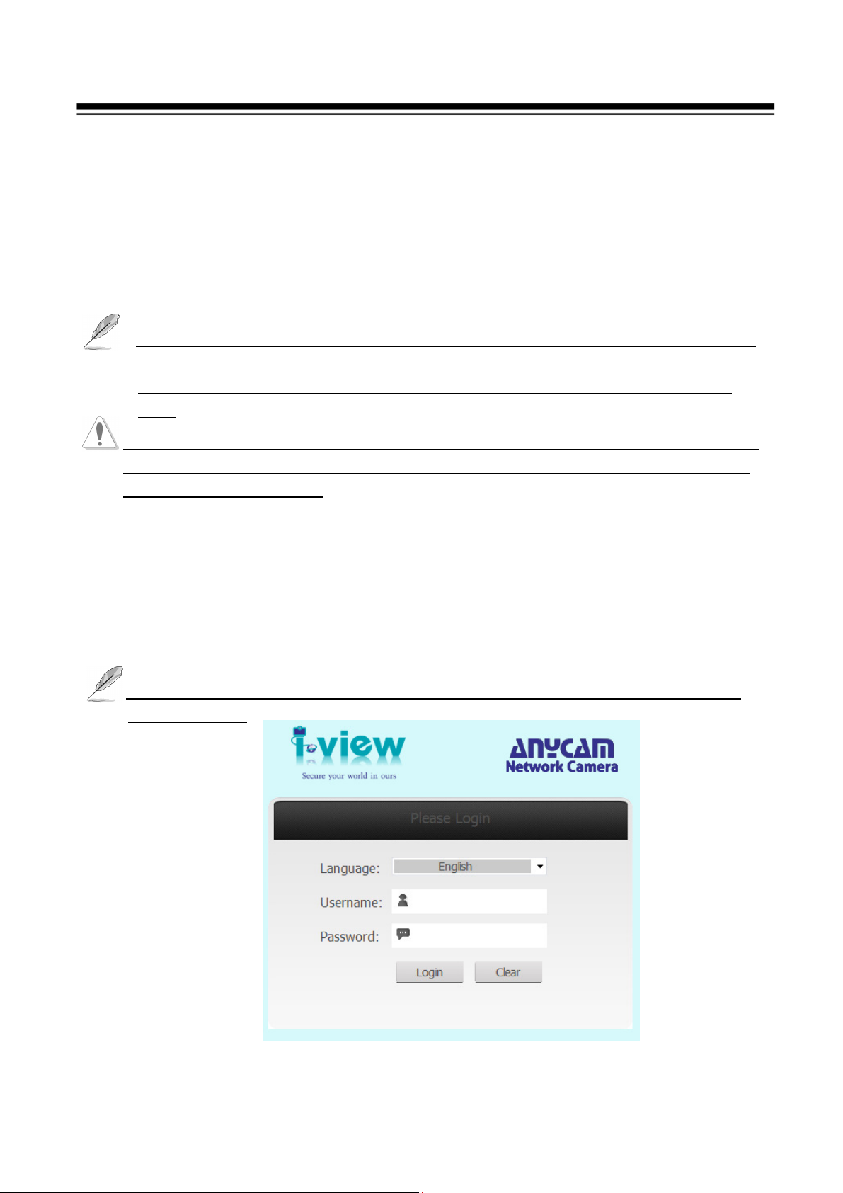
5.1 Install ActiveX Plug-in on I.E. Browser
You can connect to the IP camera by Internet Explorer or other web browsers for
remote viewing by entering IP address in address bar. When you connect to IP
Camera, the use login screen will appear when you get connected. Please
entry the user name / password to login.
The default User name / Password is “admin / 123456 “ and IP address is
192.168.0.123
26
Page 28

If you connect to IP Camera first time, you’ll see the following message; this
message prompts you that you need to install ActiveX plug-in before you can
see the video from IP Camera.
IE 8 and earlier version:
Right click the indication bar and click: “Install This Add-on for All Users on
This Computer…” to install ActiveX plug-in.
IE 9 version:
Click ‘Install’ button located at the bottom of I.E. to install ActiveX plug-in. If
you’re prompted that the Windows Firewall has blocked some features of this
program’. Click “Allow access” button to enable the IP Camera function
properly. When you’re installing Internet Explorer plug-in, you may also be
prompted the diagram. Please click “Yes” to allow changes.
27
Page 29

IE 10 version:
Click ‘Install’ button located at the bottom of I.E. to install ActiveX plug-in.
You need to do the process as below:
Click “Internet options” section, then choice “ Security “ tab >> “ Trusted
sites “ and change the bar to “Low”. Click “ Sites “ to add the trusted site for
this IP camera. Please refer to the diagram.
28
Page 30

5.2 The Function Description of Live Window
After ActiveX plug-in is installed, you should be able to see the live video from
IP camera as below window.
1
2
3
4
5
6
7
8
9
10
11
1
This section introduces the function buttons of live window. You can test the IP
camera function from your Brower. The button functions are as below:
1. Listen: Click this icon to listen the audio from IP camera when Microphone
had installed.
2. Information: This section will show the information of IP camera such as
resolution, bit rate and frame rate.
3. Talk: Click this icon to talk to IP camera when Speaker with audio Amplifier
had installed.
4. Photo: Click this icon to take a photo from IP camera. The default path is
C:\WebData\snapshot.
5. Rec.: Click this icon to start recording the video clips from IP camera; click
12
29
Page 31

Scan,
Preset
, Tour function
Preset, Tour function
again will stop recording. The default path is C:\WebData\record.
6. Screen: Display video of IP camera on the screen.
7. Screen: Choice the video streaming on the screen.
8. View: Click this icon to display the video of IP camera.
9. Play Mode: Click this icon to choice the display speed or video quality will
be priority first.
10. Setup: Click this icon to setup the parameters of IP camera.
11. Pan/Tilt/Zoom button: Move the Pan/Tilt/Zoom position of IP Speed dome
camera, this function just effect for the IP PTZ camera only and the detail
description as below.
12. Exit: Click this icon to exit the I.E. browser viewing.
Control the IP PTZ camera (FDMO-2MIP-20XIR)
Function description:
Enable the Track, Patten,
Use the left key of mouse
to click and drag a
rectangle area in the
lower right direction,
then the dome system
will move the position to
the center and allow the
rectangle area to zoom in.
Use the left key of mouse
to drag a rectangle area in
the upper left direction to
move the position to the
center and allow the
rectangle area to zoom
out.
Add/Delete/Call the Enable
the Track, Patten, Scan,
Move the Left/ Right/ Up/
Down of PTZ camera
position via these buttons
Increase /Decrease the Pan/
Tilt/ Zoom speed
Press “+” for Zoom in,
Focus near and IRIS close.
Press “-” for Zoom out,
Focus far and IRIS open
Press to turn on IR LED;
press again to turn off
Increase /Decrease the
Pan/ Tilt/ Zoom speed
30
Page 32

Setup the Preset, Tour, Scan and Track function:
Setup Preset position:
1. Move the IP speed dome Pan/Tilt/Zoom to position which you want to
setup preset position.
2. Drop the menu from the Type section, and then select the Preset item.
3. Click Add (Delete) icon to create (delete) a Preset position.
4. Select Preset ID and then entry the Preset name.
5. Click “ Save” button to save the Preset position.
6. Repeat 1-5 to setup another preset position.
The “95 preset” for OSD function, the others command codes, please
refer to the Main Functions Fast Call Table.
31
Page 33

Setup Tour :
1. Select Tour ID and then entry the Tour name.
2. Drop the menu from the Type section, and then select the Tour item.
3. Click Add (Delete) icon to create (delete) a Tour ID.
4. Choice the Preset number and then click ’Add’ button, repeat this
process to add more preset ID for tour scan.
5. Click “ Save” button to save the Preset position.
Setup Scan :
1. Select Scan ID and then entry the Tour name.
2. Drop the menu from the Type section, and then select the Scan item.
3. Click Add (Delete) icon to create (delete) a Scan ID.
4. Move the IP speed dome Pan/Tilt/Zoom to the position which you want
to setup for the begin position, then click “ Begin” button.
5. Move the IP speed dome Pan/Tilt/Zoom to the position which you want
to setup for the end position, then click “ End” button
Setup Track :
1. Select Track ID and then entry the Track name.
2. Drop the menu from the Type section, and then select the Track item.
3. Click Add (Delete) icon to create (delete) a Track ID.
4. Click “ Begin” button and then start to move the Pan/Tilt/Zoom
continually (Maximum is 500 seconds ).
5. Click “ End” button when you want to stop the track scan.
Run the Preset, Tour, Scan and Track function:
Please follow up the process as below to run the Preset, Tour, Scan and
Track function
1. Drop the menu from the Type section, and then select the Preset or
Tour or Scan or Track item.
2. Select the Preset or Tour or Scan or Track ID which you want to run
from Name section.
3. Click Call icon to start run the Preset or Tour or Scan or Track
function.
4. Click “-” of IRIS icon to stop the Preset or Tour or Scan or Track
function.
32
Page 34

5.3 Operation Instructions
1) Main Functions Fast Call Table
Our IR IP Speed dome supports 220 preset positions. You can activate some
special functions by calling upon Fast Code number 65-99.
Serial
No.
1
2
3
4
5
6
7
Command Fast Call Up Note
Default to start auto scan
Start Auto Scan Call 99
of group No.1
Default to start auto cruise
Start Auto Cruise Call 98
of group No.1
Default to start pattern
Start Pattern Tour Call 97
tour of group No.1
Start Auto Scan of
Group No.
Call 80+ Call pp+
Call 99
pp means:Group No.1-8
Start Auto Cruise
of Group No.
Start Pattern Tour
of Group No.
Call 80+ Call pp+
Call 98
Call 80+ Call pp+
Call 97
pp means:Group No.1-4
Stop Auto
Mode/End up
Call 96
Setting
8
Open OSD Menu
95)
Preset 95(or Call
9
Remote Reset Call 94
Recover Factory
10
Call 82
Default
2) System Self-Testing
The dome will do self-testing after power up, and system status will show
“Normal” if system Is running normally. If error happens, testing result will be
shown in “○” or “X”. “○” means normal and “X” means error. Please check the
according meaning as follows:
33
Page 35

3) OSD Menu Operations
Call Preset 95 to enter the main OSD menu (or call preset No.1 two
times continuously within two seconds).
Control the joystick to move the cursor around the menu.
Press “IRIS Open” or IRIS “-“ icon of Software to enter the menu for
selections.
Move the joystick up and down to select the item.
Press “IRIS Open” or IRIS “-“ icon of Software to confirm the
selection.
Press “Close” of IRIS or IRIS “+“ icon of Software to cancel the
selection.
If your controller does not have a joystick, use the up or down key or
control via the software.
34
Page 36

5.4 The Network setup Function Description
Click “Setup “ icon to start setup the parameters of IP camera. You can
configure basic IP camera settings like data transfer protocol, storage folder etc.
Device Info: Click this button to check the current Mac number, Firmware
version, model, and also allow you entry the camera name on the “Device
name:” tab. Click Save to change the setting.
Manage Device: Click this button to setup the parameters of IP camera and
the detail description as below:
35
Page 37

IP Property: Click this button to modify the current Internet protocol with
IPv4 or IPv6, IP address, enable/disable DHCP and DNS IP address. The
settings must be properly configured before you operate the IP camera over
network. IPv4 and IPv6 are both supported. Configure the NIC settings,
including the IPv4(IPv6) Address, IPv4(IPv6) Subnet Mask and IPv4(IPv6)
Default Gateway. Click Save to change the setting.
1. If the DHCP server is available, you can check to automatically obtain an
IP address and other network settings from that server.
2. The valid value range of Maximum Transmission Unit (MTU) is 500 ~
9676.
3. The Multicast sends a stream to the multicast group address and allows
multiple clients to acquire the stream at the same time by requesting a
copy from the multicast group address.
4. Before utilizing this function, you have to enable the Multicast function
of your router and configure the gateway of the network speed dome.
5. If the DNS server settings are required for some applications (e.g.,
sending email), you should properly configure the Preferred DNS Server
and Alternate DNS server.
6. The router must support the route advertisement function if you select
Route Advertisement as the IPv6 mode.
PPPoE: If you have no router but only a modem, you can use
Point-to-Point Protocol over Ethernet (PPPoE) function. Click this button
to enable the PPPoE function, Enter User Name, Password, and IP address
for PPPoE access, then Save to change the setting and exit the interface.
36
Page 38

Device Port: If there is a router and you want to access the speed dome
through Wide Area Network (WAN), you need to forward the 3 ports for the
IP Camera. Click this button to modify the HTTP (Default is 80), RTSP
(Default is 554) or Control Port number (Default is 60000) and click Save
to change the setting.
QoS: Click this button to adjust the QoS (Quality of Service) volume and it
can help solve the network delay and network congestion by configuring the
priority of data sending the audio and video and control command. The
valid DSCP value ranges from 0 to 63. The DSCP value is bigger, the
priority is higher. Click Save to change the setting.
Make sure that you enable the QoS function of your network device (such as
a router) and it will ask for a reboot for the settings to take effect.
37
Page 39

Timing: Click this button to setup the time of IP camera. The detail process
description as below:
Time Zone setup: Configuring Time Synchronization Manually. When the
IP Camera is taken to another time zone, you can use the Time Zone
function to adjust the time. The time will be adjusted according to the
original time and the time difference between the two time zones.
From the Time Zone drop-down menu to select the Time Zone in which the
speed dome locates.
Use DST: If there is the habit of adjusting clocks forward in your country in
certain time period of a year, you can turn this function on. The time will be
adjusted automatically when the Daylight Saving Time (DST; Summer time)
comes. Configuring DST process as below steps:
(1) Check to enable the DST function
(2) Set the date of the DST period then click to save the settings.
Manual setup: Configuring Time Synchronization Manually.
(1) Check the Manual Time checkbox.
(2) Click to set the system time from the pop-up calendar and then click to
38
Page 40
save the settings.
You can also click the Save icon with computer time checkbox to synchronize
the time of the IP Camera with the time of your computer.
PC Time: Select this item and IP camera will synchronize the Date/ Time
with your computer’s (or NVR) time as its time. Click the Save icon for
save the setting.
NTP Server: You can follow the instructions in this section to configure the
time which can be displayed on the video. There is Time Zone, Time
Synchronization, Daylight Saving Time (DST) functions for setting the time.
Time Synchronization consists of auto mode by Network Time Protocol
(NTP) server and manual mode. Configuring Time Synchronization by
NTP Server
(1) Check the checkbox to enable the Use NTP function.
(2) Entry IP address of NTP server and port of NTP server, 123 by default.
If the IP Camera is connected to a public network, you should use a NTP
server that has a time synchronization function, such as the server at the
National Time Center (IP Address: 210.72.145.44). If the IP Camera is set in
a customized network, NTP software can be used to establish a NTP server
for time synchronization.
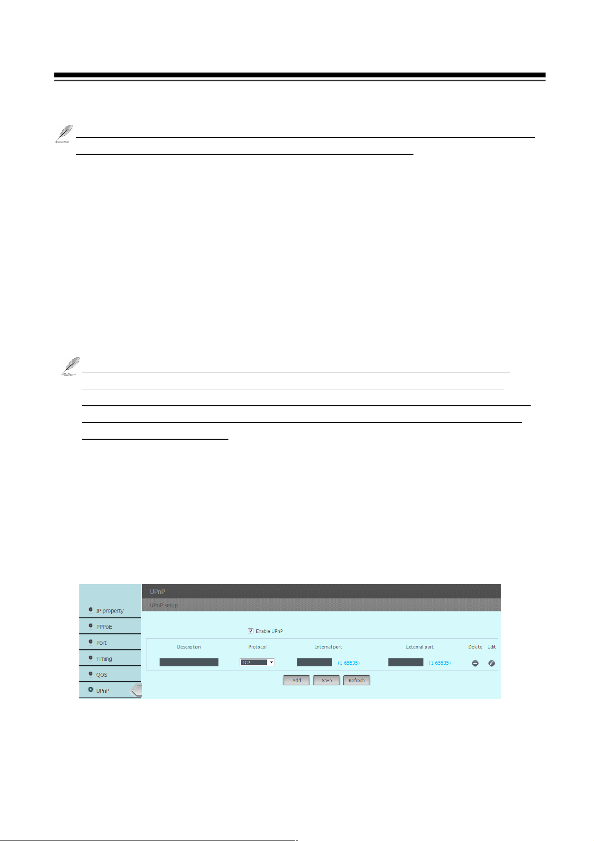
UPnP: Click this button to enable the UPnP (Universal Plug and Play)
function. UPnP™ is a networking architecture that provides compatibility
among networking equipment, software and other hardware devices. The
UPnP protocol allows devices to connect seamlessly and to simplify the
implementation of networks in the house and corporate environments. With
the function enabled, you don’t need to configure the port mapping for each
port, and the camera is connected to the Wide Area Network via the router.
1. Check “Enable UPnP™ icon from settings interface.
39
Page 41

2. Click Edit icon to select the Protocol and then entry the Internal/External
Port.
3. Click Add icon to increase this port. Repeat the 1-3 to add another port.
4. Click Save icon to save the setting.
You can edit the Friendly Name of the IP Camera. This name can be detected
by corresponding device, such as a router.
DDNS: Click this button to setup the DDNS function, there are three
default DDNS server for the user choice. If your IP Camera is set to use
PPPoE as its default network connection, you can use the Dynamic DNS
(DDNS) for network access.
Before you start, please registration on the DDNS server is required before
configuring the DDNS settings of the IP Camera. Please do the process to
setup the DDNS.
(1) Enter the DDNS Settings interface:
(2) In the Domain text field, enter the domain name obtained from the DDNS
website.
(3) Enter the Port, User Name, Password registered on the DDNS website and
the check interval period of DDNS server. Click to save the settings.
40
Page 42

SMTP: The system can be configured to send an Email notification to all
designated receivers if an alarm event is detected, e.g., motion detection event,
video loss, tamper-proof, etc.
Before you start, please configure the DNS Server settings before using the
Email function.
1. Enter the Email settings interface:
2. Configure the following settings:
Sender: The name of the email sender.
Sender’s Address: The email address of the sender.
SMTP Server address: The SMTP Server IP address or host name
(e.g.,smtp.263xmail.com).
SMTP Port: The SMTP port. The default TCP/IP port for SMTP is 25.
Transport Mode: Enable SSL function; please check the SSL if it is required
by the SMTP server.
Receiver email address: Entry the receiver email address and then
3. Click to save icon to save the settings.
Mobile Phone Viewer: Click this button to enable IP camera for the
mobile or Table PC remote viewing, this function can suit for the Android,
iPhone Mobile phone and i-Pad Table PC. Entry the UID number or scan QR
41
Page 43

code into your mobile App, then you can remote viewing /Recording the IP
camera video and also can control the PTZ IP camera. .
Media Configuration: Click this button to setup the media parameters of IP
camera and the detail description as below:
42
Page 44

Streaming: Configuring Video streaming settings as below:
The RTSP command code as below: Main streaming: RTSP://IP
Address:554/media/live/1/1 Sub streaming: RTSP://IP
Address:554/media/live/1/2
Source Resolution: Select video main streaming resolution from the drop
menu.
Streaming ID: Streaming 1 means is the “ Main Streaming “ that for the
recording purpose. The streaming 2 means is the “ Sub streaming” that is
for the remote viewing from Internet when bandwidth is not enough or split
video display to reduce the system loading.
Video Encode: The Video Encoding standard can be set to H.264 or MJPEG.
You can set the profile level to High Profile, Main Profile or Basic Profile
for H.264 encode.
Audio Encode: There are G7.11 u Law /a Low compression. G.711ulaw
selectable.
Resolution: Choice the video streaming resolution for display and recording.
I-Frame interval: It is the least compressible but doesn't require other video
frames to decode. Less number of I-Frame intervals will get less size of
video streaming, but the video quality will be worse when image change rate
is high.
Frame rate: The frame rate is to describe the frequency at which the video
stream is updated and it is measured by frames per second (fps). A higher
frame rate is advantageous when there is movement in the video stream, as it
maintains image quality throughout.
VBR (Variable Bit Rate): VBR files vary the amount of output data per
time segment. It allows a higher bitrates (and therefore more storage space)
to be allocated to the more complex segments of media files while less space
is allocated to less complex segments.
CBR (Constant Bit Rate): The rate at which a codec's output data is
constant. CBR would not be the optimal choice for storage as it would not
allocate enough data for complex sections (resulting in degraded quality)
while wasting data on simple sections.
Bit Rate mode: Set the max. Bitrate to 200~12000 Kbps. The higher value
corresponds to the higher video quality, but the higher bandwidth (file size)
is required.
43
Page 45

Quality: hen bitrate type is selected as Variable, 9 levels of video quality are
selectable. The higher will get better video quality, but the higher file size.
Save: Click Save icon to save the setting parameters.
Video setup: Setup set the image quality of the IP Camera, including
brightness, contrast, saturation, sharpness, etc. The detail deception as
below:
Basic setup: Adjust the video parameters such as Brightness, Saturation,
Sharpness and mirror function. .If you turn the Mirror function on, the
image will be flipped. It is like the image in the mirror. The flip direction
can be set to off, horizontal and vertical mirror position.
Exposure: Provides auto and fixed mode, the max value of shutter needs
to be adjusted manually. This function can be used in underexposure
condition. It lengthens the shutter time to ensure full exposure
Gain: Provides auto and fixed mode, the value of gain needs to be
adjusted manually.
Scene setup:
White balance: There are some scene modes to difference
environments, such as Auto, Cloudy, Sunny, Tungsten and Fluorescent
mode
WDR: Allow to enable /disable WDR function.
44
Page 46

Flickless: Set the Video Standard to 50hz(PAL) or 60hz(NTSC) according
to the video system in your country, Wrong frequency will show the
scrolling lines on the video.
Noise reduction: The noise reduction function processes the noise
between two frames besides processing the noise in one frame. The noise
will be much less and the video will be clearer Choice the volume of
noise reduction level high will show less noise but the image become
fuzzy.
WDR: Allow to enable /disable WDR function.
IRIS: Provides auto and fixed mode, the value of iris speed needs to be
adjusted manually.
D/N configure: Provides auto and fixed mode, allow adjust IRIS speed
for application.
D/N mode: Enable “ Passive “ mode and keep on the “Black &
White” mode of Night color tab when you use IR type IP camera and
none IR LED camera select the “Active” mode.
Sensitivity: Choice “ Higher” mode turn into the B/W at high
Illumination. Click Save icon to save the setting.
45
Page 47

OSD: Allow to paste text (Device name) and time stamp on the video.
Basic setup: You can choice the font size and transparency for the text
(Device name) and time stamp which you want to show on the video of IP
camera.
System setup: Allow enable/disable the “Device name” and “Time
stamp” to paste on video; and you also can setup the display position.
The left/top is original position of X/Y axis.
Allow user to define the time format and paste text position.
Audio setup: Click this button to setup the audio recording, it supports the
gain from 1-100. there are 2 audio codec (G7.11 uLow and a Low modes)
46
Page 48

Privacy Mask: Privacy mask enables you to cover certain areas on the live
video to prevent certain spots in the surveillance area from being live viewed
and recorded. Enable Privacy mask function, click and drop the left button of
Mouse for setup up the mask.
Allow setup several mask areas, but the total areas cannot exceed 5% of
image.
Video system: Choice the video system for the TV out (Composite signal). .
The maximum frame rate will be 30 fps when choice the NTSC mode and
25fps at the PAL mode.
ROI: ROI (Region of Interest) encoding is used to enhance the quality of
images which are specified in advance. These ROI areas image will first
priority to send out for internet transmission when bandwidth is not enough.
The ROI mode is not effect when enable the VBR mode.
47
Page 49

I/O & PTZ setup: You can setup the alarm input/output and PTZ protocol
from this section.
PTZ: Setup the PTZ parameters such as Baud rate, protocol and ID
address. (Option)
Alarm I/O: Alarm input: Setup the name of alarm input and define the
level of trigger single.
Alarm output: Setup the name of alarm output; define the mode (NC or NO)
and trigger period. (0 ms: Continue trigger)
48
Page 50

Alarm Trigger: You can setup
the image motion trigger and
sensor alarm trigger from this
section. The detail process
show as below:
49
Page 51

Motion alarm: Enable Motion detection function and you can setup the
trigger schedule and detection area. Click and drag the left button of
Mouse to setup the detection and you also can select the motion sensitivity.
You can specify the linkage method (Such as Trigger alarm output, move
the PTZ camera preset position and notify via email) when an event
occurs.
Alarm trigger: The alarm trigger almost same as Motion alarm, please
refer the description of Motion alarm section.
Alarm interval: The trigger of alarm output will be triggered base on the
interval period.
Recording: Click this button to setup the type of triggered recording, storage
media and schedule recording. You can setup the Pre recording & Post
recording period with the video and picture format on difference storage
device. Please refer the detail process as below:
Recording: Enable the” Schedule” recording and you can select
“Continue recording “, “ Start recording when network failed” and
“ Schedule recording “ mode. As for the “ Start recording when
network failed” that will save the video clips on the SD card, please add
the SD card when you enable this recording mode.
“Triggered recording”: Setup Pre/Post recording period and maximum
period is 10 seconds.
“Recording parameters” :
Streaming ID: Select the video streaming which we want to recording.
Save mode: There are two modes “Over write when full “and “Keep
days “.
Pre-recording: The time you set to start recording before the
scheduled time or the event. For example, if an alarm triggers
50
Page 52

recording at 10:00, and the pre-record time is set as 5 seconds, the
IP Camera starts to record at 9:59:55.
Post-record: The time you set to stop recording after the scheduled
time or the event. For example, if an alarm triggered recording ends
at 11:00, and the post-record time is set as 5 seconds, the IP Camera
records until 11:00:05.
Overwrite: If you enable his function and the HDD is full, the new
record files overwrite the oldest record files automatically.
Keep days: If you enable his function and the HDD is full, the new
record files will be stop save into the HDD when the storage days
over your setup volume of Keep days.
Make sure the size of storage media allow to save video clips which setup
volume of “Keep days” mode.
51
Page 53

Record path: Select the recording media via FTP server or SD card.
To configure record settings, please make sure that you have the network
storage device within the network or the SD card inserted in your IP
camera.
“FTP server”: Setup the recording path via FTP server mode. The
detail information of FTP server, maybe need to ask the MSI people.
“SD Card ”: Setup the recording path on SD Card.
You need to format the SD card from the IP camera before you used.
Local path: Setup the saving path of video clips and snapshot on the
PC which connect this IP camera.
52
Page 54

Authority: Setup authorized users and group from this section.
Group: Define the privilege of Group user, there are three levels Group:
Administer, Operator and Media user.
User: Click this button to create a new user or delete/ modify available
user. There are three user accounts, Media user, Operator and
Administer.
Protocol: The IP camera support the Onvif protocol and you will find out the
version.
53
Page 55

Maintenance: Click this button
to update the firmware, restore
the default setting and check the
view log …etc. Please refer the
detail process as below:
Reboot: There are 2 choices to reboot the IP Camera, one is menu, the
other by schedule setting.
Click the “Reboot” icon and the IP camera will reboot, this process will
take 1-2 minutes.
Enable the “Auto reboot” icon, you can setup the reboot schedule to
reboot the IP camera at a specific time. The schedule can be every day
or one day per week. As this process that will keep on the IP camera at
the optimum status.
Reset: You can choice reset the IP
address or all parameters become to
the default setting. Click the
“ Reset IP address “ icon just let the
IP address only become to default
only, the reset parameters will keep
the used setting. Click the “Reset
54
Page 56

“ icon the IP camera setting become to default.
Clicking Reset icon will restores all the parameters to default settings
including the IP address and user information. Please use this button with
caution.
Even Log: Click this icon to search the even log, you can entry the specific
period and event then click “Search “ icon. The even log detail information
will display on the window.
System upgrade: Click this button to upgrade IP camera’s firmware. Click
‘Browse’ button to select a firmware image file on your computer first, then
click ‘Update’ button. The IP camera will auto reboot after update the
Firmware. You can choice reset the parameters become to the default setting
or not when you update the Firmware.
The upgrading process will take 1 to 3 minutes. Please don't disconnect
power of the IP Camera during the process. The IP Camera reboots
automatically after upgrading.
55
Page 57

6. OSD Menu Functions
56
Page 58

LANGUAGE
The language for the on-screen menus is
Selectable.
To change the display language:
Press Iris Open to enter selection.
All on-screen menus are changed to the selected
language.
57
Page 59

SYSTEM INFORMATION
The user can check the dome system information as
required. The system information includes: Dome ID,
dome address, baud rate, protocol, temperature,
voltage, alarm info, dome title, version, date, time,
and temperature scale.
Use the following steps to display the System
information screens:
1. Use the joystick to position the cursor along the
SYSTEM INFORMATION.
2. Press Iris Open. The SYSTEM INFORMATION
screen opens.
3. Mover the joystick up and town to select the item.
4. Press Iris Open to enter the setup of each item.
58
Page 60

DISPLAY SETUP
Display setup allows the user to define the way to
display the dome titles on the monitor.
The displayed titles are listed as follows:
DOME TITLE: Indicate dome
PRESET: Indicate the dwell time for preset title
MOTION: Indicate the dwell time for auto
function titles (auto scan/auto cruise/pattern tour)
ZONES: Indicate the dwell time for zone titles
DATE/TIME: Display the current date and time
PAN/TILT: Time to display PTZ and zoom info
OTHERS:
ALARM: Time to display alarm in/out info
IR LED INFO: Time to display IR LED info
PROMPT: Display/Disappear prompt info of
Dome Title and Date/Time.
Other setup selections include:
OFF: Title will not be displayed when activated.
ON: Title will be continuously displayed.
2 /5/10SEC: Title will be displayed for 2/5/10
seconds after activation
Move the cursor by joystick to the one you need
to set, and press Open key of IRIS to enter the
item. Move the joystick select the status and
press Open key again to confirm.
Titles can be placed anywhere on the monitor.
This feature allows you to customize the window
of your monitor screen. To set a title position:
a.) Move the cursor via joystick to the DISPLAY
POSITION, then press Open of IRIS
b.) Use the joystick to move the title up, down, left,
or right; then press Open key to confirm.
c.) Move cursor at BACK or EXIT and press OPEN
key to save settings and exit menu.
59
Page 61

IR LED
The user can open and close the IR LED manually and set up the IR LED work
mode under this OSD mean. (Under normal operation
mode, the user can press IRIS OPEN and IRIS CLOSE to
adjust the IR LED power):
1) CONTROL MODE:
AUTO: IR LED will be opened or closed automatically
according to the light conditions.
TIMING: LED will be adjusted according to Open and
Close Time.
OPEN: IR LED forcedly open
CLOSE: IR LED forcedly close
CAMERA: IR LED status (Open/Close) will be
synchronized with Camera day and night switching
2) SENSITIVIRY:
Here the user can manually set the sensitivity from 1-5.
The smaller the number is, the lower light of the
environment will be when the IR LED on.
3) IR LED POWER: Here the use can choose the power
mode covering: NORMAL, MATCH and USER.
NORMAL: Near IR LED will be turned on when wide
angle. and Far IR LED will be turned on when small
angle.
MATCH: The Near and Far IR LED will be turned on
and off automatically to match the zoom in and out.
USER: The user can manually adjust the Near and Far IR
LED.
4) AUTO CONTROL: When it is on, the IR LED will
turn its power consumption to the standby status
which will effectively extend the service life of IR
LEDs. And under this mode, when objects appear in
the screen, the IR LED will turn its power consumption
back to the normal status.
5) STANDBY POWER: When the AUTO CONTROL is
on, the user can set up the standby power here.
6) STANDBY DELAY: Set up how long if there is not
moving object, the IR LED will turn into standby
60
Page 62

status.
7) SENSITIVITY: When the AUTO CONTROL is on, the user can set up the
sensitivity to detect the moving objects.
8) ENHANCED MODE: Under normal status, press IRIS OPEN to enhance the
IR LED power, when it is turned to maximum, press IRIS OPEN continuously
for 2 seconds to enter the enhanced mode. And the whole brightness of the
image will be improved. Move the cursor to EHNANCED MODE and press
IRIS to enter and select between” STATIC” and “DYNAMIC”
9) START/STOP TIME: Set up time for IR LED to open and close under
“TIMING” of control mode.
61
Page 63

IDLE
IDLE setting means if there is no command for the dome for a period of time, the
dome will run the actions as defined.
1) TIME: Move the cursor to “TIME” and press IRIS
OPEN to enter, and move the joystick up and dome
to select among 30 sec, 1 min, 5 min, 10 min and
30 min. And press IRIS OPEN to confirm.
2) ACTION: Move the cursor to “ACTION” and
press IRIS OPEN to enter. Move the joystick to
select the actions including” NONE, PRESET,
SCAN, SEQUENCE, PATTERN. Press IRIS
OPEN to confirm.
62
Page 64

3) ALARM
The dome system has 2alarm inputs and 1 alarm
output. (Option0. When an alarm is received, an
input signal to the dome triggers the user defined
action (such as presets, patterns, etc.), and at
meantime the alarm output signals is activated.
ALARM NO.: Move the cursor to the ALARM
NO. Press IRIS OPEN to enter and move the
joystick up and down to select the alarm input no.
(Channel 1 and Channel 2)
INPUT STATE: Set the alarm contact status.
There are two input states, OPEN and CLOSE.
OPEN: Normally open
CLOSE: Normally close
ALARM MODE
OFF: Alarm function is deactivated.
ON: Alarm function is activated.
AUTO : AUTO Alarm function will be activated
and deactivated between START and STOP TIME.
ACTION: Set the alarm action:
NONE: No action. (Default)
PRESET: Dome goes to preset. (Default Preset 1)
SCAN: Dome starts auto scan (Default Scan 1)
SEQ: Dome runs auto cruise (Default Cruise 1)
PATTERN: Runs pattern scan (Default Pattern 1)
ALARM OUT: Set the auxiliary to activate:
OFF: Not alarm output will be activated.
OUT1: Alarm action will close AUX 1 output.
OUT2: Alarm action will activate AUX2 output.
RESET TIME: Set up time for the alarm output
(such as alarm buzzed) when is triggered.
START /STOP TIME: Set up the time to start
alarm and stop alarm ONLY under the AUTO
mode under ALARM MODE.
63
Page 65

PRIVACY MASK
Privacy mask allows the user to mask the privacy
areas with black frame. The user can set up 8
privacy masks at most.
MASK NO.: Move the cursor here and press IRIS
OPEN to enter the setup of Mask Number of the
privacy zone,
ENABLE: To enable or disable this privacy mask
function.
SET: Move the cursor here and press IRIS OPEN
to enter the mode of setting the privacy mask.
Move the joystick (Left/Right/Up/Down) on the
screen to set up the privacy zone and press IRIS
OPEN to confirm.
DELETE: Move the cursor here and press IRIS
OPEN to delete the current No. of privacy mask
zone.
64
Page 66

CLOCK
The dome can display the data and time. And the
user could enter this CLOCK menu to set up the
DATE and TIME.
DATE: Move the cursor here and press IRIS
OPEN to enter. Move the joystick left and right to
choose the date position and move it up and dome
to adjust the figures. Press IRIS OPEN to
confirm.
TIME: Move the cursor here and press IRIS
OPEN to enter. Move the joystick left and right to
choose the time position and move it up and
dome to adjust the figures. Press IRIS OPEN to
confirm.
SAVE/CANCEL: Move the cursor to “SAVE”
and press IRIS OPEN to save the settings. Move
the cursor to “DELETE” and press IRIS OPEN to
cancel the settings.
65
Page 67

PASSWORD
The dome features password protection function
to prevent unanthorized changes to the dome
settings. If the PASSWORD function is enabled,
the operator can not access any dome setting
without entering a valid password.
EDIT PASSWORD: Move the cursor here and
press IRIS OPEN to enter. Please under the old
password before set up the new password. The
initial password is “111111”
ENABLE: Move the cursor here and press IRIS
OPEN to enter. Move the joystick to select
between “ON” and “OFF” . The user need to enter
the password when opening the OSD under the
status of “ENABLE: ON”.
66
Page 68

DOME TITLE
The user can set up the dome title to define each
camera. Dome title support up to 12 characters.
Move the cursor according the left steps and
select INPUT. Press IRIS OPEN to enter.
1) Move the joystick left and right to position “←”,
and press IRIS OPEN to delete the character
at“←”. Press IRIS CLOSE to exit the edit mode.
2) Move the cursor to “<CAP>” and press IRIS
OPEN to enter. Move the joystick up and down to
select the input method (such as English Cap,
English, Chinese, Figures, and Symbols)
3) Mover the cursor to next line of <CAP> and press
IRIS OPEN to enter the mode of character input.
The selected character will be shown in high
brightness. Move the joystick up/down/left/right
to choose the needed characters. Press IRIS
OPEN to move the selected character to the
INPUT position at“←”.
4) After finishing the character inputs, move the
cursor to “OK” and press IRIS OPEN to confirm.
5) Also user can move the cursor to “CANCEL” to
cancel the character input settings.
67
Page 69

SOFT ADDRESS SET
The use can set up the SOFT ADDRESS, SOFT
PROTOCOL and SOFT BAUD RATE under this
menu here to activate the soft address function. And
then the defined dome address by dip switch will be
disabled.
1) Move the cursor to INPUT (under DOME ID) and
press IRIS OPEN to enter the mode of setting
dome ID, Move the joystick to position the cursor
beside :0 1 2 3 4 5 6 7 8 9” and press IRIS OPEN
to enter. And move the joystick again to select
numbers of dome ID and press IRIS OPEN to
confirm. The number selected will be input on the
upper line.
2) Move the cursor to INPUT (the bottom menu) and
press IRIS OPEN to enter the mode of setting soft
address, Move the joystick to position the cursor
beside :0 1 2 3 4 5 6 7 8 9” and press IRIS OPEN
to enter. And move the joystick again to select
numbers of dome soft address and press IRIS
OPEN to confirm. The number selected will be
input on the upper line.
3) Enable or disable the soft address function. Press
IRIS CLOSE to exit last step. Move the cursor to
to “SOFTADDRESS:ON/OFF”. Press iris open to
enter. Move the joystick up or down to select ON
of OFF. Press IRIS OPEN to confirm.
4) Press OK to save and confirm all the settings and
press CANCEL to exit all the settings.
68
Page 70

AUX
The user can set up the auxiliary output to trigger
other devices from an alarm or a controller.
Move the cursor to AUX and press IRIS OPEN to
enter to select “ON” or “OFF” to enable or disable
this function.
69
Page 71
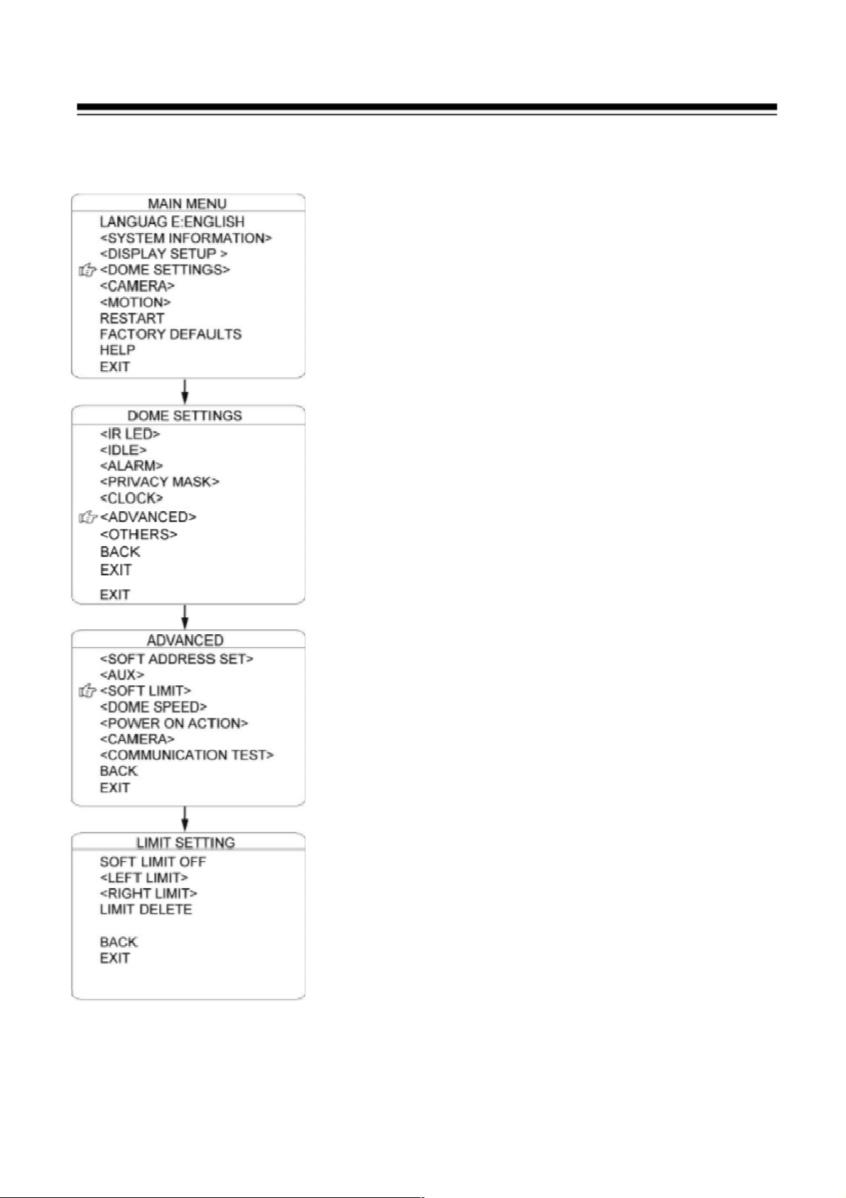
SOFT LIMIT
The user can set up the soft limit to define the left
and right boundaries for the pan movement.
SOFT LIMIT: Move the cursor here and press IRIS
OPEN to enter. Move the joystick to select “ON” or
“OFF” to enable or disable this function.
LEFT LIMIT: Move the cursor here and press IRIS
OPEN to enter. Now the user can mover the joystick
to control the PAN movement of the dome to a
defined position for the left limit. Press IRIS OPEN
to confirm.
RIGHT LIMIT: Move the cursor here and press
IRIS OPEN to enter. Now the user can mover the
joystick to control the PAN movement of the dome to
a defined position for the right limit. Press IRIS
OPEN to confirm.
LIMIT DELETE: Move the cursor here and press
IRIS OPEN to delete all the settings.
70
Page 72

DOME SPEED
To make a selection of the dome speed, the user can
enter this menu to set up.
Move the cursor to DOME SPEED and press IRIS
OPEN to enter. Move the joystick to select the dome
speed when doing the pan movement.
Move the cursor to BACK/EXIT and press IRIS
OPEN to run the command of BACK or EXIT.
71
Page 73

POWER ON ACTION
The user can define the dome action when power
on,
Move the cursor to POWER ON ACTION and
press IRIS OPEN to enter the mode of setup.
NONE: No action. (Default)
PRESET: Dome goes to preset. (Default as Preset
SCAN: Starts auto scan (Default Scan 1)
SEQ: Runs auto cruise (Default Cruise 1)
PATTERN: Dome runs pattern (Default Pattern 1)
72
Page 74

CAMERA
The dome can automatically recognize the main
camera modules in the market. For the cameras it
cannot recognize, the user can set up here.
CAMERA: Move the cursor here and press IRIS
OPEN to enter the setup mode. Move the joystick
up and down to select the camera types. Press IRIS
OPEN to confirm.
BAUDRATE: Move the cursor here and press IRIS
OPEN to enter the setup mode. Move the joystick
up and down to select the baud rate. Press IRIS
OPEN to confirm.
PARITY: Move the cursor here and press IRIS
OPEN to enter the setup mode. Move the
joystick up and down to select the parity mode.
Press IRIS OPEN to confirm.
73
Page 75

COMMUNICATION TEST
The dome can do self diagnosis for the
communications between keyboard and speed
dome. The test needs to match with our TESTING
SOFTWARE DOMETK100.
If the self testing is successfully finished via the
software, the system will show up the testing
results as left diagram.
74
Page 76

OTHERS
The user can set up TEMP MODE, INTERNAL
FAN, PRESET FREEZE, STOP TIME. MENU
OFF TIME and NORTH ZERO here under the
menu of “OTHERS”
TEMP MODE: To set up the control mode of
dome fans and heaters. It includes three modes of
AUTO, FAN HIGH SPEED and FAN LOW
SPEED.
PRESET FREEZE: This feature freezes the scene
on the monitor when going to a preset. This allows
smooth switching from one preset scene to another.
AUTO FLIP: When the camera tilts downward
and goes just beyond the vertical position, the
camera will rotate 180 degrees. The user can press
IRIS OPEN to enter and choose to turn on/off this
function.
STOP TIME: To set up the time that dome will
stops after receiving the last command. Options
include 5/15/30/60 Sec.
MENU OFF TIME: To set up the time that OSD
menu be off when no operations. Options include
1/2/5/10 min.
NORTH ZERO: To set up the due north of the
dome (pan 0º)
Move the cursor here and press IRIS OPEN to
enter. Move the joystick to control the dome to
pan 0º and press IRIS OPEN to confirm.
75
Page 77
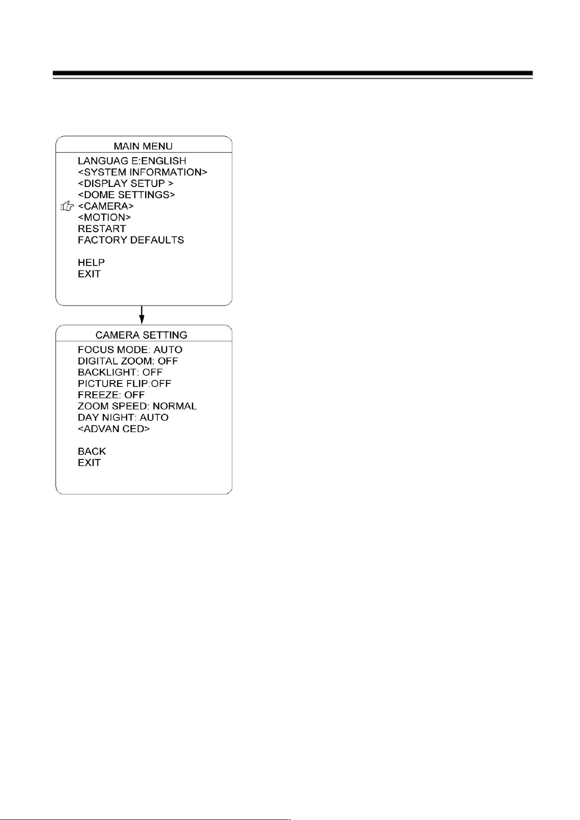
CAMERA
The user can make adjustment for the cameras
under this menu.
FOCUS MODE: AUTO FOCUS allows the
camera lens to remain in focus during zooming in,
zooming out and pan/tilt movement. Move the
cursor here and press IRIS OPEN to enter. Setup
the mode: AUTO” or “OFF” and press IRIS
OPEN to confirm. When auto focus is off, the
user needs to do manual focus.
DIGITAL ZOOM: Move the cursor here and
press IRIS OPEN to enter. Setup the function to
be “ON” or “OFF”.
BACKLIGHT: Move the cursor here and press
IRIS OPEN to enter. Setup the function to be
“ON” or “OFF”.
PICTURE FLIP: To set up the Tilt flip for the
dome. Move the cursor here and press IRIS
OPEN to enter. Setup the function to be “ON” or
“OFF”.
FREEZE: If turn on this function, the screen
image will be frozen until it is turned off. Move
the cursor here and press IRIS OPEN to enter.
Setup the function to be “ON” or “OFF”.
ZOOM SPEED: To set up the zoom speed of
Low, Normal and high when doing the zoom in
and out. Move the cursor here and press IRIS
OPEN to enter. Move the joystick to choose and
press IRIS OPEN to confirm
DAY NIGHT: To set up the day and night mode
of AUTO, CLOUR and B/W. Move the cursor
here and press IRIS OPEN to enter. Move the
joystick to choose and press IRIS OPEN to
confirm.
76
Page 78

CAMERA ADVANCED
The use can set up more detailed parameters of
camera here under the menu of CAMERA
ADVANCED.
WB: To set up the white balance of the camera.
Options include AUTO, MANUAL. INDOOR
and OUTDOOR. The use can select different
mode according the different locations.
RED GAIN: Only can be adjusted whet WB set
as manual.
BLUE GAIN: Only can be adjusted whet WB set
as manual.
BIRGHT: To set up the brightness of the image.
Move the cursor here and press IRIS OPEN to
enter. Move the joystick to adjust and press IRIS
OPEN to confirm
EXPOSURE: To set up the exposure mode of the
camera. Options include AUTO, MANUAL,
SHUTTER PRIORITY, IRIS PRIORITY and
BRIGHT PRIORITY. The use can select different
mode according the different locations.
WIDE DYNAMIC: Wide dynamic range (WDR)
balances the brightest and darkest sections of a
scene to produce a picture that is perfectly
balanced in light and clarity. Available settings
are OFF.LOW.MID and HIGH. The default
setting is OFF.
77
Page 79
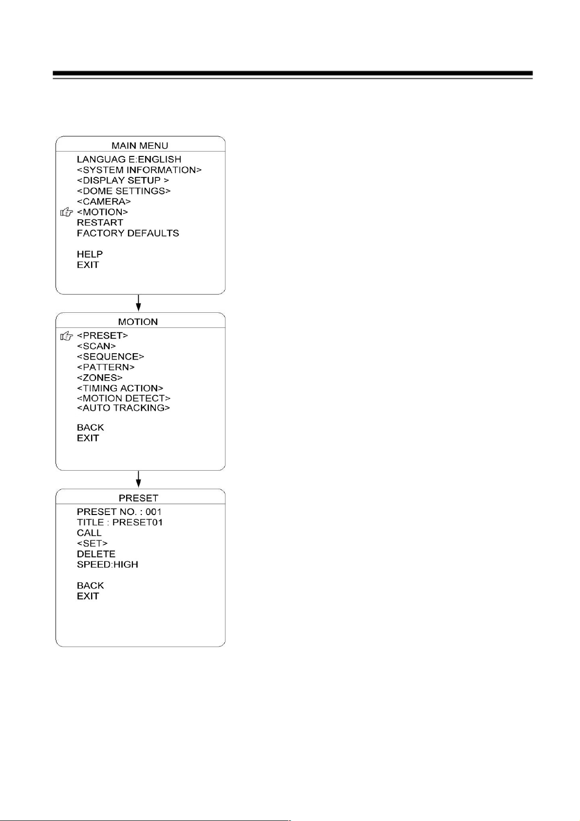
PRESET
The dome supports 220 presets. Please check the
following steps to set up a preset.
1) PRESET NO.: Move the cursor here and press
IRIS OPEN to enter the setup of Preset Number.
Move the joystick to select a preset number
(1-64 and 100-255) and press IRIS OPEN to
confirm.
2) TITLE: Move the cursor here and press IRIS
OPEN to enter the setup of Preset Title. Check
the detailed above in DOME TITLE settings.
3) <SET>: Move the cursor here and press IRIS
OPEN to enter. Move the dome to a defined
position as preset point and press IRIS OPEN
to save the preset position.
4) CALL: Move the cursor here and press IRIS
OPEN to call up the current preset.
5) DELETE: Move the cursor here and press
IRIS OPEN to delete the current preset.
6) SPEED: Move the cursor here and press IRIS
OPEN to set up the preset call up speed of
LOW, MID and HIGH.
78
Page 80

AUTO SCAN
The dome supports 8 groups of auto scan. Please
check the following steps to set up a scan.
1) SCAN NO.: Move the cursor here and press
IRIS OPEN to enter the setup of SCAN
Number. Move the joystick to select a preset
number (1-8) and press IRIS OPEN to confirm.
2) TITLE: Move the cursor here and press IRIS
OPEN to enter the setup of SCAN Title. Check
the detailed above in DOME TITLE settings.
3) <LEFT LIMIT>: Move the cursor here and
press IRIS OPEN to enter. Move the dome to a
defined position as left limit and press IRIS
OPEN to save this left boundary.
4) <RIGHT LIMIT>: Move the cursor here and
press IRIS OPEN to enter. Move the dome to a
defined position as right limit and press IRIS
OPEN to save this right boundary.
5) START: Move the cursor here and press IRIS
OPEN to start the current scan.
6) SCAN SPEED: Move the cursor here and
press IRIS OPEN to set up the scan speed
ranging 1-30.
79
Page 81

AUTO CRUISE (SEQUENCE)
The dome supports 8 groups of auto cruise and each
cruise supports 32 presets. . Please check the
following steps to set up cruise.
1) SEQ NO.: Move the cursor here and press IRIS
OPEN to enter the setup of Sequence Number.
Move the joystick to select a preset number (1-8)
and press IRIS OPEN to confirm.
2) TITLE: Move the cursor here and press IRIS
OPEN to enter the setup of Sequence Title. Check
the detailed above in DOME TITLE Settings.
3) <SEQUENCE SET>: Move the cursor here and
press IRIS OPEN to enter. Move the cursor to
EDIT and press IRIS OPEN enter edit mode of
sequence. Move the joystick left and right to
select each item.
a) When the < > is on the item NO., move
joystick up or down to select the Serial NO. of
the preset in a sequence. There are up to 32
presets in each sequence.
b) When the < > is on the item PRESET, move
the joystick up or down to select NO.
c) When the < > is on the INTERVAL, move the
joystick up or down to select the interval time.
d) When the < > is on the last item, move the
joystick up or down to select edition mode as
“INS (insert)”, “ok” and “delete”.
e) Press OPEN when selecting INS to insert the
settings into the position of current Serial No.
f) Press IRIS OPEN when selecting OK to
override the settings.Press IRIS OPEN when
selecting delete to delete the settings
4) DELETE/START: Move the cursor here and press
IRIS OPEN to delete/start the current sequence.
80
Page 82

PATTERN TOUR
The dome supports 4 pattern tours and each
pattern cover at most 10 Minutes of 500
commands. Please check the following steps to set
up a pattern.
1) PATTERN NO.: Move the cursor here and
press IRIS OPEN to enter the setup of Pattern
Number. Move the joystick to select a pattern
number (14) and press IRIS OPEN to confirm.
2) TITLE: Move the cursor here and press IRIS
OPEN to enter the setup of Pattern Title. Check
the detailed above in DOME TITLE settings.
3) <SET>: Move the cursor here and press IRIS
OPEN to enter. Move the dome up/down/left
right, make the zoom in/out and press IRIS
OPEN to save the pattern tour.
4) START: Move the cursor here and press IRIS
OPEN to start the current pattern tour.
5) DELETE: Move the cursor here and press
IRIS OPEN to delete the current pattern tour.
81
Page 83

ZONES
The use can set up zone title when the camera
moves to a defined location, which will make it
much easier for the user to identify the location.
The dome supports 8 zone titles. Please check the
following steps to set up a zone
1) ZONE NO.: Move the cursor here and press
IRIS OPEN to enter the setup of Zone Number.
Move the joystick to select a zone number (1-8)
and press IRIS OPEN to confirm.
2) TITLE: Move the cursor here and press IRIS
OPEN to enter the setup of Zone Title. Check
the detailed above in DOME TITLE settings.
3) <LEFT LIMIT>: Move the cursor here and
press IRIS OPEN to enter. Move the dome to a
defined position as left limit and press IRIS
OPEN to save this left boundary.
4) <RIGHT LIMIT>: Move the cursor here and
press IRIS OPEN to enter. Move the dome to a
defined position as right limit and press IRIS
OPEN to save this right boundary.
5) DELETE: Move the cursor here and press IRIS
OPEN to delete the current zone.
82
Page 84

TIMING ACTION
TIMING ACTION allows the user to set up the
actions of the dome in 7 days (each day with 8
timing segments). When fishing the setup, the
dome will do the actions according to the setup
motion during the defined time segment.
NO.: Here shows the day within a week. Move the
cursor here and press IRIS OPEN to enter. Move
joystick up or down to select the Serial No. (1-8)
and then press IRIS OPEN to confirm.
START: To set up the start time for the defined
motion within this time segment. Press IRIS
OPEN to confirm.
STOP: To set up the stop time for the defined
motion within this time segment. Press IRIS
OPEN to confirm.
MOTION: To setup the motion that will be
operated in this time segment. The motion
includes: NONE. PRESET 1-8, SCAN 1-4,
SEQUENCE 1-4 and PATTERN 1-4.
ON/OFF: Move the cursor here and press IRIS
OPEN to enter to enable or disable this function.
Press IRIS OPEN to confirm.
COPY: The user could set up each 8 segment of 7
days separately or can copy the finished setting for
one day to the current day. Move the cursor there
and press IRIS OPEN to copy the settings.
BACK: Press opeN to save and back to last menu.
It is not allowed to set up the same time
segment during one day. And the time
segment cannot exceed 00:00. During the timing
action segment, the defined action will be stopped
if the user moves the dome. If there is operation
during the defined time segment, the action will re-activated as long as it is in the
defined timing action segment.
83
Page 85

MOTION DETECT
The user can set up 8 motion detection scenes (each
scene with 4 detecting areas) under this menu. The
alarm output will be triggered when moving objects
enter these detecting areas
SCENE NO.: Move the cursor here and press IRIS
OPEN to enter the setup of Scene Number. Move the
joystick to select a preset number (1-8) and press IRIS
OPEN to confirm.
<EDIT SCENE>: Move the cursor here and press IRIS
OPEN to enter. Move the dome to a user-defined
detecting scene. Press IRIS OPEN to confirm.
<EDIT AREA>: Move the cursor here and press IRIS
OPEN to enter the menu of AREA EDIT.
a) AREA NO.: Move the cursor here and press
OPEN to enter the setup of AREA Number.
Move the joystick to select a preset number (1-4)
b) <AREA EDIT>: Move the cursor here and press
OPEN to enter the setup of AREA EDIT. The
screen will display frame with Serial No. The
user can move the frame to the top left Conner of
the wanted detecting area and press IRIS OPEN
to confirm. Then move the joystick to adjust the
size of detecting area and press OPEN to confirm
c) DELETE: Move the cursor here and press IRIS
OPEN to delete the current detecting area.
d) SENSITIVITY: Move the cursor here and press
OPEN to enter. Select among LOW. MID and
HIGH, press OPEN to confirm the sensitivity.
e) DELETE SCENE: Move the cursor here and
press IRIS OPEN to delete the current scene.
f) AUX ACTIVATE: The dome can activate the
alarm aux output when detecting the moving
object. Press IRIS OPEN to enter and select
between “ON” and “OFF” to activate or
deactivate this function.
g) CANCEL (SEC): Here means when the alarm aux output is activated by
84
Page 86

the detecting function, for how long it will last before the aux output will
be closed. The time ranging 1-60 Sec.
h) START: Move the cursor here and press IRIS OPEN to start
the function of motion detection.
85
Page 87

AUTO TRACKING (Optional)
Under the auto tracking mode, the dome will auto
track the moving objects entering the scene. When
the object is moving out of the scene, the dome will
return to a preset position as defined after the defined
time.
SENSITIVITY: The user can set up the auto
tracking sensitivity under this menu. When set as
LOW, the dome will do auto tracking when obvious
object entering the screen. When set as HIGH, the
dome will do auto tracking when small object
moving into the screen. Move the cursor there and
press the IRIS OPEN to enter.
TARGET: To set up the size of the tracking object.
The options include Large. MID and SMALL.
AUX: If set “ON” here, the object auto tracking will
activate alarm aux output at the same time. Press
IRIS OPEN to enter to select “ON” or “OFF”
ZOOM MATCH: Under the auto tracking model, if
turn on the function of ZOOM MATCH, the dome
will do zooming in and out during auto tracking to
keep the right proportion between the object and
background. Press the IRIS OPEN to enter. And
move the joystick to select the optical zoom.
ENABLE: Move the cursor here and press OPEN to
enter to select “ON” or “OFF” to enable or disable.
TRACKING SCENE SET: Here the user can set up
the scene that the dome will get back to when
finishing the action of auto tracking. Move the cursor
here and press IRIS OPEN to enter. Move the dome
to the wanted scene and press IRIS OPEN to confirm.
DELETE: Move the cursor here and press IRIS
OPEN to delete the return scene.
RETURN DELAY: To set up the time that dome will
waiting to return to this scene.
86
Page 88

RESTART
The dome allows the user to reset its settings
remotely under this menu.
Move the cursor here and press IRIS OPEN to
enter.
Select “OK” or “CANCEL” to continue the reset
or cancel the reset.
87
Page 89

FACTORY DEFAULTS
FACTORY DEFAULTS will allow the user to
recover all the setting to factory default setting.
Move the cursor here and press IRIS OPEN to
enter.
Select “OK” or “CANCEL” to continue the reset
or cancel the
reset.
88
Page 90

7. Troubleshooting
Before you send this IP Camera back to your dealer when you found this IP
Camera is not working properly, please checks the table as below to save
your time.
Problem
Possible solution(s)
Can’t
connect to
IP Camera
No IP
Camera
found
Check the IP address and port number is correct or not
Make sure the entry User name/Password is correct.
Make sure the port number is opened from the NVR and
Router.
Make sure the network cable is correctly connected to
your local area network. (The green LED will be flash).
Make sure the IP camera and NVR at the same LAN
segment.
Make sure the Switch Hub is workable.
Check the LAN cable and Ethernet port of NVR are
workable.
Check IP camera is powered.
Check the IP address and port number setting is matched
with IP camera.
NVR had been installed the correct video codec.
Make sure the network cable is correctly connected to
your local area network. (The green LED will be flash).
Make sure camera power is on.
Make sure the Switch Hub is workable.
Check the LAN cable and Ethernet port of NVR are
workable.
Check network routing cable(s).
Check cable distances do not exceed operating distance.
No image
If the place where IP camera is installed is too dark, try to
add some lights when possible.
Check if there’s anything covering the lens.
NVR had been installed the correct video codec.
89
 Loading...