

Page 1
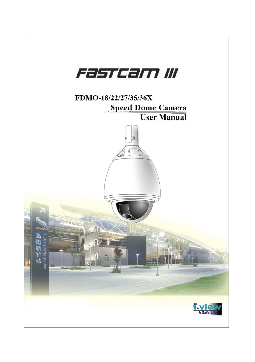
1
Version: 3.30
Doc. No: 2012092501
Page 2

2
FCC Statement
This equipment has been strictly tested and reached to Class A, pursuant to part 15 of the FCC
rules, which focus on providing reasonable protection against harmful exterior interference when
the equipment is operated in a commercial environment. While the equipment running, it
maybe cause a strong electromagnetic wave with constant frequency, which may interrupt the
radio communication if the user does not installed and used in accordance with the product user
manual.
Warning
Changes or modifications not expressly approved by the manufacturer could void the user’s
authority to operate the equipment.
This device may not cause harmful interference, and this device must accept any interference
received, including interference that may cause undesired operation.
Shielded cables and I/O cords must be used for this equipment to comply with relevant FCC
regulations.
Caution
Do NOT use power sources other than that specified.
Do NOT expose this appliance to rain or moisture.
Page 3

3
Table of Content
Table of Content
About This Guide ............................................................................................................... 4
Important Safeguards and Warning ................................................................................ 5
Chapter 1 Product Introduction ....................................................................................... 6
1-1. Product Package Content .................................................................................... 6
1-2. Product Overview ................................ ................................................................ 7
1-3. Product Features .................................................................................................. 8
Chapter 2 Installation ........................................................................................................ 9
2-1. Specification ................................ ................................................................ ........ 9
2-2. Outlet Cables Connections ................................................................................ 10
2-3. Baud Rate Setup ................................................................................................ 11
2-4. Camera Address Setup ...................................................................................... 11
2-5. Product with Ceiling Mount Installation ........................................................... 14
Chapter 3 Operation ........................................................................................................ 16
3-1. General Operation ............................................................................................. 16
3-2. Menu System ................................ ................................ ................................ ..... 18
Page 4

4
About This Guide
About This Guide
Conventions used in this guide
To make sure that you perform certain tasks properly, take note of the following symbols to use
throughout this manual.
WARNING: Information to prevent injury to yourself when trying to complete a task.
CAUTION: Information to prevent damage to the components when trying to complete a
task.
IMPORTANT: Information that you must follow to complete a task.
NOTE: Tips and additional information to aid in completing a task.
Page 5

5
Important Safeguards and Warning
Important Safeguards and Warning
It is not recommended to install this product by unqualified person.
The method and material of installation should be insured for the weight of the product
and enclosure as pan/tilt, camera lens, and so on
Stop using and power off the product if any unusual smell or smoke comes from the camera.
Do not install the camera in an intermittent lighting environment.
Do not aim the camera at the sun or any other strong light source
Do not install the camera where it might be exposed to rain or water.
Do not drop the camera or examine it in severe shocks or vibrations.
Do not touch the front glass of the camera with a dirty or coarse stuff.
Do not install the product under humid conditions, near flammable or explosive gases.
Page 6
6
Chapter 1: Product Introduction
Chapter 1 Product Introduction
Characterized as fast speed, high decision, low noise and long life, High-speed dome is being
popular more and more, it has being the best choice of retail, business, industry, government
and entertainment field depending on its good construction, convenient installation and widen range
of surveillance.
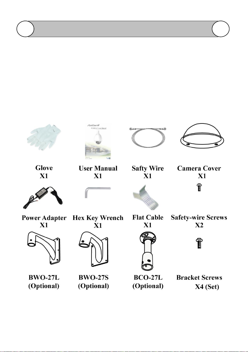
1-1. Product Package Content
Please check the package content by the following list.
Page 7
7
Chapter 1: Product Introduction
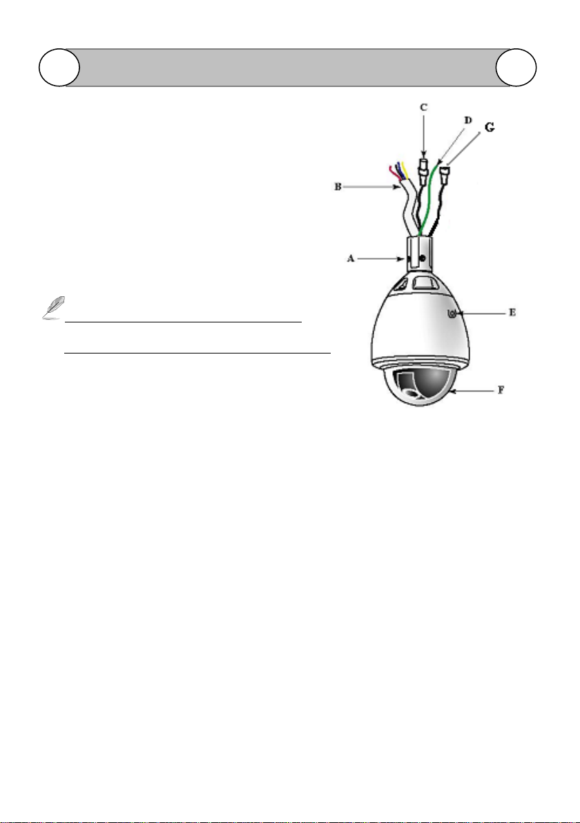
1-2. Product Overview
Parts Name Description
A. Screw holes for speed dome camera bracket
B. Speed dome power and RS485 connecting wires
Blue color: RS485 + (Rx +)
Yellow color: RS485 – (Rx -)
Black color: Revise
Red color: Revise
The Blue color wire RS485 + (Rx +) & Yellow
color wire RS485 – (Rx -) for Speed dome controller.
C. BNC video output connector
D. Surge protection cable (Yellow Color): Connect to the ground for surge protection
function.
E. Screw hole for Safety-wire connection.
F. Camera Cover
G. Power core with DC jack for DC 12V input.
Brown color: power DC 12V(+)
Blue color: power DC 12V (-)
Page 8

8
Chapter 2: Installation
1-3. Product Features
Optical Zoom: 36X (f = 3.4mm~122.4mm) optical zoom.
Day & Night: Switches from color mode to B/W mode automatically.
Weatherproof: IP66 and build in fan /heater for all weatherproof environmental structure.
Illumination: Super sensitivity of 0.05 lx (color mode) / 0.0015 lx (B/W mode).
Resolution: 540-TV line at color imaging horizontal resolution.
Masking: 24 Privacy zone masking enables users to veil unwanted zones.
Image Freeze: Hold last image during panning.
Image Stabilizer: Build in image stabilizer engine.
Protocol: Detect Pelco P and D protocol automatically.
Speed and Dwell Time: 5°~360 ° per second panning speed and dwell time can be selectable.
Home Position: Turn to home position when speed dome inactivate for a while.
Tour Group: Provide 8 programmable tour groups.
Pan/Tilt scan: 360˚ continuous pan, 90˚ in tilt and 180˚ in auto flip.
Preset: Max 128 programmable presets position.
Scanning: Three-dimensional scan between two presets.
OSD: Support On Screen Menu Display.
Remote Addressing: Support remote setup ID address function via RS-485.
Default Setup: Support restores function.
Proportional: Proportional controlling function.
Surge Protection: Inner mounts preventing from surge or lightning strike.
Power Protection: Auto protection when power plugs wrong power polarity.
Digital I/O: Provide 4 digital inputs and 1 relay output. (Optional).
Patrol-learn mode: Patrol-learn mode repetitive use for field application.
Page 9

9
Chapter 2: Installation
Item/Model
FDMO-36X
FDMO-35X
FDMO-22X
Image Sensor
1/4" SONY Ex-view CCD
1/3“ SONY EXview
HAD CCD II (Effio-E)
Optical Lens
36x (f= 3.4~122.4mm)
35x (f= 3.6~126mm)
22x (f=3.9~85.8mm)
Digital Zoom
16x
None
Resolution
530 TV lines
650 TV lines
650 TV lines
Video Output
1.0 Vp-p /75Ω (Composite)
S/N
52 dB (AGC Off)
52 dB (AGC Off)
52 dB (AGC Off)
Minimum
Illumination
1.4 Lux. (F1.6; IRE50)
0.5 Lux. (F1.6, Color)
0.01 Lux. (F1.6, B/W)
0.03Lux (F1.0/color)
0.01 Lux ( F1.0/B/W)
Day/Night
Auto /Color / B/W
BLC
Multi / Center / Off
Focus
Auto / One-push AF / Menu
AGC
Low / Normal / Middle / High / Off
White Balance
ATW / Menu / Push-look / Indoor / Outdoor / Florescent
Shutter Speed
NTSC: 1/60~1/10,000 second PAL: 1/50~1/10,000 second
Image Stabilizer
On / Off
None
Image Freeze
On / Off
None
Privacy Masking
24 Masked locations
None
Panning Speed
5°~360° / Second
Horizontal Scan
360 degree continuously
Vertical Scan
90 degree
Preset
128
Chapter 2 Installation
2-1. Specification
Page 10
10
Chapter 2: Installation
ID address
S/W: 256; DIP Switch: 64
Interface
RS-485; Half-Simplex
Baud Rate
1200 / 2400 / 4800 / 9600 BPS (Selectable)
Protocol
Pelco P and Pelco D auto detection
Housing
Aluminum
Mount Type
Wall / Ceiling (Optional)
Weatherproof
IP 66 / Build in Fan & Heater
Dimension
6 inches
Environmental
DC12V/3A
Dimension
-35℃~50℃
Weight
5 Kg
Cable Color
Function Description
Data
Note
Blue
For RS-485 control
RS485 + (Rx +)
Speed dome control.
Yellow
For RS-485 control
RS485 – (Rx -)
Power core
Power input
DC12V
Plug DC12V/3A
power supply
Black
BNC Video cable
Video
2-2. Outlet Cables Connections
Page 11
11
Chapter 2: Installation
Pin 7
Pin 8
1200/bps
OFF
OFF
2400/bps
ON
OFF
4800/bps
OFF
ON
9600/bps
ON
ON
ID (Pelco P)
Pin 1
Pin 2
Pin 3
Pin 4
Pin 5
Pin 6
0
ON
OFF
OFF
OFF
OFF
OFF
1
OFF
ON
OFF
OFF
OFF
OFF
2
ON
ON
OFF
OFF
OFF
OFF
3
OFF
OFF
ON
OFF
OFF
OFF 4 ON
OFF
ON
OFF
OFF
OFF
5
OFF
ON
ON
OFF
OFF
OFF
6
ON
ON
ON
OFF
OFF
OFF
7
OFF
OFF
OFF
ON
OFF
OFF
8
ON
OFF
OFF
ON
OFF
OFF
9
OFF
ON
OFF
ON
OFF
OFF
10
ON
ON
OFF
ON
OFF
OFF
ON
1 2 3 4 5 6 7 8
2-3. Baud Rate Setup
There is an 8-pins switch (Red one) on PCB as showing below:
Baud Rate (Pin 7 and 8 are the selectors for baud rate)
2-4. Camera Address Setup
Address List (Pin 1-6 address selectable)
Page 12

12
Chapter 2: Installation
11
OFF
OFF
ON
ON
OFF
OFF
12
ON
OFF
ON
ON
OFF
OFF
13
OFF
ON
ON
ON
OFF
OFF
14
ON
ON
ON
ON
OFF
OFF
15
OFF
OFF
OFF
OFF
ON
OFF
16
ON
OFF
OFF
OFF
ON
OFF
17
OFF
ON
OFF
OFF
ON
OFF
18
ON
ON
OFF
OFF
ON
OFF
19
OFF
OFF
ON
OFF
ON
OFF
20
ON
OFF
ON
OFF
ON
OFF
21
OFF
ON
ON
OFF
ON
OFF
22
ON
ON
ON
OFF
ON
OFF
23
OFF
OFF
OFF
ON
ON
OFF
24
ON
OFF
OFF
ON
ON
OFF
25
OFF
ON
OFF
ON
ON
OFF
26
ON
ON
OFF
ON
ON
OFF
27
OFF
OFF
ON
ON
ON
OFF
28
ON
OFF
ON
ON
ON
OFF
29
OFF
ON
ON
ON
ON
OFF
30
ON
ON
ON
ON
ON
OFF
31
OFF
OFF
OFF
OFF
OFF
ON
32
ON
OFF
OFF
OFF
OFF
ON
33
OFF
ON
OFF
OFF
OFF
ON
34
ON
ON
OFF
OFF
OFF
ON
35
OFF
OFF
ON
OFF
OFF
ON
36
ON
OFF
ON
OFF
OFF
ON
37
OFF
ON
ON
OFF
OFF
ON
38
ON
ON
ON
OFF
OFF
ON
39
OFF
OFF
OFF
ON
OFF
ON
40
ON
OFF
OFF
ON
OFF
ON
41
OFF
ON
OFF
ON
OFF
ON
42
ON
ON
OFF
ON
OFF
ON
43
OFF
OFF
ON
ON
OFF
ON
Page 13

13
Chapter 2: Installation
44
ON
OFF
ON
ON
OFF
ON
45
OFF
ON
ON
ON
OFF
ON
46
ON
ON
ON
ON
OFF
ON
47
OFF
OFF
OFF
OFF
ON
ON
48
ON
OFF
OFF
OFF
ON
ON
49
OFF
ON
OFF
OFF
ON
ON
50
ON
ON
OFF
OFF
ON
ON
51
OFF
OFF
ON
OFF
ON
ON
52
ON
OFF
ON
OFF
ON
ON
53
OFF
ON
ON
OFF
ON
ON
54
ON
ON
ON
OFF
ON
ON
55
OFF
OFF
OFF
ON
ON
ON
56
ON
OFF
OFF
ON
ON
ON
57
OFF
ON
OFF
ON
ON
ON
58
ON
ON
OFF
ON
ON
ON
59
OFF
OFF
ON
ON
ON
ON
60
ON
OFF
ON
ON
ON
ON
61
OFF
ON
ON
ON
ON
ON
62
ON
ON
ON
ON
ON
ON
Page 14
14
Chapter 2: Installation
2-5. Product with Ceiling Mount Installation
2-5-1. Ceiling Mount Model: BCO-27L
BCO-27L Dimension
Installation Procedure:
Please follow the steps below to install the BCO-27L and speed dome.
Step 1: Tear off the anti-shake tap and cover from the camera lens.
Step 2: Remove the camera cover inner protection stuff, and install the camera
cover with the speed dome by tightening up the screws.
Step 3: Organize the required cables from the ceiling, and run through the
cables to the BCO-27L pipe.
Step 4: Install the BCO-27L with ceiling by the screws, and make sure the
BWC-27L is firm enough with the ceiling.
Step 5: Install the Safety-wire with BCO-27L and speed dome by the screws.
Step 6: Connect all the required cables from BCO27L and speed dome.
Step 7: Install the speed dome with BCO-27L by tightening up the screws.
Step 8: remove the camera cover protection plastics.
Page 15

15
Chapter 3: Operation
2-6-1. Wall Mount Model: BWO-27S
2-6-2.1 BWO-27S Dimension
2-6-2.2 Installation Procedure:
Please follow the steps below to install the BWO-27S and speed dome.
Step 1: Tear off the anti-shake tap and cover from the camera lens.
Step 2: Remove the camera cover inner protection stuff, and install the
camera cover with the speed dome by tightening up the screws.
Step 3: Organize the required cables from the ceiling through
the cables
to the BWO-27S pipe.
Step 4: Install the BWO-27S with ceiling by the screws, and make sure
the BWO-27S is firm enough with the ceiling.
Step 5: Install the Safety-wire with BWO-27S and speed dome by the
screws.
Step 6: Connect all the required cables from BWO-27S and speed
dome.
Step 7: Install the speed dome with BWO-27S by tightening up the screws.
Step 8: remove the camera cover protection plastics.
Page 16

16
Chapter 3: Operation
Function
Description
Enter/Exit On Screen
Menu
Press [Menu] button, “95 + [Preset] button” to enter OSD menu.
Press [Menu] button again to exit the OSD menu.
Start Auto Scan
Press [Scan] button or “99 + [Call] button”.
Start Auto Pattern
Press [Pattern] button or “100 + [Call] button”.
Start Auto Tour Group
Press [Tour] button, or press “76 + [Call] button” to start auto Tour
#1; “77 + [Call] button” to start auto Tour #2; …. “83 + [Call]
button” to start auto Tour #8
Stop Scan/Tour/Pattern
running
Press [Scan]/[Tour]/[Pattern] button again; “96+ [Call] button” to
stop Scan/ Tour/ Pattern running.
Reboot Dome power
Press “101 + [Call] button”.
Reboot camera power
Press “102 + [Call] button”. (For SONY camera module only)
Home position
Press “76 + [Preset] button”.
Auxiliary
Press [Aux 1] button to enable “ Heater “ or “ Heater & Fan “ or
“ Alarm output “; press [Aux 1] button again to stop the function .
Setup preset
Press “Number Key + [Preset] button” to setup the preset position.
Call preset
Press “Number Key + [Call] button” to view preset position.
Zoom in
Press [Tele] button, or turn the joystick clockwise until the
desired view occurs or limitation reached.
Zoom out
Press [Wide] button, or turn the joystick anticlockwise until the
desired view occurs or limitation reached.
Chapter 3 Operation
3-1. General Operation
3-1-1. Camera Basic Control Function
FastCam III offer basic function control by enter numbers on keyboard, for easy and fast command.
Page 17

17
Chapter 3: Operation
Focus Far
Select Auto/Manual in the menu. (Refer to Menu Edit Manual)
Under the Manual mode, please press [FAR] button till the view
is clearly. The manual control will be invalid under the Auto mode.
Focus Near
Select Auto/Manual in the menu. (Refer to Menu Edit Manual).
Under the Manual mode, please press [FAR] button till the view
is clearly. The manual control will be invalid under the Auto mode.
Preset
Max 128 presets (Refer to Controlling System Manual)
Privacy zone asking
Can program max 24 units zone in current vision to protect privacy,
and store in presets. This function is in regard to the
selected camera. (For FDMO-36X Only)
Preset Title
Refer to description of Menu Edit Manual
Camera Title
Refer to description of Menu Edit Manual
Proportional
Curve character
The manual control to the pan and tilt will be limited speed when
proportion is on. (Refer to description of Menu Edit).
Page 18

18
Chapter 3: Operation
SYSTEM INFO
FASTCAM III
VERSION:3.30
BAUD RATE:9600 BPS
PROTOCOL:PELCO-D/P
CAMERA BRAND:Auto
DIP ADDRESS: 001
S/W ADDRESS: 000
Test Ending
3-1-2. OSD Display when power on
When power on, the protocol and address will be displayed on
the screen. After the dome accepts the correct commands, the
information will disappear. E.g. : The screen displays as
following information. The information is as the protocol,
Firmware version, ID Address and Baud rate which have been
setup. Please refer to the right side window screen.
3-2. Menu System
3-2-1. Menu Operation
User can call out OSD menu by entering “ 95+[CALL]” on
keyboard or Press [MENU] button of the controller to enter
the Main Menu.
1.) The item with “→“ are the highlight menu.
2.) Move the joystick right/left/up/down direction to change selection. Press [OPEN] button
to change the parameters.
3.) In the item submenu, lean to right direction of joystick or press [OPEN] button to confirm
the changing. After confirmation, the parameters of current item will be changed.
4.) <BACK> is available in all menu pages. To go back to previous page, move icon “→” to
<BACK> and lean right to confirm. Or press [CLOSE] button on keyboard to go back.
5.) Select <EXIT>, and then press [OPEN] button (lean to right direction of joystick), the menu
will be closed, and the dome exits the OSD programming menu.
Page 19

19
Chapter 3: Operation
SETUP MENU
→SYSTEM SETUP
DISPLAY SETUP
PARAMETER SETUP
RECOVERY SETUP
OTHERS SETUP
EXECUTION MENU
EXIT
SETUP MENU
SYSTEM SETUP
DISPLAY SETUP
PARAMETER SETUP
RECOVERY SETUP
OTHERS SETUP
EXECUTION MENU
EXIT
SYSTEM SETUP
VERSION: 3.30
BAUD RATE: 9600 BPS
PROTOCOL: PELCO-D/P
CAMERA BRAND:SONY
DIP ADDRESS: 001
S/W ADDRESS: 001~
255<ENABLE>
BACK
3-2-2. Menu Function Description
[MAIN MENU]
Via the controller, Setup Preset 95 or Press [MENU] button to enter the main menu. The main menu
is including System setup, Display setup, Parameter setup, Recover setup, others setup, Execution
menu and Exit.
The initialization of speed dome can be read in System
Information, which is including Firmware version,
Baud Rate, Camera brand, Protocol, Hardware or Software
Address.
A. [SYSTEM SETUP]
Page 20

20
Chapter 3: Operation
S/W ADDRESS:
a.) Select <SYSTEM SETUP> in main menu
b.) Press [OPEN] button or lean to right direction of joystick to enter SYSTEM SETUP menu.
c.) Move the joystick down to S/W ADDRESS and then press [OPEN] button or lean to right
direction of joystick to enable the setup ID address by S/W ADDRESS. When the S/W
ADDRESS function is enabled; the DIP ADDRESS will be disabling automatically.
d.) Move the joystick up or down to select ID address from 0~255. If the S/W ADDRESS
enable, the function of DIP address function will automatically closed. The ID address
SETUP must via the S/W ADDRESS.
e.) Select <BACK> or <EXIT>. Press [OPEN] button to return to main menu or exit
programming menu.
f.) To change back by DIP ADDRESS order => Set S/W ADDRESS to “ - - - “. DIP
ADDRESS will automatically set as default.
S/W ADDRESS can be only set up to 63 when you want to change the S/W ADDRESS to
DIP ADDRESS, because DIP ADDRESS can be no more then 63, if S/W ADDRESS is
more then 63, there will be no response of the camera.
Page 21

21
Chapter 3: Operation
DISPLAY SETUP
CAMERA ID:ON/OFF
PRESET:ON/OFF
PAN/TILT ANGLE:ON/OFF
TEMPERATURE:ON/OFF
CAMERA OSD:ON/OFF
BACK
EXIT
SETUP MENU
SYSTEM SETUP
DISPLAY SETUP
PARAMETER SETUP
RECOVERY SETUP
OTHERS SETUP
EXECUTION MENU
EXIT
B. [DISPLAY SETUP]
Set information by the user what to show on the screen when user does the correlative operation.
<CAMERA ID: OFF/ON>
ON: Display camera ID address on the screen.
OFF: Disable the camera ID address from screen.
<PRESET: OFF/ON>
ON: Display the preset position number on the screen.
OFF: Disable the preset position number on the screen.
<PAN/TILT ANGLE: OFF/ON>
ON: Display camera moving angle on the screen.
OFF: Disable camera moving angle on the screen.
<TEMPERATURE: OFF/ON>
ON: Display the temperature of speed dome on the screen.
OFF: Disable the temperature of speed dome from screen.
<CAMERA OSD: OFF/ON>
ON: Display camera OSD information screen.
OFF: Disable camera OSD information from screen.
Page 22

22
Chapter 3: Operation
PARAMETER SETUP
CAMERA SETUP
MOTION SETUP
TITLE EDIT
TOUR EDIT
SCAN EDIT
PATTERN EDIT
MASK EDIT
POWER ON:SCAN
BACK
EXIT
SETUP MENU
SYSTEM SETUP
DISPLAY SETUP
PARAMETER SETUP
RECOVERY SETUP
OTHERS SETUP
EXECUTION MENU
EXIT
CAMERA SETUP 1/2
FOCUS:AUTO/MANUAL
DIGITAL ZOOM: ON/OFF
WB: AUTO/ATW
BLC: ON/OFF
DAY/NIGHT: AUTO/OFF
ZOOM SPEED: FAST/SLOW/NORMAL
CAPTURE:ON/OFF
NEXT PAGE
BACK
EXIT
CAMERA SETUP
CAMERA SETUP
MOTION SETUP
TITLE EDIT
TOUR EDIT
SCAN EDIT
PATTERN EDIT
MASK EDIT
POWER ON:SCAN
BACK
EXIT
C. [PARAMETER SETUP]
It is used to setup the functions and parameters of the dome. It includes 7 sub-menus: Motion Setup,
Title Edit, Tour Edit, Scan Edit, Pattern Edit, Mask Edit, Power On etc..
1. <CAMERA SETUP>
Page 23

23
Chapter 3: Operation
User may change settings of Camera
<CAMERA SETUP>
<FOCUS: AUTO/MANUAL >
AUTO: Camera will automatically adjust focus.
MANUAL: User manually adjusts focus.
<DIGITAL ZOOM: ON/OFF >
ON: Enable digital zoom.
OFF: Disable digital zoom.
<WB: ON/OFF>
ON: Enable White Balance.
OFF: Disable White Balance.
< BLC: OFF/ON>
ON: Enable Back Light Compensation.
OFF: Disable Back Light Compensation.
< DAY/NIGHT: AUTO/OFF>
AUTO: Automatically switch day/night mode.
OFF: Turn off day/night mode.
<ZOOM SPEED: FAST/SLOW/NORMAL>
FAST: Set zoom speed to fast.
SLOW: Set zoom speed to slow.
NORMAL: Set zoom speed to normal.
< CAPTURE: ON/OFF>
This feature freezes the scene on the monitor when going to a preset. This allows for smooth
transition from one preset scene to another.
ON: The image on the screen freezes when a preset is called. When the dome reaches the
preset, the image is unfrozen and the preset scene is displayed.
Page 24

24
Chapter 3: Operation
CAMERA SETUP 2/2
MIRROR: ON/OFF
FLIP: ON/OFF
LOW SHUTTER: ON/OFF
AE MODE: IRIS/AE
NR: ON/OFF
PRESET MODE: TRACE/NO TRACE
CAMERA MENU
PRE PAGE
BACK
EXIT
CAMERA SETUP
CAMERA SETUP
MOTION SETUP
TITLE EDIT
TOUR EDIT
SCAN EDIT
PATTERN EDIT
MASK EDIT
POWER ON:SCAN
BACK
EXIT
OFF: The image is never frozen.
<CAMERA SETUP>
<CAMERA SETUP >
< MIRROR: OFF/ON>
ON: Enable video mirror reflection.
OFF: Disable video mirror reflection.
< FLIP: ON/OFF>
ON: Enable screen flip mode
OFF: Disable screen flip mode
< AE MODE: IRIS/AE>
IRIS: Set camera to IRIS Mode
AE: Set camera to AE (Auto Exposure) mode.
< NR: ON/OFF>
Page 25

25
Chapter 3: Operation
ON: Enable NR (Noise Reduction) function.
OFF: Disable NR (Noise Reduction) function.
< PRESET MODE: TRACE/NO TRACE> * this function is optional.
ON: Enable Auto Trace Object function
OFF: Disable Auto Trace Object function.
CAMERA SETUP page is only for Sony camera module, other modules may not be available.
Page 26

26
Chapter 3: Operation
MOTION SETUP
AUTO FLIP: ON/OFF
PROPORTION: ON/OFF
ACTIVATION: ON/OFF
HOME POSITION: ON/OFF
MANUAL SPEED: 005~360
SCAN SPEED: 01~90
TOUR SPEED: 005~360
DWELL TIME: 001~020
HOME TIME: 01MIN~60MIN
BACK
EXIT
CAMERA SETUP
CAMERA SETUP
MOTION SETUP
TITLE EDIT
TOUR EDIT
SCAN EDIT
PATTERN EDIT
MASK EDIT
POWER ON:SCAN
BACK
EXIT
2. <MOTION SETUP>
<AUTO FLIP: ON/OFF>
When the camera tilts downward and goes just beyond the vertical position, the dome rotates
180 degrees. When the dome rotates (flips), the camera starts moving upward as long as
you continue to hold the joystick in the down position. Once you let go of the joystick after
the dome rotates, joystick control returns to normal operation.
ON: Enable automatically flip.
OFF: Disable automatically flip.
<PROPORTION: ON/OFF>
Proportional pan automatically reduces or increases the pan and tilt speeds in proportion to
the amount of zoom. At telephoto zoom settings, the pan and tilt speeds will be slower for a
given amount of joystick deflection than at wide zoom settings. This keeps the image from
moving too fast on the monitor when there is a large amount of zoom.
Page 27

27
Chapter 3: Operation
ON: Enable Proportion.
OFF: Disable Proportion.
<ACTIVATION: ON/OFF>
When dome is running tour/scan mode, if joystick is operate once, the program will be
hold and resume later on. But if joystick is operate more than once the program will
be cenacle itself.
ON: Enable Activation.
OFF: Disable Activation.
<HOME POSITION: ON/OFF>
When FastCam III is in idol of amount of time (user can define how many minutes),
the camera will return to home position.
ON: Enable home position.
OFF: Disable home position.
<MANUAL SPEED: 5~360 >
Manual Speed allows the user to define how fast the dome will rotate. By leaning left to
decrease or leaning right to increase the speed. User may set up to 360 degree of the fastest,
or else the number will cycle again to the slowest 5 degree.
<SCAN SPEED: 1~90 >
Scan speed is the degrees per second that the dome will pan when in a scan mode. Scan
speed is adjustable from 1 to 90 degrees per second through the programming menu. By
leaning left to decrease or leaning right to increase the speed. User may set up to 90 degree of
the fastest, or else the number will cycle again to the slowest 1 degree.
<TOUR SPEED: 5~360 >
User may define the speed of Tour Mode, the numbers are represent moving degrees, by
leaning left to decrease or leaning right to increase the speed. User may set up to 360 degree
of the fastest, or else the number will cycle again to the slowest 5 degree.
Page 28

28
Chapter 3: Operation
<DWELL TIME: 1~20>
Dwell time is when dome running tour mode, how many seconds should dome stay at in
between the stops.
<HOME TIME: 1mins~ 60mins>
To set home position “Press 76 + [Preset] button”.
When camera is in idol, user can define how many minutes will camera return to home
position.
Page 29

29
Chapter 3: Operation
TITLE EDIT
PRESET/CAM: CAMERA/PRE001~128
TITLE EDIT:
BACK
EXIT
DISPLAY:
CAM001
CAMERA SETUP
CAMERA SETUP
MOTION SETUP
TITLE EDIT
TOUR EDIT
SCAN EDIT
PATTERN EDIT
MASK EDIT
POWER ON:SCAN
BACK
EXIT
3. <TITLE EDIT>
<PRESET/CAM: CAMERA/PRE001~008>
To edit each label, select the label to edit, lean down joystick to <TITLE EDIT>.
<TITLE EDIT:>
The Camera and Preset Position can be marked separately. For each label, max 16 characters can
be edited, including the space.
The edit label will be showing on the bottom, below the label “ I ” means which character will be
edit, move the joystick to highlight “ I “, once the “ I “ is flashing lean left or right to
the character wish to edit, then move joystick to the top to select what character to replace/add. To
add a space in between characters, move joystick to let “ SPACE “ flashing and lean right to add.
Same instruction as “ RESET “.
Page 30

30
Chapter 3: Operation
TOUR EDIT
TOUR →01 RELOAD CLEAR
SET UP PRESET
01 001 09 009
02 002 10 010
03 003 11 011
04 004 12 012
05 005 13 013
06 006 14 014
07 007 15 015
08 008 16 016
NEXT PREVIOUS BACK EXIT
CAMERA SETUP
CAMERA SETUP
MOTION SETUP
TITLE EDIT
TOUR EDIT
SCAN EDIT
PATTERN EDIT
MASK EDIT
POWER ON:SCAN
BACK
EXIT
4. <TOUR EDIT>
<TOUR EDIT>
User can program dome when running <TOUR MODE>, each dome can program up to 128
presets. To program, go to <TOUR EDIT> page,
TOUR 01 – 08
In tour edit mode, there is total 8 different pages, each page has 16 slots to edit.
RELOAD
User may reset default settings.
CLEAR
User can clean all slots memory.
01 – 16 (17- 32/ 33- 48 …..)
In different number of slots, user can program which preset should dome run by orders
Page 31

31
Chapter 3: Operation
SCAN EDIT
SCAN MODE: 360/A←B/A→B
POSITION A:
PRE001~128/NO
USE
POSITION B:
PRE001~128/NO
USE
CAMERA SETUP
CAMERA SETUP
MOTION SETUP
TITLE EDIT
TOUR EDIT
SCAN EDIT
PATTERN EDIT
MASK EDIT
POWER ON:SCAN
BACK
EXIT
5. <SCAN EDIT>
<SCAN EDIT>
User can program dome when running <SCAN MODE>, each dome 3 different scan modes.
To program, go to <SCAN EDIT> page,
<SCAN MODE>
360 : Dome will keep rotating 360∘
A←B : Dome will keep repeating from position B to position A
A→B : Dome will keep repeating from position A to position B
<POSITION A>
User can set which preset as position A
<POSITION B>
User can set which preset a position B
Page 32

32
Chapter 3: Operation
PATTERN EDIT
→ RECODE
RUN
BACK
EXIT
CAMERA SETUP
CAMERA SETUP
MOTION SETUP
TITLE EDIT
TOUR EDIT
SCAN EDIT
PATTERN EDIT
MASK EDIT
POWER ON:SCAN
BACK
EXIT
6. <PATTERN EDIT>
<PATTERN EDIT>
A pattern is a memorized, repeating, series of pan, tilt, zoom and preset functions that can be
recalled with a command from a controller or automatically by a programmed function.
RECORD
User can record pattern for the dome, <OPEN> to start recording, when start recording, use
joystick to move the viewing position as the pattern record, when finish select <CLOSE> to
end recording, <CLOSE> again to exit.
RUN
Dome will run the pattern which you have been recorded.
Page 33

33
Chapter 3: Operation
MASK EDIT
ZONE: 001~024
EDIT:
DISPLAY: ON/OFF
BACK
EXIT
CAMERA SETUP
CAMERA SETUP
MOTION SETUP
TITLE EDIT
TOUR EDIT
SCAN EDIT
PATTERN EDIT
MASK EDIT
POWER ON:SCAN
BACK
EXIT
7. <MASK EDIT>
1. <PARAMETER SETUP>
2. <POWER ON>
<MASK EDIT>
Mask edit allows a user to program up to 24, user-defined areas that cannot be viewed by the
operator of the dome system. A mask area will move with pan and tilt functions
and automatically adjust in size as the lens zooms telephoto and wide.
Page 34

34
Chapter 3: Operation
POWER
POWER ON
PRE01/08
SCAN
TOUR01/08
PATTERN
CAMERA SETUP
CAMERA SETUP
MOTION SETUP
TITLE EDIT
TOUR EDIT
SCAN EDIT
PATTERN EDIT
MASK EDIT
POWER ON:SCAN
BACK
EXIT
8. <POWER ON>
<POWER ON: POWER ON/PRE01~08/SCAN/TOUR01~08/PATTERN>
When dome is power on, user can program which dome will start up from.
POWER ON
Dome will just power on, remain position.
PRE01~08
Dome will power on at which preset position.
SCAN
Dome will power on with Scan Mode
TOUR01~08
Dome will power on with Tour Mode.
PATTERN
Dome will power on with Pattern Mode.
Page 35

35
Chapter 3: Operation
RECOVERY SETUP
DELETE PRESETS OK
DEFAULT SETTING
RESET CAMERA
REBOOT DOME
BACK
EXIT
SETUP MENU
SYSTEM SETUP
DISPLAY SETUP
PARAMETER SETUP
RECOVERY SETUP
OTHERS SETUP
EXECUTION MENU
EXIT
D. <RECOVERY SETUP>
<RECOVERY SETUP>
DELETE PRESETS
Delete all the presets
DEFAULT SETTINGS
Restore all settings to default of Speed Dome.
RESET CAMERA
Use this function to reset all settings of camera module to factory default.
REBOOT DOME
Reboot the system if it is not operating or if there is no control. Rebooting the system
will cycle dome and camera power without changing programmed dome settings.
Page 36

36
Chapter 3: Operation
OTHERS
ALARM SET
PASSWORD SETUP
TV SYSTEM: NTSC/PAL
TEMPERATURE: AUTO/MANUAL
CAMERA BRAND:AUTO
BACK
EXIT
SETUP MENU
SYSTEM SETUP
DISPLAY SETUP
PARAMETER SETUP
RECOVERY SETUP
OTHERS SETUP
EXECUTION MENU
EXIT
ALARM SETUP
→ALARM1 TYPE:N.O./N.C.
ALARM2 TYPE:N.O./N.C.
ALARM3 TYPE:N.O./N.C.
ALARM4 TYPE:N.O./N.C.
ALARM1 ACT: REVISE/PRE001-128
ALARM2 ACT: REVISE/PRE001-128
ALARM3 ACT: REVISE/PRE001-128
ALARM4 ACT: REVISE/PRE001-128
ALARM OUTPUT: CONTINUE
BACK
EXIT
OTHERS
ALARM SETUP
PASSWORD SETUP
TV SYSTEM: NTSC
TEMPERATURE: AUTO
CAMERA BRAND: AUTO
BACK
EXIT
E. <OTHERS SETUP>
1. <ALARM SETUP>
Page 37

37
Chapter 3: Operation
PASSWORD SETUP
→PASSWORD: DISABLE/ENABLE
PASSWORD: -----------CONFIRM :-------------BACK
EXIT
<CALL1 . . . 9>EQ<1 . . . 9>
OTHERS
ALARM SETUP
PASSWORD SETUP
TV SYSTEM: NTSC
TEMPERATURE: AUTO
CAMERA BRAND: AUTO
BACK
EXIT
<ALARM SETUP>
FastCam III has four alarm inputs, which can be programmed as N.C. or N.O. When
an alarm signal is received, it can triggers the user-defined action ALARM ACT
(revise, pre001~128) and ALARM OUTPUT can be define as DISABLE,
CONTINUE, 60 SECONDs.
Disable
When alarms triggers, no action will be responds.
Continue
When alarms triggers, FastCam III will keep sending out a signal, till operator turn
off
60 seconds
When alarms triggers, FastCam III will send out signal for 60 seconds.
2. <PASSWORD SETUP>
PASSWORD SETUP
FastCam III features password protection to prevent unauthorized changes to the dome
settings. An operator can open the System Information and Display Setup Screens, but cannot
Page 38

38
Chapter 3: Operation
access any of the Dome settings menus when the password setting is enabled.
To set up password, move joystick to highlight PASSWORD press the number you wish to
enter then press [CALL], example (1 + [CALL] as 1, 2+[CALL] as 2). User may only enter
six digitals. Enter again in CONFIRM line to confirm, when it’s confirmed, OK will be
shown.
3. <TV SYSTEM: NTSC / PAL>
Select the correct TV system for your area application. Otherwise the OSD display has
problem sometime.
4. <TEMPERATURE: Auto / Manual>
Auto : If user define Temperature as Auto mode, when FastCam III detect the temperature
is 5℃, FastCam III will turn on heater, and when it detect 45℃, FastCam III will turn on fan
automatically.
Manual: If user defines Temperature as Manual, the heater or fan will be controlled by
manually.
5. <CAMERA BRAND: Auto / Sony / Hitachi / LG / LGMT / CNB>
The FastCam II Dome suits for many brands camera module such as Sony、Hitachi、LG、
LGMT and CNB. The “Auto mode” suits for all types camera modules.
Page 39

39
Chapter 3: Operation
EXECUTION MENU
→ RUN TOUR: 01-08
RUN SCAN
RUN PATTERN
AUX:FAN/HEAT/ALARM
SETUP MENU
EXIT
SETUP MENU
SYSTEM SETUP
DISPLAY SETUP
PARAMETER SETUP
RECOVERY SETUP
OTHERS SETUP
EXECUTION MENU
EXIT
F. [EXECUTION MENU]
EXCUTION MENU
RUN TOUR 01~08
User can define which tour mode should run when press [TOUR] on keyboard
RUN SCAN
Operate Scan Mode when user selected
RUN PATTERN
Operate Pattern Mode when user selected
AUX: FAN/HEAT/ALARM
User can manually operate AUX function for field application, for example User may
turn on turn on heater & fan to dry way vapor steam of camera’s cover. Fast Cam
III can also send out ALARM signal to trigger add on equipment such as lighting or
beeper.
Temperate Mode is under OTHER sub menu, In order to operate AUX, Temperate Mode must
set to Manual, otherwise AUX function will not operate.
Page 40

40
Chapter 4: Troubleshooting
Problems
Possible Causes
Remedies
No action and images
when power on
Power supply damaged or
insufficient power
Replace
Wrong connection of power
supply
Correct
Faults in
engineering circuits
Remove
Abnormal self-inspection.
Images with roaring
sound of the motor
Mechanical fault
Repair
Tilting camera
Place uprightly
Insufficient electrical power
Replace with
qualified power supply
Normal self-inspection but
no images
Failed Video Flat cable
Replace
Camera damaged
Replace
Successful self-inspection
but out of control
Wrong connection of
RS-485 signal wire
Correct
Mismatched address of
spherical camera
Reselect
Problem on PTZ controller
Replace
Too longer distance
of communication
Correct
 Loading...