

Page 1
Version: V1.0
Doc. No.:
ec-5miP Box Network camera
5-megaPixels Network camera
User meNU
1020321001
Page 2

Safety information
This symbol indicates that dangerous voltage consisting a risk of electric shock is
present within th is u nit.
This exclamation point symbol is intended to alert the user to the presence of important
operating and maintenance (servicing) instructions in the lite rature accompanying th e
appliance.
WARNING
To prevent damage that may result in fire or electric shock hazard, do not expose this
appliance to rain or moisture.
To prevent injury, this apparatus must be securely attached to the floor / wall in accordance
with the installation instructions.
WARNING
1. Be sure to use only the standard adapter that is specified in the specification sheet using any
other adapter could cause fire, electric shock, or damage to the product.
2. Incorrectly connecting the power supply or replacing battery may cause explosion, fire,
electric sho ck, o r dam age t o the product.
3. Do not connect multiple cameras to a single adapter. Exceeding the capacity may cause
the abnormal heat generation or fire.
4. Securely plug the power cord into the power receptacle, insecure connec tion may c au s e fire.
5. When installing the cam era, fasten it securely and firmly. The f all of camera may cause
personal injury.
2
Page 3

6. Do not place conductive objects (e.g. screwdrivers, coins, metal parts, etc.) or containers
filled with water on top of th e cam era. Doing so may cause personal injury due to fire,
electric shock, or falling objects.
7. If any unusu al sm ells or sm oke come f rom the unit, stop using the product. In such case,
immediately d is conn ect th e p ow er sou rc e an d con ta ct the se rvi ce cen t er. Continued use in
such a condition may cause fire or electric shock.
8. If this product fails to operate normally, contact the nearest service center and never
disassemble or modify this product in any way. (I-View is not liable for problems caused by
unauthorized modifications or attempted repair.)
9. When cleaning, do not spray water directly onto parts of the product. Doing so may cause
fire or electric shock.
CAUTION
Do not drop objects on the product or apply strong shock to i t. Keep aw ay from a loc ati on
subject to excessive vibration or magnetic interference.
Do not install in a location subject to high temperature (over 50°C), low temperature (below
-10°C), or high humidity. Doing so may cause fire or electric shock.
If you want to relocate the already installed product, be sure to turn off the power and then
move or reinstall it.
Remove the power plug from the ou tle t when th en th ere is a lig htning . Neglecting to do so
may cause fire or damage to the product.
Keep out of direct sunlight and heat radiation sources. It may cause fire.
Install it in a place with good ventilation.
Avoid aiming the camera directly towards extremely bright objects such as sun, as this may
damage the CCD image sensor.
Apparatus shall not be exposed to dripping or splashing and no objects filled with liquids ,
such as v ases, sha ll be placed on the apparatus.
The Mains plug is used as a disconnect device and shall stay readily operable at any time.
Do not expose the camera to radioactivity. Radioactivity exposure may damage the CCD.
3
Page 4

IMPORTANT SAFETY INSTRUCTIONS
Read these instructions.
Keep these instructions.
Heed all warnings.
Follow all instructions.
Do not use this apparatus near water .
Clean only with dry cloth .
Do not block any ventilation openings. Install in accordance with the manufacturer’s
instructions.
Do not ins tall near any heat sources su ch as radi ators, h e at registe rs, or other app ar a t us
(Including amplifiers) that produce heat.
Do not defeat the safety purpose of the polarized or grounding-type plug. A polarized plug
has two blades with one wider than the other. A grounding type plug has two blades and a
third grounding prong. The wide bl a de or th e third prong is provided for your safety. If the
provided plug does not fit into your outlet, consult an electrician for replacement of the
obsolete outlet .
Protect the power cord from being walked on or pinched particularly at plugs, convenience
receptacl es, and the point where they exit from the a p p ar atus.
Only use attachm en ts/access o ries speci fied by the manufacturer.
Use only w ith cart, stan d, t ri pod, bracket, or table specified by the
manufacturer, or sold with the apparatus.
Unplug this apparatus when a card is us ed. Use caution when moving the cart/ appa ratus
combination to avoid injury from tip-over.
Refer all servicing to qualified service personnel. Servicing is required when the apparatus
has been dam age d in any w ay, such as power supply cord or plug is damaged, liquid has
been spilled or objects have fallen into the apparatus, the apparatus has been exposed to rain
or moisture, does not operate normally, or has been dropped.
Apparatus shall not be exposed to dripping or splashing and no objects filled w ith li qui ds,
such as vases, shall be placed on th e a pparatus.
4
Page 5

SAFETY INFORMATION
This equipment has been tested and found to comply with the limits for a Class A digital
device, pursuant to part 15 of FCC Rules. These limits are designed to provide
protection against
environment.
This equi pment gene r ates, us es, and can radiat e radio f r equency en ergy and, if not installed
and used in accordance with the instruction m anual, may caus e ha rmful interferenc
communications. Operation of this equipment in a residential ar ea is l ikely t o c ause ha rmful
interference in which case the user will be required to correct the interference at his own
e
FCC STATEMENT
This device complies with part 15 of the FCC Rules. Operation is subject to the following
conditions:
1. This device m ay n ot cause ha rm ful interference, and
2. This device must accept any interference received including interference that may cause
undesired operation.
CAUTION
xpense.
Correct Disposal of This Product (W aste Electrical & Electronic Equipment)
This marking on the product, accessories or literature indicates that the product and its
electroni c accessories should not be disposed of with other household waste at the end of their
working life. T o prevent possible harm t o the envi ronment or human health from uncontrolled
waste disp osal , ple ase sep ara te th ese i tem s from oth er typ es of waste and re cy cle th em
responsibly to promote the sustainable reuse of material resources.
Household users should contact either the retailer where they purchased this product, or their
local government office, for details of where and how they can take t hese items for
environmen ta lly saf e r ecy clin g .
Business users should contact their supplier and check the terms and
conditions of the purchase contract. This product and its electronic
accessories should not be mixed with other commercial wastes for disposal.
harmful interference when the equipment is operated in a commercial
5
reasonable
e to radio
Page 6

About This Guide
Conventions used in this guide
To make sure that you perform certain tasks properly, take note of the following sy mbols to use
throughout this manual.
WARNING: Information to prevent in jury t o y ourself when trying to complete a task.
CAUTION: Information to prevent damage to the components when trying to complete a
task.
IMPORTANT: Information that you must follow to complete a task.
NOTE: Tips and additional information to aid in completing a task.
Trademark
I-Vi ew, e-Witness, @-Witness Pro, u-Witness XP, x-Witness, FreeView Pro, AnyCam, P DAVir w
and MobileV iew are registered trademarks of I-View Communication Inc.
Microsoft, Windows 95, 98, ME, Windows2000, XP, Vista, 7 and 8 are re gist ered tr ade mar ks o f
Microsoft Corporation. All other trademarks are the property of their respective holders.
Customer Support
If technical problems arise with the use of our prod ucts in which yo u and your ve ndor cannot
resolve, please try the following: If you have an Internet connection, visit the I-View
website http://www.i-view.com.tw
to support@i-view.com.tw (Taiwan) or Tel: 886-3-510-3001 Fax: 886-3-510-3002 (Taiwan).
We are dedicated to providing the highest quality support. E-mailing our tech support will give
you the chance to document each of the above items in a very clear and concise manner and will
give our support team a chance to document any problems and respond with thoroughly
researche d ans w ers .
(Taiwan) for any software or product updates, or email
6
Page 7

Table of Contents
Chapter 1. Introduction ---------------------------------------------------------------------------------------- 8
1-1 Highlights of your new Network IP Camera ------------------------------------------------ 8
1-2 Product Specification --------------------------------------------------------------------------- 9
1-3 Packaging Contents --------------------------------------------------------------------------- 11
1-4 Product Dimension ---------------------------------------------------------------------------- 11
1-5 Product Parts Function Description --------------------------------------------------------- 12
Chapter 2. C ame ra Ins tallat ion ------------------------------------------------------------------------------ 14
2-1 Mounting the Lens ---------------------------------------------------------------------------- 14
2-2 Inserting/Removing an Micro SD Memory Card ---------------------------------------- 14
2-3 Connecting to Audio Input / Output -------------------------------------------------------- 15
2-4 Alarm I/ O Wirin g Di ag ram ------------------------------------------------------------------ 15
Chapter 3. Run nin g IP Cam er a by W itnes s Pr o N VR s oftw ar e ------------------------------------- 16
3-1 Netw ork Depl oyment ------------------------------------------------------------------------- 16
3-2 Install Witness Pro NVR softw are ---------------------------------------------------------- 17
3-3 Setting I P camer a for Wi tn ess Pr o NVR s oftw ar e ---------------------------------------- 19
Chapter 4. Run the IP c amera from I.E. Browser ------------------------------------------------------- 22
4-1 Install Act iveX Plug-in on I.E. Browser --------------------------------------------------- 23
4-2 The Function Description of Live Window ----------------------------------------------- 25
4-3 The Network setup Function Description-------------------------------------------------- 26
4-4 The Media setup Function Description ---------------------------------------------------- 29
4-5 The Record and Replay Function Description -------------------------------------------- 32
4-6 The Alarm Setup Function Description ---------------------------------------------------- 33
4-7 The System Setup Function Description --------------------------------------------------- 34
Chapter 5. Tr oubleshooting ---------------------------------------------------------------------------------- 37
7
Page 8

Chapter 1. Introduction
1-1 Highlights of your new Network IP Camera
Congratulates on purchasing this high-resolution 5M pix els netw ork IP Camera! This IP
Camera provides 5M pixels high-res olution v i de o quali ty, with its advanced megapixel lens; y ou
can view remote images i n m ore detail than conventi onal c l ose-circuit cameras.
Other highlights of this network IP Camera include:
Onvif compliant.
Two way audio suppor t.
Built-in 802.3af compliant PoE
Built in 3.6 mm fix Meg a pix e ls I R Lens.
3GPP m obil e s urveil lance s upport .
Up to 5-Megapixels (2592 x1920) resoultion.
Support motion detection a nd v ideo output.
Built-in surge protector best f or outdoor usage.
Removable IR-cut f ilter for Day & Night function.
H.264 and MJPEG mult iple simultane ous streams.
8
Page 9

1-2 Product Specification
EC-5MIP
System
Platform: TI DM368 SoC CPU; 128MB Flash; 256MB RAM and L inux 2. 6 Embedded O.S.
Image Device
1/2.5" 5 M pixels (2592x 1920 pixels) CMOS sensor.
Video Setting
Compression: Video: 64K ~ 6M bits/sec (CBR/VBR configurable) H.264 MP/BP, M-JPEG;
Audio: G.711 (8K).
Resolution: 2592x1920/QXGA (2048 x1536)/1080p (1920 x 1080)/Quad-VGA (1280 x
960)/720p (1280 x 720)/VGA (640 x 480)/QVGA (320 x 240)/Q CIF (176 x 144) .
Frame Rate: 5-Mega:10fps; 3 -Mega: 17fps; 1080P: 30fps.
Streaming: H.264/Motion JPEG/3GPP multi video stream.
Control: Video parameters, Motion detection, Mirror, AES/AWB/AGC/BLC support.
Color: 0.5 Lux 1/F1.2; B/W: 0 Lux. (IR LED on).
Overlay: Text / Time Stam p / Watermark overlay on vide o clips.
Audio Setting
G.711/AAC audio encoding and decoding; 2-way audio.
Network
Protocol: HTTP, HTTPS , T C P/ I P, IPv4, UDP, SMTP, FTP, DHCP, DDNS, NTP, DNS,
SNMP, RTSP, RTP/RTCP, Bonjour, PPPoE, QoS, UPnP, Multicast.
Interface: 10BASE-T/100 BASE-TX.
Compatible: Onvif compliant.
I/O Port
Audio in (2Vp-p); Audio out (30mW/6 Oh m ); Alarm in x1; Alarm out x1; IRIS
port; Sensor in ( for external light sensor); DC12V in; TV out, RJ-45 (Green LED
indicates linking status).
Surge Protector
Video: Peak Inverse Blocking Voltage: VPIB= 100V; Peak P uls e Curr ent:
9
Page 10

Ipp=44A; C lamping Voltage: 10V @ Ipp= 5A.
Power: Maximum Energy: 3.6J @10/1000μs; Clamping Voltage: 16.8KA(1
Time)/8.4KA(2Times) @8/20μs (1 Time); Insulation Resistance:≧10000MΩ
Lens & IR Illuminators
Lens: f=3.6 mm/ F1.4.
IR Cut: Buil t on removable IR-cut filter for day & night function.
Storage
Micro SD/SDHD slot for Micro SD flash memory on-board storage; Pre-recording and Post
recording; Backup/Restore to device configuration file; Upload data to FTP/SMTP/Samba
Server.
Management
Time management: Manual Time Setting; Time Server and NTP s upport; Real T ime C lock.
Event management: Events triggered by motion detection or sensor configured by schedule.
Event notification: Notify to FTP, SMTP, Samba server or Digital output triggered.
Update: Support Firmware update.
Browse
I.E. 6.0 above
Housing
IP 66 Water proof, Vandal resistant and 3-Axis bracket design.
.
Dimension/Weight
113 mm (L) x 60 mm (H) x 68 mm (W) / 0.45Kg.
Operation
Power: Maximum 4 W; PoE IEEE 802.3af Class 3
Temperature: Temperature -10°C ~ 50°C; Humidity 20% ~ 80% RH.
10
Page 11
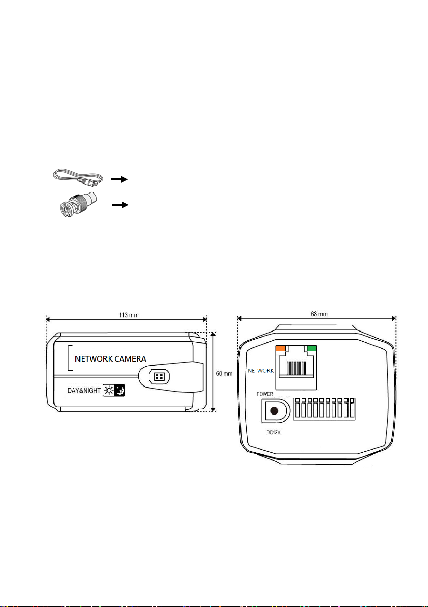
1-3 Packaging Contents
RCA Video cable x 1 ea
RCA to BNC
Please check the contents of your new Network IP Cam era when you unpack the packag e. If any
item is mi ssing, please contact your dealer o f purchase for help. The package includes the
following items:
Network IP Camera x 1ea
Bundle NVR & CMS software CD x 1ea
Quick User manual x 1ea
Access ory pack age x 1 set.
RCA Video Cable: It is connected to a portable displayer and used for adjust the focus of IP
camera. If you intend to use it for an ac tual monitori ng camera, use t he BNC cable instea d.
RCA to BNC converter: Convert the male RCA connector to m ale BNC connector.
Converter x 1 ea
1-4 Product Dimension
11
Page 12
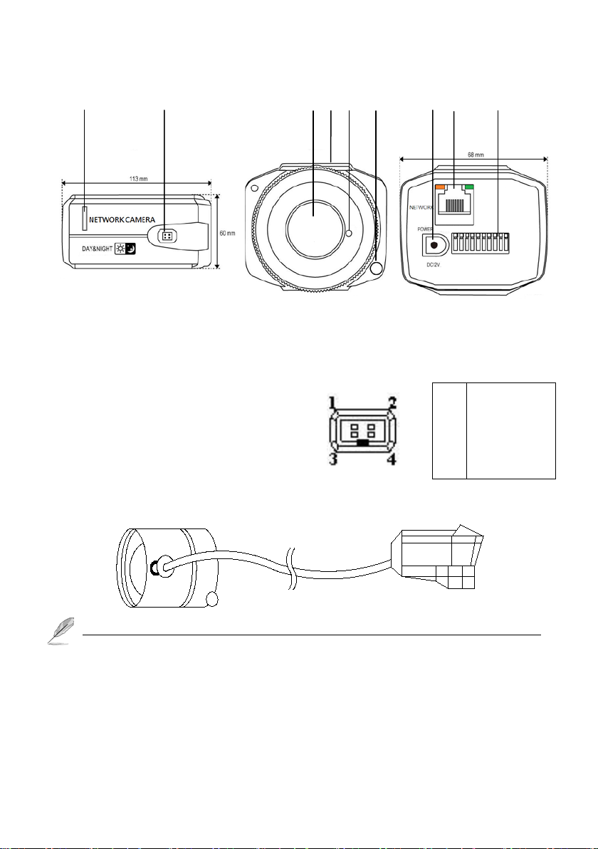
1-5 Product Parts Function Description
1 2 3 4 5 6 7 8 9
1. Micro SD Slot: Inserts SD card for video/snapshot recording. Max.32GB of SDHD card
supported.
2. Auto IRIS Connector: Connec ts to lens’s iris control cable.
Auto IRIS Socket: Connect to Auto IRI S L e ns
1
IRIS Control (+)
2
3
4
Auto Iris Lens Connector
Wipe out a dirty surface of the lens softly with a lens tissue to which you have applied ethanol.
3. Lens Adapter: Mounting C or CS-mount Le ns , there is a fix megapixels Lens come with the
camera.
4. Bracket mount hole: Connects to tripod or pan-tilt bracket; there’s another mounting hole located
at the opposite side of IP camera’s body hole.
IRIS Driver (-)
IRIS Control (-)
IRIS Driver (+)
12
Page 13

5. Camera Fix Screw: Used when the adjust focus of Lens already.
6. Light Sensor: Detect the light to enable /disable IR Cut; the setting mode must be “Active
“ mode.
7. Power Port: Used to plug the DC 12V power adapter when no use PoE Hub.
8. Network Port: Used to connect a PoE or LA N c a ble. Powe r indicator (Orange LED) will be on
when connect with the PoE Hub; the Orange LED will be fla sh when plug t he communicat ion is
available.
9. Terminal Bl ock : See the pin define as below:
Video Out: Video analog signal output port connected to the monitor.
Audio out: The terminal block is connected t he speak er to out put voice.
Audio in: The terminal block is connected the microphone for audio signal input.
Ground: Common port w here t he Video out /Audio in & Audio out si gnal is connec ted.
Alarm in: Digital input; Accept dry contact signal only.
Alarm out: Digital output; Connects to external peripherals by wire.
Sensor in: Used to connect the external light sensor to detect the light to enable /disable IR
Cut; the setting mode must be “Passive “ mode when used the external light sensor.
Ground: Common port w here t he alarm in and alarm out signal is connected.
Ground: Common port of DC12V.
DC12V out: Provide DC 12V power source the other device applicat ion s uc h a s m ic rophone .
13
Page 14

Chapter 2. Camera Installation
2-1 Mounting the Lens
Disconnect the power before proceeding.
Mounting the CS lens: T urn the optional CS lens clockwise to insert it.
Mounting the C lens: T ur n the C m ount adaptor clockwise to insert it and do the same with
the C lens.
Connecting the Auto Iris Lens connector: Insert the lens
connector into the corresponding hole of the camera.
Focusing: Turn the lens left or right to control the zoom and
focus the lens so that you can view a clear, sharp object.
2-2 Inserting/Removing an Micro SD Memory Card
Inserting Micro SD Memory Ca rd: Push the Micro SD memory car d in the directi on of the
arrow shown in the diagram.
Removing Micro SD Memory Card: Gently press down on the exposed end of the memory card
as shown in the diagram to eject the mem ory ca rd f r om the s l ot.
14
Page 15

2-3 Connecting to Audio Input / Output
Connect the audio in port of the camera with the mic rophone whic h provides 2Vp-p output level.
Connect the audio out port of the camera with the speaker which support amplify function.
Check the specifications for audio input a nd output.
Audio Codec: G.711,AAC 64kbps 8kHz sampling .
Audio in: Used for mono signal line input (Max.2.4 Vp-p)
Audio out: Used for mono signal line output ( 35mW) and impedance 600 Ohm.
2-4 Alarm I/O Wiring Diagram
Connecting to the I/O port box
Connect the Alarm I/O signal to the corresponding port of the rea r port box.
15
Page 16

Chapter 3. Running IP Camer a by Witness Pro NVR soft ware
3-1 Network Deployment
General Connection (without PoE)
1. Connect RJ45 Ethernet cable to a switch. Use a Category 5 Cross Cable w hen your network
camera is directly connected to PC.
2. Connect the power cable from the Network Camera to a power outle t.
3. If you have external devices such as sensors and alarms, make the connect ion from the general
I/O terminal block
Power over Ethern et (Po E)
The Network Camera is PoE-compliant, allowing transmission of power and data via a single
Ethernet cable. Follow the above i llustration to connect the Network Camera to a PoE-enabled
switch via Ethernet cable.
16
Page 17

3-2 Install Witness Pro NVR software
Fig. 1
You can use your new Network IP Camera by its web user inte rfac e v There is a NVR so ftwar e
CD comes with IP camera which allow you run 32/64 channels IP cameras on a PC. Please
follow the steps below to complete the installation of Witness Pro NVR software.
Step 1. While into W indows, and insert the I-View DVR software CD into a CD/DVD drive.
Step 2. Select the NVR64 or NVR32 software
.
Step 3. Select the installation language and
press the “OK” button to continue.
.
Fig. 1-3-1.2 Choose a se tup language
Step 4. Press the “Next” button to start the
installation process..
-3-1. 1 Installation M enu
Fig. 1-3-1.4 Installation Startup
17
Page 18

Fig. 1
Step 5. Click the “Browse” button to install
into a different directory, otherwise click
on the “Next” button to inst all the
software into the proposed director.
Fig. 1-3-1.5 Installation
Step 6. Select “No, I will restart my computer later”
and press on the “Finish” button to exit.
-3-1. 9 Restart the computer
18
Page 19

3-3 Setting IP camera for W itn ess Pro NVR software
Fig A
Fig B
Click “ Start “ >> “ All Programs” >> “Witness NVR32 Pro”, then select the “ Video
Parameters setup- ezSetup” accessory program to setup the parame ters. You will see the
diagram as below
Disable channel: This will disable the selected channel when enable this f unction.
Install video codec: Install the video codec, if you connect IP camera at firs t tim e.
Vendor & Model: Select the correct brand and model for the connected IP camera. You also
19
Page 20

can select “Onvif” if your IP camera support Onvif compliant and not on the list. ou can
check the used camera support Onvif compliant from: http://www.onvif.org
setup “ icon to setup the parameters which you want to run on the Hybri d DVR or NVR.
Compress: Select the suitable c ode c for video recording a nd transmission.
Recording resolution: Select the resolution for video recording and display .
Frame rate: Select the frame rate for video recording and display .
Rate Control: You can choice video quality or bit rate from this tab. Good video quality or
large bit rate request bigger storage capability .
IP address: Entry the correct IP address for the connected IP camera. If you do not know t he IP
camera’s IP address, you can click “Find” icon to find out the curre ntly connect ed IP cam eras
User name & Password: The user name and password must be matched the setting of IP
camera which you want t o connect.
.
The default User n ame / Passwo rd is “ admin / 123456 “ and IP address is 192.168.0.123.
Some special issues to cause cannot find out the IP address that you can try the
192.168.123.123
Find: Click this icon to find out all the currently connected IP cameras on the list. You will
find out the network information of each IP camera. Please r efer the diagram shown as above
Fig A. Click the IP address and “Select” icon, the IP camer a information will be show on.
System Firmware update: Click “System Firmware update icon” icon to update the
newest IP cam er a f irmware; you can check and download the newest firmware version from
our website: www.i-view.com.tw
Change IP: Click “Change IP” icon to setup the DHCP or Static IP address and also
modify the username /Password. Please refer to Fig B diagram. After modification, click
“Change” icon to confirm the setting.
Discover: Click “Discover” icon to research the IP address of system.
Reboot: Click “Reboot” icon to restart this IP camera.
Go Web: Click this icon to enable the I.E. Browser to check/setup the detail parameters.
Select: Choice the IP camera which you find out from the system and then click “Select”
icon to assign this IP camera into the camera c hannel of Witness NVR.
.
. Click “ Onvif
20
Page 21

Advance setup: Click this icon will enable the detail parameters setting of IP camera. Y ou need
to load the Active X if this NVR is activated this process at first time.
The differen ce IP camera br and has it s own “Find” and “Advance setup” setup diagram and
setting process. For the detail information, please refer to the IP cam era operation me nu.
HTTP po rt & RTSP port: The both port number must be matc hed the setting of IP cam era..
Display streaming: You can select the “Dual streaming” or “Same as recording” mode; If
you select the “Dual streaming” mode, the live display video will show lower resolution
(320*240) for split video and higher resolution (same as recording resolution; such as
1920*1080) for pop-up to single video on the screen. This Dual streaming mode for live
display can save a huge CPU loading w hen decoding the vide o streaming.
Capture audio: You can recor d sound by m icrophone f rom audio i nput por t of IP camera.
Synchronization with the DVR time: Check to synchronize the time of IP camera with DVR.
Condition (AWB): Choice the parameters to suit for the camera install location.
Reboot: Click this icon will reboot the IP camera. .
Setup: Click this icon for detail setting of IP camera; you may not need to I.E. Browser for th e
detail IP cam era setti ng. Please refer the diag ram as below (For I-View’s IP camera only):
The detail NVR software operation , please refer to the Witness P ro software operation file
which built in the CD.
21
Page 22

Chapter 4. Run the IP camera from I.E. Browser
You can use your new Network IP Camera by its web user interface via I.E. web browser.
The requirements for viewing IP camera are as below:
OS: Microsoft Windows 2000/XP/Vista/7/8.
Browser: IE6 or above.
Cell phone: 3GPP player.
Quick Time: 6.0 or above.
You must know the IP a ddress of IP Camera bef ore you ca n connect to it. The IP Camera will
use DHCP server on your local network to obtain a n IP addres s automatically by def ault. So,
you can check your DHCP server’ s I P address lease table to find the IP addr ess of IP Camera or
also can use the utility program ‘IPSerch.exe’ to find the IP a ddress of I P Camera , which is come
with the CD-ROM.
Please follow up the processes as below to find out the IP address of IP camera by I PSearch utility.
Step 1. Click “IPSearch.exe “program will show the window as below.
22
Page 23

Step 2. Press “Search “but ton to search f or all IP Cameras on your loca l network.
Step 3. If you need to change IP address or user acces s info rmation on th e sel ected IP Camera,
change the IP addre ss and Getway I P, then click the “Modify” button to save the setting.
Step 4. If you no longer need to use this utility , click “Exit” button to close it.
The defau lt User name / P assword is “ admin / 123456 “ and IP address is 192.168.0.123.
.
Some special issues to cause cannot find out the IP address that you can try the
192.168.123.123.
Make sure all IP Cam eras are powe red on and connec t to local netw ork first.
If you have several network connections, please disable connections that are not connected to
IP camera , otherwise the IPSerch.exe program may fail to search IP camera.
4-1 Install ActiveX Plug-in on I.E. Browser
You can c onnec t to the IP camer a by Internet Expl orer or other web browsers for remote viewing
by entering IP address in address bar. When you c onnec t t o IP Camera, the use login screen will
appear when you get c onnec ted. Please entry the user name / password to login.
The default User name / Password is “ admin / 123456 “ and IP a ddress is 192.168.0.123
If you connect to IP Camera for the first time, you’ll see the following message, this mes sag e
prompts you that you need to install A ctiveX plug-in before you can see the video from IP
Camera.
23
Page 24

IE 8 and earlier ver sion:
Right click the indication bar and click: “Install This Add-on for A ll Users on T his Computer…”
to install ActiveX plug-in.
IE 9 version:
Click ‘Install’ button located at the bottom of IE to install ActiveX plug-in. If you’re prompted
that the Windows Firewall has bl ocke d some features of this pr ogram’
Click “Allow access” button to enable the IP Cam era function pr operly.
When you’re installing Internet Explorer plug-in, you may als o be pr om pted the diagram. Please
click “Yes” to allow changes.
24
Page 25

4-2 The Function Description of Live Window
1 2 3 4 5 6 7 8 9 10
After ActiveX plug-in is installed, you should be able to see the live video from IP camera as
below window.
This section introduces the function buttons of live window. You can test the IP camera function
from your Brower. The button functi ons a re a s below:
1. Parameters setup: This menu, you configure basic IP camer a settings like data transfer p rotocol
and data storage folder…etc.
2. Focus/Brightness: This section allows you to setup the focus /brightness of PTZ camera.
3. Play button: This button enables the live video.
4. Snapshot button: Take a snapshot or camera video and save im age f il e on your computer.
5. Recording button: Recording the live vide o on your computer.
6. Stop button: This button disables the live video.
25
Page 26

7. Pan/Tilt/Zoom button: Move the Pan/Tilt/Zoom positi on of IP Speed dome camera.
8. Storage path : Click “ Setup” button to setup the storage path.
9. Video Stream: Select the video stream mode Main/Sub streaming on the live video.
10. Live vi deo: The main screen to sh ow the live video, cl ick “ Esc “ key to enlarge the video
screen, click again restore the screen size.
4-3 The Network setup Function Description
In ‘Network setup’ menu, you can configure basic IP camera settings like data transfer protocol
and data storage folder…etc.
Network status: Click this button to check the current Mac address, IP address, type,
Gateway..ect informa tio n of IP camera.
Ethernet setup: Click this but ton to modify t he current IP address, enable/disable DHCP a nd
DNS IP address.
26
Page 27

ADSL setup: Enable the ADSL ne tw ork when you use the 3G m odel adapter for the IP camera.
DDNS setup: You can setup the DDNS for this IP camera , our curre nt DDNS including
dyndns.org.
UPNP setup: Enable/Disable UPNP function for this IP camer a.
FTP account: Click this button to setup the FTP server for “A larm trigger”, “View log” , “ System
configuration” backup.
ADSL setup: Enable the ADSL network when you use the 3G model adapter for the IP camera.
27
Page 28

SMTP Account setup: You can setup the email notify via thi s sec tion.
Streaming setup: You can setup the port number, access protocol from this section.
Platform setup: Click t his button to set up the IP camera l ogin information.
28
Page 29

4-4 The Media setup Function Description
In ‘Media setup’ menu, you can configure video, audio codec, video parameter, video format
and …etc.
Video capture setup
IR Cut setting: You must e na ble “ Passive “ and no Kee p c ol or mode when you use I R ty pe
IP camera .
Video Capture setup: You can change the video parameters base on the using environment,
if it is needed.
Please choice the correct “ Video format” on your area, you ca n base on the frequency of
voltage of your country. If t he fr e que ncy does not match your setting that w i ll s how s cr oll
noise on your video.
Privacy Mask: Click this button to setup the Privacy mask, it can allow to setup 4 areas Privacy
mask on Sub and Main streaming.
29
Page 30

Time and Title: Click the button to enable t o paste the Time stamp/ Camera Title on the
video on difference position of IP camera.
Video Encode setup: You can c hange the resolution, bit rate a nd frame rate for the s ub a nd
main streaming of I P cam era .
The user can select “VBR”, “CBR”, and “CVBR” for the c om pression mode.
VBR (Variable Bit Rate): VBR files vary the amount of output data per time segme nt. It
allows a higher bitrate (and therefore more storage space) to be allocated to the more
complex segments of media files while less space is allocated to less complex segments.
CBR (Constant Bit Rate): The rate at which a codec's output data is constant. CBR woul d
not be the optimal choice for storage as it would not al locate enoug h data for complex
sections (resulting in degraded quality) whi le wasting data on s imple sections .
CVBR: It is the neutral compression mode between VBR and CBR.
I-Frame interval: It is the least compressible but doesn't require other video frames to
decode. Less num be r of I -Frame interval will get less size of video streaming, but the video
30
Page 31

quality will be worse when image change rate is high.
Picture Capture: Click this button to enable snapshot function, it allows to setup the video quality,
snapshot speed and snapshot from which video streaming.
Audio Capture: Click this button to se tup the a udio rec ording, it supports the gain from 1-100.
Audio Encode: Click this button to se tup the audio encode , there are 2 audio c odec (G7.11/AAC.)
PTZ setup: You can setup the PTZ protocol via RS-485 interface.
31
Page 32

4-5 The Record and Replay Function Description
In ‘Record and Repla y ’ menu, you can configure video recording, snapshot and storage me dia f rom
this section.
Storage Info: Click this button to check the status of on board storage devices.
Playback: Click this button to search the recorded video clips.
Record setup: Click this button to setup t he type of triggere d recording, storage media and
schedule recording. You can setup the Pre recording & Post recording period with the video and
picture format on difference storage device.
32
Page 33

4-6 The Alarm Setup Function Description
In ‘Alarm setup’ menu, you can configure Video motion alarm, Sensor alarm, Video loss alarm,
Storage full alarm.
Motion detection alarm setup: Click t his button to se tup the motion detec tion area, sensitivity,
schedule and trigger alarm output.
IO input alarm setup: Cl ick this but ton to setup the alarm input type ( High to Low or Low to
High), Schedule and trigger alarm output.
Video loss alarm setup: Click this button t o setup trigger al arm output when Video loss.
Storage full alarm setup: Click this button to setup trigger alarm output when storage device is
full.
33
Page 34

4-7 The System Setup Function Description
In ‘System setup’ m e nu, you can get the Firmware version, setup t he timer, setup password, Save
configure, restore configure, reboot IP camera, update Firmware and choice Language
System info: Click this button to check the Firmware/O.S./Webpage version and product series
number.
Account Manager: Click this button to create a new user or enable/disable available user. There
are three user accounts, V iewer, Operator and Administer.
Time setup: Click this button to setup the time of IP camera. There are 3 ways to adjust the
timer of IP camera.
Adjust the timer by Manual: Select the time zone of residence from dropdown me nu to keep
correct date and time.
Synchronize with local time: Select this item and IP camera will synchronize the Date/ Time
34
Page 35

with your computer’s (or NVR) time as i ts time .
Synchronize with NTP Server: Select this item and IP camera will keep its date / time s etting
synchronized with specified time server (NTP server). Please input NTP server’s IP address or
DNS in ‘NTP Server Address’ field, and select time update interval from ‘Update Interval’
dropdown menu.
If this IP camera can’t access Internet, you must have a time server on local area network, or
set the time manually .
Log setup: Click this button to setup the Log setup parameters; you can choice the log type,
keeping period and auto back to FTP server or send via Email.
System Log: Click this button to search the View log via type and time period.
Log file: Click this button to maintain the Log file. You can download or delete Log file from
this section.
35
Page 36

Configure Manage: Click this button to Upload /Downl oad the System configuration; you ca n
choice the backup the system configuration file to FTP server or send via Email .
Restore conf i gura t ion: Click this button to restore the factory default setting.
System update: Click this button to upgrade IP camera’s firmware. Click ‘Browse’ button to
select a firmware image file on your computer first, then click ‘Update’ button. The IP camera
will auto reboot after update the Firmware.
Reboot: Click this button to reboot the IP camera.
Language: Click this button to choice difference language version.
36
Page 37

Chapter 5. Troubleshooting
Before you send this IP Camera back to your dealer when you found this IP Camera is not working
properly, please checks the table as below to save your time .
Problem description Possible soluti o n (s)
Can’t connect to IP Cam era Check the IP a ddress a nd port number is c orrect or not
Make sure the entry User name/Password is correct.
Make sure t he port num ber is opene d f rom the NVR and Route r.
Make sure the network cable is correctly connected to your local
area network. (The green LED will be flash).
Make sure the IP camera and NVR at the same LAN segment.
Make sure the Switch Hub is workable .
Check the LAN cable and Ethernet port of NVR are workable.
Check IP camera is powered.
Check the IP address and port number setting is matched with IP
camera.
NVR had been installed the correct video codec.
No IP Camera found Make sure the network cable is correctly connected to your local
area network. (The green LED will be flash).
Make sure cam era powe r is on.
Make sure the Switch Hub is workable .
Check the LAN cable and Ethernet port of NVR are workable.
Check network routing cable(s).
Check cable distances do not exce ed operating distance.
No image If the place where I P camera is inst alled is to o dark, tr y to add
some lights when possible.
Chec k if t he re ’s anything cov e r ing t he l e ns .
NVR had been installed the correct video codec.
37
 Loading...