

Page 1
5
1
3 3
2
4
5
6
5
V1.0
9
3
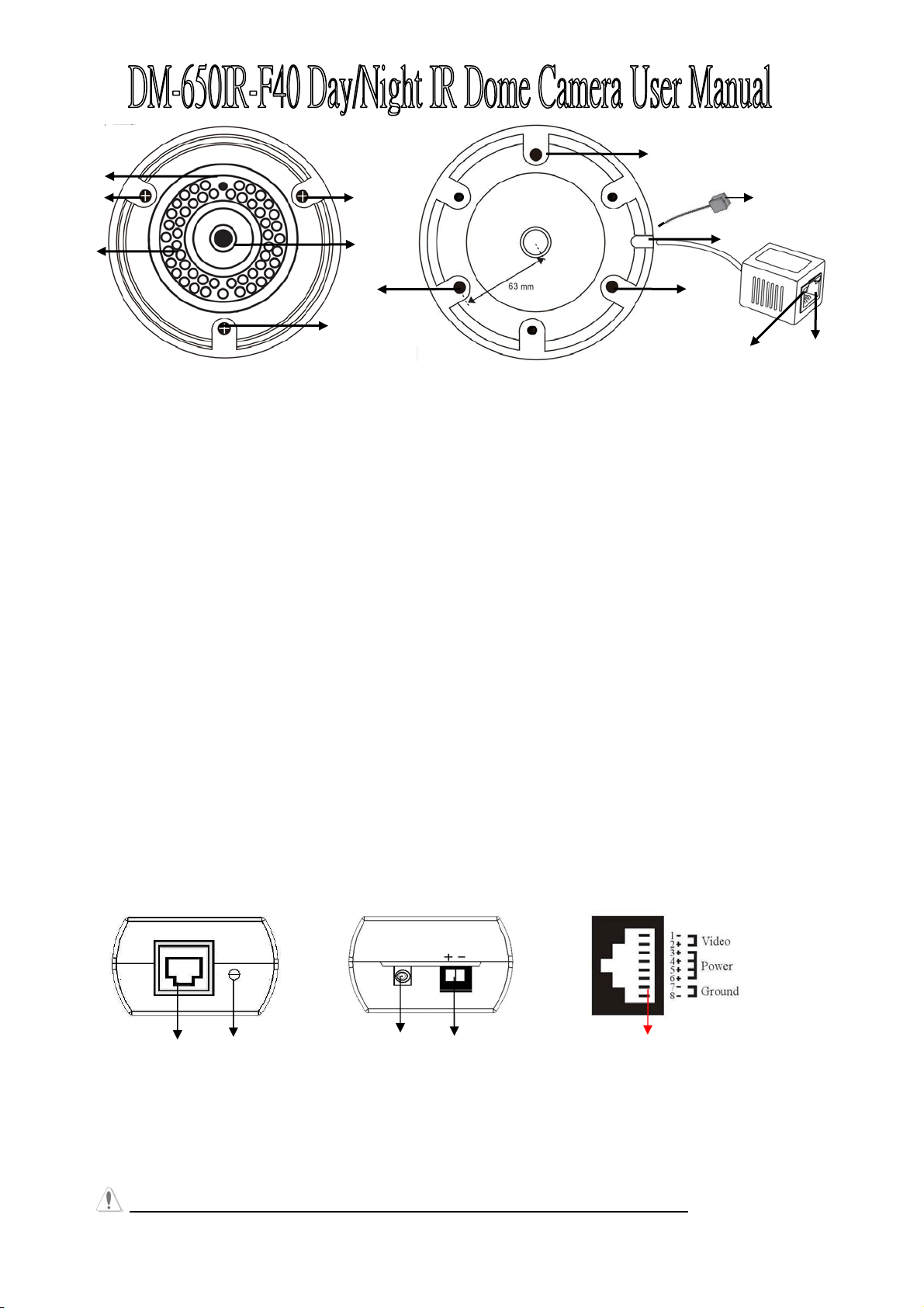
DM-650IR-F40 IR Dome Camera Function Description:
1.) Sensor: To detect the luminance of environment, the LED will be turned on when lower than 0.5 Lux.
2.) Lens: 4 mm IR Lens. Provide 6mm/8mm as alternative choice.
3.) Side Screw: Screw the camera housing; lose the screw to change the pan/tile view angle.
4.)
IR LED: Built in 36 pcsψ5 IR LED, the illuminate distance up to 25 meters.
5.) Mounting Hole: There are 3 holes to fix the camera housing on the ceiling.
7
8
6.) Gutter: To fix the wire cable of camera.
7.) Indicator: Power indicator, Green LED On: Power on. Green LED Off: No Power. Yellow LED: Reserve
8.) RJ-45 connector: To transmit Power and Video signals via UTP cable. Please refer to the RJ45 pin assignment.
OSD cable socket: To Connect OSD control cable for camera parameters setting. Please refer to OSD menu
9.)
Standard Accessories
¾ PRX-120VP Video/Power Balun for DVR site x 1 pc.
¾ Screws to fix camera housing x 4 pcs.
¾ L-Wrench screwdriver x 1 pc
¾ Menu x 1 pc
PRX-120VP Function Description: (On DVR site)
Front Panel
PRX-120VP Back Panel
RJ-45 Connector Pins Assignment
1 2
1.) RJ-45 connector: To transmit Power and Video signals via UTP cable. Please refer to the pin assignment.
2.) LED: Power indicator, LED On: Power on. LED Off: Not enough power or No Power.
3.) BNC Cable: For video output to DVR.
4.) Terminal Blocks: Power input for power transmission. Accept power range DC 24V or AC 24V-28V.
5.) RJ-45 pin Assignment: Connect the 4-pair UTP cable between DVR site and camera end for video/power transmission.
WARNING: This camera MUST use DC 24V power adapter for power transmission
3
4
1
5
.
Page 2

Installation Notes:
1. Please use point-to-point Unshielded Twisted Pair wire, 24-16 AWG, Category 2, 3, 4, 5, or 6.
2. Please measure the wire distance, Use only transceivers that are designed for that distance.
3. Please make sure the pair of wires carrying the video signal is sent as a twisted pair (e.g. the Blue-white/White-blue
wires twisted together as a pair), not a “split-pair” (e.g. blue-white conductor, part of one pair / orange-white conductor,
part of another pair).
Installation Warning:
1. Please DO NOT USE SHIELD TWISTED PAIR WIRE. This will cause severe degradation on distance performance and
reduce the inherent interference immunity.
2. Please DO NOT have “bridge-taps” or loading coils in installation.
3. If the phone company provides the cable runs between buildings, make sure it’s “dry copper”.
4. Due to near-end cross talk, don’t send a transmitted and a received signal in the same wire bundle. For safety, DO
NOT put UTP cable in the same conduit as high-voltage wiring.
Specification:
DM-650IR-F40 (60/80)
Image Device OSD Menu Setting
Image Device: 1/3“ SONY EXview HAD CCD II
(Effio-E)
Effective Picture Elements: PAL: 1024(H)x596
(V); NTSC: 1028(H)x508(V)
Video
Horizontal Resolution: Color: 650TVL, B/W:
700TVL
Video System: NTSC/PAL (Optional)
Video Output: 1Vp-p output with RJ-45 connector;
BNC type connector (Option)
Video Characteristic
Gamma Characteristic: 0.45
Sync. System: Internal
S/N Ratio: More than 50dB (AGC Off)
Shutter Speed Control: AUTO (1/50(60) ~
1/100,000 sec.)
Wide Dynamic Range: ATR Digital WD (ATR:
Adaptive Tone-curve Reproduction)
Lens & IR Illuminators
Lens: 4 mm / F1.6 (optional: 6mm/8mm)
Infrared Luminary: 36 pieces Ø5 IR-LED; up
to 25m illuminate distance for day & night
application
Dimension/Weight Minimum Illumination: Color: 0.03Lux@F1.0,
ψ135.5mm x 86 mm (H) / 0.45Kg
Operation Transmission Distance
Flicker Less: ON/OFF
Gain Control: Auto (4 steps)
Dynamic Noise Reduction: 2D
Motion Detection: ON / OFF (24x16 Zones)
Day/Night Mode: Color / B&W / AUTO / Ext.
Back Light Compensation: HLC / BLC / OFF
Privacy Mask: ON / OFF (8 programmable mosaic
zones)
Control Parameters: Menu OSD (With an optional
OSD cable control)
White Balance: ATW / PUSH / USER define /
ANTI CR / MANUAL / PUSH LOCK
Surge Protector
Video: Peak Inverse Blocking Voltage:
VPIB= 100V; Peak Pulse Current: Ipp=44A;
Clamping Voltage: 10V @ Ipp= 5A
Power: Max. Energy: 3.6J @10/1000µs;
Clamping Voltage: 16.8KA(1 Time)
/8.4KA(2 Time) @8/20µs (1 Time);
Insulation Resistance:≧10000MΩ
Illumination
B/W: 0 Lux (IR LED on)
Power Consumption: IR ON: DC 24V/140mA
max, IR OFF: DC 24V/25mA.
Operation: Temperature -10°C ~ 50°C; Humidity
20% ~ 80% RH
Transmit Video / Power up to 300 meters via Cat. 5
or better UTP cable
Housing
Waterproof IP67 metal housing 3-Axis bracket.
2
Page 3

Standard Accessories
↲
r
¾ PRX-120VP Video/Power Balun for DVR site x 1 pc.
¾ Screws to fix camera housing x 3 pcs.
¾ Bracket sticker label x 1 pc
¾ Menu x 1 pc
¾ L-Wrench screwdriver x 1 pc
¾ OSD controller cable x 1 pc (Optional)
Setup the camera parameters by OSD menu
Press button to
enable OSD or Ente
Plug OSD cable (Option) on the socket cable and there is a button on OSD cable for further configures camera parameters.
Enter the camera configuration OSD menu Press button
If you want to ……
Move to the sub-menu you want
Change setting
Press
Push button to↑ / ↓direction
Push button to ← / → direction
Enter the configuration page of an option Press button
For options with↲ , press the button“↲ ”(Enter)to enter their respective setting pages.
SETUP MENU OPTIONS
LENS AUTO↲ TYPE DC/VIDEO
MODE OPEN/AUTO/CLOSE
SPEED 0~255
MANUAL
SHUTTER/AGC AUTO↲ HIGH LUMINANCE MODE SHUT+AUTO IRIS
/ AUTO IRIS
BRIGHTNESS 0~255
LOW LUMINANCE MODE AGC/OFF
BRIGHTNESS ×0.25 / ×0.50 / 0.75 / ×1.00
MANUAL↲ MODE SHUT+AGC
SHUTTER 1/50
AGC 6.00/12.00/18.00/24.00/30.00/36.00/42.00/44.80
WHITE BAL ATW↲ SPEED 0~255
DELAY CNT 0~255
ATW FRAME ×0.50 / ×1.00 / ×1.50 / ×2.00
ENVIRONMENT INDOOR / OUTDOOR
PUSH
USER1↲ /
USER2
ANTI CR
MANUAL↲ LEVEL 015~056
PUSH LOCK
BACKLIGHT OFF/BLC/HLC
PICT ADJUST
ATR O FF
DAY/NIGHT AUTO↲ BURST ON/OFF
MIRROR OFF/ON
ON↲ LUMINANCE LOW / MID / HIGH
COLOR
B-GAIN / R-GAIN 0~255
↲
BRIGHTNESS / CONTRAST
/SHARPNESS /HUE / GAIN
CONTRAST LOW / MIDLOW / MID / MIDHIGH / HIGH
DELAY CNT /
DAY→NIGHT/NIGHT→DAY
0~255
0~255
3
Page 4
B / W
↲
↲
EXT1 & EXT2 for external trigger signal. (Enable EXT1 for IR LED optimizer function )
PRIVACY OFF
ON AREA SEL 1/4、2/4、3/4、4/4
MOTION DET OFF
ON↲ DETECT SENSE 0~127
NR
CAMERAID OFF/ON↲
SYNC INT
LANGUAGE ENGLISH /日本語 / DEUTSCH / FRANCAIS / PYCCKNŇ / PORTUGUÊS / ESPAŇ OL
CAMERA RESET
BURST ON/OFF
IR OPTIMIZER ON/OFF
MODE AUTO/CENTER
LEVEL 0~31
TOP/BOTTOM 0~244
LEFT/RIGHT 0~378
COLOR 0~8
TRANSP 0.00/ 0.50/ 0.75 /1.00
MOSAIC ON / OFF
BLOCK DISP OFF /ON / ENABLE↲
MONITOR AREA ON/OFF
AREA SEL 1/4、2/4、3/4、4/4
TOP / BOTTOM 0~288
LEFT / RIGHT 0~468
NR MODE Y/C ; Y ; C ; OFF
Sub-menu Brief Description
SUB-MENU DESCRIPTION
LENS Select and set the type of your lens: DC Driver, Video Driver or board lens.
SHUTTER / AGC Select “AUTO” to allow the camera to act automatically when the light condition of the
environment changes. Select “MANUAL” to fix the shutter and AGC modes of the camera
no matter how the light condition of the environment changes.
WHITE BAL Process the current image to retain color balance over a color temperature range.
BACKLIGHT Adjust the image to compensate for an area that is overpowered by brightness because of
excessive light.
“BLC” is to automatically adjust the level of the light to show more details in the dark
environment. And the “HLC” is to mask extremely bright areas.
PICT ADJUST Adjust the color of the pictures in, for example, brightness, contrast, sharpness and hue.
ATR D-WDR to increase the image recognized capability of the overexposed and dark areas.
PRIVACY Mask areas that should be not visible.
DAY / NIGHT Set the night surveillance mode to color or B/W.
NR Reduce noise by separating luminance (Y) and chrominance (C) settings.
CAMERA ID Set the title of the camera.
LANGUAGE Select the language of the menu on-screen display.
CAMERA RESET
↲ to restore all settings to their factory default values.
Press
Phone: 886-3-510-3001 Fax: 886-3-510-3002
Email: support@i-view.com.tw
Website: www.i-view.com.tw
4
 Loading...